KR101203497B1 - Modular wearable circuit - Google Patents
Modular wearable circuitDownload PDFInfo
- Publication number
- KR101203497B1 KR101203497B1KR1020077009593AKR20077009593AKR101203497B1KR 101203497 B1KR101203497 B1KR 101203497B1KR 1020077009593 AKR1020077009593 AKR 1020077009593AKR 20077009593 AKR20077009593 AKR 20077009593AKR 101203497 B1KR101203497 B1KR 101203497B1
- Authority
- KR
- South Korea
- Prior art keywords
- garments
- conductive
- connection points
- electronic
- garment
- Prior art date
- Legal status (The legal status is an assumption and is not a legal conclusion. Google has not performed a legal analysis and makes no representation as to the accuracy of the status listed.)
- Expired - Fee Related
Links
Images


Classifications
- A—HUMAN NECESSITIES
- A41—WEARING APPAREL
- A41D—OUTERWEAR; PROTECTIVE GARMENTS; ACCESSORIES
- A41D13/00—Professional, industrial or sporting protective garments, e.g. surgeons' gowns or garments protecting against blows or punches
- G—PHYSICS
- G09—EDUCATION; CRYPTOGRAPHY; DISPLAY; ADVERTISING; SEALS
- G09B—EDUCATIONAL OR DEMONSTRATION APPLIANCES; APPLIANCES FOR TEACHING, OR COMMUNICATING WITH, THE BLIND, DEAF OR MUTE; MODELS; PLANETARIA; GLOBES; MAPS; DIAGRAMS
- G09B23/00—Models for scientific, medical, or mathematical purposes, e.g. full-sized devices for demonstration purposes
- G09B23/06—Models for scientific, medical, or mathematical purposes, e.g. full-sized devices for demonstration purposes for physics
- G09B23/18—Models for scientific, medical, or mathematical purposes, e.g. full-sized devices for demonstration purposes for physics for electricity or magnetism
- G09B23/183—Models for scientific, medical, or mathematical purposes, e.g. full-sized devices for demonstration purposes for physics for electricity or magnetism for circuits
- G—PHYSICS
- G09—EDUCATION; CRYPTOGRAPHY; DISPLAY; ADVERTISING; SEALS
- G09B—EDUCATIONAL OR DEMONSTRATION APPLIANCES; APPLIANCES FOR TEACHING, OR COMMUNICATING WITH, THE BLIND, DEAF OR MUTE; MODELS; PLANETARIA; GLOBES; MAPS; DIAGRAMS
- G09B23/00—Models for scientific, medical, or mathematical purposes, e.g. full-sized devices for demonstration purposes
- G09B23/06—Models for scientific, medical, or mathematical purposes, e.g. full-sized devices for demonstration purposes for physics
- G09B23/18—Models for scientific, medical, or mathematical purposes, e.g. full-sized devices for demonstration purposes for physics for electricity or magnetism
- G09B23/182—Models for scientific, medical, or mathematical purposes, e.g. full-sized devices for demonstration purposes for physics for electricity or magnetism for components
Landscapes
- Engineering & Computer Science (AREA)
- General Physics & Mathematics (AREA)
- Physics & Mathematics (AREA)
- Educational Administration (AREA)
- Theoretical Computer Science (AREA)
- Mathematical Optimization (AREA)
- Mathematical Physics (AREA)
- Pure & Applied Mathematics (AREA)
- Business, Economics & Management (AREA)
- Computational Mathematics (AREA)
- Algebra (AREA)
- Educational Technology (AREA)
- Mathematical Analysis (AREA)
- Health & Medical Sciences (AREA)
- General Health & Medical Sciences (AREA)
- Physical Education & Sports Medicine (AREA)
- Textile Engineering (AREA)
- Professional, Industrial, Or Sporting Protective Garments (AREA)
- Outerwear In General, And Traditional Japanese Garments (AREA)
- Outer Garments And Coats (AREA)
- Gloves (AREA)
Abstract
Translated fromKoreanDescription
Translated fromKorean본 발명은 일반적으로 스마트 의복(smart garment)들에 관한 것이다. 보다 세부적으로는, 본 발명은 상이한 전자 작동을 달성하기 위하여 다양한 모듈식 상호연결형 컴포넌트(modular interconnecting component)들로 전기 회로를 조립하기에 적합한 스마트 의복 시스템에 관한 것이다.The present invention relates generally to smart garments. More specifically, the present invention relates to a smart garment system suitable for assembling electrical circuits into various modular interconnecting components to achieve different electronic operations.
전자 회로들의 구조분야의 학생들과 그 밖의 사람들을 교육시키고 즐겁게 하기 위해 여러 교육용 장치들 및/또는 게임들을 사용하는 것과 그와 관련된 다양한 전기적 및 전자적 컴포넌트들의 사용은 공지되어 있다. 교육 연구원들은 사람들, 특히 아이들을 가르치는 하나의 효율적인 방법은 그들을 가능한 한 학습 과정에 열중시키는 것임을 알게 되었다. 따라서, 수년간 상이한 수 많은 학생-참여형 교육용 키트(kit)들이 개발되어 왔다. 이해하기 어려울 수 있는 추상적 관념을 가르치기 위한 교육용 키트들의 예시들인 미국 특허 제 3,656,242; 4,376,538; 및 5,742,486을 참조한다. 단순화한 컴포넌트들을 구비한 이러한 키트들은 기초 전자기기와 회로 설계를 가르치기에 특히 유용하도록 여러 기본적인 전기 또는 전자 회로들을 형성하기 위한 수단을 제공한다. 그러나, 이러한 수 많은 공지된 교육용 키트들이 비교적 간단함에도 불구하고, 이들은 더 어린 아이들을 가르치는 용도와, 또한 학교 설비에서 종종 발견되는, 많은 그룹이 학습하는 환경에서의 용도에도 여전히 부적절하다. 따라서, 전자기기 및 전자 컴포넌트들과 관계된 기본 원칙들 및/또는 관념들을 가르치고 표현하는, 직관적이며 매력적인 방법에 사용될 수 있는 교육용 도구를 제공할 필요가 있다.The use of various educational devices and / or games to educate and entertain students and others in the field of electronic circuits is known and the use of various electrical and electronic components associated therewith. Education researchers have found that one efficient way to teach people, especially children, is to engage them in the learning process as much as possible. Thus, many different student-participatory kits have been developed over the years. US Patent No. 3,656,242, which is an example of educational kits for teaching abstract notions that may be difficult to understand; 4,376,538; And 5,742,486. Such kits with simplified components provide a means for forming several basic electrical or electronic circuits that are particularly useful for teaching basic electronics and circuit design. However, although many of these known educational kits are relatively simple, they are still inadequate for teaching younger children and also in environments where many groups learn, often found in school facilities. Accordingly, there is a need to provide educational tools that can be used in an intuitive and attractive way to teach and express basic principles and / or concepts related to electronic devices and electronic components.
본 발명은 전기적 또는 전자적 기능들을 수행할 수 있는 상이한 여러 회로들을 한정하는 세트(set)로서 연동할 수 있는 임의 수량의 의복들을 제공함으로써 기본 원칙들 및/또는 전자기기와 전자 컴포넌트들의 개념들을 가르치고 표현하는데 사용되는 교육용 도구들과 관계된 결점들 및/또는 단점들을 다루고 있다.The present invention teaches and expresses basic principles and / or concepts of electronics and electronic components by providing any number of garments that can work together as a set that defines several different circuits capable of performing electrical or electronic functions. It addresses the shortcomings and / or shortcomings associated with the educational tools used to do this.
본 발명의 도시적인 양상에서, 각각의 의복과 작동 가능하게 연계된 하나 이상의 전자 컴포넌트들과 하나 이상의 도전성 연결 포인트(point)들에 연결하기 위해서, 의복은 이 의복에 작동 가능하게 일체화되는 도전성 네트워크(network)를 갖는 스마트 의복이다. 본 발명의 유익한 특징은 상기 의복이 하나 이상의 전자 회로들을 한정하는 하나 이상의 상보적 의복들과 연동되도록 이와 연계되는 하나 이상의 전자 컴포넌트들로 작동하고 표시하는 점에서 확인된다.In an illustrative aspect of the present invention, in order to connect to one or more conductive connection points and one or more electronic components operatively associated with each garment, the garment is a conductive network operatively integrated with the garment. smart garment with network). Advantageous features of the present invention are identified in that the garment operates and displays one or more electronic components associated therewith to cooperate with one or more complementary garments defining one or more electronic circuits.
본 발명의 다른 도시적인 양상은 각각의 의복이 적어도 하나의 전자 컴포넌트로서 작동하고 표시하도록 그와 연계된 일체형 전자 기능들을 갖는 연동 의복들의 세트에 의해 한정되는 착용가능한 모듈식 회로를 포함한다. 상기 다양한 의복들은 전자 작동의 분류를 수행할 수 있는 임의의 상이한 여러 회로들을 한정하기 위해 연동식으로 연결하는 것이 유리하다.Another illustrative aspect of the present invention includes a wearable modular circuit defined by a set of interlocking garments having integral electronic functions associated therewith such that each garment operates and displays as at least one electronic component. It is advantageous for the various garments to be interlocked in order to define any different various circuits capable of performing the classification of electronic operation.
본 발명의 다른 도시적인 양상은 (ⅰ) 각각의 의복이 적어도 하나의 전자 컴포넌트로서 작동하고 표시할 수 있도록 의복들에 연계된 일체형 전자 기능들을 갖는 연동 의복들(10)의 세트를 공급하는 단계;Another illustrative aspect of the present invention comprises the steps of: (i) supplying a set of interlocking
(ⅱ) 작동 회로를 한정하는 전자 컴포넌트들을 배열하기 위해 상이한 의복들을 도전성으로 연결하는 단계를 포함하는 전기 회로 형성 방법에 관한 것이다.(Ii) conductively connecting different garments to align electronic components defining an actuating circuit.
본 발명의 추가적인 및/또는 대안적인 양상들, 특징들 및 장점들은 본 발명의 다양한 예시적인 실시예들에 대한 하기의 상세한 설명과 관련하여 명백해질 것이다.Additional and / or alternative aspects, features and advantages of the present invention will become apparent with reference to the following detailed description of various exemplary embodiments of the present invention.
본 발명의 보다 나은 이해를 위해서, 첨부 도면들과 함께 고려된 하기의 상세 설명에 언급된다.For a better understanding of the invention, reference is made to the following detailed description considered in conjunction with the accompanying drawings.
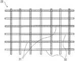
도 1은 본 발명의 예시적인 실시예에 따른 다양한 의복들의 개략도.1 is a schematic representation of various garments in accordance with an exemplary embodiment of the present invention.
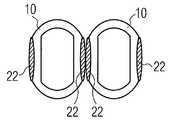
도 2는 본 발명의 양상에 따른 섬유 구조의 평면도.2 is a plan view of a fiber structure according to an aspect of the present invention.
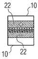
도 3은 도전성 연결을 제공하도록 작동 가능한 상호 연결에 적합하며 각 의복들과 작동 가능하게 연계된 개별 커넥터들의 개략도.3 is a schematic diagram of individual connectors operatively associated with respective garments, suitable for interconnection operable to provide a conductive connection;
도 4는 본 발명의 예시적인 양상에 따른 정합 맞물림으로 도시된 도 3의 커넥터의 개략도.4 is a schematic view of the connector of FIG. 3 shown in a mating engagement in accordance with an exemplary aspect of the present invention.
도 5a는 본 발명의 다른 예시적인 양상에 따른 정합 맞물림으로 도시된 도 3의 커넥터의 개략도.5A is a schematic view of the connector of FIG. 3 shown in a mating engagement in accordance with another exemplary aspect of the present invention.
도 5b는 도 5a의 정합 맞물림의 확대도.5B is an enlarged view of the mating engagement of FIG. 5A.
도 6은 본 발명의 다른 예시적인 실시예에 따른 한 세트 의복의 개략도.6 is a schematic representation of a set of garments in accordance with another exemplary embodiment of the present invention.
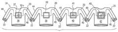
도 7은 시스템이 폐쇄 회로를 한정하는, 도 6의 세트에 관한 개략도.FIG. 7 is a schematic diagram of the set of FIG. 6 in which the system defines a closed circuit; FIG.
도 8은 시스템이 개방 회로를 한정하는, 도 6의 세트에 관한 개략도.8 is a schematic representation of the set of FIG. 6 in which the system defines an open circuit;
도면들을 참조하여, 특히 도 1에는, 일반적으로 도면 부호 10으로 표현된 본 발명에 따른 도식적인 예시에 의한 다양한 의복들이 도시된다. 도시된 바와 같이, 의복(10)은 예를 들어, 셔츠(12), 바지(14), 장갑(16) 및/또는 모자(18)를 포함하는 임의의 다양한 형태들을 가질 수 있다. 추가적인 또는 대안적인 의복들이 동일하게 사용될 수 있다. 각각의 의복(10)은 2개 이상의 도전성(conductive) 연결 포인트들(22 ; point)을 연결하는 도전성 네트워크(20 ; network)를 구비한다. 이 도전성 네트워크(20)는 이러한 의복이 컴포넌트(24)로서 표시하고 작동되도록, 의복에 내장되거나 일체형이 바람직한 적어도 하나의 전자 컴포넌트(24)를 포함한다.With reference to the drawings, in particular in FIG. 1, various garments are shown by means of a schematic illustration according to the invention, represented generally by the
도전성 네트워크(20)는 다양한 방법으로 만들어질 수 있다. 예를 들어, 도전성 네트워크(20), 또는 적어도 그 부분은 바람직하게는 의복 재료의 표면(26)과 일체형으로 연계된 인쇄된 도전성 잉크(ink)일 수 있다. 달리 또는 추가하여, 도전성 네트워크(20), 또는 적어도 그 부분은, 도 2에 도시된 바와 같이, 섬유 구조(28 ; fiber construction)을 통해 동일하게 만들어질 수 있으며, 이 섬유 구조(28)는 의복(10)을 형성하기 위해 사용되는 재료와 일체되는 가요성, 탄성 및 불연속(discrete) 도전성 네트워크(20)를 형성하는 제직(weaving), 재봉(sewing), 편직(knitting)으로 공지된 임의의 방법에 따른 하나 이상의 비-도전성 섬유들(31)과 엉킨 하나 이상의 도전성 섬유들(30)을 포함한다.The
연결 포인트들(22)은 본 발명으로부터 당업자에게 용이하게 명백해 질 여러 상이한 형상을 취할 수 있다. 예컨대, 본 명세의 일 양상에서, 각각의 연결 포인트(22)는 도 3에 도시된 바와 같은 도전성 섬유 영역(23 ; area)의 형상일 수 있다. 각각의 연결 포인트(22)는 예를 들어, 상술된 도전성 네트워크(20)와 유사한 섬유 구조로 만들어질 수 있다. 다시 도 2를 참조하여, 즉 도전성 비-도전성 섬유(30, 31)의 메시(mesh)가 가요성 직물 연결 포인트(22)를 만들기 위해 서로 얽히게 될 수 있다. 각각의 연결 포인트(22)는 또한 상이한 연결 타입들을 용이하게 하는 다수의 상이한 패턴들내에 형성될 수 있다. 예컨대, 도 4에 도시된 바와 같이, 각각의 연결 포인트(22)는 상이한 연결 포인트들(22) 사이에서 쉽고, 빠르며 분리가능한 도전성 연결들을 위해 의복(10)에 작동 가능하게 연계된 하나 이상의 자성체들(32 ; magnet)과 연동할 수 있다. 도 5a 및 도 5b는 다른 예시적인 연결 타입을 도시한다. 도시된 바와 같이, 각각의 연결 포인트(22)는 상이한 연결 포인트들(22) 사이의 쉽고, 빠르며 분리가능한 도전성 연결들에 적합한 도전성 후크(hook) 및 루프(loop)(즉, VelcroTM) 섬유 구조와 유사할 수 있다. 각각의 연결 포인트(22)는 복수의 상보적 의복(10) 중 임의의 것과 연계되는 복수의 상보적 연결 포인트들(22) 중 임의의 것과 도전성으로 연동하기에 적절한 것이 바람직하다.The
도 1을 재참조하여, 본원의 지침에 기초한 당업자에게는 용이하게 명백해지는 것처럼, 도전성 네트워크(20)와 다양한 연결 포인트들(22) 모두와 도전성으로 연계되도록 의복(10)에 내장되거나 일체형이 바람직한 임의의 하나 이상의 전자 컴포넌트들(24)은 다르게는 의복(10), 도전성 네트워크(20) 및 연결 포인트들(22)과 해제가능하게 연계될 수 있다. 예를 들어, 도전성 네트워크(20)를 따라 그에 도전성으로 연결되기 위해 상이한 위치들에서 해제가능하게 연결되는 것으로 도시된 컴포넌트들(24r)을 고려한다. 각각의 컴포넌트들(24r)과 의복(10) 사이의 해제가능한 도전성 연결을 용이하도록 하기에 적합할 수 있는 예시적인 연결 타입은 연결 포인트들(22)에 관해 상술된 것과 유사한 도전성 직물 상호연결 배치이다. 다양한 임의의 다른 도전성 연결 타입들이 동일하게 사용될 수 있다.Referring again to FIG. 1, any embedded or integral part of the
이제 도 6 내지 도 8을 참조하면, 본 발명의 양호한 양상에서, 임의의 의복들의 수량은 전기 또는 전자 기능들을 수행할 수 있는 여러 상이한 회로들을 한정하는 세트(set)로서 연동할 수 있다. 이러한 점에서, 의복들의 세트는 전자 회로들 및/또는 전자 컴포넌트들의 기본 원칙들을 표시하는 훈련 또는 교육용 도구/게임 용도에 적합하다. 예를 들어, 배터리(battery) 컴포넌트(37)를 한정하는 제 1 셔츠(36), 제 1 연결형 컴포넌트(39)를 한정하는 제 2 셔츠(38), 제 2 연결형 컴포넌트(41)를 한정하는 제 3 셔츠(40), 및 광(light) 컴포넌트(43)를 한정하는 제 4 셔츠(42)인 4개의 셔츠들을 포함하는 도 6에 도시된 셔츠 세트(34)를 고려한다.Referring now to FIGS. 6-8, in a preferred aspect of the present invention, the quantity of any garments can work together as a set defining several different circuits capable of performing electrical or electronic functions. In this regard, the set of garments is suitable for training or educational tool / game use that indicates the basic principles of electronic circuits and / or electronic components. For example, a
셔츠들(36, 38, 40, 42) 각각은 상술된 바와 같이 일체형 도전성 섬유 트랙(track) 또는 도전성 네트워크(20) 및 연결 포인트들(22)을 포함한다. 도시된 바와 같이, 연결 네트워크(20)는, 또한 각각의 소매와 연계되는 연결 포인트들(22)을 갖는 각 셔츠(36, 38, 40, 42) 각각의 소매들(44, 45)로 연장한다. 또한, 각각의 소매(44, 45)는 인접 셔츠의 상보적인 연결 포인트들(22)과의 적절한 상호연결을 용이하게 하기 위해서 표시(예컨대, "+" 또는 "-")될 수 있다.Each of the
도시된 바와 같이, 제 1 셔츠(36)는 배터리 컴포넌트(37)(예를 들어, 실질적으로 편평한 재충전 배터리)로서 작동하며 표시한다. 이 배터리 컴포넌트는 원격 전원(미도시)에 의해서 재충전될 수 있는 재충전용 배터리가 바람직하다. 이 배터리 컴포넌트(37)는 상당한 공간을 차지하지 않도록 비교적 편평한 저 프로파일(low profile)을 갖는 것이 바람직하다. 배터리 컴포넌트(37)는 상보적인 셔츠들(38, 40, 및 42) 중 임의의 하나 이상에 전력 공급하기에 적절한 것이 바람직하다. 본 발명의 양상에서, 배터리 컴포넌트(37)는 제 1 셔츠(36)의 표면에 분리되어 연결될 수 있다.As shown, the
제 2 셔츠(38)는 예를 들어, 제 1 연결형 컴포넌트(39)처럼 작동하며 표시한다. 제 1 연결형 컴포넌트(39)는 임의의 여러 전자 연결 소자(예를 들어, 와이어, 스위치, 분배기(divider) 등)일 수 있다. 배터리 컴포넌트(37)와 같이, 제 1 연결형 컴포넌트(39)는 셔츠(38)로부터 상당하게 돌출되지 않도록 저 프로파일이 바람직하다. 제 1 연결형 컴포넌트(39)는 임의의 2이상의 상보적 셔츠들(36, 40, 42)을 도전성으로 연결하기에 적합한 것이 바람직하다. 유사하게, 본 발명의 양상에서, 제 1 연결형 컴포넌트(39)는 제 2 셔츠(38)의 표면에 분리 연결될 수 있다.The
제 3 셔츠(40)는 예를 들어 제 2 연결형 컴포넌트(41)처럼 작동하고 표시한다. 제 1 연결 소자와 달리, 제 2 연결형 컴포넌트(41)는 통과하는 도전성 플로우(flow)를 조정하기 위해 그와 연계된 플로우 제어 수단(예컨대, 저항기, 축전기 등)를 구비할 수 있다. 제 1 연결형 컴포넌트(39)와 같이, 제 2 연결형 컴포넌트(41)는 임의의 2이상의 상보적 셔츠들(36, 38, 42)을 도전성으로 연결하기에 적합한 것이 바람직하다. 게다가, 본 발명의 양상에서, 각각의 상술된 컴포넌트들(37, 39)과 함께, 제 2 연결형 컴포넌트(41)는 제 3 셔츠(40)의 표면에 분리 연결될 수 있다.The
제 4 셔츠(42)는 예를 들어 광 컴포넌트(43)처럼 작동하고 표시된다. 광 컴포넌트(43)는 임의의 광원(예컨대, LED, 발광(luminescent), 백열광(incandescent), 형광(fluorescent) 등)일 수 있다. 광 컴포넌트(43)는 상술된 각각의 컴포넌트들(37, 39, 41)과 함께, 셔츠(42)로부터 상당하게 돌출하지 않도록 저 프로파일이 바람직하다. 유사하게는, 본 발명의 양상에서, 제 1 연결형 컴포넌트(39)는 제 2 셔츠(38)의 표면에 분리 연결될 수 있다. 제 1 및/또는 제 2 연결형 컴포넌트(39, 41)를 경유하여 배터리 컴포넌트(37)에 도전성으로 연결될 때, 밝아진다.The
본 발명으로부터 당업자에게 용이하게 명백해지는 것처럼, 하나 이상의 전자 컴포넌트들을 작동하고 표시하는 임의의 여러 추가적인 및/또는 대안적인 셔츠 또는 다른 의복 타입들은 본 발명에 따라 동일하게 사용될 수 있으며, 따라서 이는 본 발명의 범주에 해당한다.As will be readily apparent to those skilled in the art from the present invention, any of a variety of additional and / or alternative shirts or other garment types for operating and displaying one or more electronic components may be used identically according to the present invention, and thus It is a category.
이제 도 7과 도 8을 참조하여, 본 발명의 도시적인 양상에서, 셔츠들(36, 38, 40, 42)은 예를 들면, 도 7에 표현된 것과 같은 작동 회로(44)를 한정하도록 서로에 대해 위치될 수 있는 4명의 아이들에 의해서 착용될 수 있다. 도시된 바와 같이, 제 1 셔츠(36) 또는 배터리 컴포넌트(37)가 각각의 셔츠들에 연계된 연결 포인트들(22)을 경유하여 제 2 및 제 3 셔츠들(38, 40) 또는 연결형 컴포넌트들(39, 41)에 직접 연결되도록, 회로(44)는 원형으로 아이들을 위치시켜 생성될 수 있다. 따라서, 제 4 셔츠(42) 또는 광 컴포넌트(43)는 제 2 및 제 3 셔츠들(38, 40)을 경유하여 제 1 셔츠(36) 또는 배터리 컴포넌트(37)에, 또는 그 각각의 연결 포인트들(22)을 경유하여 연결형 컴포넌트들(39, 41)에 간접 연결될 수 있다. 회로(44)를 폐쇄하기 위해 일단 각각의 셔츠(36, 38, 40, 42) 또는 컴포넌트(37, 39, 41, 43)가 적절하게 위치되면, 광 컴포넌트(43)는 밝아진다. 회로(44)는 예를 들어, 도 8에 도시된 바와 같이 임의의 하나 이상의 연결 포인트들(22)을 분리함으로써 단선(broken)될 수 있다. 따라서, 전술한 장치는 전자 회로의 기본 원칙들과 배터리들, 광원들 및 스위치들의 작동 방법을 표현하는데 사용될 수 있다.Referring now to FIGS. 7 and 8, in an illustrative aspect of the present invention, the
물론, 본 발명으로부터 당업자에게 명백해지는 바와 같이, 간단한 회로 장치 및 복잡한 회로 장치 모두, 임의의 여러 다른 회로 장치들이 동일하게 가능하다. 예컨대, 본원에 개시된 의복들(10)은 안테나들(antenna), RFID 태그들(tag), 다이오드들(diode), 스피커들 또는 여러 상이한 전기적 또는 전자적 작동들(예컨대, 라디오, 가변 저항기들, 계산기 등)을 한정 및/표현하기에 적합한 임의의 다양한 다른 전자적 또는 전기적 컴포넌트들처럼 작동하고 표시한다.Of course, as will be apparent to those skilled in the art from the present invention, any of a variety of other circuit devices are equally possible, both simple and complex circuit devices. For example, the
상술된 실시예들과 다양한 양상들 그리고 그 특징들은 단지 예시적이며, 당업자는 본 발명의 기술적 사상과 범주를 벗어나지 않고 많은 변화들 및/또는 변경예들을 만들수 있는 것으로 이해될 것이다. 이러한 모든 변화들과 변경예들은 첨 부된 청구범위에서 규정한 바와 같이 본 발명의 범주내에 포함되는 것으로 의도된다.It is to be understood that the above-described embodiments and various aspects and features thereof are merely exemplary, and that those skilled in the art can make many changes and / or modifications without departing from the spirit and scope of the invention. All such changes and modifications are intended to be included within the scope of the invention as defined in the appended claims.
Claims (20)
Translated fromKoreanApplications Claiming Priority (3)
| Application Number | Priority Date | Filing Date | Title |
|---|---|---|---|
| US61437504P | 2004-09-29 | 2004-09-29 | |
| US60/614,375 | 2004-09-29 | ||
| PCT/IB2005/053135WO2006035385A2 (en) | 2004-09-29 | 2005-09-22 | Modular wearable circuit |
Publications (2)
| Publication Number | Publication Date |
|---|---|
| KR20070072894A KR20070072894A (en) | 2007-07-06 |
| KR101203497B1true KR101203497B1 (en) | 2012-11-21 |
Family
ID=36026167
Family Applications (1)
| Application Number | Title | Priority Date | Filing Date |
|---|---|---|---|
| KR1020077009593AExpired - Fee RelatedKR101203497B1 (en) | 2004-09-29 | 2005-09-22 | Modular wearable circuit |
Country Status (6)
| Country | Link |
|---|---|
| US (1) | US7559768B2 (en) |
| EP (1) | EP1800277B1 (en) |
| JP (1) | JP5112067B2 (en) |
| KR (1) | KR101203497B1 (en) |
| CN (1) | CN101031943B (en) |
| WO (1) | WO2006035385A2 (en) |
Cited By (1)
| Publication number | Priority date | Publication date | Assignee | Title |
|---|---|---|---|---|
| KR20180006566A (en)* | 2016-07-08 | 2018-01-18 | 국민대학교산학협력단 | Smart clothes composed of plural elements and method for controlling the same |
Families Citing this family (43)
| Publication number | Priority date | Publication date | Assignee | Title |
|---|---|---|---|---|
| US20090031486A1 (en)* | 2007-08-02 | 2009-02-05 | Nike, Inc. | Articles Of Base Layer Apparel Including Zones Having Different Thermal Properties |
| US8336119B2 (en)* | 2007-12-09 | 2012-12-25 | 180's. Inc. | Hand covering with conductive portion |
| US9003567B2 (en) | 2007-12-09 | 2015-04-14 | 180S, Inc. | Hand covering with tactility features |
| US8308489B2 (en)* | 2008-10-27 | 2012-11-13 | Physical Optics Corporation | Electrical garment and electrical garment and article assemblies |
| EP2377374B1 (en)* | 2008-12-09 | 2013-08-21 | Koninklijke Philips Electronics N.V. | Flexible modular assembly |
| CA2720339C (en) | 2009-11-06 | 2017-09-26 | Milwaukee Electric Tool Corporation | Electrically heated garment |
| US20130037531A1 (en) | 2009-11-06 | 2013-02-14 | Rick Gray | Electrically heated garment |
| US8157570B2 (en)* | 2010-06-15 | 2012-04-17 | Chien-Chou Chen | Power connection socket unit sewed on fabric |
| US9582072B2 (en) | 2013-09-17 | 2017-02-28 | Medibotics Llc | Motion recognition clothing [TM] with flexible electromagnetic, light, or sonic energy pathways |
| US9588582B2 (en) | 2013-09-17 | 2017-03-07 | Medibotics Llc | Motion recognition clothing (TM) with two different sets of tubes spanning a body joint |
| US20140028538A1 (en)* | 2012-07-27 | 2014-01-30 | Industry-Academic Cooperation Foundation, Yonsei University | Finger motion recognition glove using conductive materials and method thereof |
| EP2895050B8 (en) | 2012-09-11 | 2018-12-19 | L.I.F.E. Corporation S.A. | Wearable communication platform |
| US8945328B2 (en) | 2012-09-11 | 2015-02-03 | L.I.F.E. Corporation S.A. | Methods of making garments having stretchable and conductive ink |
| US10462898B2 (en) | 2012-09-11 | 2019-10-29 | L.I.F.E. Corporation S.A. | Physiological monitoring garments |
| US10159440B2 (en) | 2014-03-10 | 2018-12-25 | L.I.F.E. Corporation S.A. | Physiological monitoring garments |
| US11246213B2 (en) | 2012-09-11 | 2022-02-08 | L.I.F.E. Corporation S.A. | Physiological monitoring garments |
| US9817440B2 (en) | 2012-09-11 | 2017-11-14 | L.I.F.E. Corporation S.A. | Garments having stretchable and conductive ink |
| US8948839B1 (en) | 2013-08-06 | 2015-02-03 | L.I.F.E. Corporation S.A. | Compression garments having stretchable and conductive ink |
| US10201310B2 (en) | 2012-09-11 | 2019-02-12 | L.I.F.E. Corporation S.A. | Calibration packaging apparatuses for physiological monitoring garments |
| GB2514625A (en)* | 2013-05-31 | 2014-12-03 | Kwame Corp Ltd | Reconfigurable personal accessory and method of operation |
| US9583954B2 (en) | 2013-11-08 | 2017-02-28 | Raytheon Bbn Technologies Corp. | System and method for electrical charge transfer across a conductive medium |
| EP3089727B1 (en)* | 2013-12-31 | 2024-10-09 | Iftech Inventing Future Technology Inc. | Wearable devices for sensory stimulation and manipulation, and physiological data acquisition |
| EP3091864B8 (en) | 2014-01-06 | 2018-12-19 | L.I.F.E. Corporation S.A. | Systems and methods to automatically determine garment fit |
| USD808616S1 (en) | 2014-02-28 | 2018-01-30 | Milwaukee Electric Tool Corporation | Single control button for an article of clothing |
| US11033059B2 (en) | 2014-11-06 | 2021-06-15 | Milwaukee Electric Tool Corporation | Article of clothing with control button |
| CA2994362C (en) | 2015-07-20 | 2023-12-12 | L.I.F.E. Corporation S.A. | Flexible fabric ribbon connectors for garments with sensors and electronics |
| USD787160S1 (en) | 2015-10-09 | 2017-05-23 | Milwaukee Electric Tool Corporation | Garment |
| USD808125S1 (en) | 2015-10-09 | 2018-01-23 | Milwaukee Electric Tool Corporation | Garment |
| USD794281S1 (en) | 2015-10-09 | 2017-08-15 | Milwaukee Electric Tool Corporation | Garment |
| USD799161S1 (en) | 2015-10-09 | 2017-10-10 | Milwaukee Electric Tool Corporation | Garment |
| US9973014B2 (en) | 2016-02-24 | 2018-05-15 | Raytheon Bbn Technologies, Inc. | Automated electrical charger for autonomous platforms |
| US9819122B1 (en)* | 2016-06-29 | 2017-11-14 | Intel Corporation | Apparel compute device connection |
| WO2018002722A1 (en) | 2016-07-01 | 2018-01-04 | L.I.F.E. Corporation S.A. | Biometric identification by garments having a plurality of sensors |
| US10311712B2 (en)* | 2016-09-10 | 2019-06-04 | Wearable Technology Limited | Apparatus and methods for controlling functionality and supplying power to a peripheral device attached to an item of clothing |
| US10530083B2 (en)* | 2016-11-16 | 2020-01-07 | Honeywell Safety Products Usa, Inc. | Printed circuit board biosensing garment connector |
| WO2019025246A1 (en)* | 2017-08-04 | 2019-02-07 | Adaptive Regelsysteme Gesellschaft M.B.H. | CONNECTION BETWEEN TWO SMART CLOTHES |
| US20200194935A1 (en)* | 2018-12-17 | 2020-06-18 | Lear Corporation | Electrically Conductive Trim Connector Assembly For A Seat |
| KR102124173B1 (en)* | 2019-02-08 | 2020-06-23 | 임성규 | Self-customized micro LED lighting to change color and pattern like TV screen |
| WO2022120161A1 (en) | 2020-12-04 | 2022-06-09 | Milwaukee Electric Tool Corporation | Electrically heated garment with pass-through battery pocket |
| US11952087B2 (en) | 2020-12-11 | 2024-04-09 | Alessandra E. Myslinski | Smart apparel and backpack system |
| KR102481760B1 (en)* | 2020-12-17 | 2022-12-29 | 주식회사 바른바이오 | Electric stimulation exercise set |
| USD1020226S1 (en) | 2021-10-21 | 2024-04-02 | Milwaukee Electric Tool Corporation | Control button for heated garment |
| EP4364663A1 (en) | 2022-11-07 | 2024-05-08 | Nederlandse Organisatie voor toegepast-natuurwetenschappelijk Onderzoek TNO | Smart sensing textile |
Citations (2)
| Publication number | Priority date | Publication date | Assignee | Title |
|---|---|---|---|---|
| JP2001355108A (en) | 2000-06-14 | 2001-12-26 | Midori Anzen Co Ltd | Dustproof wear |
| JP2004068229A (en) | 2002-08-09 | 2004-03-04 | Kaoru Nakanishi | Heating garment |
Family Cites Families (20)
| Publication number | Priority date | Publication date | Assignee | Title |
|---|---|---|---|---|
| US1691472A (en)* | 1925-06-25 | 1928-11-13 | Graham | Electrically-heated garment |
| US3656242A (en) | 1970-03-16 | 1972-04-18 | Burroughs Corp | Electronic circuits instructional apparatus |
| US4376538A (en) | 1980-09-22 | 1983-03-15 | Keenan Michael P | Educational game for construction and identifying electrical and electronic circuits |
| FR2545204A1 (en) | 1983-04-26 | 1984-11-02 | Aubourg Philippe | Self-contained garment associated with a laser system for designating a person |
| CN2055677U (en)* | 1989-08-24 | 1990-04-11 | 谢茂昌 | Shockproof and antistatic-electricity safety overalls |
| JPH06235103A (en)* | 1993-02-08 | 1994-08-23 | Ngk Insulators Ltd | Thunder-proofing wear |
| US5742486A (en) | 1996-01-23 | 1998-04-21 | Xiaoli Zhou | Reusable electronic circuit building set with interchangeable modular components |
| US5717999A (en)* | 1996-09-17 | 1998-02-17 | Lurry; Clay A. | Modular clothing |
| FR2758268B1 (en) | 1997-01-16 | 1999-03-19 | Delatex Sa | PRE-PERFORATED NEOPRENE GARMENT FOR FIXING THE ELECTRODES OF AN EXITO MOTOR APPARATUS FOR MUSCLE ELECTROTHERAPY |
| US5868723A (en) | 1997-07-15 | 1999-02-09 | Al-Sabah; Sabah Naser | Moisture sensing and audio indicating apparatus for garments and associated methods |
| US5906004A (en)* | 1998-04-29 | 1999-05-25 | Motorola, Inc. | Textile fabric with integrated electrically conductive fibers and clothing fabricated thereof |
| US6324053B1 (en)* | 1999-11-09 | 2001-11-27 | International Business Machines Corporation | Wearable data processing system and apparel |
| GB0014323D0 (en)* | 2000-06-12 | 2000-08-02 | Koninkl Philips Electronics Nv | Garment carrying electronic devices |
| GB0014328D0 (en)* | 2000-06-12 | 2000-08-02 | Koninkl Philips Electronics Nv | Portable audio devices |
| US6583722B2 (en)* | 2000-12-12 | 2003-06-24 | Kimberly-Clark Worldwide, Inc. | Wetness signaling device |
| US6563424B1 (en)* | 2001-05-22 | 2003-05-13 | Nokia Corporation | Smart garment system, method and apparatus involved for integrating electronic devices into garments |
| US6686038B2 (en)* | 2002-02-25 | 2004-02-03 | Koninklijke Philips Electronics N.V. | Conductive fiber |
| US6668380B2 (en)* | 2002-02-28 | 2003-12-30 | Koninklijke Philips Electronics N.V. | Selectively detachable and wearable electrode/sensors |
| GB0210888D0 (en)* | 2002-05-14 | 2002-06-19 | Koninkl Philips Electronics Nv | Textile article and method for producing the same |
| WO2005013738A2 (en)* | 2003-08-11 | 2005-02-17 | Koninklijke Philips Electronics, N.V. | Magnetic electrical interconnect |
- 2005
- 2005-09-22KRKR1020077009593Apatent/KR101203497B1/ennot_activeExpired - Fee Related
- 2005-09-22CNCN2005800330725Apatent/CN101031943B/ennot_activeExpired - Fee Related
- 2005-09-22JPJP2007533048Apatent/JP5112067B2/ennot_activeExpired - Fee Related
- 2005-09-22WOPCT/IB2005/053135patent/WO2006035385A2/enactiveApplication Filing
- 2005-09-22USUS11/576,046patent/US7559768B2/ennot_activeExpired - Fee Related
- 2005-09-22EPEP05801706.2Apatent/EP1800277B1/ennot_activeExpired - Lifetime
Patent Citations (2)
| Publication number | Priority date | Publication date | Assignee | Title |
|---|---|---|---|---|
| JP2001355108A (en) | 2000-06-14 | 2001-12-26 | Midori Anzen Co Ltd | Dustproof wear |
| JP2004068229A (en) | 2002-08-09 | 2004-03-04 | Kaoru Nakanishi | Heating garment |
Cited By (2)
| Publication number | Priority date | Publication date | Assignee | Title |
|---|---|---|---|---|
| KR20180006566A (en)* | 2016-07-08 | 2018-01-18 | 국민대학교산학협력단 | Smart clothes composed of plural elements and method for controlling the same |
| KR101859824B1 (en) | 2016-07-08 | 2018-06-29 | 국민대학교산학협력단 | Smart clothes composed of plural elements and method for controlling the same |
Also Published As
| Publication number | Publication date |
|---|---|
| JP5112067B2 (en) | 2013-01-09 |
| US20080026354A1 (en) | 2008-01-31 |
| WO2006035385A2 (en) | 2006-04-06 |
| EP1800277A2 (en) | 2007-06-27 |
| KR20070072894A (en) | 2007-07-06 |
| CN101031943A (en) | 2007-09-05 |
| US7559768B2 (en) | 2009-07-14 |
| WO2006035385A3 (en) | 2006-05-26 |
| CN101031943B (en) | 2010-12-08 |
| JP2008514826A (en) | 2008-05-08 |
| EP1800277B1 (en) | 2018-11-14 |
Similar Documents
| Publication | Publication Date | Title |
|---|---|---|
| KR101203497B1 (en) | Modular wearable circuit | |
| US6474830B1 (en) | Multi-purpose illumination device adaptable for use as a button fastener | |
| US4709307A (en) | Clothing with illuminated display | |
| Buechley et al. | The LilyPad Arduino: Toward wearable engineering for everyone | |
| Guler et al. | Crafting wearables: Blending technology with fashion | |
| KR102477577B1 (en) | visibility enhancer | |
| US5113325A (en) | Light assembly kit for illuminating an article of clothing | |
| Buechley et al. | Towards a curriculum for electronic textiles in the high school classroom | |
| Ngai et al. | Designing i* CATch: A multipurpose, education-friendly construction kit for physical and wearable computing | |
| EP2368455A1 (en) | Body wearable chain with display means | |
| Buechley et al. | Quilt snaps: A fabric based computational construction kit | |
| US6672738B1 (en) | Decorative ornament | |
| RU2715794C1 (en) | Electrical circuit simulation method, system for its implementation and a simulation component | |
| US20070076407A1 (en) | Fabric display | |
| CN101606127A (en) | Tag system | |
| Bender | Electronics meets textiles: Sewing the way to powerful new ideas about technology | |
| US20230096858A1 (en) | Tile based logical teaching device | |
| CN204904208U (en) | A gloves that is arranged in virtual reality and augmented reality to control alternately | |
| Sakaguchi et al. | Haconiwa: A toolkit for introducing novice users to electronic circuits | |
| El-Maghraby | Theoretical Study of Wearable Electronic Technology and its Applications in Fashion Design Field | |
| CN113633035A (en) | Microelectronic yarn fabric and manufacturing method thereof | |
| Komolafe et al. | E-Textiles in STEM Outreach and Education | |
| Harjuniemi et al. | Arctic and Traditional Textile Techniques as Inspiration for Electronic Textiles | |
| Ngai et al. | An education-friendly construction platform for wearable computing | |
| CN2715272Y (en) | Game board for training children's thinking |
Legal Events
| Date | Code | Title | Description |
|---|---|---|---|
| PA0105 | International application | St.27 status event code:A-0-1-A10-A15-nap-PA0105 | |
| PG1501 | Laying open of application | St.27 status event code:A-1-1-Q10-Q12-nap-PG1501 | |
| R17-X000 | Change to representative recorded | St.27 status event code:A-3-3-R10-R17-oth-X000 | |
| A201 | Request for examination | ||
| P11-X000 | Amendment of application requested | St.27 status event code:A-2-2-P10-P11-nap-X000 | |
| P13-X000 | Application amended | St.27 status event code:A-2-2-P10-P13-nap-X000 | |
| PA0201 | Request for examination | St.27 status event code:A-1-2-D10-D11-exm-PA0201 | |
| R17-X000 | Change to representative recorded | St.27 status event code:A-3-3-R10-R17-oth-X000 | |
| E902 | Notification of reason for refusal | ||
| PE0902 | Notice of grounds for rejection | St.27 status event code:A-1-2-D10-D21-exm-PE0902 | |
| T11-X000 | Administrative time limit extension requested | St.27 status event code:U-3-3-T10-T11-oth-X000 | |
| T11-X000 | Administrative time limit extension requested | St.27 status event code:U-3-3-T10-T11-oth-X000 | |
| P11-X000 | Amendment of application requested | St.27 status event code:A-2-2-P10-P11-nap-X000 | |
| P13-X000 | Application amended | St.27 status event code:A-2-2-P10-P13-nap-X000 | |
| E701 | Decision to grant or registration of patent right | ||
| PE0701 | Decision of registration | St.27 status event code:A-1-2-D10-D22-exm-PE0701 | |
| GRNT | Written decision to grant | ||
| PR0701 | Registration of establishment | St.27 status event code:A-2-4-F10-F11-exm-PR0701 | |
| PR1002 | Payment of registration fee | St.27 status event code:A-2-2-U10-U12-oth-PR1002 Fee payment year number:1 | |
| PG1601 | Publication of registration | St.27 status event code:A-4-4-Q10-Q13-nap-PG1601 | |
| R18-X000 | Changes to party contact information recorded | St.27 status event code:A-5-5-R10-R18-oth-X000 | |
| PN2301 | Change of applicant | St.27 status event code:A-5-5-R10-R13-asn-PN2301 St.27 status event code:A-5-5-R10-R11-asn-PN2301 | |
| FPAY | Annual fee payment | Payment date:20151111 Year of fee payment:4 | |
| PR1001 | Payment of annual fee | St.27 status event code:A-4-4-U10-U11-oth-PR1001 Fee payment year number:4 | |
| FPAY | Annual fee payment | Payment date:20161110 Year of fee payment:5 | |
| PR1001 | Payment of annual fee | St.27 status event code:A-4-4-U10-U11-oth-PR1001 Fee payment year number:5 | |
| PN2301 | Change of applicant | St.27 status event code:A-5-5-R10-R11-asn-PN2301 | |
| PN2301 | Change of applicant | St.27 status event code:A-5-5-R10-R11-asn-PN2301 | |
| PN2301 | Change of applicant | St.27 status event code:A-5-5-R10-R14-asn-PN2301 | |
| FPAY | Annual fee payment | Payment date:20171110 Year of fee payment:6 | |
| PR1001 | Payment of annual fee | St.27 status event code:A-4-4-U10-U11-oth-PR1001 Fee payment year number:6 | |
| FPAY | Annual fee payment | Payment date:20181108 Year of fee payment:7 | |
| PR1001 | Payment of annual fee | St.27 status event code:A-4-4-U10-U11-oth-PR1001 Fee payment year number:7 | |
| R18-X000 | Changes to party contact information recorded | St.27 status event code:A-5-5-R10-R18-oth-X000 | |
| FPAY | Annual fee payment | Payment date:20191106 Year of fee payment:8 | |
| PR1001 | Payment of annual fee | St.27 status event code:A-4-4-U10-U11-oth-PR1001 Fee payment year number:8 | |
| R18-X000 | Changes to party contact information recorded | St.27 status event code:A-5-5-R10-R18-oth-X000 | |
| PC1903 | Unpaid annual fee | St.27 status event code:A-4-4-U10-U13-oth-PC1903 Not in force date:20201116 Payment event data comment text:Termination Category : DEFAULT_OF_REGISTRATION_FEE | |
| PC1903 | Unpaid annual fee | St.27 status event code:N-4-6-H10-H13-oth-PC1903 Ip right cessation event data comment text:Termination Category : DEFAULT_OF_REGISTRATION_FEE Not in force date:20201116 | |
| R18-X000 | Changes to party contact information recorded | St.27 status event code:A-5-5-R10-R18-oth-X000 | |
| R18-X000 | Changes to party contact information recorded | St.27 status event code:A-5-5-R10-R18-oth-X000 |