KR101202695B1 - Autonomous movement device - Google Patents
Autonomous movement deviceDownload PDFInfo
- Publication number
- KR101202695B1 KR101202695B1KR1020117005480AKR20117005480AKR101202695B1KR 101202695 B1KR101202695 B1KR 101202695B1KR 1020117005480 AKR1020117005480 AKR 1020117005480AKR 20117005480 AKR20117005480 AKR 20117005480AKR 101202695 B1KR101202695 B1KR 101202695B1
- Authority
- KR
- South Korea
- Prior art keywords
- map
- moving
- partial
- environment map
- movement
- Prior art date
- Legal status (The legal status is an assumption and is not a legal conclusion. Google has not performed a legal analysis and makes no representation as to the accuracy of the status listed.)
- Expired - Fee Related
Links
Images


Classifications
- G—PHYSICS
- G05—CONTROLLING; REGULATING
- G05D—SYSTEMS FOR CONTROLLING OR REGULATING NON-ELECTRIC VARIABLES
- G05D1/00—Control of position, course, altitude or attitude of land, water, air or space vehicles, e.g. using automatic pilots
- G05D1/02—Control of position or course in two dimensions
- G05D1/021—Control of position or course in two dimensions specially adapted to land vehicles
- G05D1/0231—Control of position or course in two dimensions specially adapted to land vehicles using optical position detecting means
- G05D1/0238—Control of position or course in two dimensions specially adapted to land vehicles using optical position detecting means using obstacle or wall sensors
- G05D1/024—Control of position or course in two dimensions specially adapted to land vehicles using optical position detecting means using obstacle or wall sensors in combination with a laser
- G—PHYSICS
- G05—CONTROLLING; REGULATING
- G05D—SYSTEMS FOR CONTROLLING OR REGULATING NON-ELECTRIC VARIABLES
- G05D1/00—Control of position, course, altitude or attitude of land, water, air or space vehicles, e.g. using automatic pilots
- G05D1/20—Control system inputs
- G05D1/24—Arrangements for determining position or orientation
- G05D1/246—Arrangements for determining position or orientation using environment maps, e.g. simultaneous localisation and mapping [SLAM]
- G—PHYSICS
- G01—MEASURING; TESTING
- G01C—MEASURING DISTANCES, LEVELS OR BEARINGS; SURVEYING; NAVIGATION; GYROSCOPIC INSTRUMENTS; PHOTOGRAMMETRY OR VIDEOGRAMMETRY
- G01C21/00—Navigation; Navigational instruments not provided for in groups G01C1/00 - G01C19/00
- G01C21/38—Electronic maps specially adapted for navigation; Updating thereof
- G01C21/3804—Creation or updating of map data
- G—PHYSICS
- G05—CONTROLLING; REGULATING
- G05D—SYSTEMS FOR CONTROLLING OR REGULATING NON-ELECTRIC VARIABLES
- G05D1/00—Control of position, course, altitude or attitude of land, water, air or space vehicles, e.g. using automatic pilots
- G05D1/0088—Control of position, course, altitude or attitude of land, water, air or space vehicles, e.g. using automatic pilots characterized by the autonomous decision making process, e.g. artificial intelligence, predefined behaviours
- G—PHYSICS
- G05—CONTROLLING; REGULATING
- G05D—SYSTEMS FOR CONTROLLING OR REGULATING NON-ELECTRIC VARIABLES
- G05D1/00—Control of position, course, altitude or attitude of land, water, air or space vehicles, e.g. using automatic pilots
- G05D1/02—Control of position or course in two dimensions
- G05D1/021—Control of position or course in two dimensions specially adapted to land vehicles
- G05D1/0268—Control of position or course in two dimensions specially adapted to land vehicles using internal positioning means
- G05D1/0272—Control of position or course in two dimensions specially adapted to land vehicles using internal positioning means comprising means for registering the travel distance, e.g. revolutions of wheels
- G—PHYSICS
- G05—CONTROLLING; REGULATING
- G05D—SYSTEMS FOR CONTROLLING OR REGULATING NON-ELECTRIC VARIABLES
- G05D1/00—Control of position, course, altitude or attitude of land, water, air or space vehicles, e.g. using automatic pilots
- G05D1/02—Control of position or course in two dimensions
- G05D1/021—Control of position or course in two dimensions specially adapted to land vehicles
- G05D1/0268—Control of position or course in two dimensions specially adapted to land vehicles using internal positioning means
- G05D1/0274—Control of position or course in two dimensions specially adapted to land vehicles using internal positioning means using mapping information stored in a memory device
- G—PHYSICS
- G05—CONTROLLING; REGULATING
- G05D—SYSTEMS FOR CONTROLLING OR REGULATING NON-ELECTRIC VARIABLES
- G05D1/00—Control of position, course, altitude or attitude of land, water, air or space vehicles, e.g. using automatic pilots
- G05D1/20—Control system inputs
- G05D1/24—Arrangements for determining position or orientation
- G05D1/242—Means based on the reflection of waves generated by the vehicle
- G—PHYSICS
- G05—CONTROLLING; REGULATING
- G05D—SYSTEMS FOR CONTROLLING OR REGULATING NON-ELECTRIC VARIABLES
- G05D1/00—Control of position, course, altitude or attitude of land, water, air or space vehicles, e.g. using automatic pilots
- G05D1/60—Intended control result
- G05D1/644—Optimisation of travel parameters, e.g. of energy consumption, journey time or distance
- G—PHYSICS
- G05—CONTROLLING; REGULATING
- G05D—SYSTEMS FOR CONTROLLING OR REGULATING NON-ELECTRIC VARIABLES
- G05D2101/00—Details of software or hardware architectures used for the control of position
- G05D2101/10—Details of software or hardware architectures used for the control of position using artificial intelligence [AI] techniques
Landscapes
- Engineering & Computer Science (AREA)
- Radar, Positioning & Navigation (AREA)
- Physics & Mathematics (AREA)
- Remote Sensing (AREA)
- General Physics & Mathematics (AREA)
- Automation & Control Theory (AREA)
- Aviation & Aerospace Engineering (AREA)
- Optics & Photonics (AREA)
- Electromagnetism (AREA)
- Health & Medical Sciences (AREA)
- Evolutionary Computation (AREA)
- Game Theory and Decision Science (AREA)
- Medical Informatics (AREA)
- Artificial Intelligence (AREA)
- Business, Economics & Management (AREA)
- Control Of Position, Course, Altitude, Or Attitude Of Moving Bodies (AREA)
Abstract
Translated fromKoreanDescription
Translated fromKorean본 발명은 이동 경로를 계획함과 아울러 상기 이동 경로를 따라 자율적으로 이동하는 자율 이동 장치에 관한 것이다.The present invention relates to an autonomous mobile device that moves autonomously along the moving path while planning a moving path.
종래부터, 주위 환경 내를 자율적으로 이동하는 자율 이동 장치가 알려져 있다. 자율 이동 장치가 주위 환경 내를 자율적으로 이동하기 위해서는 이동 공간 내의 물체(장해물)가 존재하는 영역과 존재하지 않는 영역을 나타낸 환경 지도가 필요하다. 이러한 환경 지도의 취득 방법에 대해서는 여러 가지 방법이 고안되어 있다. 여기에서, 특허문헌 1에는 주위의 환경을 랜드마크를 이용한 지도로 표현하는 기술이 개시되어 있다. 이 기술에서는, 예를 들면 이동 영역이 오피스일 경우에는 복도의 코너나 분기점, 방의 중심, 방문의 입구나 출구 등의 자율 이동 로보트 장치가 통과 가능한 위치에 랜드마크가 설치된다. 한편, 이동하면서 리얼타임으로 자기 위치의 추정과 환경 지도의 작성을 행하는 기술로서 SLAM(Simultaneous Localization and Mapping)이 알려져 있다. 여기에서, 특허문헌 2에는 SLAM을 이용하여 레이저 레인지 파인더(laser range finder)(또는 카메라)에 의한 거리 계측의 결과 얻어진 지형 데이터를 이용하여 지형도(환경 지도)를 생성하는 이동 로보트가 개시되어 있다.Background Art Conventionally, autonomous mobile devices that autonomously move in the surrounding environment have been known. In order for an autonomous mobile device to autonomously move in the surrounding environment, an environment map showing an area where an object (obstacle) exists in the moving space and an area that does not exist is required. Various methods have been devised for obtaining such an environmental map. Here,
상술한 특허문헌 1에 기재된 랜드마크를 이용해서 환경 지도를 작성하는 기술에서는 랜드마크의 설치 등에 대한 유저 부하가 높아 환경 지도 작성에 막대한 수고(노력, 공수)가 필요하다. 한편, SLAM을 이용해서 환경 지도를 작성하는 방법에서는, 예를 들면 미리 준비된 환경 지도 상에 설정 포인트(예를 들면 스타트 지점, 목표 통과 지점, 골 지점)를 설정하려고 하면 실제 위치와 어긋날 우려가 있다. 그 때문에, 실환경에 대한 맞추어봄이 필요해지는 경우도 있다.In the technique of creating an environmental map using the landmark described in
또한, SLAM을 이용해서 환경 지도를 작성하는 방법에서는 다음과 같은 문제점이 지적되고 있었다.In addition, the following problems have been pointed out in the method of creating an environment map using SLAM.
1. 계측 오차가 누적됨으로써 작성된 환경 지도에 부정합이 발생하는 경우가 있다. 특히, 환상의 환경 지도를 작성할 때에 개시 부분과 종료 부분이 일치하지 않게 되는 경우가 있다(소위, 환상 경로 문제).1. Accumulation of measurement errors may cause inconsistency in the created environment map. In particular, when creating an annular environment map, there is a case where the start part and the end part do not coincide (the so-called ring path problem).
2. 이동 영역 일부의 레이아웃이 변경이 되었을 때에 환경 지도 전체를 다시 작성할 필요가 있다.2. When the layout of a part of the moving area is changed, it is necessary to recreate the whole environment map.
본 발명은 상기 문제점을 해소하기 위하여 이루어진 것이고, 환경 지도 상의 설정 포인트를 포함하는 신뢰성이 높은 환경 지도를 보다 적은 부하로 작성할 수 있고, 또한 상기 환경 지도를 이용하여 보다 정확한 자율 이동을 행할 수 있는 자율 이동 장치를 제공하는 것을 목적으로 한다.The present invention has been made to solve the above problems, and can produce a highly reliable environment map including a set point on the environment map with less load, and can perform autonomous movement more precisely using the environment map. It is an object to provide a mobile device.
또한, 본 발명은 계측 오차의 누적에 기인하는 환경 지도의 부정합을 해소할 수 있고, 또한 이동 영역의 부분적인 레이아웃 변경에 유연하게 대응할 수 있는 자율 이동 장치를 제공하는 것을 목적으로 한다.In addition, an object of the present invention is to provide an autonomous mobile device that can solve the mismatch of environmental maps caused by accumulation of measurement errors and can flexibly cope with partial layout change of the moving area.
본 발명에 의한 자율 이동 장치는 자기(自機)의 주위에 존재하는 물체의 위치 정보를 취득하는 물체 정보 취득 수단과, 물체 정보 취득 수단에 의해 취득된 물체의 위치 정보로부터 자기 주변의 국소 지도를 작성하는 국소 지도 작성 수단과, 자기를 이동시키는 이동 수단과, 국소 지도 작성 수단에 의해 작성된 국소 지도, 및 이동 수단의 이동량에 의거하여 자기(自己) 위치를 추정하는 자기 위치 추정 수단을 구비하는 자율 이동 장치에 있어서, 유저의 조작에 의거하여 이동 수단을 구동해서 자기를 유도하는 유도 수단과, 유도 수단에 의한 유도 중에 자기 위치 추정 수단에 의해 추정된 자기 위치 및 국소 지도로부터 이동 영역의 환경 지도를 작성하는 환경 지도 작성 수단과, 유도 수단에 의한 유도 중에 자기가 소정의 설정 포인트에 위치하고 있을 때의 자기 위치를 설정 포인트의 위치 좌표로서 등록하도록 교시하는 교시 수단과, 환경 지도 및 설정 포인트를 기억하는 기억 수단과, 기억 수단에 기억되어 있는 환경 지도 상의 설정 포인트를 이용하여 이동 경로를 계획하는 경로 계획 수단과, 경로 계획 수단에 의해 계획된 이동 경로를 따라 자율 이동하도록 이동 수단을 제어하는 제어 수단을 구비하는 것을 특징으로 한다.The autonomous mobile device according to the present invention provides a local map around the magnetic field from the object information acquiring means for acquiring the positional information of the object present in the periphery of the object and the position information of the object acquired by the object information acquiring means. Autonomous which has local mapping means to create, the moving means which moves a magnetism, the local map created by the local mapping means, and the magnetic position estimation means which estimates a magnetic position based on the movement amount of a moving means. A mobile device comprising: an induction means for inducing magnetism by driving a moving means based on a user's operation; and an environment map of a moving area from a magnetic position and a local map estimated by the magnetic position estimation means during induction by the induction means. When the self is located at a predetermined set point during the induction by the environment mapping device to be created and the induction means A path for planning a travel route using teaching means for teaching to register the self position of the person as the position coordinate of the set point, storage means for storing the environment map and the set point, and set points on the environment map stored in the storage means. And planning means and control means for controlling the moving means to autonomously move along the movement path planned by the path planning means.
본 발명에 의한 자율 이동 장치에 의하면, 유저의 조작에 따라서 자기가 유도되고 있을 때에 환경 지도가 작성됨과 아울러 유도되어서 소정의 설정 포인트(예를 들면 엘리베이터 앞 등 골이 되는 후보)에 도달했을 때에 그때의 실제 자기 위치가 환경 지도 상의 설정 포인트의 위치 좌표로서 등록된다. 그 때문에, 자율 이동 장치의 가동 영역 내를 유도하면서 설정 포인트를 등록하는 것만으로 실제 이동 환경에 대한 어긋남이 없는 설정 포인트를 포함하는 환경 지도를 작성할 수 있다. 또한, 본 발명에 의한 자율 이동 장치에 의하면 작성되어서 기억되어 있는 환경 지도 상의 설정 포인트가 이용되어서 이동 경로가 계획되고, 그 이동 경로를 따라 자율 이동하도록 이동 수단이 제어된다. 그 때문에, 예를 들면 설정 포인트를 골 지점으로 해서 이동 경로를 계획하면 실제 이동 영역과의 어긋남이 적은 이동 경로를 계획하여 재현성 좋게 자율 이동할 수 있다. 그 결과, 본 발명에 의한 자율 이동 장치에 의하면 환경 지도 상의 설정 포인트를 포함하는 신뢰성이 높은 환경 지도를 간이하게 작성할 수 있고, 또한 상기 환경 지도를 이용하여 보다 정확한 자율 이동을 행할 수 있게 된다.According to the autonomous mobile device according to the present invention, when the self is guided according to the user's operation, an environmental map is created and guided to reach a predetermined set point (for example, a candidate to score a goal in front of the elevator). The actual magnetic position of is registered as the position coordinate of the set point on the environment map. Therefore, it is possible to create an environment map including the set points without misalignment with the actual moving environment by simply registering the set points while guiding the inside of the movable area of the autonomous mobile device. In addition, according to the autonomous movement apparatus according to the present invention, the set point on the environment map which is created and stored is used, and the movement route is planned, and the movement means is controlled to autonomously move along the movement route. Therefore, for example, if the moving path is planned with the set point as the goal point, the moving path with less deviation from the actual moving area can be planned and the autonomous moving can be performed with good reproducibility. As a result, according to the autonomous mobile device of the present invention, it is possible to easily create a highly reliable environment map including a set point on the environment map, and to perform more accurate autonomous movement using the environment map.
본 발명에 의한 자율 이동 장치는 이동 경로를 따라 자율 이동할 때에 이동 영역 내의 물체 변화 정도를 나타내는 차분 지도를 작성하는 차분 지도 작성 수단과, 이동 경로를 따라 자율 이동할 때에 차분 지도 작성 수단에 의해 작성되는 차분 지도와, 환경 지도의 가산 결과에 의거하여 동적 환경 지도를 작성하는 동적 환경 지도 작성 수단을 더 구비하고, 이동 경로를 따라 자율 이동할 때에 자기 위치 추정 수단이 환경 지도 및 동적 환경 지도 각각과 국소 지도를 대조하고, 그 대조 결과에 의거하여 자기 위치를 추정하고, 차분 지도 작성 수단이 동적 환경 지도와 국소 지도의 가산 결과와, 환경 지도의 차분에 의거하여 차분 지도를 갱신하는 것이 바람직하다.The autonomous moving apparatus according to the present invention has a difference mapping means for creating a difference map indicating a degree of change of an object in a moving area when autonomous moving along a moving path, and a difference created by differential mapping means for autonomous moving along a moving path. And a dynamic environment map making means for creating a dynamic environment map based on the addition result of the environment map. It is preferable to collate, estimate the self position based on the collation result, and update the difference map based on the addition result of the dynamic environment map and the local map and the difference of the environment map.
이 경우, 이동 경로를 따라 이동할 때에 이동 영역 내의 물체 변화 정도를 나타내는 차분 지도가 작성됨과 아울러 환경 지도와 차분 지도의 가산 결과로부터 동적 환경 지도가 작성된다. 또한 환경 지도 및 동적 환경 지도 각각과 국소 지도가 대조되고, 그 대조 결과에 의거하여 자기 위치가 추정된다. 자율 이동 중에는 차분 지도만이 갱신되고, 신뢰도가 높은 환경 지도는 수정되는 일없이 유지되기 때문에, 예를 들면 추정된 자기 위치가 실제의 자기 위치와 어긋나 있는 경우 등에 신뢰도가 높은 환경 지도를 잘못해서 수정해버리는 것을 방지할 수 있다. 또한, 예를 들면 추정된 자기 위치가 실제 자기 위치와 일시적으로 어긋났다고 하여도 복귀할 수 있게 된다. 또한, 이동 영역 내에 환경 변화가 있었을 경우, 예를 들면 이동체가 자기의 근방을 통과하거나, 통로 상에 새로운 물체가 놓여지거나 했을 경우에는 그 변화가 차분 지도로서 추출되고, 동적 환경 지도에 반영된다. 그 때문에, 이동 환경의 환경 변화에 대응할 수 있게 된다.In this case, a difference map indicating the degree of change of the object in the moving area is created when moving along the movement path, and a dynamic environment map is created from the addition result of the environment map and the difference map. In addition, each of the environment map and the dynamic environment map and the local map are collated, and the magnetic position is estimated based on the collation result. During the autonomous movement, only the difference map is updated and the highly reliable environment map is maintained without modification. For example, if the estimated magnetic position is out of alignment with the actual magnetic position, the high confidence map is incorrectly corrected. You can prevent it. Further, for example, even if the estimated magnetic position is temporarily shifted from the actual magnetic position, it is possible to return. In addition, when there is an environmental change in the moving area, for example, when the moving object passes near oneself or when a new object is placed on the passage, the change is extracted as a difference map and reflected in the dynamic environment map. Therefore, it is possible to cope with environmental changes in the mobile environment.
본 발명에 의한 자율 이동 장치에서는 교시 수단이 설정 포인트의 등록과 함께 상기 설정 포인트의 속성 정보를 등록하도록 교시하는 것이 바람직하다. 이렇게 하면, 설정 포인트에 대응시켜서 상기 설정 포인트의 속성 정보(예를 들면 엘리베이터 앞, 회의실 앞, 비상계단 앞 등)를 등록할 수 있게 된다.In the autonomous mobile apparatus according to the present invention, it is preferable to teach the teaching means to register the attribute information of the set point with the registration of the set point. This makes it possible to register the attribute information of the set point (for example, in front of an elevator, in front of a conference room, in front of an emergency staircase, etc.) in correspondence with the set point.
본 발명에 의한 자율 이동 장치는 주위에 존재하는 물체의 위치 정보를 취득하는 취득 수단과, 취득 수단에 의해 취득된 물체의 위치 정보에 의거하여 이동 영역의 환경 지도를 구성하는 복수의 부분 지도를 작성하는 작성 수단과, 작성 수단에 의해 복수의 부분 지도가 작성될 때에 복수의 부분 지도를 연결하는 연결점을 설정하는 설정 수단과, 설정 수단에 의해 설정된 연결점 중에서 서로 연결하는 부분 지도 각각의 연결점을 선택하는 선택 수단과, 선택 수단에 의해 선택된 부분 지도의 연결점간의 연결 관계를 정하는 연결 수단을 구비하는 것을 특징으로 한다.The autonomous mobile device according to the present invention creates a plurality of partial maps constituting an environment map of a moving area based on acquisition means for acquiring positional information of an object present around it and based on the positional information of the object acquired by the acquisition means. Selecting means for setting connection points for connecting a plurality of partial maps when a plurality of partial maps are created by the creating means, and connecting points for each of the partial maps connected to each other among the connection points set by the setting means. And a connecting means for determining a connection relationship between the selection means and the connection points of the partial map selected by the selection means.
본 발명에 의한 자율 이동 장치에 의하면, 독립된 복수의 부분 지도가 작성됨과 아울러 부분 지도 작성시에 연결점이 설정된다. 그리고, 부분 지도끼리를 연결하는 연결점이 선택되고, 연결점간의 연결 관계가 정해진다. 따라서, 이동 환경 전체의 환경 지도를 독립된 부분 지도로 분할함으로써 오차의 누적을 억제할 수 있기 때문에 오차의 누적에 의한 환경 지도의 부정합을 해소할 수 있다. 또한, 각 부분 지도에는 부분 지도에 포함되는 연결점간의 연결 관계가 정해져 있기 때문에 이 연결 관계에 따라서 다른 부분 지도로 옮길 수 있다. 또한, 이동 환경 전체의 환경 지도가 부분 지도로 분할되어서 관리되기 때문에 이동 영역의 부분적인 레이아웃 변경이 있었을 경우에 레이아웃이 변경이 된 부분 지도만을 다시 작성함과 아울러 다시 작성된 부분 지도만을 교체할 수 있다. 따라서, 이동 영역의 부분적인 레이아웃 변경에 유연하게 대응할 수 있게 된다.According to the autonomous mobile device of the present invention, a plurality of independent partial maps are created and a connection point is set at the time of partial map creation. Then, connection points connecting the partial maps are selected, and the connection relationship between the connection points is determined. Therefore, since the accumulation of errors can be suppressed by dividing the environment map of the entire mobile environment into independent partial maps, the mismatch of the environment map due to the accumulation of errors can be eliminated. In addition, since the connection relationship between the connection points included in the partial map is defined in each partial map, it can be moved to another partial map according to this connection relationship. In addition, since the environment map of the entire mobile environment is divided and managed, it is possible to rewrite only the partial map with the changed layout and to replace only the partial map which has been re-created when there is a partial layout change of the moving area. . Therefore, it is possible to flexibly cope with the partial layout change of the moving area.
본 발명에 의한 자율 이동 장치는 상기 작성 수단에 의해 작성된 복수의 부분 지도 각각에 대해서 이동 가능 영역을 추출해서 세선화하는 추출 수단과, 복수의 부분 지도마다 추출 수단에 의해 세선화된 이동 가능 영역의 분기점을 탐색하고, 상기 분기점의 연결 관계를 나타내는 위상 지도(topological map)를 작성하는 위상 지도 작성 수단과, 위상 지도 작성 수단에 의해 작성된 부분 지도마다의 위상 지도를 상기 선택 수단에 의해 선택된 연결점으로 연결하고, 연결된 위상 지도에 의한 최단 경로를 탐색하는 탐색 수단과, 탐색 수단에 의해 탐색된 최단 경로를 복수의 부분 지도마다의 위상 지도로 분할하는 분할 수단과, 분할 수단에 의해 분할된 부분 지도마다 위상 지도에 포함되는 연결점을 연결하는 이동 경로를 계획하는 계획 수단을 구비하는 것을 특징으로 한다.The autonomous mobile device according to the present invention is characterized by extracting means for extracting and thinning the movable area for each of the plurality of partial maps created by the creating means, and the movable area thinned by the extracting means for each of the plurality of partial maps. Searching for branching points and connecting a topological map making means for creating a topological map indicating a connection relationship between the branching points and a phase map for each partial map created by the topological mapping means to the connection points selected by the selection means. And searching means for searching for the shortest path by the connected phase maps, dividing means for dividing the shortest path searched by the searching means into a phase map for each of the plurality of partial maps, and a phase for each partial map divided by the dividing means. To provide a planning means for planning a travel route connecting the connection points included in the map. And a gong.
본 발명에 의한 자율 이동 장치에 의하면, 부분 지도마다 세선화된 이동 가능 영역의 분기점의 연결 관계가 위상 지도로 표현됨과 아울러 부분 지도마다 작성된 위상 지도가 연결됨으로써 이동 영역 전체가 1장의 위상 지도로 표현된다. 여기에서, 위상 지도는 분기점의 연결 관계와 연결되어 있는 분기점간의 거리만을 정보로서 갖는(즉, 좌표의 정보를 갖지 않는) 맵이기 때문에 연결했다고 하여도 계측 오차에 의한 변형의 영향을 받는 일이 없다. 그리고, 연결된 위상 지도를 이용하여 최단 경로 검색이 실행된 후에 다시 위상 지도가 부분 지도마다 분할되고, 검색된 최단 경로에 따라서 이동 경로가 계획된다. 그 결과, 복수의 부분 지도에 걸쳐지는 최단 이동 경로를 계획할 수 있게 된다.According to the autonomous movement apparatus according to the present invention, the connection relationship between the branching points of the thinned movable areas for each partial map is represented by a phase map, and the phase maps created for each partial map are connected, so that the entire moving area is represented by one phase map. do. Here, since the phase map is a map having only the distance between the branch points connected to the branching point connected as information (that is, not having coordinate information), even if it is connected, it is not affected by deformation due to measurement error. . After the shortest path search is performed by using the connected phase maps, the phase map is further divided for each partial map, and a moving path is planned according to the found shortest path. As a result, it is possible to plan the shortest movement route that spans the plurality of partial maps.
본 발명에 의한 자율 이동 장치는 자기를 이동시키는 이동 수단과, 상기 계획 수단에 의해 복수의 부분 지도마다 계획된 이동 경로를 따라 자율적으로 이동하도록 이동 수단을 제어하는 제어 수단과, 이동 중의 부분 지도로부터 다른 부분 지도로 옮길 때에 상기 연결 수단에 의해 정해진 부분 지도의 연결점간의 연결 관계에 의거하여 이동에 사용하는 부분 지도를 이행처의 부분 지도로 스위칭하는 스위칭 수단을 구비하는 것을 특징으로 한다.The autonomous mobile device according to the present invention is characterized by moving means for moving the self, control means for controlling the moving means to autonomously move along the planned movement path for each of the plurality of partial maps by the planning means, and from the partial map during the movement. And a switching means for switching the partial map used for movement to the partial map of the transition destination when moving to the partial map on the basis of the connection relationship between the connection points of the partial maps defined by the connecting means.
본 발명에 의한 자율 이동 장치에 의하면, 복수의 부분 지도에 걸쳐지는 이동 경로를 따라 자율 이동할 경우, 이동 중의 부분 지도로부터 다른 부분 지도로 옮길 때에 부분 지도간의 연결 관계에 의거하여 부분 지도가 스위칭된다. 따라서, 복수의 부분 지도를 걸쳐서 목적지(골 지점)까지 자율 이동할 수 있게 된다.According to the autonomous moving apparatus according to the present invention, when autonomous movement is performed along a moving path that spans a plurality of partial maps, the partial maps are switched on the basis of the connection relationship between the partial maps when moving from the partial map during the movement to another partial map. Thus, it is possible to autonomously move to a destination (a goal point) over a plurality of partial maps.
본 발명에 의한 자율 이동 장치에서는, 스위칭 수단이 다른 부분 지도로 옮길 때에 사용하는 좌표계를 이동 중의 부분 지도의 좌표계로부터 이행처의 부분 지도의 좌표계로 스위칭하는 것이 바람직하다.In the autonomous moving device according to the present invention, it is preferable to switch the coordinate system used when the switching means moves to another partial map from the coordinate system of the partial map under movement to the coordinate system of the partial map of the destination.
이 경우, 다른 부분 지도로 옮길 때에 이동 중의 부분 지도의 좌표계로부터 이행처의 부분 지도의 좌표계로 좌표계가 스위칭된다. 따라서, 이동 중의 부분 지도로부터 이행처의 부분 지도로 옮기는 것이 가능해진다.In this case, when moving to another partial map, a coordinate system is switched from the coordinate system of the partial map in movement to the coordinate system of the partial map of a transition destination. Therefore, it becomes possible to move from the partial map in movement to the partial map of a transition destination.
(발명의 효과)(Effects of the Invention)
본 발명에 의하면, 환경 지도 상의 설정 포인트를 포함하는 신뢰성이 높은 환경 지도를 보다 적은 부하로 작성할 수 있고, 또한 상기 환경 지도를 이용하여 보다 정확한 자율 이동을 행할 수 있게 된다.According to the present invention, a highly reliable environment map including a set point on the environment map can be created with less load, and more accurate autonomous movement can be performed using the environment map.
또한, 본 발명에 의하면 계측 오차의 누적에 기인하는 환경 지도의 부정합을 해소할 수 있고, 또한 이동 영역의 부분적인 레이아웃 변경에 유연하게 대응할 수 있게 된다.Further, according to the present invention, the mismatch of the environmental map resulting from the accumulation of measurement errors can be eliminated, and it is possible to flexibly cope with the partial layout change of the moving area.
도 1은 제 1 실시형태에 의한 자율 이동 장치의 구성을 나타내는 블럭도이다.
도 2는 제 1 실시형태에 의한 자율 이동 장치에 의한 설치 처리(설치 모드)의 처리 순서를 나타내는 플로우차트이다.
도 3은 제 1 실시형태에 의한 자율 이동 장치에 의한 반송 처리(반송 모드)의 처리 순서를 나타내는 플로우차트이다.
도 4는 제 2 실시형태에 의한 자율 이동 장치의 구성을 나타내는 블럭도이다.
도 5는 제 2 실시형태에 의한 자율 이동 장치에 의한 반송 처리(반송 모드)의 처리 순서를 나타내는 플로우차트이다.
도 6은 제 3 실시형태에 의한 자율 이동 장치의 구성을 나타내는 블럭도이다.
도 7은 연결점의 선택 화면의 일례를 나타내는 도면이다.
도 8은 부분 지도의 일례를 나타내는 도면이다.
도 9는 레이아웃 변경시에 있어서의 부분 지도의 교체에 대해서 설명하기 위한 도면이다.
도 10은 부분 지도의 좌표 변환 매트릭스를 나타내는 도면이다.
도 11은 제 3 실시형태에 의한 자율 이동 장치에 의한 부분 지도 작성 처리(설치 모드)의 처리 순서를 나타내는 플로우차트이다.
도 12는 제 3 실시형태에 의한 자율 이동 장치에 의한 경로 계획 처리의 처리 순서를 나타내는 플로우차트이다.
도 13은 제 3 실시형태에 의한 자율 이동 장치에 의한 자율 이동 처리(반송 모드)의 처리 순서를 나타내는 플로우차트이다.
도 14는 부분 지도로 분할된 환경 지도의 일례를 나타내는 도면이다
도 15는 이동 가능 영역의 세선화가 실시된 부분 지도를 나타내는 도면이다.
도 16은 노드(분기점) 탐색이 행하여진 부분 지도를 나타내는 도면이다.
도 17은 분할된 위상 지도를 나타내는 도면이다.
도 18은 연결된 위상 지도를 나타내는 도면이다.
도 19는 최단 경로 탐색이 행하여진 위상 지도를 나타내는 도면이다.
도 20은 다시 분할된 위상 지도를 나타내는 도면이다.
도 21은 이동 경로가 계획된 부분 지도를 나타내는 도면이다.
도 22는 접속 포인트의 최적화에 대해서 설명하기 위한 도면이다.1 is a block diagram showing the configuration of an autonomous mobile apparatus according to the first embodiment.
FIG. 2 is a flowchart showing a processing procedure of the installation processing (installation mode) by the autonomous moving device according to the first embodiment.
3 is a flowchart showing a processing procedure of a conveyance process (conveying mode) by the autonomous moving device according to the first embodiment.
4 is a block diagram showing the configuration of the autonomous mobile apparatus according to the second embodiment.
FIG. 5 is a flowchart showing a processing procedure of a conveyance processing (conveying mode) by the autonomous moving apparatus according to the second embodiment.
Fig. 6 is a block diagram showing the configuration of the autonomous mobile device according to the third embodiment.
7 is a diagram illustrating an example of a selection screen of a connection point.
8 is a diagram illustrating an example of a partial map.
It is a figure for demonstrating the replacement | exchange of the partial map at the time of a layout change.
10 is a diagram illustrating a coordinate transformation matrix of a partial map.
FIG. 11 is a flowchart showing a processing procedure of partial map making process (installation mode) by the autonomous moving device according to the third embodiment.
It is a flowchart which shows the processing sequence of the route planning process by the autonomous mobile apparatus which concerns on 3rd Embodiment.
It is a flowchart which shows the processing sequence of the autonomous movement process (transfer mode) by the autonomous movement apparatus which concerns on 3rd Embodiment.
14 is a diagram illustrating an example of an environment map divided into partial maps.
It is a figure which shows the partial map in which the thinning of the movable area was performed.
Fig. 16 is a diagram illustrating a partial map in which node (branch point) search is performed.
17 is a diagram illustrating a divided phase map.
18 is a diagram illustrating a connected phase map.
19 is a diagram illustrating a phase map on which the shortest path search is performed.
20 is a diagram illustrating a phase map again divided.
21 is a diagram illustrating a partial map in which a moving route is planned.
22 is a diagram for explaining optimization of a connection point.
이하, 도면을 참조해서 본 발명의 적합한 실시형태에 대해서 상세하게 설명한다. 또한, 각 도면에 있어서 동일 요소에는 동일 부호를 붙여서 중복되는 설명을 생략한다.EMBODIMENT OF THE INVENTION Hereinafter, preferred embodiment of this invention is described in detail with reference to drawings. In addition, in each figure, the same code | symbol is attached | subjected to the same element, and the overlapping description is abbreviate | omitted.
[제 1 실시형태][First Embodiment]
우선, 도 1을 이용하여 제 1 실시형태에 의한 자율 이동 장치(1)의 구성에 대하여 설명한다. 도 1은 자율 이동 장치(1)의 구성을 나타내는 블럭도이다.First, the structure of the autonomous
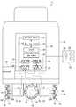
자율 이동 장치(1)는 유저의 원격 조작에 따라서 자기가 유도되고 있을 때에 SLAM을 이용하여 이동 공간(영역)의 환경 지도(장해물이 존재하는 영역과 존재하지 않는 영역을 나타낸 그리드 맵)를 작성함과 아울러 유도되어서 소정의 설정 포인트에 도달했을 때에 그때의 실제 자기 위치를 환경 지도 상의 설정 포인트의 위치 좌표로서 등록하는 기능을 갖는다(본 기능을 실행하는 모드를 「설치 모드」라고 칭한다). 또한, 자율 이동 장치(1)는 작성되어서 기억되어 있는 환경 지도 상의 설정 포인트를 이용해서 이동 경로를 계획함과 아울러 계획된 이동 경로를 따라 스타트 지점(자기의 현재지를 포함한다)에서부터 골 지점까지 자율적으로 이동하는 기능을 갖는다(본 기능을 실행하는 모드를 「반송 모드」라고 칭한다). 그 때문에, 자율 이동 장치(1)는 그 하부에 전동 모터(12) 및 상기 전동 모터(12)에 의해 구동되는 옴니휠(omni wheel;13)이 설치된 본체(10)와 주위에 존재하는 물체(예를 들면 벽이나 장해물 등)의 거리를 계측하는 레이저 레인지 파인더(20)와, 자율 이동 장치(1)를 유도함과 아울러 설정 포인트를 등록하는 조이스틱(21)을 구비하고 있다. 또한, 자율 이동 장치(1)는 설치 모드에 있어서의 환경 지도의 작성, 및 반송 모드에 있어서의 이동 경로의 계획 및 상기 이동 경로를 따른 자율 이동을 통합적으로 담당하는 전자 제어 장치(30)를 구비하고 있다. 이하, 각 구성 요소에 대해서 상세하게 설명한다.The autonomous
본체(10)는, 예를 들면 대략 바닥이 있는 원통 형상으로 형성된 금속제의 프레임이고, 이 본체(10)에 상술한 레이저 레인지 파인더(20), 및 전자 제어 장치(30) 등이 장착되어 있다. 또한, 본체(10)의 형상은 대략 바닥이 있는 원통 형상에 한정되지 않는다. 본체(10)의 하부에는 4개의 전동 모터(12)가 십자 형상으로 배치되어서 장착되어 있다. 4개의 전동 모터(12) 각각의 구동축(12A)에는 옴니휠(13)이 장착되어 있다. 즉, 4개의 옴니휠(13)은 동일 원주 상에 둘레 방향을 따라 90°씩 간격을 두고서 장착되어 있다.The
옴니휠(13)은 전동 모터(12)의 구동축(12A)을 중심으로 해서 회전하는 2개의 휠(14)과, 각 휠(14)의 외주에 전동 모터(12)의 구동축(12A)과 직교하는 축을 중심으로 해서 회전 가능하게 설치된 6개의 프리롤러(15)를 갖는 차륜이고, 모든 방향으로 이동 가능하게 한 것이다. 또한, 2개의 휠(14)은 위상을 30° 어긋나게 해서 장착되어 있다. 이러한 구성을 갖기 때문에, 전동 모터(12)가 구동되어서 휠(14)이 회전하면 6개의 프리롤러(15)는 휠(14)과 일체가 되어서 회전한다. 한편, 접지하고 있는 프리롤러(15)가 회전함으로써 옴니휠(13)은 그 휠(14)의 회전축에 평행한 방향으로도 이동할 수 있다. 그 때문에, 4개의 전동 모터(12)를 독립적으로 제어하여 4개의 옴니휠(13)의 각각의 회전 방향 및 회전 속도를 개별적으로 조절함으로써 자율 이동 장치(1)를 임의의 방향(모든 방향)으로 이동시킬 수 있다. 즉, 전동 모터(12) 및 옴니휠(13)은 특허청구범위에 기재된 이동 수단으로서 기능한다.The
4개의 전동 모터(12) 각각의 구동축(12A)에는 상기 구동축(12A)의 회전 각도(즉 구동량 또는 회전량)를 검출하는 인코더(16)가 장착되어 있다. 각 인코더(16)는 전자 제어 장치(30)와 접속되어 있고, 검출한 각 전동 모터(12)의 회전 각도를 전자 제어 장치(30)에 출력한다. 전자 제어 장치(30)는 입력된 각 전동 모터(12)의 회전 각도로부터 자율 이동 장치(1)의 이동량을 연산한다.The
레이저 레인지 파인더(20)는 자기의 정면 방향(전방)을 향하도록 해서 자율 이동 장치(1)의 전방부에 장착되어 있다. 레이저 레인지 파인더(20)는 레이저(검출 파)를 사출함과 아울러 사출한 레이저를 회전 미러로 반사시킴으로써 자율 이동 장치(1)의 주위를 중심각 240°의 부채 형상으로 수평 방향으로 주사한다. 그리고, 레이저 레인지 파인더(20)는, 예를 들면 벽이나 장해물 등의 물체에 의해 반사되어서 되돌아온 레이저를 검출하고, 레이저(반사파)의 검출 각도, 및 레이저를 사출한 후에 물체에 의해 반사되어서 되돌아올 때까지의 시간(전파 시간)을 계측함으로써 물체와의 각도 및 거리를 검출한다. 즉, 레이저 레인지 파인더(20)는 특허청구범위에 기재된 물체 정보 취득 수단으로서 기능한다. 또한, 레이저 레인지 파인더(20)는 전자 제어 장치(30)와 접속되어 있고, 검출한 주위 물체와의 거리 정보?각도 정보를 전자 제어 장치(30)에 출력한다.The
조이스틱(21)은 유저의 원격 조작에 따라서 자율 이동 장치(1)를 유도해서 이동시키기 위한 입력 장치이고, 자율 이동 장치(1)를 유도하기 위한 방향을 지시하는 막대 형상의 레버(22)와, 환경 지도 상의 설정 포인트를 등록하기 위한 등록 스위치(23)를 갖고 있다. 유저는 조이스틱(21)의 레버(22)를 조작함으로써 자율 이동 장치(1)에 대하여 이동 방향을 지시하여 자율 이동 장치(1)를 유도할 수 있다. 또한, 유저는 자율 이동 장치(1)를 유도하면서 소정의 설정 포인트(예를 들면 스타트 지점 후보, 목표 통과 지점 후보, 골 지점 후보)에 도달했을 때에 등록 스위치(23)를 누름으로써 그때의 자기 위치를 설정 포인트의 위치 좌표로서 등록할 수 있다. 또한 유저는, 설정 포인트의 속성 정보(예를 들면 엘리베이터 앞, 회의실 앞, 비상계단 앞 등)를 등록하도록 교시할 수 있다. 즉, 조이스틱(21)을 구성하는 레버(22)는 특허청구범위에 기재된 유도 수단으로서 기능하고, 등록 스위치(23)는 특허청구범위에 기재된 교시 수단으로서 기능한다. 또한, 조이스틱(21)은 전자 제어 장치(30)와 접속되어 있고, 유도 제어(방향 지시) 신호, 및 설정 포인트 등록 신호를 전자 제어 장치(30)에 출력한다.The
전자 제어 장치(30)는 자율 이동 장치(1)의 제어를 통합적으로 담당하는 것이다. 전자 제어 장치(30)는 연산을 행하는 마이크로프로세서, 마이크로프로세서에 각 처리를 실행시키기 위한 프로그램 등을 기억하는 ROM, 연산 결과 등의 각종 데이터를 일시적으로 기억하는 RAM, 및 그 기억 내용이 유지되는 백업 RAM 등으로 구성되어 있다. 또한, 전자 제어 장치(30)는 레이저 레인지 파인더(20), 조이스틱(21)과 마이크로프로세서를 전기적으로 접속시키는 인터페이스 회로, 및 전동 모터(12)를 구동하는 드라이버 회로 등도 구비하고 있다.The
전자 제어 장치(30)는 설치 모드를 실행함으로써 SLAM을 이용하여 이동 공간(영역)의 환경 지도를 작성함과 아울러 환경 지도 상의 설정 포인트의 위치 좌표를 등록한다. 또한, 전자 제어 장치(30)는 반송 모드를 실행함으로써 설정 포인트를 예를 들면 골 후보로 해서 이동 경로를 계획함과 아울러 계획된 이동 경로를 따라 스타트 지점(자기의 현재 위치)에서부터 골 지점까지 자율적으로 이동하도록 전동 모터(12)를 제어한다. 그 때문에, 전자 제어 장치(30)는 국소 지도 작성부(31), 자기 위치 추정부(32), 환경 지도 작성부(33), 기억부(34), 경로 계획부(35), 주행 제어부(36), 센서 정보 취득부(37), 및 장해물 회피 제어부(38) 등을 구비하고 있다. 또한, 이들 각 부는 상술한 하드웨어와 소프트웨어의 조합에 의해 구축된다.By executing the installation mode, the
국소 지도 작성부(31)는 레이저 레인지 파인더(20)로부터 센서 정보 취득부(37)를 통해서 판독된 주위 물체와의 거리 정보?각도 정보(특허청구범위에 기재된 물체 정보에 상당)에 의거하여 레이저 레인지 파인더(20)를 원점으로 한 자기 주변[레이저 레인지 파인더(20)의 검지 가능 범위 내]의 국소 지도를 작성한다. 즉, 국소 지도 작성부(31)는 특허청구범위에 기재된 국소 지도 작성 수단으로서 기능한다.The local
자기 위치 추정부(32)는 각 인코더(16)로부터 판독된 각 전동 모터(12)의 회전 각도에 따라서 산출된 자기의 이동량을 고려하여 환경 지도의 좌표계(절대 좌표계)로 좌표 변환한 국소 지도와 환경 지도를 대조하고, 그 결과에 의거하여 자기 위치를 추정한다. 즉, 자기 위치 추정부(32)는 특허청구범위에 기재된 자기 위치 추정 수단으로서 기능한다. 또한, 자기 위치 추정부(32)는 조이스틱(21)[등록 스위치(23)]으로부터 설정 포인트 등록 신호가 입력되었을 때에 그때의 자기 위치를 환경 지도 상의 설정 포인트의 위치 좌표로서 기억부(34)에 등록한다.The magnetic
환경 지도 작성부(33)는 유도 이동시(설치 모드 실행시)에 SLAM을 이용하여 이동 공간(영역)의 환경 지도를 작성한다. 즉, 환경 지도 작성부(33)는 특허청구범위에 기재된 환경 지도 작성 수단으로서 기능한다. 환경 지도는 자율 이동 장치(1)의 이동 영역의 그리드 맵이고, 벽면 등의 고정물(물체)의 위치가 기록되어 있다. 여기에서, 그리드 맵은 수평면을 소정 크기(예를 들면 1㎝×1㎝)의 셀(이하 「단위 그리드」 또는 간단히 「그리드」라고 한다)로 분할한 평면으로 이루어지는 지도이고, 단위 그리드마다 물체가 있는지 여부를 나타내는 물체 존재 확률 정보가 주어져 있다. 본 실시형태에서는 물체(장해물)가 있는 그리드에는 그 존재 확률에 따라서 「0~1」의 값이 부여되고, 물체(장해물)가 없는 그리드에는 그 존재 확률에 따라서 「0~-1」의 값이 부여된다. 또한 물체(장해물)의 유무가 불분명한 그리드에는 「0」이 부여된다.The environment
여기에서, 환경 지도의 작성 방법을 보다 구체적으로 설명하면, 환경 지도 작성부(33)는 우선 국소 지도 작성부(31)로부터 국소 지도를 취득함과 아울러 자기 위치 추정부(32)로부터 환경 지도 상의 자기 위치를 취득한다. 이어서, 환경 지도 작성부(33)는 레이저 레인지 파인더(20)를 원점으로 한 국소 지도를, 환경 지도 상의 자기 위치에 의거하여 레이저 레인지 파인더(20)를 원점으로 한 좌표계를 자기 위치를 바탕으로 환경 지도의 좌표계(이하 「절대 좌표계」라고 한다)로 좌표 변환함으로써 국소 지도(이하, 좌표 변환된 국소 지도를 「국소 지도@절대 좌표계」라고 한다)를 환경 지도에 투영한다. 그리고, 환경 지도 작성부(33)는 자율 이동 장치(1)가 유도되어서 이동하고 있는 동안에 이 처리를 반복하여 실행하여 국소 지도@절대 좌표계를 환경 지도에 순차적으로 더해 감으로써(보충해 감으로써) 이동 공간(영역) 전체의 환경 지도를 작성한다. 또한, 환경 지도 작성부(33)는 자율 이동시(반송 모드 실행시)에는 환경 지도의 작성?갱신을 정지한다.Herein, the method for creating an environment map will be described in more detail. First, the environment
기억부(34)는, 예를 들면 상술한 백업 RAM 등으로 구성되어 있고, 환경 지도 작성부(33)에 의해 작성된 환경 지도를 기억한다. 또한, 기억부(34)는 설정 포인트의 위치 좌표, 및 후술하는 경로 계획부(35)에 의해 계획되는 이동 경로 정보 등을 기억하는 기억 영역을 갖고 있고, 이들 정보도 기억한다. 즉, 기억부(34)는 특허청구범위에 기재된 기억 수단으로서 기능한다. 또한, 기억부(34)는 SRAM이나 EEPROM 등이어도 된다.The
경로 계획부(35)는 자기의 자기 위치와 유저가 선택한 설정 포인트[기억부(34)에 기억되어 있는 환경 지도 상의 설정 포인트(예를 들면 스타트 지점, 목표 통과 지점, 골 지점)]간을 접속시킴으로써 자율 이동 장치(1)의 이동 경로를 계획한다. 또한, 설정 포인트를 골 지점으로 해서 이동 경로를 계획할 경우, 자기 위치를 파악할 수 있기 때문에 반드시 설정 포인트끼리를 접속할 필요는 없다. 즉, 경로 계획부(35)는 특허청구범위에 기재된 경로 계획 수단으로서 기능한다. 보다 상세하게는, 경로 계획부(35)는 예를 들면 우선 환경 지도에 포함되는 장해물 영역의 윤곽을 밍코프스키(Minkowski) 합을 이용하여 자기의 반경만큼 확장해서 확장 장해물 영역을 작성하고, 상기 확장 장해물 영역을 제외한 영역을 장해물과 접촉하지 않고 이동할 수 있는 이동 가능 영역으로서 추출한다. 이어서, 경로 계획부(35)는 힐디치(Hilditch)의 세선화법을 이용하여 추출한 이동 가능 영역을 세선화한다. 그리고, 경로 계획부(35)는 세선화된 이동 가능 영역 중에서 A* 알고리즘(A스타 알고리즘)을 이용하여 설정 포인트(스타트 지점, 목표 통과 지점, 골 지점)간을 연결하는 최단 경로를 탐색함으로써 이동 경로를 계획한다.The
주행 제어부(36)는 설치 모드 실행시에 조이스틱(21)[레버(22)]으로부터 입력되는 유도 제어(방향 지시) 신호(즉 유저의 조작)에 따라서 자율 이동 장치(1)가 이동하도록(유도되도록) 전동 모터(12)를 구동한다. 한편, 주행 제어부(36)는 반송 모드 실행시에 장해물을 회피하면서 계획된 이동 경로를 따라 자기를 골 지점까지 자율 이동시키도록 전동 모터(12)를 제어한다. 즉, 주행 제어부(36)는 특허청구범위에 기재된 제어 수단으로서 기능한다. 여기에서, 본 실시형태에서는 반송 모드 실행시에 장해물을 회피하면서 이동 경로를 따라 자기를 골 지점까지 자율 이동시키는 제어 방법으로서 가상 포텐셜법을 채용했다. 이 가상 포텐셜법은 골 지점에 대한 가상적인 인력 포텐셜장과, 회피해야 할 장해물에 대한 가상적인 척력 포텐셜장을 작성해서 중합함으로써 장해물과의 접촉을 회피하면서 골 지점으로 향하는 방법이다. 보다 구체적으로는, 주행 제어부(36)는 우선 자기 위치에 의거하여 골 지점으로 향하기 위한 가상 인력을 계산한다. 한편, 장해물 회피 제어부(38)에 의해 자기 위치, 이동 속도, 및 장해물의 위치 및 속도에 의거하여 장해물을 회피하기 위한 가상 척력이 산출된다. 이어서, 주행 제어부(36)는 얻어진 가상 인력과, 가상 척력을 벡터 합성함으로써 가상 힘벡터(force vector)를 계산한다. 그리고, 주행 제어부(36)는 얻어진 가상 힘벡터에 따라서 전동 모터(12)[옴니휠(13)]를 구동함으로써 장해물을 회피하면서 골 지점으로 이동하도록 자기의 주행을 컨트롤한다.The
이어서, 도 2, 도 3을 아울러 이용하여 자율 이동 장치(1)의 동작에 대하여 설명한다. 도 2는 자율 이동 장치(1)에 의한 설치 처리(설치 모드)의 처리 순서를 나타내는 플로우차트이다. 또한, 도 3은 자율 이동 장치(1)에 의한 반송 처리(반송 모드)의 처리 순서를 나타내는 플로우차트이다. 도 2, 도 3에 나타내어지는 각 처리는 주로 전자 제어 장치(30)에 의해 행하여지는 것이고, 유저로부터의 조작에 의해 기동되고, 실행된다. 또한, 도 2에 나타내어지는 설치 처리(설치 모드)는 도 3에 나타내어지는 반송 처리(반송 모드)에 앞서 실행된다.Next, the operation of the
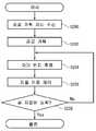
우선, 도 2에 나타내어지는 설치 처리(설치 모드)의 처리 순서에 대하여 설명한다. 또한, 설치 처리를 개시하기 전에 사전 준비로서 유도 경로 상에 놓인 가동물(可動物)을 배제해 두는 것이 바람직하다. 또한, 자율 이동 장치(1)를 유도하면서 환경 지도를 작성하고 있을 때에는 이동체가 레이저 레인지 파인더(20)의 검지 범위에 들어가지 않도록 하는 것이 바람직하다.First, the processing procedure of the installation process (installation mode) shown in FIG. 2 is demonstrated. In addition, it is preferable to exclude the animals placed on the induction route as preparation before starting the installation process. In addition, it is preferable that the moving object does not enter the detection range of the
스텝 S100에 있어서, 유저로부터의 환경 지도 작성 개시 지시가 접수되면 자율 이동 장치(1)가 유도되어서 이동을 개시한다. 이어지는 스텝 S102에서는 SLAM을 이용하여 이동 영역의 환경 지도가 작성(또는 갱신)된다. 또한, 환경 지도의 작성 방법은 상술한 바와 같으므로 여기에서는 상세한 설명을 생략한다.In step S100, upon receipt of an instruction to start environment mapping from the user, the autonomous
이어서, 스텝 S104에서는 조이스틱(21)[레버(22)]으로부터 입력되는 유도 제어(방향 지시) 신호(즉 유저의 조작)에 따라서 자율 이동 장치(1)가 유도되어서 이동한다.Subsequently, in step S104, the autonomous moving
이어서, 스텝 S106에서는 조이스틱(21)[등록 스위치(23)]으로부터 설정 포인트 등록 신호가 입력되었는지 여부에 대한 판단이 행하여진다. 여기에서, 설정 포인트 등록 신호가 입력되었을 경우에는 스텝 S108에 있어서 그 지점의 자기 위치가 환경 지도 상의 설정 포인트의 위치 좌표로서 등록된다. 한편, 설정 포인트 등록 신호가 입력되어 있지 않을 때에는 스텝 S110으로 처리가 이행한다.Next, in step S106, a determination is made as to whether or not a set point registration signal is input from the joystick 21 (registration switch 23). Here, when the set point registration signal is input, in step S108 the magnetic position of the point is registered as the position coordinate of the set point on the environment map. On the other hand, when the set point registration signal is not input, the process shifts to step S110.
스텝 S110에서는 유저로부터의 환경 지도 작성 종료 지시가 접수되었는지 여부에 대한 판단이 행하여진다. 여기에서, 환경 지도 작성 종료 지시가 접수되어 있지 않은 경우에는 스텝 S102로 처리가 이행하고, 환경 지도 작성 종료 지시가 접수될 때까지 상술한 스텝 S102~스텝 S108의 처리가 반복하여 실행된다. 한편, 환경 지도 작성 종료 지시가 접수되었을 때에는 작성된 설정 포인트를 포함하는 환경 지도가 기억되고, 설치 처리(설치 모드)가 종료된다.In step S110, a determination is made as to whether or not an instruction to end the environment mapping preparation from the user has been received. Here, when the environment mapping preparation end instruction is not received, the process shifts to step S102, and the above-described processes of step S102 to step S108 are repeatedly executed until the environment mapping preparation end instruction is received. On the other hand, when the environment map preparation end instruction is received, the environment map including the created set point is stored, and the installation process (installation mode) is finished.
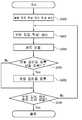
이어서, 자율 이동 장치(1)에 의한 반송 처리(반송 모드)의 처리 순서에 대하여 설명한다. 우선, 스텝 S200에서 유저로부터의 경로 계획 지시가 접수되면 스텝 S202에서 자율 이동 장치(1)의 이동 경로가 계획된다. 즉, 유저에 의해 기억부(34)에 기억되어 있는 환경 지도 상의 설정 포인트(스타트 지점, 목표 통과 지점, 골 지점) 중 적어도 1개가 지정됨으로써 자율 이동 장치(1)의 이동 경로가 계획된다. 또한, 경로 계획의 방법에 대해서는 상술한 바와 같으므로 여기에서는 상세한 설명을 생략한다.Next, the processing procedure of the conveyance process (conveyance mode) by the autonomous moving
이어서, 스텝 S204에서는 자기 위치 추정이 행하여진다. 즉, 레이저 레인지 파인더(20)의 검출 결과로부터 국소 지도 작성부(31)에 의해 국소 지도가 취득됨과 아울러 인코더(16)로부터 판독된 각 전동 모터(12)의 회전 각도에 따라서 산출된 자기의 이동량을 고려하여 복수의 가상 자기 위치가 가정된다. 취득된 국소 지도는 각 가상의 자기 위치에 있어서의 국소 지도@절대 좌표계로 변환되어 복수의 국소 지도@절대 좌표계가 취득된다. 이 복수의 국소 지도@절대 좌표계의 각각과 환경 지도가 대조되어 각 가상의 자기 위치에 있어서의 우도(尤度)가 연산되고, 각 가상의 자기 위치에 있어서의 우도에 대하여 베이시안 필터링이 적용되어서(사전 확률과 우도가 승산되어서) 각 가상의 자기 위치에 있어서의 사후 확률이 산출된다. 산출된 복수의 사후 확률 중 가장 높은 것이 추출되고, 이것에 대응하는 가상의 자기 위치가 참된 자기 위치로서 추정된다. 이 가장 높은 사후 확률의 추출에서는 복수의 사후 확률 분포 중에서 가장 높은 피크를 갖는 사후 확률을 추출해도 되고, 또는 가장 기대치가 높은 사후 확률을 추출해도 된다.Next, in step S204, magnetic position estimation is performed. That is, a local map is acquired by the local
이어서, 스텝 S206에서는 자율 이동 제어가 실행되고, 장해물을 회피하면서 계획된 이동 경로를 따라 자기를 골 지점까지 자율 이동시키도록 전동 모터(12)가 제어된다. 상술한 바와 같이, 본 실시형태에서는 장해물을 회피하면서 이동 경로를 따라 자기를 골 지점까지 이동시키는 제어 방법으로서 가상 포텐셜법을 채용했다. 또한, 가상 포텐셜법에 대해서는 상술한 바와 같으므로 여기에서는 상세한 설명을 생략한다.Subsequently, in step S206, autonomous movement control is executed, and the
이어지는 스텝 S208에서는 자기가 골 지점에 도착했는지 여부에 대한 판단이 행하여진다. 여기에서, 자기가 골 지점에 도착하지 않은 경우에는 스텝 S204로 처리가 이행되고, 골 지점에 도착할 때까지 상술한 스텝 S204(자기 위치 추정) 및 스텝 S206(자율 이동 제어)의 처리가 반복하여 실행된다. 한편, 자기가 골 지점에 도착했을 때에는 반송 처리(반송 모드)가 종료한다.In a subsequent step S208, a judgment is made as to whether or not he has reached the goal point. Here, in the case where the self does not reach the goal point, the process proceeds to step S204, and the processes of step S204 (self position estimation) and step S206 (autonomous movement control) described above are repeatedly executed until the goal point is reached. do. On the other hand, when the person reaches the goal point, the conveyance processing (transfer mode) ends.
본 실시형태에 의하면, 유저의 조작에 따라서 자기가 유도되고 있을 때에 환경 지도가 작성됨과 아울러 유도되어서 소정의 설정 포인트에 도달했을 때에 그때의 실제의 자기 위치가 환경 지도 상의 설정 포인트의 위치 좌표로서 등록된다. 그 때문에, 자율 이동 장치를 이동시키고 싶은 경로를 따라 유도하면서 설정 포인트를 등록하는 것만으로 실제 이동 환경에 대한 어긋남이 없는 설정 포인트를 포함하는 환경 지도를 작성할 수 있다.According to the present embodiment, an environment map is created when self is induced according to the user's operation, and when the guidance is induced and a predetermined set point is reached, the actual self position at that time is registered as the position coordinate of the set point on the environment map. do. Therefore, it is possible to create an environment map including the set points without misalignment with the actual moving environment simply by registering the set points while guiding the autonomous mobile devices along the path to be moved.
또한, 본 실시형태에 의하면 작성되어서 기억되어 있는 환경 지도 상의 설정 포인트가 지정되어서 이동 경로가 계획되고, 그 이동 경로를 따라 자율 이동하도록 제어된다. 그 때문에, 예를 들면 설정 포인트를 스타트 지점 및/또는 골 지점으로 해서 이동 경로를 계획하면 실제 이동 영역과의 어긋남이 적은 이동 경로를 계획하고, 재현성 좋게 자율 이동할 수 있다. 이상의 결과, 본 실시형태에 의하면 환경 지도 상의 설정 포인트를 포함하는 신뢰성이 높은 환경 지도를 간이하게 작성할 수 있고, 또한 상기 환경 지도를 이용하여 보다 정확한 자율 이동을 행할 수 있게 된다.Moreover, according to this embodiment, the set point on the environment map which is created and stored is specified, and a movement route is planned and it is controlled to autonomously move along the movement route. Therefore, for example, if the movement path is planned with the set point as the start point and / or the goal point, the movement path with less deviation from the actual movement area can be planned, and autonomous movement can be performed with high reproducibility. As a result, according to the present embodiment, a highly reliable environmental map including a set point on the environmental map can be easily created, and more accurate autonomous movement can be performed using the environmental map.
[제 2 실시형태][Second Embodiment]
이어서, 도 4를 이용하여 제 2 실시형태에 의한 자율 이동 장치(2)의 구성에 대하여 설명한다. 도 4는 자율 이동 장치(2)의 구성을 나타내는 블럭도이다. 또한, 도 4에 있어서 제 1 실시형태와 동일하거나 또는 동등한 구성요소에 대해서는 동일한 부호가 붙여져 있다.Next, the structure of the
자율 이동 장치(2)는 상술한 전자 제어 장치(30) 대신에 전자 제어 장치(40)를 구비하고 있는 점에서 자율 이동 장치(1)와 다르다. 이 전자 제어 장치(40)는 차분 지도 작성부(41), 동적 환경 지도 작성부(42)를 더 갖는 점, 및 자기 위치 추정부(32), 기억부(34) 대신에 자기 위치 추정부(43), 기억부(44)를 갖고 있는 점에서 전자 제어 장치(30)와 다르다. 이하, 이들 자율 이동 장치(1)와 다른 구성 요소에 대해서 상세하게 설명한다. 또한, 그 이외의 구성에 대해서는 자율 이동 장치(1)와 동일하거나 또는 동등하므로 여기에서는 설명을 생략한다.The autonomous
동적 환경 지도 작성부(42)는 자기가 이동 경로를 따라 자율 이동할 때에 후술하는 차분 지도 작성부(41)에 의해 작성되는 차분 지도와, 상술한 환경 지도 작성부(33)에 의해 작성되고, 기억부(44)에 기억되어 있는 환경 지도(이하 「정적 환경 지도」라고 한다)를 그리드마다 더해서 현재의 실환경을 나타내는 동적 환경 지도를 작성한다. 즉, 동적 환경 지도 작성부(42)는 특허청구범위에 기재된 동적 환경 지도 작성 수단으로서 기능한다. 또한, 정적 환경 지도의 각 그리드에 계수 P1(예를 들면 0.5)을 곱한 것과, 차분 지도의 각 그리드에 계수 P2(예를 들면 1.0)를 곱한 것을 그리드마다 더함으로써 동적 환경 지도를 작성하도록 해도 된다.The dynamic environment
차분 지도 작성부(41)는 자기가 이동 경로를 따라 자율 이동할 때에 동적 환경 지도와 정적 환경 지도의 차분, 즉 이동 영역 내의 물체 변화 정도를 나타내는 차분 지도를 작성?갱신한다. 보다 구체적으로는, 차분 지도 작성부(41)는 동적 환경 지도(t-1 : 전회 값)와 국소 지도@절대 좌표계(t : 금회 값)를 그리드마다 더한 결과와, 정적 환경 지도의 차분을 그리드마다 구함으로써 차분 지도(t : 금회 값)를 작성(갱신)한다. 즉, 차분 지도 작성부(41)는 특허청구범위에 기재된 차분 지도 작성 수단으로서 기능한다. 또한, 차분 지도의 좌표계는 정적 환경 지도와 동일(절대 좌표)하다. 또한, 후술하는 기억부(44)에 기억되는 차분 지도는 자기의 주변부만이고, 자기가 이동하는데 따라 통과한 영역의 차분 지도는 기억부(44)로부터 소거된다. 또한, 동적 환경 지도와 국소 지도@절대 좌표계를 그리드마다 더한 결과와, 정적 환경 지도의 각 그리드에 계수 P1(예를 들면 0.5)을 곱한 것의 차분을 그리드마다 구함으로써 차분 지도를 작성(갱신)하도록 해도 된다. 이 경우, 상기 계수 P1을 고려하여 동적 환경 지도의 상한값을 「0.5」 하한값을 「-0.5」로 제한한다.The difference
기억부(44)는 정적 환경 지도에 추가하여 차분 지도를 기억하는 기억 영역을 갖고 있어, 정적 환경 지도 및 차분 지도를 기억한다. 또한, 동적 환경 지도는 자기 위치의 추정(후술)이 행하여지는 동안만 일시적으로 작성?기억되고, 기억부(44)에는 항구적으로는 기억되지 않는다.The
자기 위치 추정부(43)는 자기가 이동 경로를 따라 자율 이동할 때에 인코더(16)로부터 판독된 각 전동 모터(12)의 회전 각도에 따라서 산출된 자기의 이동량을 고려하여 정적 환경 지도 및 동적 환경 지도 각각과 국소 지도@절대 좌표계를 대조(그리드마다 매칭)하고, 그 대조 결과에 의거하여(상술한 스텝 S204와 마찬가지의 처리를 실행하여) 자기 위치를 추정한다. 보다 구체적으로 설명하면, 우선 자기 위치 추정부(43)는 국소 지도@절대 좌표계에 포함되는 그리드의 값(물체 존재 확률)이 1.0인 그리드를 정적 환경 지도 및 동적 환경 지도에 투영하고, 국소 지도@절대 좌표계의 그리드 값과, 상기 그리드에 대응하는 정적 환경 지도 및 동적 환경 지도 각각의 그리드 값을 대조한다. 그리고, 그리드마다 보다 일치도가 높은 쪽의 지도의 그리드 값을 채용하고, 채용된 그리드 값의 평균을 그 위치(가상의 자기 위치)의 스코어(우도)로 한다. 예를 들면, 국소 지도@절대 좌표계의 그리드 값이 1.0이고, 정적 환경 지도의 그리드 값이 1.0, 동적 환경 지도의 그리드 값이 0.5인 경우에는 정적 환경 지도의 그리드 값 1.0이 채용된다. 또한, 예를 들면 국소 지도@절대 좌표계의 그리드 값이 1.0이고, 정적 환경 지도의 그리드 값이 -1.0, 동적 환경 지도의 그리드 값이 0.3인 경우에는 동적 환경 지도의 그리드 값 0.3이 채용된다. 그리고, 예를 들면 4개의 그리드에 대해서 채용된 그리드 값이 1.0, 1.0, 0.3, 0.3이었을 경우에는 그들 평균값 0.65가 가상의 자기 위치에서의 스코어가 된다. 마찬가지로 해서, 가상의 자기 위치를 A점, B점, C점, D점, … 으로 해서 스코어를 구해 가고, 가장 스코어가 높은 위치를 자기 위치라고 추정한다. 여기에서, 자기 위치의 스코어(우도)를 구할 때에는 그리드의 값(물체 존재 확률)이 1.0인 그리드만을 대상으로 하는 것은 아니고, 예를 들면 그리드 값(물체 존재 확률)이 -1.0인 그리드를 대상으로 해서 스코어를 구해도 되고, 모든 그리드를 대상으로 해서 스코어를 구해도 된다.The magnetic
이어서, 도 5를 참조하면서 자율 이동 장치(2)의 동작에 대하여 설명한다. 도 5는 자율 이동 장치(2)에 의한 반송 처리(반송 모드)의 처리 순서를 나타내는 플로우차트이다. 도 5에 나타내어지는 반송 처리는 주로 전자 제어 장치(40)에 의해 행하여지는 것이고, 유저로부터의 조작에 의해 기동되고, 실행된다. 또한, 자율 이동 장치(2)에 의한 설치 처리(설치 모드)의 처리 순서는 상술한 자율 이동 장치(1)의 경우와 동일하므로, 여기에서는 설명을 생략한다.Next, the operation of the autonomous
스텝 S300에 있어서, 유저로부터의 경로 계획 지시가 접수되면 스텝 S302에서 자율 이동 장치(2)의 이동 경로가 계획된다. 즉, 기억부(44)에 기억되어 있는 환경 지도 상의 설정 포인트(스타트 지점, 목표 통과 지점, 골 지점)가 지정됨으로써 자율 이동 장치(2)의 이동 경로가 계획된다. 또한, 경로 계획의 방법에 대해서는 상술한 바와 같으므로, 여기에서는 상세한 설명을 생략한다.In step S300, when the route planning instruction from the user is received, the movement route of the autonomous
이어서, 스텝 S304에서는 자기 위치 추정이 행하여진다. 즉, 인코더(16)로부터 판독된 각 전동 모터(12)의 회전 각도에 따라서 산출된 자기의 이동량을 고려하여 정적 환경 지도 및 동적 환경 지도 각각과 국소 지도@절대 좌표계가 대조(매칭)되고, 그 대조 결과에 의거하여(상술한 스텝 S204와 마찬가지의 처리가 실행되어) 자기 위치가 추정된다. 또한, 자기 위치의 추정 방법에 대해서는 상술한 바와 같으므로, 여기에서는 상세한 설명을 생략한다.Next, in step S304, magnetic position estimation is performed. That is, each of the static environment map and the dynamic environment map and the local map @ absolute coordinate system are collated (matched) in consideration of the amount of movement of the magnet calculated according to the rotation angle of each
이어서, 스텝 S306에서는 동적 환경 지도(t-1 : 전회 값)와 국소 지도@절대 좌표계(t : 금회 값)의 가산 결과와, 정적 환경 지도의 차분으로부터 차분 지도(t : 금회 값)가 작성(갱신)된다. 이어지는 스텝 S308에서는 정적 환경 지도와 차분 지도(t : 금회 값)가 그리드마다 더해져서 동적 환경 지도(t : 금회 값)가 작성된다.Subsequently, in step S306, a difference map (t: current value) is created from the addition result of the dynamic environment map (t-1: previous value) and the local map @ absolute coordinate system (t: current value) and the difference of the static environment map. Update). In a subsequent step S308, the static environment map and the difference map (t: current value) are added for each grid to generate a dynamic environment map (t: current value).
이어서, 스텝 S310에서는 자율 이동 제어가 실행되고, 장해물을 회피하면서 계획된 이동 경로를 따라 자기를 골 지점까지 자율 이동시키도록 전동 모터(12)가 제어된다. 상술한 바와 같이, 본 실시형태에서는 장해물을 회피하면서 이동 경로를 따라 자기를 골 지점까지 이동시키는 제어 방법으로서 가상 포텐셜법을 채용했다. 또한, 가상 포텐셜법에 대해서는 상술한 바와 같으므로, 여기에서는 상세한 설명을 생략한다.Subsequently, in step S310, autonomous movement control is executed, and the
이어지는 스텝 S312에서는 자기가 골 지점에 도착했는지 여부에 대한 판단이 행하여진다. 여기에서, 자기가 골 지점에 도착하지 않은 경우에는 스텝 S304로 처리가 이행하고, 골 지점에 도착할 때까지 상술한 스텝 S304~스텝 S310의 처리가 반복하여 실행된다. 한편, 자기가 골 지점에 도착했을 때에는 반송 처리(반송 모드)가 종료한다.In a subsequent step S312, a judgment is made as to whether or not he has reached the goal point. Here, in the case where the self does not reach the goal point, the process shifts to step S304, and the above-described processes of step S304 to step S310 are repeatedly executed until the goal point is reached. On the other hand, when the person reaches the goal point, the conveyance processing (transfer mode) ends.
본 실시형태에 의하면, 이동 경로를 따라 자율 이동할 때에 이동 영역 내의 물체 변화 정도를 나타내는 차분 지도가 작성됨과 아울러 환경 지도와 차분 지도의 가산 결과로부터 동적 환경 지도가 작성된다. 또한 환경 지도 및 동적 환경 지도 각각과 국소 지도@절대 좌표계가 대조되고, 그 대조 결과에 의거하여(상술한 스텝 S204와 마찬가지의 처리가 행하여져) 자기 위치가 추정된다. 자율 이동 중에는 차분 지도만이 갱신되고, 신뢰도가 높은 환경 지도는 수정되지 않고 유지되기 때문에, 예를 들면 추정된 자기 위치가 실제의 자기 위치와 어긋나 있는 경우 등에 신뢰도가 높은 환경 지도를 잘못해서 수정해버리는 것을 방지할 수 있다. 또한, 예를 들면 추정된 자기 위치가 실제의 자기 위치와 일시적으로 어긋났다고 하여도 복귀할 수 있게 된다. 또한, 이동 영역 내에 환경 변화가 있었을 경우, 예를 들면 이동체가 자기의 근방을 통과하거나, 통로 상에 새로운 물체가 놓여지거나 했을 경우에는 그 변화가 차분 지도로서 추출되고, 동적 환경 지도에 반영된다. 그 때문에, 이동 환경의 다이나믹한 환경 변화에 대응할 수 있게 된다.According to this embodiment, the difference map which shows the degree of object change in a movement area at the time of autonomous movement along a movement path is created, and a dynamic environment map is created from the addition result of an environment map and a difference map. In addition, each of the environment map and the dynamic environment map and the local map @ absolute coordinate system are collated, and the magnetic position is estimated based on the collation result (the same processing as in step S204 described above). During the autonomous movement, only the difference map is updated and the highly reliable environmental map is maintained without modification. For example, if the estimated magnetic position is out of alignment with the actual magnetic position, the high-confidence environmental map is incorrectly corrected. You can prevent throwing away. Further, for example, even if the estimated magnetic position is temporarily shifted from the actual magnetic position, it is possible to return. In addition, when there is an environmental change in the moving area, for example, when the moving object passes near oneself or when a new object is placed on the passage, the change is extracted as a difference map and reflected in the dynamic environment map. Therefore, it is possible to cope with the dynamic environment change of the mobile environment.
이상, 본 발명의 실시형태에 대하여 설명했지만, 본 발명은 상기 실시형태에 한정되는 것은 아니고 여러 가지 변형이 가능하다. 예를 들면, 상기 실시형태에서는 자율 이동 장치(1,2)를 원격 조작하기 위한 입력 장치로서 조이스틱(21)을 사용했지만, 자율 이동 장치(1,2)를 유도함과 아울러 설정 포인트를 등록할 수 있으면 되고, 키보드나 텐키패드 등 다른 형식의 리모트 콘트롤러 등을 이용해도 된다.As mentioned above, although embodiment of this invention was described, this invention is not limited to the said embodiment, A various deformation | transformation is possible. For example, although the
상기 실시형태에서는 레이저 레인지 파인더(20)를 이용하여 장해물과의 거리를 측정했지만, 레이저 레인지 파인더 대신에 또는 추가하여, 예를 들면 스테레오 카메라, 초음파 센서 등을 사용하는 구성으로 해도 된다.In the said embodiment, although the distance with the obstacle was measured using the
상기 실시형태에서는 차륜으로서 전방위로 이동 가능한 옴니휠(13)을 채용했지만, 통상의 차륜(조타륜 및 구동륜)을 사용하는 구성으로 해도 된다.In the above embodiment, the
[제 3 실시형태][Third embodiment]
이어서, 도 6을 이용하여 제 3 실시형태에 의한 자율 이동 장치(3)의 구성에 대하여 설명한다. 도 6은 자율 이동 장치(3)의 구성을 나타내는 블럭도이다.Next, the structure of the
자율 이동 장치(3)는 복수의 부분 지도로 이루어지는 환경 지도를 작성하는 환경 지도 작성 기능, 복수의 부분 지도에 걸쳐지는 이동 경로를 계획하는 경로 계획 기능, 및 복수의 부분 지도에 걸쳐서 이동 경로를 따라 이동하는 자율 이동 기능을 갖는다. 보다 상세하게는, 자율 이동 장치(3)는 유저의 원격 조작에 따라서 자기가 유도되고 있을 때에 SLAM을 이용하여 이동 영역의 환경 지도(장해물이 존재하는 영역과 존재하지 않는 영역을 나타낸 그리드 맵)를 구성하는 복수의 부분 지도를 작성함과 아울러, 유도되어서 부분 지도간의 연결점(이하 「연결 포인트」라고 하고, 유저가 지정한다)에 도달했을 때에 그때의 자기 위치를 부분 지도 상의 연결 포인트의 위치 좌표로서 등록하는 기능을 갖는다(본 기능을 실행하는 모드를 「설치 모드」라고 칭한다). 또한, 자율 이동 장치(3)는 작성된 복수의 부분 지도마다 이동 가능 영역을 추출하고, 위상 지도를 이용하여 연결하고, 위상 지도 상에서 최단 경로 탐색을 행한 후에 다시 분할하고, 부분 지도마다의 이동 경로를 계획하는 기능을 갖는다. 또한, 자율 이동 장치(3)는 계획된 이동 경로를 따라 스타트 지점으로부터 골 지점까지 복수의 부분 지도에 걸쳐서 자율 이동하는 기능을 갖는 다(본 기능을 실행하는 모드를 「반송 모드」라고 칭한다).The autonomous
그 때문에, 자율 이동 장치(3)는 그 하부에 전동 모터(12) 및 상기 전동 모터(12)에 의해 구동되는 옴니휠(13)이 설치된 본체(10)와, 주위에 존재하는 물체(예를 들면 벽이나 장해물 등)와의 거리를 계측하는 레이저 레인지 파인더(20)와, 자율 이동 장치(3)를 유도함과 아울러 연결 포인트를 등록하는 조이스틱(21)을 구비하고 있다. 또한, 자율 이동 장치(3)는 복수의 부분 지도(환경 지도) 작성, 복수의 부분 지도에 걸치는 이동 경로의 계획, 및 상기 이동 경로를 따른 자율 이동을 통합적으로 담당하는 전자 제어 장치(50)를 구비하고 있다. 이하, 각 구성 요소에 대해서 상세하게 설명한다.Therefore, the
본체(10)는, 예를 들면 대략 바닥이 있는 원통 형상으로 형성된 금속제 프레임이고, 이 본체(10)에 상술한 레이저 레인지 파인더(20), 및 전자 제어 장치(50) 등이 장착되어 있다. 또한, 본체(10)의 형상은 대략 바닥이 있는 원통 형상에 한정되지 않는다. 본체(10)의 하부에는 4개의 전동 모터(12)가 십자 형상으로 배치되어서 장착되어 있다. 4개의 전동 모터(12)의 각각의 구동축(12A)에는 옴니휠(13)이 장착되어 있다. 즉, 4개의 옴니휠(13)은 동일 원주 상에 둘레 방향을 따라 90°씩 간격을 두고서 장착되어 있다.The
옴니휠(13)은 전동 모터(12)의 구동축(12A)을 중심으로 해서 회전하는 2개의 휠(14)과, 각 휠(14)의 외주에 전동 모터(12)의 구동축(12A)과 직교하는 축을 중심으로 해서 회전 가능하게 설치된 6개의 프리롤러(15)를 갖는 차륜이고, 모든 방향으로 이동 가능하게 한 것이다. 또한, 2개의 휠(14)은 위상을 30° 어긋나게 해서 장착되어 있다. 이러한 구성을 갖기 때문에 전동 모터(12)가 구동되어서 휠(14)이 회전하면 6개의 프리롤러(15)는 휠(14)과 일체가 되어서 회전한다. 한편, 접지하고 있는 프리롤러(15)가 회전함으로써 옴니휠(13)은 그 휠(14)의 회전축에 평행한 방향으로도 이동할 수 있다. 그 때문에, 4개의 전동 모터(12)를 독립적으로 제어하여 4개의 옴니휠(13)의 각각의 회전 방향 및 회전 속도를 개별적으로 조절함으로써 자율 이동 장치(3)를 임의의 방향(모든 방향)으로 이동시킬 수 있다. 즉, 전동 모터(12) 및 옴니휠(13)은 특허청구범위에 기재된 이동 수단으로서 기능한다.The
4개의 전동 모터(12) 각각의 구동축(12A)에는 상기 구동축(12A)의 회전 각도(즉 구동량 또는 회전량)를 검출하는 인코더(16)가 장착되어 있다. 각 인코더(16)는 전자 제어 장치(50)와 접속되어 있고, 검출한 각 전동 모터(12)의 회전 각도를 전자 제어 장치(50)에 출력한다. 전자 제어 장치(50)는 입력된 각 전동 모터(12)의 회전 각도로부터 자율 이동 장치(3)의 이동량을 연산한다.The
레이저 레인지 파인더(20)는 자기의 정면 방향(전방)을 향하도록 해서 자율 이동 장치(3)의 전방부에 장착되어 있다. 레이저 레인지 파인더(20)는 레이저(검출 파)를 사출함과 아울러 사출한 레이저를 회전 미러로 반사시킴으로써 자율 이동 장치(3)의 주위를 중심각 240°의 부채 형상으로 수평 방향으로 주사한다. 그리고, 레이저 레인지 파인더(20)는, 예를 들면 벽이나 장해물 등의 물체에 의해 반사되어서 되돌아온 레이저를 검출하고, 레이저(반사파)의 검출 각도, 및 레이저를 사출한 후에 물체에 의해 반사되어서 되돌아올 때까지의 시간(전파 시간)을 계측함으로써 물체와의 각도 및 거리를 검출한다. 즉, 레이저 레인지 파인더(20)는 특허청구범위에 기재된 취득 수단으로서 기능한다. 또한, 레이저 레인지 파인더(20)는 전자 제어 장치(50)와 접속되어 있고, 검출한 주위 물체와의 거리 정보?각도 정보를 전자 제어 장치(50)에 출력한다.The
조이스틱(21)은 유저의 원격 조작에 따라서 자율 이동 장치(3)를 유도해서 이동시키기 위한 입력 장치이고, 자율 이동 장치(3)를 유도하기 위한 방향을 지시하는 막대 형상의 레버(22)와, 부분 지도 상의 연결 포인트를 등록하기 위한 등록 스위치(23)를 갖고 있다. 유저는 조이스틱(21)의 레버(22)를 조작함으로써 자율 이동 장치(3)에 대하여 이동 방향을 지시하고, 자율 이동 장치(3)를 유도할 수 있다. 또한, 유저는 자율 이동 장치(3)를 유도하면서 부분 지도의 연결 포인트에 도달했을 때에 등록 스위치(23)를 누름으로써 그때의 자기 위치를 연결 포인트의 위치 좌표로서 등록할 수 있다. 즉, 조이스틱(21)을 구성하는 등록 스위치(23)는 특허청구범위에 기재된 설정 수단으로서 기능한다. 또한, 조이스틱(21)은 전자 제어 장치(50)와 접속되어 있고, 유도 제어(방향 지시) 신호, 및 연결 포인트 등록 신호를 전자 제어 장치(50)에 출력한다.The
터치스크린(24)은 액정 디스플레이(LCD) 등으로 이루어지는 표시부(25)와, 표시부(25) 상의 유저의 터치 조작(입력)을 검출하는 터치패널 등으로 이루어지는 조작 입력부(26)를 갖고서 구성되는 입력 장치이다. 표시부(25)는, 예를 들면 연결 포인트를 등록할 때, 및 연결 포인트를 선택할 때에 연결 포인트를 포함하는 부분 지도 및 연결 포인트의 좌표 정보 등을 표시한다. 또한, 표시부(25)는 연결 포인트 및 스타트 지점/골 지점 등을 선택하는 유저로부터의 조작을 접수하기 위한 각종 스위치 등을 표시한다. 여기에서, 표시부(25)에 표시되는 연결 포인트의 선택 화면의 일례를 도 7에 나타낸다. 도 7에 나타낸 화면에서는 선택된 연결 포인트의 좌표 정보, 및 연결 포인트의 연결 관계 등이 표시되어 있다.The
조작 입력부(26)는 표시부(25)의 표시 화면을 덮도록 설치되어 있고, 그 표면에는 2차원 좌표(X-Y좌표)가 가상적으로 배치되어 있다. 조작 입력부(26)는 유저로부터의 선택 조작을 접수하는 것이고, 유저에 의한 터치 조작이 이루어지면 그 터치 위치에 따른 좌표 정보를 출력한다. 또한, 터치 위치의 검출에는 예를 들면 압력, 정전 용량, 적외선, 및 초음파 등이 이용된다. 조작 입력부(26)는 각종 스위치 등의 표시 위치와 유저의 터치 위치를 나타내는 좌표 정보에 의거하여 유저의 조작 내용을 판단한다. 그리고, 조작 입력부(26)는 판단된 조작 내용을 전자 제어 장치(50)에 출력한다. 여기에서, 유저는 경로 계획을 행할 때에 조작 입력부(26)를 조작함으로써 부분 지도를 연결하는 연결 포인트를 선택하거나, 스타트 지점/골 지점 등을 설정할 수 있다. 즉, 조작 입력부(26)는 특허청구범위에 기재된 선택 수단으로서 기능한다.The
전자 제어 장치(50)는 자율 이동 장치(3)의 제어를 통합적으로 담당하는 것이다. 전자 제어 장치(50)는 연산을 행하는 마이크로프로세서, 마이크로프로세서에 각 처리를 실행시키기 위한 프로그램 등을 기억하는 ROM, 연산 결과 등의 각종 데이터를 일시적으로 기억하는 RAM, 및 그 기억 내용이 유지되는 백업 RAM 등으로 구성되어 있다. 또한, 전자 제어 장치(50)는 레이저 레인지 파인더(20), 조이스틱(21), 터치스크린(24)과 마이크로프로세서를 전기적으로 접속시키는 인터페이스 회로, 및 전동 모터(12)를 구동하는 드라이버 회로 등도 구비하고 있다.The
전자 제어 장치(50)는 설치 모드를 실행함으로써 SLAM을 이용하여 복수의 부분 지도로 구성되는 이동 영역의 환경 지도를 작성함과 아울러 부분 지도 상의 연결 포인트의 위치 좌표를 등록한다. 또한, 전자 제어 장치(50)는 복수의 부분 지도에 걸치는 이동 경로를 계획한다. 또한, 전자 제어 장치(50)는 반송 모드를 실행함으로써 계획된 이동 경로를 따라 스타트 지점에서부터 골 지점까지 복수의 부분 지도에 걸쳐서 자율 이동하도록 전동 모터(12)를 제어한다. 그 때문에, 전자 제어 장치(50)는 국소 지도 작성부(31), 자기 위치 추정부(32), 주행 제어부(36), 센서 정보 취득부(37), 장해물 회피 제어부(38), 부분 지도 작성부(51), 기억부(52), 연결부(53), 경로 계획부(54), 및 스위칭부(60) 등을 구비하고 있다. 또한, 이들 각 부는 상술한 하드웨어와 소프트웨어의 조합에 의해 구축된다.By executing the installation mode, the
국소 지도 작성부(31)는 레이저 레인지 파인더(20)로부터 판독된 주위 물체와의 거리 정보?각도 정보(특허청구범위에 기재된 위치 정보에 상당)에 의거하여 레이저 레인지 파인더(20)를 원점으로 한 자기 주변[레이저 레인지 파인더(20)의 검지 가능 범위 내]의 국소 지도를 작성한다.The local
자기 위치 추정부(32)는 인코더(16)로부터 판독된 각 전동 모터(12)의 회전 각도에 따라서 산출된 자기의 이동량을 고려하여 국소 지도와 부분 지도를 대조하고, 그 결과에 의거하여 자기 위치를 추정한다. 또한, 자기 위치 추정부(32)는 조이스틱(21)[등록 스위치(23)]으로부터 연결 포인트 등록 신호가 입력되었을 때에, 그때의 자기 위치를 환경 지도 상의 연결 포인트의 위치 좌표로서 기억부(52)에 등록한다.The
부분 지도 작성부(51)는 유도 이동시(설치 모드 실행시)에 SLAM을 이용하여 이동 영역의 환경 지도를 구성하는 복수의 부분 지도를 작성한다. 즉, 부분 지도 작성부(51)는 특허청구범위에 기재된 작성 수단으로서 기능한다. 보다 구체적으로는, 우선 부분 지도 작성부(51)는 국소 지도 작성부(31)로부터 국소 지도를 취득함과 아울러 자기 위치 추정부(32)로부터 자기 위치를 취득한다. 이어서, 부분 지도 작성부(51)는 레이저 레인지 파인더(20)를 원점으로 한 국소 지도를, 레이저 레인지 파인더(20)를 원점으로 한 좌표계로부터 부분 지도의 좌표계로 자기 위치에 맞춰서 좌표 변환함으로써 국소 지도를 부분 지도에 투영한다. 그리고, 부분 지도 작성부(51)는 자율 이동 장치(3)가 유도되어서 이동하고 있는 동안에 이 처리를 반복해서 실행하여 국소 지도를 부분 지도에 순차적으로 더해 감으로써(보충해 감으로써) 부분 지도를 작성한다. 또한, 부분 지도 작성부(51)는 마찬가지로 해서 이동 영역을 형성하는 복수의 영역마다 대응하는 복수의 부분 지도를 순차적으로 작성함으로써 이동 영역의 전체 범위를 커버하는 복수의 부분 지도를 작성한다. 또한, 이동 영역 일부분의 레이아웃만이 변경이 되었을 경우에는 그 레이아웃이 변경이 된 영역의 부분 지도만을 작성하도록 해도 된다.The partial
연결부(53)는 유저의 조작에 의거하여 조작 입력부(26)에 의해 선택된 부분 지도의 연결 포인트간의 연결 관계(즉, 어느 연결 포인트와 어느 연결 포인트가 연결되어 있는지)를 정한다. 즉, 연결부(53)는 특허청구범위에 기재된 연결 수단으로서 기능한다. 여기에서, 연결 포인트에 의해 연결된 부분 지도의 일례를 도 8에 나타낸다. 도 8에 나타내어진 예에서는 환상의 이동 영역이 4개의 부분 지도 I~IV로 구성되어 있다. 또한, 부분 지도 I의 일단과 부분 지도 Ⅱ의 일단, 및 부분 지도 I의 타단과 부분 지도 Ⅳ의 일단이 연결 포인트로 연결됨과 아울러, 부분 지도 Ⅱ의 타단과 부분 지도 Ⅲ의 일단, 및 부분 지도 Ⅳ의 타단과 부분 지도 Ⅲ의 타단이 연결되어 있다. 또한, 이동 영역의 레이아웃 변경에 대응해서 상술한 부분 지도 Ⅲ이 교체된 환경 지도를 도 9에 나타낸다. 도 9에 나타낸 예에서는, 도 8에 나타내어진 부분 지도 Ⅲ에서 부분 지도 Ⅲ'로 교체가 행하여져 있다. 이렇게, 이동 영역의 일부분(여기에서는 부분 지도 Ⅲ의 영역)의 레이아웃이 변경이 되었을 경우에는 그 레이아웃이 변경이 된 영역의 부분 지도만을 교체함과 아울러 연결 관계를 갱신함으로써 대응할 수 있다.The
기억부(52)는, 예를 들면 상술한 백업 RAM 등으로 구성되어 있고, 부분 지도 작성부(51)에 의해 작성된 복수의 부분 지도를 기억한다. 또한, 기억부(52)는 연결 포인트의 위치 좌표, 연결 포인트의 연결 관계를 나타내는 연결 정보, 및 후술하는 경로 계획부(54)에서 계획되는 이동 경로 정보 등을 기억하는 기억 영역을 갖고 있고, 이들 정보도 기억한다.The
경로 계획부(54)는 부분 지도 작성부(51)에서 작성된 복수의 부분 지도에 걸치는 이동 경로를 계획한다. 보다 구체적으로는, 경로 계획부(54)는 작성된 복수의 부분 지도마다 이동 가능 영역을 추출해서 세선화하고, 위상 지도를 이용하여 연결하고, 위상 지도 상에서 최단 경로 탐색을 행한 후에 다시 분할하여 부분 지도마다 이동 경로를 계획한다. 이를 위해서, 경로 계획부(54)는 이동 가능 영역 추출부(55), 위상 지도 작성부(56), 최단 경로 탐색부(57), 분할부(58), 및 계획부(59)를 갖고 있다.The
이동 가능 영역 추출부(55)는 부분 지도마다 부분 지도에 포함되는 장해물 영역의 윤곽을 밍코프스키 합을 이용하여 자기의 반경만큼 확장해서 확장 장해물 영역을 작성하고, 상기 확장 장해물 영역을 제외한 영역을 장해물과 접촉하지 않고 이동할 수 있는 이동 가능 영역으로서 추출한다. 이어서, 이동 가능 영역 추출부(55)는 힐디치의 세선화법을 이용하여 추출한 이동 가능 영역을 세선화한다. 즉, 이동 가능 영역 추출부(55)는 특허청구범위에 기재된 추출 수단으로서 기능한다.The movable
위상 지도 작성부(56)는 복수의 부분 지도마다 이동 가능 영역 추출부(55)에 의해 세선화된 이동 가능 영역의 분기점(노드)을 탐색하고, 분기점의 연결 관계를 나타내는 위상 지도를 작성한다. 즉, 위상 지도 작성부(56)는 특허청구범위에 기재된 위상 지도 작성 수단으로서 기능한다. 여기에서, 위상 지도는 분기점의 연결 관계와 연결되어 있는 분기점간의 거리만을 정보로서 갖는(즉, 좌표의 정보를 갖지 않는) 맵이다.The phase
최단 경로 탐색부(57)는 위상 지도 작성부(56)에 의해 작성된 부분 지도마다의 위상 지도를 연결 포인트로 연결하고, 연결된 위상 지도 상에 있어서 A* 알고리즘(A스타 알고리즘)을 이용하여 스타트 지점과 골 지점을 연결하는 최단 경로를 탐색한다. 즉, 최단 경로 탐색부(57)는 특허청구범위에 기재된 탐색 수단으로서 기능한다.The shortest
분할부(58)는 최단 경로 탐색부(57)에 의해 탐색된 최단 경로를 복수의 부분 지도마다의 위상 지도로 분할한다. 즉, 분할부(58)는 특허청구범위에 기재된 분할 수단으로서 기능한다. 또한, 계획부(59)는 분할부(58)에 의해 분할된 부분 지도마다 위상 지도 상의 연결 포인트를 연결하는 이동 경로를 계획한다. 즉, 계획부(59)는 특허청구범위에 기재된 계획 수단으로서 기능한다.The
주행 제어부(36)는 설치 모드 실행시에 조이스틱(21)[레버(22)]으로부터 입력되는 유도 제어(방향 지시) 신호에 따라서 자율 이동 장치(3)가 이동하도록(유도되도록) 전동 모터(12)를 구동한다. 한편, 주행 제어부(36)는 반송 모드 실행시에 장해물을 회피하면서 복수의 부분 지도에 걸쳐서 계획된 이동 경로를 따라 자기를 골 지점까지 자율 이동시키도록 전동 모터(12)를 제어한다. 즉, 주행 제어부(36)는 특허청구범위에 기재된 제어 수단으로서 기능한다.The traveling
여기에서, 본 실시형태에서는 반송 모드 실행시에 장해물을 회피하면서 이동 경로를 따라 자기를 골 지점까지 자율 이동시키는 제어 방법으로서 가상 포텐셜법을 채용했다. 이 가상 포텐셜법은 골 지점에 대한 가상적인 인력 포텐셜장과, 회피해야 할 장해물에 대한 가상적인 척력 포텐셜장을 작성해서 중합함으로써 장해물과의 접촉을 회피하면서 골 지점으로 향하는 방법이다. 보다 구체적으로는, 주행 제어부(36)는 우선 자기 위치에 의거하여 골 지점으로 향하기 위한 가상 인력을 계산한다. 한편, 장해물 회피 제어부(38)에 의해 자기 위치, 이동 속도, 및 장해물의 위치 및 속도에 의거하여 장해물을 회피하기 위한 가상 척력이 산출된다. 이어서, 주행 제어부(36)는 얻어진 가상 인력과, 가상 척력을 벡터 합성함으로써 가상 힘벡터를 계산한다. 그리고, 주행 제어부(36)는 얻어진 가상 힘벡터에 따라서 전동 모터(12)[옴니휠(13)]를 구동함으로써 장해물을 회피하면서 골 지점으로 이동하도록 자기의 주행을 컨트롤한다.Here, in this embodiment, the virtual potential method is adopted as a control method for autonomously moving the magnetism to the bone point along the movement path while avoiding obstacles at the time of carrying mode. This virtual potential method is a method of creating a virtual attraction potential field for a goal point and a virtual repulsion potential field for an obstacle to be avoided, and then polymerizing it, thereby avoiding contact with the obstacle and heading to the goal point. More specifically, the
또한, 이동 중의 부분 지도로부터 다른 부분 지도로 옮길 때에는 스위칭부(6 0)에 의해서 연결부(53)에 의해 정해진 부분 지도의 연결 포인트간의 연결 관계에 의거하여 이동에 사용하는 부분 지도가 스위칭된다. 보다 구체적으로는, 스위칭부(60)는 다른 부분 지도로 옮길 때에 사용하는 좌표계를 이동 중의 부분 지도의 좌표계로부터 이행처의 부분 지도의 좌표계로 도 10의 식(2)로 나타내어지는 좌표 변환 매트릭스를 이용하여 스위칭한다. 즉, 스위칭부(60)는 특허청구범위에 기재된 스위칭 수단으로서 기능한다. 이것에 의해, 자율 이동 장치(3)는 복수의 부분 지도에 걸쳐서 자율 이동할 수 있게 된다.In addition, when moving from the partial map in motion to another partial map, the partial map used for a movement is switched by the switching
이어서, 도 11~도 13을 이용하여 자율 이동 장치(3)의 동작에 대하여 설명한다. 도 11은 자율 이동 장치(3)에 의한 부분 지도 작성 처리(설치 모드)의 처리 순서를 나타내는 플로우차트이다. 도 12는 자율 이동 장치(3)에 의한 경로 계획 처리의 처리 순서를 나타내는 플로우차트이다. 또한, 도 13은 자율 이동 장치(3)에 의한 자율 이동 처리(반송 모드)의 처리 순서를 나타내는 플로우차트이다. 도 11~도 13에 나타내어지는 각 처리는 주로 전자 제어 장치(50)에 의해 행하여지는 것이고, 유저로부터의 조작에 의해 기동되고, 실행된다.Next, the operation of the autonomous
우선, 도 11에 나타내어지는 부분 지도 작성 처리(설치 모드)의 처리 순서에 대하여 설명한다. 또한, 부분 지도 작성 처리를 개시하기 전에 사전 준비로서 유도 경로 상에 놓여진 가동물을 배제해 두는 것이 바람직하다. 또한, 자율 이동 장치(3)를 유도하면서 환경 지도를 작성하고 있을 때에는 이동체가 레이저 레인지 파인더(20)의 검지 범위에 들어가지 않도록 하는 것이 바람직하다. First, the processing procedure of the partial mapping process (installation mode) shown in FIG. 11 is demonstrated. In addition, it is preferable to exclude the dummy animals placed on the guidance route as preparation before starting the partial mapping process. In addition, it is preferable to prevent the moving object from entering the detection range of the
스텝 S400에 있어서, 유저로부터의 부분 지도 작성 개시 지시가 접수되면 자율 이동 장치(3)가 유도되어서 이동을 개시한다. 이어지는 스텝 S402에서는 SLAM을 이용하여 부분 지도가 작성된다. 또한, 부분 지도의 작성 방법은 상술한 바와 같으므로 여기에서는 상세한 설명을 생략한다.In step S400, when the partial map creation start instruction from the user is received, the autonomous
이어서, 스텝 S404에서는 조이스틱(21)[레버(22)]으로부터 입력되는 유도 제어(방향 지시) 신호(즉 유저의 조작)에 따라서 자율 이동 장치(3)가 유도되어서 이동한다.Subsequently, in step S404, the autonomous moving
이어서, 스텝 S406에서는 조이스틱(21)[등록 스위치(23)]으로부터 연결 포인트 등록 신호가 입력되었는지 여부에 대한 판단이 행하여진다. 여기에서, 연결 포인트 등록 신호가 입력되었을 경우에는 스텝 S408에 있어서 그 지점의 자기 위치가 부분 지도 상의 연결 포인트의 위치 좌표로서 등록된다. 한편, 연결 포인트 등록 신호가 입력되어 있지 않을 때에는 스텝 S410으로 처리가 이행한다.Next, in step S406, a determination is made as to whether or not a connection point registration signal is input from the joystick 21 (registration switch 23). Here, when the connection point registration signal is input, in step S408 the magnetic position of the point is registered as the position coordinate of the connection point on the partial map. On the other hand, when the connection point registration signal is not input, the process shifts to step S410.
스텝 S410에서는 필요로 되는 모든 부분 지도의 작성이 종료되고, 유저로부터의 부분 지도 작성 종료 지시가 접수되었는지 여부에 대한 판단이 행하여진다. 여기에서, 부분 지도 작성 종료 지시가 접수되어 있지 않은 경우에는 스텝 S402로 처리가 이행하고, 부분 지도 작성 종료 지시가 접수될 때까지 상술한 스텝 S402~스텝 S408의 처리가 반복하여 실행되어 복수의 부분 지도가 작성된다. 한편, 모든 부분 지도의 작성이 종료되고, 부분 지도 작성 종료 지시가 접수되었을 때에는 부분 지도 작성 처리(설치 모드)가 종료된다.In step S410, creation of all necessary partial maps is completed, and a determination is made as to whether or not a partial map creation end instruction from the user has been received. Here, when the partial mapping preparation end instruction is not received, the process shifts to step S402, and the above-described processes of step S402 to step S408 are repeatedly executed until the partial mapping preparation end instruction is received, thereby providing a plurality of parts. The map is created. On the other hand, the preparation of all the partial maps is completed, and when the partial map creation end instruction is received, the partial map creation process (installation mode) is finished.
이어서, 도 12에 나타내어지는 경로 계획 처리의 처리 순서에 대하여 설명한다. 우선, 스텝 S500에서는 상술한 부분 지도 작성 처리에 의해 작성된 부분 지도가 판독되고(도 14 참조), 부분 지도마다 그 부분 지도에 포함되어 있는 장해물 영역의 윤곽이 자기의 반경만큼 확장되어 확장 장해물 영역이 생성된다.Next, the process sequence of the route planning process shown in FIG. 12 is demonstrated. First, in step S500, the partial map created by the above-described partial mapping process is read (see Fig. 14), and the outline of the obstacle area included in the partial map for each partial map is extended by its radius so that the extended obstacle area is Is generated.
이어지는 스텝 S502에서는 부분 지도로부터 스텝 S500에서 생성된 확장 장해물 영역을 제외한 영역이 장해물과 접촉하지 않고 이동할 수 있는 이동 가능 영역으로서 추출된다. 이어서, 스텝 S504에서는 추출된 이동 가능 영역의 세선화 처리가 행하여진다(도 15 참조).In the following step S502, the area except the extended obstacle area generated in step S500 is extracted from the partial map as the movable area which can move without contacting the obstacle. Subsequently, the thinning process of the extracted movable area is performed in step S504 (refer FIG. 15).
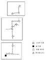
이어서, 스텝 S506에서는 부분 지도마다 세선화된 이동 가능 영역의 분기점(노드) 탐색이 실행된다(도 16 참조). 이어서, 스텝 S508에서는 부분 지도마다 스텝 S506에서 탐색된 분기점의 연결 관계, 및 연결되어 있는 분기점간의 거리를 나타내는 위상 지도가 작성된다(도 17 참조). 이어서, 스텝 S510에서는 스텝 S508에서 작성된 부분 지도마다의 위상 지도가 선택된 연결 포인트에 의해 연결된다(도 18 참조).Subsequently, in step S506, the branch point (node) search of the thinned movable area for each partial map is executed (see FIG. 16). Next, in step S508, the phase map which shows the connection relationship of the branch point searched by step S506 for each partial map, and the distance between the branch points connected is created (refer FIG. 17). Subsequently, in step S510, the phase map for each partial map created in step S508 is connected by the selected connection point (see FIG. 18).
이어지는 스텝 S512에서는 유저로부터 부여된 스타트 지점과 골 지점을 기점으로 해서, 예를 들면 A* 알고리즘을 이용하여 위상 지도 상의 어느 분기점을 통과하면 최소 비용(최단 경로)이 되는지가 구해진다(도 19 참조). 이어서, 스텝 S514에서는 스텝 S512에서 탐색된 최단 경로가 부분 지도마다의 위상 지도로 다시 분할된다(도 20 참조). 그리고, 이어지는 스텝 S516에 있어서 스텝 S514에서 분할된 부분 지도마다 위상 지도에 포함되는 연결 포인트를 연결하는 이동 경로 및 서브 골이 결정되고, 서브 골 점열(좌표열)로 나타내어진 경로 정보가 취득된다(도 21 참조).In a subsequent step S512, starting from the start point and the goal point provided by the user, it is determined which branch point on the phase map is passed by using the A * algorithm, for example, so that the minimum cost (shortest path) is obtained (see Fig. 19). ). Subsequently, in step S514, the shortest path searched in step S512 is further divided into phase maps for each partial map (see Fig. 20). In the following step S516, the movement path and the sub-goal connecting the connection points included in the phase map for each partial map divided in step S514 are determined, and the path information indicated by the sub-goal point sequence (coordinate string) is obtained ( See FIG. 21).
이어서, 도 13에 나타내어지는 자율 이동 처리(반송 모드)의 처리 순서에 대하여 설명한다. 우선, 스텝 S600에서는 자기 위치 추정이 행하여진다. 즉, 인코더(16)로부터 판독된 각 전동 모터(12)의 회전 각도에 따라서 산출된 자기의 이동량을 고려하여 국소 지도와 부분 지도가 대조되고, 그 결과에 의거하여 자기 위치가 추정된다.Next, the process sequence of the autonomous movement process (transfer mode) shown in FIG. 13 is demonstrated. First, in step S600, magnetic position estimation is performed. That is, the local map and the partial map are collated in consideration of the amount of movement of the magnet calculated according to the rotation angle of each
이어서, 스텝 S602에서는 자율 이동 제어가 실행되고, 장해물을 회피하면서 상술한 경로 계획 처리에서 계획된 부분 지도마다의 이동 경로를 따라 자기를 골 지점까지 부분 지도에 걸쳐서 자율 이동시키도록 전동 모터(12)가 제어된다. 상술한 바와 같이, 본 실시형태에서는 장해물을 회피하면서 이동 경로를 따라 자기를 골 지점까지 이동시키는 제어 방법으로서 가상 포텐셜법을 채용했다. 또한, 가상 포텐셜법에 대해서는 상술한 바와 같으므로, 여기에서는 상세한 설명을 생략한다.Subsequently, in step S602, the autonomous movement control is executed, and the
이어지는 스텝 S604에서는 부분 지도의 연결 포인트 근방, 즉 부분 지도의 스위칭 영역에 도달했는지 여부에 대한 판단이 행하여진다. 보다 상세하게는, 자기를 중심으로 하는 소정 반경(예를 들면 구체적으로는 2m이고, 센싱의 유효 범위로부터 결정되는 거리가 바람직하다)의 원과, 연결 포인트를 중심으로 하는 소정 반경(예를 들면 구체적으로는 2m이고, 주행시에 출력되는 최고 속도로부터 역산된 충분히 지도를 스위칭할 수 있는 거리가 바람직하다)의 원이 겹쳐져 있는지 여부에 의해 부분 지도의 스위칭 영역에 도달했는지 여부가 판단된다. 여기에서, 부분 지도의 스위칭 영역에 도달하지 않은 경우(즉 원끼리가 겹쳐져 있지 않은 경우)에는 스텝 S608로 처리가 이행한다. 한편, 부분 지도의 스위칭 영역에 도달하고 있을 때(즉 원끼리가 겹쳐져 있을 때)에는 스텝 S606으로 처리가 이행한다.In subsequent step S604, a determination is made as to whether or not the connection point of the partial map has been reached, that is, whether the switching area of the partial map has been reached. More specifically, a circle of a predetermined radius (e.g., specifically 2 m, preferably a distance determined from the effective range of sensing) centering on the magnetism, and a predetermined radius (e.g., centering the connection point) Specifically, it is determined whether the switching region of the partial map has been reached by whether or not the circle of 2m, which is preferably a distance capable of switching the map sufficiently inverted from the maximum speed output during driving, is overlapped. Here, in the case where the switching area of the partial map is not reached (that is, when the circles do not overlap), the process proceeds to step S608. On the other hand, when the switching region of the partial map is reached (that is, when the circles overlap), the process proceeds to Step S606.
스텝 S606에서는 사용되는 좌표계가 이동 중의 부분 지도의 좌표계로부터 이행처의 부분 지도의 좌표계로, 상술한 좌표 변환 매트릭스[도 10의 식(2) 참조]에 의해 스위칭되는 처리를 수반하여 사용되는 부분 지도의 스위칭이 행하여진다. 그 후, 스텝 S608로 처리가 이행한다. 또한, 원활하게 주행하기 위해서 현재 위치로부터 앞의 복수의 서브 골에 의거하여 축차적으로 설정되는 타깃을 목표로 해서 자율 이동 장치(3)의 이동 제어가 행하여질 경우에는, 연결 포인트 근방의 서브 골 점열을 이동 중의 부분 지도와 이행처의 부분 지도 양쪽에서 갖는 중복 구간이 설정됨과 아울러 주행 중에 연결 포인트 근방에서 경계선이 설정되고, 그 경계선을 자기가 걸쳤을 때에 지도가 스위칭된다.In step S606, the partial map used with the process which switches from the coordinate system of the partial map in movement to the coordinate system of the partial map of a transition destination by the above-mentioned coordinate conversion matrix (refer Formula (2) of FIG. 10) is mentioned. Switching is performed. Thereafter, the process proceeds to step S608. Further, in order to smoothly travel, when the movement control of the autonomous moving
스텝 S608에서는 복수의 부분 지도에 걸쳐서 자기가 골 지점에 도착했는지 여부에 대한 판단이 행하여진다. 여기에서, 자기가 골 지점에 도착하지 않은 경우에는 스텝 S600으로 처리가 이행하고, 골 지점에 도착할 때까지 상술한 스텝 S600~S606의 처리가 반복하여 실행된다. 한편, 자기가 골 지점에 도착했을 때에는 자율 이동 처리(반송 모드)가 종료한다.In step S608, a determination is made as to whether or not he has reached the goal point over the plurality of partial maps. Here, in the case where the self does not reach the goal point, the process shifts to step S600, and the processes of steps S600 to S606 described above are repeatedly executed until the goal point is reached. On the other hand, when the person reaches the goal point, the autonomous movement process (transfer mode) ends.
본 실시형태에 의하면, 독립된 복수의 부분 지도가 작성됨과 아울러 부분 지도 작성시에 연결 포인트가 설정된다. 그리고, 부분 지도끼리를 연결하는 연결 포인트가 선택되고, 연결 포인트간의 연결 관계가 정해진다. 따라서, 이동 환경 전체의 환경 지도를 독립된 부분 지도로 분할함으로써 오차의 누적을 억제할 수 있기 때문에 오차의 누적에 의한 환경 지도의 부정합을 해소할 수 있게 된다. 또한, 각 부분 지도에는 부분 지도에 포함되는 연결 포인트간의 연결 관계가 정해져 있기 때문에 이 연결 관계에 따라서 다른 부분 지도로 옮길 수 있다.According to this embodiment, several independent partial maps are created and a connection point is set at the time of partial map preparation. Then, connection points connecting the partial maps are selected, and the connection relationship between the connection points is determined. Therefore, since the accumulation of errors can be suppressed by dividing the environment map of the entire mobile environment into independent partial maps, it is possible to solve the mismatch of the environment map due to the accumulation of errors. In addition, since the connection relationship between connection points included in the partial map is defined in each partial map, it can be moved to another partial map according to this connection relationship.
또한, 본 실시형태에 의하면 이동 환경 전체의 환경 지도가 부분 지도로 분할되어서 관리되기 때문에, 이동 영역의 부분적인 레이아웃 변경이 있었을 경우에 레이아웃이 변경이 된 부분 지도만을 다시 작성함과 아울러 다시 작성된 부분 지도만을 교체할 수 있다. 따라서, 이동 영역의 부분적인 레이아웃 변경에 유연하게 대응할 수 있게 된다.In addition, according to the present embodiment, since the environmental map of the entire moving environment is divided and managed by partial maps, only partial maps whose layouts have been changed in the case of partial layout change of the moving area are re-created and re-created parts. Only maps can be replaced. Therefore, it is possible to flexibly cope with the partial layout change of the moving area.
본 실시형태에 의하면, 부분 지도마다 세선화된 이동 가능 영역의 분기점(노드)의 연결 관계가 위상 지도로 표현됨과 아울러 부분 지도마다 작성된 위상 지도가 연결됨으로써 이동 영역 전체가 1장의 위상 지도로 표현된다. 여기에서, 위상 지도는 분기점의 연결 관계와 연결되어 있는 분기점간의 거리만을 정보로서 갖는(즉, 좌표의 정보를 갖지 않는) 맵이기 때문에 연결했다고 하여도 계측 오차에 의한 변형의 영향을 받을 일이 없다. 그리고, 연결된 위상 지도를 이용하여 최단 경로 검색이 실행된 후에 다시 위상 지도가 부분 지도마다 분할되고, 검색된 최단 경로에 따라서 이동 경로가 계획된다. 그 결과, 복수의 부분 지도에 걸치는 최단 이동 경로를 계획할 수 있게 된다.According to this embodiment, the connection relationship of the branching point (node) of the thinning movable area | region for every partial map is represented by a phase map, and the phase map created for every partial map is connected, and the whole movement area is represented by one phase map. . Here, since the phase map is a map having only the distance between the branch points connected to the branching point connected as information (that is, it does not have coordinate information), even if it is connected, it is not affected by the deformation due to measurement error. . After the shortest path search is performed by using the connected phase maps, the phase map is further divided for each partial map, and a moving path is planned according to the found shortest path. As a result, it is possible to plan the shortest movement route over the plurality of partial maps.
본 실시형태에 의하면, 복수의 부분 지도에 걸쳐지는 이동 경로를 따라 자율 이동할 때에 이동 중의 부분 지도로부터 다른 부분 지도로 옮길 때에 부분 지도간의 연결 관계에 의거하여 부분 지도가 스위칭된다. 따라서, 복수의 부분 지도에 걸쳐서 목적지(골 지점)까지 자율 이동할 수 있게 된다.According to the present embodiment, the partial map is switched based on the connection relationship between the partial maps when moving from the partial map in movement to another partial map when autonomously moving along the movement paths spanning the plurality of partial maps. Thus, it is possible to autonomously move to a destination (a goal point) over a plurality of partial maps.
본 실시형태에 의하면, 다른 부분 지도로 옮길 때에 이동 중의 부분 지도의 좌표계로부터 이행처의 부분 지도의 좌표계로 좌표계가 스위칭된다. 따라서, 이동 중의 부분 지도로부터 이행처의 부분 지도로 옮길 수 있게 된다.According to this embodiment, when moving to another partial map, a coordinate system is switched from the coordinate system of the partial map in movement to the coordinate system of the partial map of a transition destination. Therefore, it becomes possible to move from the partial map in movement to the partial map of a transition destination.
본 실시형태에서는 이동 경로를 계획할 때에 유저에 의해 설정된 연결 포인트를 그대로 이용했지만, 자율 이동 장치(3)가 설정된 연결 포인트의 위치를 최적화하는 연결 포인트 최적화부(연결 포인트 최적화 수단)를 더 구비하는 구성으로 해도 된다. 이 경우, 상술한 스텝 S504와 스텝 S506 사이에서 다음에 설명하는 연결 포인트 최적화 처리(스텝 S505)가 실행된다. 여기에서, 도 22를 참조하면서 연결 포인트의 최적화 처리에 대하여 설명한다. 또한, 도 22에 있어서 「A」는 유저 입력 등으로 미리 준비된 연결 포인트, 「B」는 최적화된 연결 포인트, 「S」는 스타트 지점, 「G」는 골 지점, 「L1」은 연결 포인트 A를 통과하는 가상의 이동 경로, 「L2」는 최적 이동 경로, 「R1~R8」은 각 맵의 영역선, 「P1~P4」는 중복 영역의 영역선을 나타낸다.In this embodiment, although the connection point set by the user was used as it was when planning a movement route, the autonomous
스텝 S505에서는 다음의 순서를 따라 연결 포인트 B가 구해진다.In step S505, the connection point B is calculated | required in the following procedure.
(1) 부분 지도 2를 부분 지도 1의 좌표계로 변환하고, 부분 지도 1+부분 지도 2의 임시 맵을 준비한다.(1) Convert
(2) 임시 맵 상에서 연결 포인트 A를 통과하는 가상의 이동 경로(L1)를 산출한다.(2) The virtual moving path L1 passing through the connection point A on the temporary map is calculated.
(3) 최적화 방법(공지의 방법, 또는 예를 들면 일본 특허출원 2008-231519에 기재되어 있는 직선화 방법, 평활화 방법)으로 최적 경로(L2)를 결정한다.(3) The optimum path L2 is determined by an optimization method (a known method or a straightening method and smoothing method described in, for example, Japanese Patent Application No. 2008-231519).
(4) 최적 경로(L2) 상에서 부분 지도 1과 부분 지도 2의 중복 영역으로 연결 포인트를 바꿔 놓고, 이것을 연결 포인트(B)라고 한다.(4) The connection point is changed to the overlapping area of the
여기에서, 연결 포인트(B)의 결정 알고리즘에 대해서 보다 상세하게 설명한다. 연결 포인트(B)는 최적 경로(L2)와 영역선(R6)의 교점(Bs)을 스타트, 최적 경로(L2)와 영역선(R4)의 교점(Be)을 엔드로 해서 교점(Bs)~교점(Be) 사이에서 소정 스텝 단위로 이하의 순서를 반복함으로써 결정된다.Here, the determination algorithm of the connection point B is demonstrated in detail. The connection point B starts the intersection point Bs of the optimum path L2 and the area line R6, and makes the end of the intersection point Bs between the optimum path L2 and the area line R4. It is determined by repeating the following procedure in predetermined step units between the intersection points Be.
(5) n회째의 스텝으로서 연결 포인트 후보 B(n)을 통과하고 영역선(R1)에 평행한 직선을 긋고, 이 직선과 각 영역선(R1~R8)의 교점을 구하고, 각 교점과 B(n)을 연결하는 선분의 길이를 구하고, 이들 선분 중 최소의 선분 값을 홀드한다.(5) As the nth step, a straight line passing through the connection point candidate B (n) and parallel to the area line R1 is drawn, and the intersection point of this straight line and each area line R1 to R8 is obtained, and each intersection point and B Obtain the length of the line segment connecting (n), and hold the value of the smallest line segment among these lines.
(6) 영역선(R2~R8)에 대하여 상기 (5)의 처리를 행하고, 8개의 최소값 중에서 가장 작은 값 h(n)을 홀드한다.(6) The above process (5) is performed on the region lines R2 to R8 to hold the smallest value h (n) among the eight minimum values.
(7) n+1회째의 스텝으로 옮겨 다음의 연결 포인트 후보 B(n+1)에 대하여 상기 (5)(6)의 처리를 행하고, 선분의 최소값 h(n+1)을 홀드한다.(7) The process proceeds to (5) (6) above for the next connection point candidate B (n + 1), and holds the minimum value h (n + 1) of the line segment.
(8) h(n)과 h(n+1)을 비교하여 값이 큰 쪽을 h(n+1)로 수정하여 홀드한다.(8) Compare h (n) and h (n + 1), and fix the larger one to h (n + 1) and hold.
(9) 상기 (5)~(8) 처리를 Bs~Be까지 소정 스텝마다 반복함으로써 중복 영역의 영역선(P1~P4)의 각각에 대하여 전체적으로 떨어진 점 B(n)을 산출하고, 이것을 새로운 연결 포인트(B)로 한다. 이상의 처리에 의해, 중복 영역의 각 영역선(P1~P4)의 각각에 대하여 전체적으로 떨어져 있는 최적 경로(L2) 상의 (최적화된)연결 포인트(B)를 구할 수 있다. 또한, 연결 포인트가 치환된 후에는 이 최적화된 연결 포인트를 이용하여 상술한 스텝 S506 이후의 처리가 실행된다.(9) By repeating the processes (5) to (8) for each predetermined step from Bs to Be, the point B (n) which is entirely separated with respect to each of the region lines P1 to P4 in the overlapping region is calculated, and this is connected to a new connection. Let point B be. By the above process, the (optimized) connection point B on the optimum path L2 which is totally separated with respect to each of the area lines P1 to P4 of the overlapping area can be obtained. In addition, after the connection point is replaced, the process after step S506 described above is executed using this optimized connection point.
이상, 본 발명의 실시형태에 대하여 설명했지만, 본 발명은 본 실시형태에 한정되는 것은 아니고 여러 가지 변형이 가능하다. 예를 들면, 본 실시형태에서는 자율 이동 장치(3)를 원격 조작하기 위한 입력 장치로서 조이스틱(21)을 사용했지만, 자율 이동 장치(3)를 유도함과 아울러 연결 포인트를 등록할 수 있으면 되고, 다른 형식의 리모트 콘트롤러 등을 이용해도 된다.As mentioned above, although embodiment of this invention was described, this invention is not limited to this embodiment, A various deformation | transformation is possible. For example, in this embodiment, although the
본 실시형태에서는 유저의 조작에 의거하여 부분 지도의 작성(연결 포인트의 설정, 선택)을 행했지만, 부분 지도의 작성을 자동적으로 행하는 구성으로 할 수도 있다. 예를 들면, 부분 지도를 작성할 때에, 예를 들면 자율 이동 장치의 이동 거리, 부분 지도의 면적, 및/또는 센서 입력(예를 들면 연결 포인트 부근에 설치한 마커를 카메라로 검출했을 경우) 등을 트리거로 해서 자동적으로 다음 신규 부분 지도를 작성하도록 해도 된다. 여기에서, 트리거를 가하기 위한 자율 이동 장치의 이동 거리나 부분 지도의 면적 등의 임계값은 자율 이동 장치의 센서계가 갖는 지도 작성시의 누적 오차의 정도에 따라서 결정할 수 있다. 또한, 자동적으로 다음 신규 부분 지도를 작성할 경우에는 기성 부분 지도에 있어서의 현재의 위치 자세와 신규 부분 지도에 있어서의 원점의 위치 자세를 연결 포인트로서 설정하고, 그 2점을 1세트로 해서 선택하여 지도 스위칭에 사용할 수 있다.In this embodiment, although partial map creation (setting and selection of a connection point) was performed based on a user's operation, it can also be set as the structure which creates a partial map automatically. For example, when creating a partial map, for example, the moving distance of the autonomous mobile device, the area of the partial map, and / or a sensor input (for example, when the camera detects a marker installed near the connection point). The trigger may automatically generate the next new partial map. Here, the threshold value such as the moving distance of the autonomous mobile device for applying the trigger, the area of the partial map, or the like can be determined according to the degree of cumulative error at the time of making the map of the sensor system of the autonomous mobile device. In addition, when automatically creating the next new partial map, the current position posture in the existing partial map and the position posture of the origin in the new partial map are set as connection points, and the two points are selected as one set. Can be used for map switching.
본 실시형태에서는 표시부(25)와 조작 입력부(26)가 일체로 된 터치스크린(24)을 사용했지만, 표시 수단으로서 통상의 디스플레이를 사용함과 아울러 조작 입력 수단으로서 키보드, 마우스 등을 사용하는 구성으로 해도 된다.In this embodiment, although the
본 실시형태에서는 레이저 레인지 파인더(20)를 이용하여 장해물과의 거리를 측정했지만, 레이저 레인지 파인더 대신에 또는 추가하여, 예를 들면 스테레오 카메라, 초음파 센서 등을 사용하는 구성으로 해도 된다.In this embodiment, although the distance with the obstacle was measured using the
본 실시형태에서는 차륜으로서 전방위로 이동 가능한 옴니휠(13)을 채용했지만, 통상의 차륜(조타륜 및 구동륜)을 사용하는 구성으로 해도 된다.In this embodiment, although the
1, 2, 3 : 자율 이동 장치 10 : 본체
12 : 전동 모터 13 : 옴니휠
14 : 휠 15 : 프리롤러
16 : 인코더 20 : 레이저 레인지 파인더
21 : 조이스틱 22 : 레버
23 : 등록 스위치 24 : 터치스크린
25 : 표시부 26 : 조작 입력부
30, 40, 50 : 전자 제어 장치 31 : 국소 지도 작성부
32, 43 : 자기 위치 추정부 33 : 환경 지도 작성부
34, 44, 52 : 기억부 35, 54 : 경로 계획부
36 : 주행 제어부 37 : 센서 정보 취득부
38 : 장해물 회피 제어부 41 : 차분 지도 작성부
42 : 동적 환경 지도 작성부 51 : 부분 지도 작성부
53 : 연결부 55 : 이동 가능 영역 추출부
56 : 위상 지도 작성부 57 : 최단 경로 탐색부
58 : 분할부 59 : 계획부
60 : 스위칭부1, 2, 3: autonomous moving device 10: main body
12: electric motor 13: omni wheel
14: wheel 15: pre-roller
16: encoder 20: laser range finder
21: joystick 22: lever
23: registration switch 24: touch screen
25
30, 40, 50: electronic control device 31: local map preparation unit
32, 43: self position estimation unit 33: environment map preparation unit
34, 44, 52:
36: driving control unit 37: sensor information acquisition unit
38: obstacle avoidance control unit 41: differential map preparation unit
42: dynamic environment mapping unit 51: partial map creation unit
53: connection portion 55: movable area extraction unit
56: phase map preparation unit 57: shortest path search unit
58: division 59: planning
60: switching unit
Claims (7)
Translated fromKorean상기 물체 정보 취득 수단에 의해 취득된 물체의 위치 정보로부터 자기 주변의 국소 지도를 작성하는 국소 지도 작성 수단과,
자기를 이동시키는 이동 수단과,
상기 국소 지도 작성 수단에 의해 작성된 국소 지도, 및 상기 이동 수단의 이동량에 의거하여 자기 위치를 추정하는 자기 위치 추정 수단을 구비하는 자율 이동 장치에 있어서,
유저의 조작에 의거하여 상기 이동 수단을 구동해서 자기를 유도하는 유도 수단,
상기 유도 수단에 의한 유도 중에 상기 자기 위치 추정 수단에 의해 추정된 상기 자기 위치, 및 상기 국소 지도로부터 이동 영역의 환경 지도를 작성하는 환경 지도 작성 수단,
상기 유도 수단에 의한 유도 중에 자기가 소정의 설정 포인트에 위치하고 있을 때의 자기 위치를 상기 설정 포인트의 위치 좌표로서 등록하도록 교시하는 교시 수단,
상기 환경 지도 및 상기 설정 포인트를 기억하는 기억 수단,
상기 기억 수단에 기억되어 있는 상기 환경 지도 상의 상기 설정 포인트를 이용하여 이동 경로를 계획하는 경로 계획 수단,
상기 경로 계획 수단에 의해 계획된 이동 경로를 따라 자율 이동하도록 상기 이동 수단을 제어하는 제어 수단,
상기 이동 경로를 따라 자율 이동할 때에 이동 영역 내의 물체 변화 정도를 나타내는 차분 지도를 작성하는 차분 지도 작성 수단,
상기 이동 경로를 따라 자율 이동할 때에 상기 차분 지도 작성 수단에 의해 작성되는 상기 차분 지도와 상기 환경 지도의 가산 결과에 의거하여 동적 환경 지도를 작성하는 동적 환경 지도 작성 수단을 구비하고,
상기 자기 위치 추정 수단은 상기 이동 경로를 따라 자율 이동할 때에 상기 환경 지도 및 상기 동적 환경 지도 각각과 상기 국소 지도를 대조하고, 그 대조 결과에 의거하여 자기 위치를 추정하며,
상기 차분 지도 작성 수단은 상기 동적 환경 지도와 상기 국소 지도의 가산 결과와 상기 환경 지도의 차분에 의거하여 상기 차분 지도를 갱신하는 것을 특징으로 하는 자율 이동 장치.Object information acquiring means for acquiring position information of an object present around the person;
Local map preparation means for creating a local map around the self from the positional information of the object acquired by the object information acquisition means;
A moving means for moving the magnetism,
In the autonomous moving apparatus comprising a local map created by the local mapping means and a magnetic position estimating means for estimating a magnetic position based on the movement amount of the moving means,
Induction means for inducing magnetism by driving the moving means based on a user's operation;
Environmental map preparation means for creating an environment map of a moving area from the magnetic position estimated by the magnetic position estimation means and the local map during the guidance by the guidance means;
Teaching means for teaching to register the magnetic position when the magnetic body is located at a predetermined set point as the position coordinate of the set point during the induction by the inducing means;
Storage means for storing the environment map and the set point,
Route planning means for planning a movement route using the set point on the environment map stored in the storage means;
Control means for controlling the moving means to autonomously move along the moving path planned by the path planning means,
Difference map making means for creating a difference map indicating a degree of change of an object in a moving area when autonomously moving along the moving path;
And dynamic environment map preparation means for creating a dynamic environment map based on the addition result of the difference map and the environment map created by the difference map preparation means when autonomously moving along the movement path,
The magnetic location estimating means compares each of the environment map and the dynamic environment map with the local map when autonomously moving along the movement path, and estimates the magnetic location based on the matching result,
And the difference mapping means updates the difference map based on a difference between the dynamic environment map, the local map, and the difference between the environment maps.
상기 교시 수단은 상기 설정 포인트의 등록과 아울러 상기 설정 포인트의 속성 정보를 등록하도록 교시하는 것을 특징으로 하는 자율 이동 장치.The method of claim 1,
And the teaching means teaches to register the set point as well as the attribute information of the set point.
Applications Claiming Priority (5)
| Application Number | Priority Date | Filing Date | Title |
|---|---|---|---|
| JPJP-P-2008-256663 | 2008-10-01 | ||
| JP2008256663AJP5298741B2 (en) | 2008-10-01 | 2008-10-01 | Autonomous mobile device |
| JP2008259402AJP5157803B2 (en) | 2008-10-06 | 2008-10-06 | Autonomous mobile device |
| JPJP-P-2008-259402 | 2008-10-06 | ||
| PCT/JP2009/004084WO2010038353A1 (en) | 2008-10-01 | 2009-08-25 | Autonomous movement device |
Related Child Applications (1)
| Application Number | Title | Priority Date | Filing Date |
|---|---|---|---|
| KR1020127023912ADivisionKR101271114B1 (en) | 2008-10-01 | 2009-08-25 | Autonomous movement device |
Publications (2)
| Publication Number | Publication Date |
|---|---|
| KR20110038182A KR20110038182A (en) | 2011-04-13 |
| KR101202695B1true KR101202695B1 (en) | 2012-11-19 |
Family
ID=42073139
Family Applications (2)
| Application Number | Title | Priority Date | Filing Date |
|---|---|---|---|
| KR1020117005480AExpired - Fee RelatedKR101202695B1 (en) | 2008-10-01 | 2009-08-25 | Autonomous movement device |
| KR1020127023912AExpired - Fee RelatedKR101271114B1 (en) | 2008-10-01 | 2009-08-25 | Autonomous movement device |
Family Applications After (1)
| Application Number | Title | Priority Date | Filing Date |
|---|---|---|---|
| KR1020127023912AExpired - Fee RelatedKR101271114B1 (en) | 2008-10-01 | 2009-08-25 | Autonomous movement device |
Country Status (5)
| Country | Link |
|---|---|
| US (2) | US8897917B2 (en) |
| EP (2) | EP2343615B1 (en) |
| KR (2) | KR101202695B1 (en) |
| DK (1) | DK2343615T3 (en) |
| WO (1) | WO2010038353A1 (en) |
Cited By (1)
| Publication number | Priority date | Publication date | Assignee | Title |
|---|---|---|---|---|
| KR101927185B1 (en)* | 2016-10-06 | 2018-12-10 | 현대자동차 주식회사 | Multipurpose Rollable moving device |
Families Citing this family (63)
| Publication number | Priority date | Publication date | Assignee | Title |
|---|---|---|---|---|
| TWI410605B (en)* | 2008-11-28 | 2013-10-01 | Univ Nat Taiwan | Surface inspecting device |
| JP5503419B2 (en)* | 2010-06-03 | 2014-05-28 | 株式会社日立製作所 | Automated guided vehicle and travel control method |
| US8498788B2 (en)* | 2010-10-26 | 2013-07-30 | Deere & Company | Method and system for determining a planned path of a vehicle |
| IT1406207B1 (en)* | 2011-02-21 | 2014-02-14 | Humanware S R L | APTIC ROBOTIC PLANAR DEVICE ON OMNIDIRECTIONAL WHEELS |
| KR101304721B1 (en)* | 2011-07-15 | 2013-09-05 | 주식회사 포스코 | Moving apparatus using the omni-directional wheel |
| TW201305761A (en)* | 2011-07-21 | 2013-02-01 | Ememe Robot Co Ltd | An autonomous robot and a positioning method thereof |
| JP5803392B2 (en)* | 2011-08-01 | 2015-11-04 | 株式会社豊田中央研究所 | Autonomous mobile device |
| JP5601332B2 (en) | 2012-02-08 | 2014-10-08 | 村田機械株式会社 | Transport vehicle |
| US9470658B2 (en)* | 2013-03-12 | 2016-10-18 | The Boeing Company | Self-contained holonomic tracking method and apparatus for non-destructive inspection |
| JP6136435B2 (en)* | 2013-03-25 | 2017-05-31 | 村田機械株式会社 | Autonomous mobile device |
| JP2014191689A (en)* | 2013-03-28 | 2014-10-06 | Hitachi Industrial Equipment Systems Co Ltd | Traveling object attached with position detection device for outputting control command to travel control means of traveling object and position detection device |
| JP6136543B2 (en)* | 2013-05-01 | 2017-05-31 | 村田機械株式会社 | Autonomous mobile |
| US9307368B1 (en)* | 2013-05-14 | 2016-04-05 | Google Inc. | Automatically generating and maintaining a floor plan |
| KR101525071B1 (en)* | 2013-06-12 | 2015-06-02 | 건국대학교 산학협력단 | Device for searching area and mapping for path of intelligent robot in unknown environments |
| KR101427186B1 (en)* | 2013-06-12 | 2014-08-07 | 건국대학교 산학협력단 | Device for searching area and mapping for path of intelligent robot in unknown environments |
| KR101509566B1 (en)* | 2013-06-18 | 2015-04-06 | 박재삼 | Course appointment input apparatus for mobile robot and the method thereof |
| KR102302747B1 (en) | 2013-11-30 | 2021-09-15 | 사우디 아라비안 오일 컴퍼니 | Hinged vehicle chassis |
| EP3754381A1 (en) | 2013-12-10 | 2020-12-23 | SZ DJI Technology Co., Ltd. | Sensor fusion |
| CA2941433C (en)* | 2014-03-12 | 2018-09-04 | The Chugoku Electric Power Co., Inc. | Distance measuring apparatus and distance measuring method |
| JP5819498B1 (en)* | 2014-08-27 | 2015-11-24 | シャープ株式会社 | Autonomous mobile body and autonomous mobile body system |
| JP6539958B2 (en) | 2014-08-28 | 2019-07-10 | 村田機械株式会社 | Carrier |
| FR3025325B1 (en)* | 2014-09-01 | 2016-12-30 | Valeo Schalter & Sensoren Gmbh | DEVICE AND METHOD FOR LOCALIZATION AND MAPPING |
| EP3103043B1 (en) | 2014-09-05 | 2018-08-15 | SZ DJI Technology Co., Ltd. | Multi-sensor environmental mapping |
| WO2016033795A1 (en) | 2014-09-05 | 2016-03-10 | SZ DJI Technology Co., Ltd. | Velocity control for an unmanned aerial vehicle |
| JP6278539B2 (en) | 2014-09-05 | 2018-02-14 | エスゼット ディージェイアイ テクノロジー カンパニー リミテッドSz Dji Technology Co.,Ltd | Flight mode selection based on situation |
| KR101802993B1 (en) | 2015-02-12 | 2017-12-28 | 남한석 | Unlimited movable marking system and marking method thereof |
| JP6762148B2 (en)* | 2015-07-09 | 2020-09-30 | パナソニック インテレクチュアル プロパティ コーポレーション オブ アメリカPanasonic Intellectual Property Corporation of America | Map generation method, mobile robot and map generation system |
| SE539323C2 (en)* | 2015-10-19 | 2017-07-04 | Husqvarna Ab | Improved control of remote demolition robot |
| AU2016210131B2 (en)* | 2016-02-29 | 2017-04-27 | Komatsu Ltd. | Control system for work machine, work machine, and management system for work machine |
| JP6647125B2 (en)* | 2016-04-15 | 2020-02-14 | 株式会社日立産機システム | Position identification system |
| JP6610466B2 (en) | 2016-08-23 | 2019-11-27 | 株式会社デンソー | Vehicle control system |
| US10042362B2 (en) | 2016-11-18 | 2018-08-07 | Waymo Llc | Dynamic routing for autonomous vehicles |
| US11377820B2 (en)* | 2016-12-15 | 2022-07-05 | Deere & Company | Automated work vehicle control system using potential fields |
| JP6809913B2 (en)* | 2017-01-26 | 2021-01-06 | パナソニック株式会社 | Robots, robot control methods, and map generation methods |
| US9921068B2 (en)* | 2017-03-09 | 2018-03-20 | Thomas Danaher Harvey | Devices and methods to facilitate escape from a venue with a sudden hazard |
| EP3605263B1 (en)* | 2017-03-27 | 2022-07-20 | Nidec-Shimpo Corporation | Moving body management system, moving body, traveling management device, and computer program |
| JP6828579B2 (en)* | 2017-04-27 | 2021-02-10 | トヨタ自動車株式会社 | Environmental maintenance robot and its control program |
| US10990829B2 (en)* | 2017-04-28 | 2021-04-27 | Micro Focus Llc | Stitching maps generated using simultaneous localization and mapping |
| JP7000704B2 (en)* | 2017-05-16 | 2022-01-19 | 富士フイルムビジネスイノベーション株式会社 | Mobile service providers and programs |
| KR101853127B1 (en) | 2017-05-19 | 2018-04-27 | 주식회사 랜도르아키텍쳐 | Movable Marking System, Controlling Method For Movable Marking Apparatus and Computer Readable Recording Medium |
| US10451222B2 (en) | 2017-07-12 | 2019-10-22 | Saudi Arabian Oil Company | Magnetic crawler vehicle with passive rear-facing apparatus |
| KR20190051757A (en) | 2017-11-07 | 2019-05-15 | 조준영 | Apparaus with simulation program of mobile robot |
| CN107977003B (en)* | 2017-11-28 | 2020-07-31 | 深圳市杉川机器人有限公司 | Area cleaning method and device |
| CN111356913B (en)* | 2017-12-15 | 2023-08-01 | 株式会社堀场制作所 | Surface property inspection device and recording medium |
| JP6981241B2 (en)* | 2017-12-26 | 2021-12-15 | トヨタ自動車株式会社 | vehicle |
| JP7127303B2 (en)* | 2018-03-09 | 2022-08-30 | カシオ計算機株式会社 | AUTONOMOUS MOBILE DEVICE, AUTONOMOUS MOVEMENT METHOD AND PROGRAM |
| JP7047576B2 (en)* | 2018-04-27 | 2022-04-05 | 株式会社豊田中央研究所 | Cartography device |
| US10835096B2 (en)* | 2018-08-30 | 2020-11-17 | Irobot Corporation | Map based training and interface for mobile robots |
| JP7135690B2 (en)* | 2018-10-04 | 2022-09-13 | ソニーグループ株式会社 | Information processing device and method, program, and mobile body control system |
| US11214967B1 (en) | 2018-11-08 | 2022-01-04 | Scepaniak IP Holdings, LLC | Roof rock spreader |
| US11613041B1 (en) | 2018-11-08 | 2023-03-28 | Scepaniak IP Holdings, LLC | Coping nailer |
| GB2580018A (en)* | 2018-11-10 | 2020-07-15 | Advanced Mech Systems Ltd | Non-destructive testing tool for dual axis position encoding of an inspection probe |
| KR102696487B1 (en) | 2018-12-24 | 2024-08-21 | 삼성전자주식회사 | Method and apparatus for generating local motion based on machine learning |
| EP3936964A4 (en)* | 2019-03-06 | 2022-04-20 | Sony Group Corporation | Map creation device, map creation method, and program |
| CN109960260A (en)* | 2019-03-21 | 2019-07-02 | 上海赛摩物流科技有限公司 | A kind of independently guiding vehicle and its air navigation aid and control device |
| CN110110021A (en)* | 2019-03-22 | 2019-08-09 | 纵目科技(上海)股份有限公司 | Coordinate transformation method, terminal and storage medium between a kind of high-precision local map |
| JP7040673B2 (en)* | 2019-07-08 | 2022-03-23 | 三菱電機株式会社 | Guidance control device and guidance control system for moving objects |
| EP4068035B1 (en)* | 2019-11-25 | 2025-02-12 | Murata Machinery, Ltd. | Autonomous traveling vehicle, control method, and program |
| US12291875B1 (en) | 2019-12-11 | 2025-05-06 | Scepaniak IP Holdings, LLC | Commercial roofing screw machine |
| JP7251467B2 (en)* | 2019-12-25 | 2023-04-04 | トヨタ自動車株式会社 | System and information processing equipment |
| CN114468845B (en)* | 2020-10-23 | 2023-01-20 | 好样科技有限公司 | Self-walking device and control method thereof |
| KR102854324B1 (en)* | 2022-11-15 | 2025-09-03 | 주식회사 벰로보틱스 | A Method for Generating A Characteristic Map of a Driving Robot and A Computer-Readable Recording Medium On Which A Program Performing The Same Is Recorded |
| US12233569B1 (en) | 2023-03-27 | 2025-02-25 | Scepaniak IP Holdings, LLC | Coping nailer |
Citations (1)
| Publication number | Priority date | Publication date | Assignee | Title |
|---|---|---|---|---|
| JP2004280451A (en)* | 2003-03-14 | 2004-10-07 | Matsushita Electric Works Ltd | Autonomous mobile device |
Family Cites Families (35)
| Publication number | Priority date | Publication date | Assignee | Title |
|---|---|---|---|---|
| US4862373A (en)* | 1987-05-13 | 1989-08-29 | Texas Instruments Incorporated | Method for providing a collision free path in a three-dimensional space |
| JPH07129238A (en) | 1993-11-01 | 1995-05-19 | Fujitsu Ltd | Obstacle avoidance route generation method |
| US6321158B1 (en)* | 1994-06-24 | 2001-11-20 | Delorme Publishing Company | Integrated routing/mapping information |
| DE59701408D1 (en)* | 1996-07-02 | 2000-05-11 | Siemens Ag | METHOD FOR CREATING A CELLULAR STRUCTURED ENVIRONMENTAL MAP FROM A SELF-MOBILE MOBILE UNIT ORIENTED IN THE ENVIRONMENT WITH AID WITH WAVE REFLECTION-BASED SENSORS |
| JP3749323B2 (en) | 1996-11-13 | 2006-02-22 | 富士通株式会社 | Mobile device |
| US6845297B2 (en)* | 2000-05-01 | 2005-01-18 | Irobot Corporation | Method and system for remote control of mobile robot |
| US6667592B2 (en)* | 2001-08-13 | 2003-12-23 | Intellibot, L.L.C. | Mapped robot system |
| EP1441632B1 (en)* | 2001-09-26 | 2013-05-01 | F. Robotics Acquisitions Ltd. | Robotic vacuum cleaner |
| GB0126497D0 (en)* | 2001-11-03 | 2002-01-02 | Dyson Ltd | An autonomous machine |
| US6922632B2 (en)* | 2002-08-09 | 2005-07-26 | Intersense, Inc. | Tracking, auto-calibration, and map-building system |
| US7054716B2 (en)* | 2002-09-06 | 2006-05-30 | Royal Appliance Mfg. Co. | Sentry robot system |
| ATE527086T1 (en)* | 2002-12-10 | 2011-10-15 | Honda Motor Co Ltd | CONTROL DEVICE, CONTROL METHOD AND CONTROL PROGRAM FOR A ROBOT |
| US7162338B2 (en)* | 2002-12-17 | 2007-01-09 | Evolution Robotics, Inc. | Systems and methods for computing a relative pose for global localization in a visual simultaneous localization and mapping system |
| GB2404466B (en)* | 2003-07-31 | 2007-07-18 | Hewlett Packard Development Co | Method and apparatus for providing information about a real-world space |
| JP3994950B2 (en)* | 2003-09-19 | 2007-10-24 | ソニー株式会社 | Environment recognition apparatus and method, path planning apparatus and method, and robot apparatus |
| US7689321B2 (en)* | 2004-02-13 | 2010-03-30 | Evolution Robotics, Inc. | Robust sensor fusion for mapping and localization in a simultaneous localization and mapping (SLAM) system |
| EP1741044B1 (en)* | 2004-03-27 | 2011-09-14 | Harvey Koselka | Autonomous personal service robot |
| KR100601960B1 (en)* | 2004-08-05 | 2006-07-14 | 삼성전자주식회사 | How to track and map the robot |
| US20060058921A1 (en)* | 2004-09-13 | 2006-03-16 | Tamao Okamoto | Mobile robot |
| JP2006242978A (en)* | 2005-02-28 | 2006-09-14 | Mitsubishi Heavy Ind Ltd | Moving route map creating method |
| JP4455417B2 (en)* | 2005-06-13 | 2010-04-21 | 株式会社東芝 | Mobile robot, program, and robot control method |
| CN101297267B (en)* | 2005-09-02 | 2012-01-11 | Neato机器人技术公司 | Multi-function robotic device |
| US7912633B1 (en)* | 2005-12-01 | 2011-03-22 | Adept Mobilerobots Llc | Mobile autonomous updating of GIS maps |
| WO2008013568A2 (en)* | 2005-12-30 | 2008-01-31 | Irobot Corporation | Autonomous mobile robot |
| US8577538B2 (en)* | 2006-07-14 | 2013-11-05 | Irobot Corporation | Method and system for controlling a remote vehicle |
| JP4577248B2 (en) | 2006-03-23 | 2010-11-10 | トヨタ自動車株式会社 | Route search system, route search method and route search program for moving body |
| JP2007316966A (en)* | 2006-05-26 | 2007-12-06 | Fujitsu Ltd | Mobile robot, its control method and program |
| JP4984650B2 (en) | 2006-05-30 | 2012-07-25 | トヨタ自動車株式会社 | Mobile device and self-position estimation method of mobile device |
| KR100843085B1 (en)* | 2006-06-20 | 2008-07-02 | 삼성전자주식회사 | Grid map preparation method and device of mobile robot and method and device for area separation |
| US8271132B2 (en)* | 2008-03-13 | 2012-09-18 | Battelle Energy Alliance, Llc | System and method for seamless task-directed autonomy for robots |
| US7587260B2 (en)* | 2006-07-05 | 2009-09-08 | Battelle Energy Alliance, Llc | Autonomous navigation system and method |
| KR100834571B1 (en) | 2006-09-28 | 2008-06-02 | 한국전자통신연구원 | Apparatus and Method for Environment Mapping through Optimal Path of Autonomous Mobile Robot |
| JP2008231519A (en) | 2007-03-22 | 2008-10-02 | Honda Motor Co Ltd | Quasicrystalline particle-dispersed aluminum alloy and method for producing the same |
| JP2009053561A (en)* | 2007-08-28 | 2009-03-12 | Panasonic Electric Works Co Ltd | Map generation system and map generation method for autonomous mobile device |
| KR20090077547A (en)* | 2008-01-11 | 2009-07-15 | 삼성전자주식회사 | Path planning method and device of mobile robot |
- 2009
- 2009-08-25KRKR1020117005480Apatent/KR101202695B1/ennot_activeExpired - Fee Related
- 2009-08-25EPEP09817397.4Apatent/EP2343615B1/enactiveActive
- 2009-08-25KRKR1020127023912Apatent/KR101271114B1/ennot_activeExpired - Fee Related
- 2009-08-25DKDK09817397.4Tpatent/DK2343615T3/enactive
- 2009-08-25USUS13/121,995patent/US8897917B2/enactiveActive
- 2009-08-25WOPCT/JP2009/004084patent/WO2010038353A1/enactiveApplication Filing
- 2009-08-25EPEP18160674.0Apatent/EP3358434A1/ennot_activeWithdrawn
- 2014
- 2014-04-17USUS14/254,978patent/US9244461B2/enactiveActive
Patent Citations (1)
| Publication number | Priority date | Publication date | Assignee | Title |
|---|---|---|---|---|
| JP2004280451A (en)* | 2003-03-14 | 2004-10-07 | Matsushita Electric Works Ltd | Autonomous mobile device |
Cited By (1)
| Publication number | Priority date | Publication date | Assignee | Title |
|---|---|---|---|---|
| KR101927185B1 (en)* | 2016-10-06 | 2018-12-10 | 현대자동차 주식회사 | Multipurpose Rollable moving device |
Also Published As
| Publication number | Publication date |
|---|---|
| KR20110038182A (en) | 2011-04-13 |
| US8897917B2 (en) | 2014-11-25 |
| US20140229053A1 (en) | 2014-08-14 |
| EP2343615B1 (en) | 2018-10-31 |
| WO2010038353A1 (en) | 2010-04-08 |
| US9244461B2 (en) | 2016-01-26 |
| US20110178669A1 (en) | 2011-07-21 |
| EP2343615A1 (en) | 2011-07-13 |
| EP3358434A1 (en) | 2018-08-08 |
| EP2343615A4 (en) | 2015-07-29 |
| KR20120118070A (en) | 2012-10-25 |
| DK2343615T3 (en) | 2019-02-18 |
| KR101271114B1 (en) | 2013-06-04 |
Similar Documents
| Publication | Publication Date | Title |
|---|---|---|
| KR101202695B1 (en) | Autonomous movement device | |
| JP5157803B2 (en) | Autonomous mobile device | |
| JP5298741B2 (en) | Autonomous mobile device | |
| US11785430B2 (en) | System and method for real-time indoor navigation | |
| JP5927735B2 (en) | Map data creation device, autonomous mobile system and autonomous mobile control device | |
| Li et al. | Collaborative mapping and autonomous parking for multi-story parking garage | |
| US9020301B2 (en) | Method and system for three dimensional mapping of an environment | |
| JP5016399B2 (en) | Map information creation device and autonomous mobile device equipped with the map information creation device | |
| Kusuma et al. | Humanoid robot path planning and rerouting using A-Star search algorithm | |
| CN111149072A (en) | Magnetometer for robot navigation | |
| JP2007316966A (en) | Mobile robot, its control method and program | |
| KR20170088228A (en) | Map building system and its method based on multi-robot localization | |
| WO2016013095A1 (en) | Autonomous moving device | |
| KR20180135755A (en) | Method of configuring position based on vision information and robot implementing thereof | |
| Hasegawa et al. | Experimental verification of path planning with SLAM | |
| Gonzalez et al. | A mobile robot iconic position estimator using a radial laser scanner | |
| CN107632607A (en) | Mobile robot accurate positioning method based on two-dimensional laser Slam and Tag label | |
| Cho et al. | Map based indoor robot navigation and localization using laser range finder | |
| JP2006234453A (en) | Method of registering landmark position for self-position orientation | |
| Zeghmi et al. | A Kalman-particle hybrid filter for improved localization of AGV in indoor environment | |
| Shioya et al. | Minimal Autonomous Mover-MG-11 for Tsukuba Challenge– | |
| Garcia et al. | Positioning and localization system for autonomous wheelchairs | |
| CN113932814A (en) | Multi-mode map-based co-location method | |
| Jensfelt et al. | A mobile robot system for automatic floor marking | |
| JP3009372B2 (en) | Driving control method for autonomous vehicles |
Legal Events
| Date | Code | Title | Description |
|---|---|---|---|
| A201 | Request for examination | ||
| PA0105 | International application | St.27 status event code:A-0-1-A10-A15-nap-PA0105 | |
| PA0201 | Request for examination | St.27 status event code:A-1-2-D10-D11-exm-PA0201 | |
| PG1501 | Laying open of application | St.27 status event code:A-1-1-Q10-Q12-nap-PG1501 | |
| E902 | Notification of reason for refusal | ||
| PE0902 | Notice of grounds for rejection | St.27 status event code:A-1-2-D10-D21-exm-PE0902 | |
| A107 | Divisional application of patent | ||
| E13-X000 | Pre-grant limitation requested | St.27 status event code:A-2-3-E10-E13-lim-X000 | |
| P11-X000 | Amendment of application requested | St.27 status event code:A-2-2-P10-P11-nap-X000 | |
| P13-X000 | Application amended | St.27 status event code:A-2-2-P10-P13-nap-X000 | |
| PA0104 | Divisional application for international application | St.27 status event code:A-0-1-A10-A18-div-PA0104 St.27 status event code:A-0-1-A10-A16-div-PA0104 | |
| E701 | Decision to grant or registration of patent right | ||
| PE0701 | Decision of registration | St.27 status event code:A-1-2-D10-D22-exm-PE0701 | |
| GRNT | Written decision to grant | ||
| PR0701 | Registration of establishment | St.27 status event code:A-2-4-F10-F11-exm-PR0701 | |
| PR1002 | Payment of registration fee | St.27 status event code:A-2-2-U10-U12-oth-PR1002 Fee payment year number:1 | |
| PG1601 | Publication of registration | St.27 status event code:A-4-4-Q10-Q13-nap-PG1601 | |
| R18-X000 | Changes to party contact information recorded | St.27 status event code:A-5-5-R10-R18-oth-X000 | |
| FPAY | Annual fee payment | Payment date:20151106 Year of fee payment:4 | |
| PR1001 | Payment of annual fee | St.27 status event code:A-4-4-U10-U11-oth-PR1001 Fee payment year number:4 | |
| FPAY | Annual fee payment | Payment date:20161104 Year of fee payment:5 | |
| PR1001 | Payment of annual fee | St.27 status event code:A-4-4-U10-U11-oth-PR1001 Fee payment year number:5 | |
| FPAY | Annual fee payment | Payment date:20171103 Year of fee payment:6 | |
| PR1001 | Payment of annual fee | St.27 status event code:A-4-4-U10-U11-oth-PR1001 Fee payment year number:6 | |
| PR1001 | Payment of annual fee | St.27 status event code:A-4-4-U10-U11-oth-PR1001 Fee payment year number:7 | |
| PR1001 | Payment of annual fee | St.27 status event code:A-4-4-U10-U11-oth-PR1001 Fee payment year number:8 | |
| PC1903 | Unpaid annual fee | St.27 status event code:A-4-4-U10-U13-oth-PC1903 Not in force date:20201114 Payment event data comment text:Termination Category : DEFAULT_OF_REGISTRATION_FEE | |
| PC1903 | Unpaid annual fee | St.27 status event code:N-4-6-H10-H13-oth-PC1903 Ip right cessation event data comment text:Termination Category : DEFAULT_OF_REGISTRATION_FEE Not in force date:20201114 | |
| P22-X000 | Classification modified | St.27 status event code:A-4-4-P10-P22-nap-X000 | |
| P22-X000 | Classification modified | St.27 status event code:A-4-4-P10-P22-nap-X000 |