KR101202163B1 - Audio encoder and decoder - Google Patents
Audio encoder and decoderDownload PDFInfo
- Publication number
- KR101202163B1 KR101202163B1KR1020107017305AKR20107017305AKR101202163B1KR 101202163 B1KR101202163 B1KR 101202163B1KR 1020107017305 AKR1020107017305 AKR 1020107017305AKR 20107017305 AKR20107017305 AKR 20107017305AKR 101202163 B1KR101202163 B1KR 101202163B1
- Authority
- KR
- South Korea
- Prior art keywords
- signal
- unit
- transform
- frame
- long term
- Prior art date
- Legal status (The legal status is an assumption and is not a legal conclusion. Google has not performed a legal analysis and makes no representation as to the accuracy of the status listed.)
- Active
Links
- 238000013139quantizationMethods0.000claimsabstractdescription89
- 230000007774longtermEffects0.000claimsabstractdescription78
- 238000001914filtrationMethods0.000claimsabstractdescription26
- 230000003044adaptive effectEffects0.000claimsabstractdescription17
- 238000006243chemical reactionMethods0.000claimsabstractdescription11
- 238000000034methodMethods0.000claimsdescription71
- 230000003595spectral effectEffects0.000claimsdescription38
- 239000000872bufferSubstances0.000claimsdescription34
- 238000004458analytical methodMethods0.000claimsdescription29
- 230000015572biosynthetic processEffects0.000claimsdescription18
- 238000003786synthesis reactionMethods0.000claimsdescription17
- 230000005236sound signalEffects0.000claimsdescription16
- 239000013598vectorSubstances0.000claimsdescription12
- 230000011664signalingEffects0.000claimsdescription7
- 230000010076replicationEffects0.000claimsdescription5
- 238000005192partitionMethods0.000claimsdescription4
- 230000001131transforming effectEffects0.000claimsdescription4
- 238000012952ResamplingMethods0.000claimsdescription3
- 230000002194synthesizing effectEffects0.000claims1
- 230000006870functionEffects0.000description25
- 238000001228spectrumMethods0.000description19
- 230000000875corresponding effectEffects0.000description17
- 238000000605extractionMethods0.000description17
- 230000000873masking effectEffects0.000description16
- 238000004422calculation algorithmMethods0.000description12
- 230000008901benefitEffects0.000description8
- 238000013507mappingMethods0.000description8
- 238000005070samplingMethods0.000description8
- 230000008859changeEffects0.000description7
- 230000000694effectsEffects0.000description7
- 230000008569processEffects0.000description7
- 238000000746purificationMethods0.000description6
- 238000007493shaping processMethods0.000description6
- 238000005259measurementMethods0.000description5
- 230000004048modificationEffects0.000description5
- 238000012986modificationMethods0.000description5
- 238000010606normalizationMethods0.000description5
- 238000012546transferMethods0.000description5
- 230000009466transformationEffects0.000description5
- 238000012804iterative processMethods0.000description4
- 230000007704transitionEffects0.000description4
- 230000007246mechanismEffects0.000description3
- 238000012545processingMethods0.000description3
- 230000009471actionEffects0.000description2
- 238000013459approachMethods0.000description2
- 230000009286beneficial effectEffects0.000description2
- 230000005540biological transmissionEffects0.000description2
- 238000004590computer programMethods0.000description2
- 230000001143conditioned effectEffects0.000description2
- 238000007796conventional methodMethods0.000description2
- 230000001419dependent effectEffects0.000description2
- 238000001514detection methodMethods0.000description2
- 230000014509gene expressionEffects0.000description2
- 230000000737periodic effectEffects0.000description2
- 230000009467reductionEffects0.000description2
- 230000000630rising effectEffects0.000description2
- 230000011218segmentationEffects0.000description2
- 230000002123temporal effectEffects0.000description2
- 238000011144upstream manufacturingMethods0.000description2
- 101000972854Lens culinaris Non-specific lipid-transfer protein 3Proteins0.000description1
- 101710196809Non-specific lipid-transfer protein 1Proteins0.000description1
- 101710196810Non-specific lipid-transfer protein 2Proteins0.000description1
- 238000004364calculation methodMethods0.000description1
- 230000000295complement effectEffects0.000description1
- 230000006835compressionEffects0.000description1
- 238000007906compressionMethods0.000description1
- 230000001276controlling effectEffects0.000description1
- 238000012937correctionMethods0.000description1
- 230000002596correlated effectEffects0.000description1
- 230000007423decreaseEffects0.000description1
- 230000009977dual effectEffects0.000description1
- 238000004134energy conservationMethods0.000description1
- 238000005516engineering processMethods0.000description1
- 239000000284extractSubstances0.000description1
- 238000011049fillingMethods0.000description1
- 238000005187foamingMethods0.000description1
- 230000006872improvementEffects0.000description1
- 230000001939inductive effectEffects0.000description1
- 230000010354integrationEffects0.000description1
- 238000002156mixingMethods0.000description1
- 239000000203mixtureSubstances0.000description1
- 238000005457optimizationMethods0.000description1
- 230000001172regenerating effectEffects0.000description1
- 230000008929regenerationEffects0.000description1
- 238000011069regeneration methodMethods0.000description1
- 230000004044responseEffects0.000description1
- 238000013179statistical modelMethods0.000description1
- 238000012360testing methodMethods0.000description1
- 238000000844transformationMethods0.000description1
- 230000001052transient effectEffects0.000description1
- 230000002087whitening effectEffects0.000description1
Images


Classifications
- G—PHYSICS
- G10—MUSICAL INSTRUMENTS; ACOUSTICS
- G10L—SPEECH ANALYSIS TECHNIQUES OR SPEECH SYNTHESIS; SPEECH RECOGNITION; SPEECH OR VOICE PROCESSING TECHNIQUES; SPEECH OR AUDIO CODING OR DECODING
- G10L19/00—Speech or audio signals analysis-synthesis techniques for redundancy reduction, e.g. in vocoders; Coding or decoding of speech or audio signals, using source filter models or psychoacoustic analysis
- G10L19/02—Speech or audio signals analysis-synthesis techniques for redundancy reduction, e.g. in vocoders; Coding or decoding of speech or audio signals, using source filter models or psychoacoustic analysis using spectral analysis, e.g. transform vocoders or subband vocoders
- G10L19/032—Quantisation or dequantisation of spectral components
- G—PHYSICS
- G10—MUSICAL INSTRUMENTS; ACOUSTICS
- G10L—SPEECH ANALYSIS TECHNIQUES OR SPEECH SYNTHESIS; SPEECH RECOGNITION; SPEECH OR VOICE PROCESSING TECHNIQUES; SPEECH OR AUDIO CODING OR DECODING
- G10L19/00—Speech or audio signals analysis-synthesis techniques for redundancy reduction, e.g. in vocoders; Coding or decoding of speech or audio signals, using source filter models or psychoacoustic analysis
- G10L19/04—Speech or audio signals analysis-synthesis techniques for redundancy reduction, e.g. in vocoders; Coding or decoding of speech or audio signals, using source filter models or psychoacoustic analysis using predictive techniques
- G10L19/26—Pre-filtering or post-filtering
- G—PHYSICS
- G10—MUSICAL INSTRUMENTS; ACOUSTICS
- G10L—SPEECH ANALYSIS TECHNIQUES OR SPEECH SYNTHESIS; SPEECH RECOGNITION; SPEECH OR VOICE PROCESSING TECHNIQUES; SPEECH OR AUDIO CODING OR DECODING
- G10L19/00—Speech or audio signals analysis-synthesis techniques for redundancy reduction, e.g. in vocoders; Coding or decoding of speech or audio signals, using source filter models or psychoacoustic analysis
- G10L19/008—Multichannel audio signal coding or decoding using interchannel correlation to reduce redundancy, e.g. joint-stereo, intensity-coding or matrixing
- G—PHYSICS
- G10—MUSICAL INSTRUMENTS; ACOUSTICS
- G10L—SPEECH ANALYSIS TECHNIQUES OR SPEECH SYNTHESIS; SPEECH RECOGNITION; SPEECH OR VOICE PROCESSING TECHNIQUES; SPEECH OR AUDIO CODING OR DECODING
- G10L19/00—Speech or audio signals analysis-synthesis techniques for redundancy reduction, e.g. in vocoders; Coding or decoding of speech or audio signals, using source filter models or psychoacoustic analysis
- G10L19/02—Speech or audio signals analysis-synthesis techniques for redundancy reduction, e.g. in vocoders; Coding or decoding of speech or audio signals, using source filter models or psychoacoustic analysis using spectral analysis, e.g. transform vocoders or subband vocoders
- G10L19/0212—Speech or audio signals analysis-synthesis techniques for redundancy reduction, e.g. in vocoders; Coding or decoding of speech or audio signals, using source filter models or psychoacoustic analysis using spectral analysis, e.g. transform vocoders or subband vocoders using orthogonal transformation
- G—PHYSICS
- G10—MUSICAL INSTRUMENTS; ACOUSTICS
- G10L—SPEECH ANALYSIS TECHNIQUES OR SPEECH SYNTHESIS; SPEECH RECOGNITION; SPEECH OR VOICE PROCESSING TECHNIQUES; SPEECH OR AUDIO CODING OR DECODING
- G10L19/00—Speech or audio signals analysis-synthesis techniques for redundancy reduction, e.g. in vocoders; Coding or decoding of speech or audio signals, using source filter models or psychoacoustic analysis
- G10L19/02—Speech or audio signals analysis-synthesis techniques for redundancy reduction, e.g. in vocoders; Coding or decoding of speech or audio signals, using source filter models or psychoacoustic analysis using spectral analysis, e.g. transform vocoders or subband vocoders
- G10L19/032—Quantisation or dequantisation of spectral components
- G10L19/035—Scalar quantisation
Landscapes
- Engineering & Computer Science (AREA)
- Physics & Mathematics (AREA)
- Spectroscopy & Molecular Physics (AREA)
- Acoustics & Sound (AREA)
- Signal Processing (AREA)
- Health & Medical Sciences (AREA)
- Audiology, Speech & Language Pathology (AREA)
- Human Computer Interaction (AREA)
- Computational Linguistics (AREA)
- Multimedia (AREA)
- Mathematical Physics (AREA)
- Compression, Expansion, Code Conversion, And Decoders (AREA)
- Reduction Or Emphasis Of Bandwidth Of Signals (AREA)
- Stereo-Broadcasting Methods (AREA)
- Analogue/Digital Conversion (AREA)
- Compression Or Coding Systems Of Tv Signals (AREA)
Abstract
Translated fromKoreanDescription
Translated fromKorean본 발명은 오디오 신호의 코딩에 관한 것으로, 특히 음성(speech), 음악 또는 이들의 혼합에 국한되지 않은 어떤 오디오 신호의 코딩에 관한 것이다.The present invention relates to the coding of audio signals, and more particularly to the coding of certain audio signals, not limited to speech, music or a mixture thereof.
종래기술에는 코딩을 신호의 소스 모델, 예를 들어 인간 발성 시스템을 기본으로 함으로써 음성 신호를 코딩하도록 특별히 설계된 음성 코더가 있다. 이러한 코더들은 음악 또는 어떤 다른 비-음성(non-speech) 신호와 같은 임의의 오디오 신호들을 처리하지 못한다. 추가적으로, 종래기술에는 신호의 소스 모델에 대한 것이 아니라 인간 청각 시스템에 대한 가정을 코딩의 기반으로 하는, 통상적으로 오디오 코더들로 일컬어지는 음악-코더들이 있다. 이러한 오디오 코더들은, 비록 음성 신호에 대해 낮은 비트레이트에서, 임의의 신호들을 매우 잘 처리할 수 있지만, 전용 음성 코더들이 보다 더 우월한 오디오 품질을 보인다. 따라서, 지금까지는, 낮은 비트 레이트에서 동작할 때 음악을 위한 음악 코더뿐 아니라 음성을 위한 음성 코더 또한 잘 수행하는, 임의의 오디오 신호들의 코딩을 위한 일반적인 코딩 구조는 존재하지 않는다.Prior art has a speech coder specifically designed to code a speech signal by coding based on a source model of the signal, eg a human speech system. These coders do not process any audio signals, such as music or any other non-speech signal. Additionally, the prior art has music-coders, commonly referred to as audio coders, that are based on coding assumptions about the human auditory system and not on the source model of the signal. These audio coders, although at low bitrates for voice signals, can handle arbitrary signals very well, dedicated voice coders show superior audio quality. Thus, to date, there is no general coding scheme for coding of any audio signals that, when operating at low bit rates, performs well not only music coder for music but also voice coder for voice.
따라서, 향상된 오디오 품질 및/또는 감소된 비트 레이트를 가지는 개선된 오디오 인코더 및 디코더에 대한 필요가 있다.Thus, there is a need for an improved audio encoder and decoder with improved audio quality and / or reduced bit rate.
본 발명은 특정 신호에 특별히 맞춰진 시스템의 품질과 동등하거나 그보다 나은 품질 레벨에서 임의의 오디오 신호들을 효과적으로 코딩하는 것과 관련된다.The present invention relates to the efficient coding of any audio signals at a quality level equal to or better than the quality of a system specifically tailored to a particular signal.
본 발명은 선형 예측 코딩(LPC) 및 LPC 처리된 신호 상에서 동작하는 변환 코더 파트 양쪽을 포함하는 오디오 코덱 알고리즘을 지향한다.The present invention is directed to an audio codec algorithm that includes both linear predictive coding (LPC) and transform coder parts operating on LPC processed signals.
본 발명은 또한 가변 프레임 크기를 가지는 오디오 인코더에서 비트 저장소(bit reservoir)를 효과적으로 사용하는 것에 관련된다.The present invention also relates to the effective use of bit reservoirs in audio encoders having variable frame sizes.
본 발명은 가변 프레임 크기를 갖는 변환 코더와의 조합에서 장기 예측(long term prediction)의 작용에 또한 관련된다.The present invention also relates to the action of long term prediction in combination with a transform coder having a variable frame size.
본 발명은 또한 오디오 신호를 인코딩하고 비트스트림을 생성하는 인코더, 및 비트스트림을 디코딩하고 입력 오디오 신호와는 지각적으로(perceptually) 구분되지 않는 재구성된 오디오 신호를 생성하는 디코더에 관련된다.The invention also relates to an encoder for encoding an audio signal and generating a bitstream, and a decoder for decoding a bitstream and generating a reconstructed audio signal which is not perceptually distinct from an input audio signal.
본 발명은 변환 코더에 기반한 오디오 코딩 시스템을 제공하며, 음성 코더로부터 기본적인 예측 및 형상화 모듈들을 포함한다. 본 발명의 시스템은 적응적 필터에 기반하여 입력 신호를 필터링하는 선형 예측 유닛; 상기 필터링된 입력 신호의 프레임을 변환 영역으로 변환하는 변환 유닛; 변환 영역 신호를 양자화하는 양자화 유닛; 상기 필터링된 입력 신호의 이전 세그먼트의 재구성물에 기초하여 상기 필터링된 입력 신호의 상기 프레임의 추산물을 결정하는 장기 예측 유닛; 및 상기 양자화 유닛으로의 입력인 상기 변환 영역 신호를 발생하기 위해 상기 변환 영역에서 상기 장기 예측 추산물과 상기 변환된 입력 신호를 결합하는 변환 영역 신호 결합 유닛을 포함한다.The present invention provides an audio coding system based on a transform coder and includes basic prediction and shaping modules from a speech coder. The system of the present invention comprises a linear prediction unit for filtering an input signal based on an adaptive filter; A conversion unit for converting the frame of the filtered input signal into a conversion region; A quantization unit for quantizing the transform region signal; A long term prediction unit for determining an estimate of the frame of the filtered input signal based on a reconstruction of a previous segment of the filtered input signal; And a transform region signal combining unit for combining the long term prediction estimate with the transformed input signal in the transform region to generate the transform region signal that is an input to the quantization unit.
오디오 코딩 시스템은 상기 필터링된 신호의 상기 프레임의 시간 영역 재구성물을 발생시키는 역양자화 및 역변환 유닛을 더 포함할 수 있다. 또한, 상기 필터링된 입력 신호의 이전 프레임들의 시간 영역 재구성물들을 저장하는 장기 예측 버퍼가 제공될 수 있다. 이들 유닛들은 양자화 유닛으로부터 장기 예측 추출 유닛으로의 피드백 루프로 정렬될 수 있으며, 장기 예측 추출 유닛은 필터링된 입력 신호의 현재 프레임과 가장 잘 매치하는 재구성된 세그먼트를 장기 예측 버퍼에서, 찾는다. 또한, 상기 장기 예측 버퍼로부터 현재의 프레임과 가장 잘 매치하도록 선택된 세그먼트의 이득을 조정하는, 장기 예측 이득 추산 유닛이 제공될 수 있다. 바람직하게, 장기 예측 추산물은 변환 영역에서 변환된 입력 신호로부터 감산된다. 그러므로, 상기 선택된 세그먼트를 상기 변환 영역으로 변환하는 제2 변환 유닛이 제공될 수 있다. 장기 예측 루프는 또한 역 양자화 후에 시간 영역으로의 역 변환 이전에 변환 영역에서의 상기 장기 예측 추산물을 피드백 신호에 가산하는 것을 포함한다. 따라서, 변환 영역에서 이전 프레임들에 기초하여 상기 필터링된 입력 신호의 현 프레임을 예측하는, 후방 적응적 장기 예측 방법이 사용될 수 있다. 더 효과적이기 위해, 상기 장기 예측 방법은 일부 예들에 대해 이하 설명되는 바와 같이, 다양한 방식으로 더 적합하게 될 수 있다.The audio coding system may further comprise an inverse quantization and inverse transform unit for generating a time domain reconstruction of the frame of the filtered signal. In addition, a long term prediction buffer may be provided that stores time domain reconstructions of previous frames of the filtered input signal. These units can be arranged in a feedback loop from the quantization unit to the long term prediction extraction unit, which looks for, in the long term prediction buffer, the reconstructed segment that best matches the current frame of the filtered input signal. In addition, a long term prediction gain estimating unit may be provided that adjusts the gain of the selected segment to best match the current frame from the long term prediction buffer. Preferably, the long term prediction estimate is subtracted from the transformed input signal in the transform domain. Therefore, a second transform unit for converting the selected segment into the transform region can be provided. The long term prediction loop also includes adding the long term prediction estimate in the transform domain to the feedback signal after inverse quantization and before inverse transform into the time domain. Thus, a backward adaptive long term prediction method can be used that predicts the current frame of the filtered input signal based on previous frames in the transform domain. To be more effective, the long term prediction method can be more suitable in various ways, as described below for some examples.
입력 신호를 필터링하는 적응적 필터는 바람직하게, 백색화된 입력 신호를 생성하는 LPC 필터를 포함하는, 선형 예측 코딩(LPC) 분석에 기반한다. 입력 데이터의 현 프레임을 위한 LPC 파라미터들은 종래에 공지된 알고리즘에 의해 결정될 수 있다. LPC 파라미터 추산 유닛은, 입력 데이터의 프레임을 위해, 다항식, 전달 함수, 반사 계수, 라인 스펙트럼 주파수 등과 같은 어떠한 적절한 LPC 파라미터 표현도 계산할 수 있다. 코딩 또는 다른 프로세싱을 위해 사용된 특정 타입의 LPC 파라미터 표현은 각각의 요구사항에 좌우된다. 당업자에게 공지된 바와 같이, 일부 표현들이 어떤 동작에 대해 다른 것들보다 더 적합하며, 그에 따라 이들 동작들을 수행하는데 바람직하다. 선형 예측 유닛은 고정된, 예컨대, 20 msec의 제1 프레임 길이 상에서 동작할 수 있다. 선형 예측 필터링은 저주파수와 같은 어떤 주파수 범위를 다른 주파수들보다 선택적으로 강조하기 위해 워핑된 주파수축에 대해 추가로 동작할 수 있다.The adaptive filter for filtering the input signal is preferably based on linear prediction coding (LPC) analysis, which includes an LPC filter for producing a whitened input signal. LPC parameters for the current frame of input data may be determined by a conventionally known algorithm. The LPC parameter estimation unit may calculate any suitable LPC parameter representation, such as polynomials, transfer functions, reflection coefficients, line spectral frequencies, etc., for the frame of input data. The particular type of LPC parameter representation used for coding or other processing depends on the respective requirements. As is known to those skilled in the art, some representations are more suitable for some operations than others, and are therefore preferred for performing these operations. The linear prediction unit may operate on a first frame length of fixed, eg, 20 msec. Linear predictive filtering may further operate on the warped frequency axis to selectively emphasize certain frequency ranges, such as low frequencies, over other frequencies.
필터링된 입력 신호의 프레임에 적용되는 변환은 바람직하게, 가변의 제2 프레임 길이 상에서 동작하는 변경 이산 코싸인 변환(MDCT)이다. 오디오 코딩 시스템은 코딩 비용 함수를 최소화함으로써 MDCT 윈도우들을 오버랩핑하는 상기 제2 프레임 길이를 상기 입력 신호 블록에 대해 결정하는데, 바람직하게는, 몇 개의 프레임들을 포함하는 전체 입력 신호의 블록에 대해, 간단한 지각적 엔트로피를 결정하는 윈도우 시퀀스 제어 유닛을 포함할 수 있다. 따라서, 입력 신호 블록의 각 제2 프레임 길이들을 갖는 MDCT 윈도우들로의 최적의 세그먼트화가 도출된다. 그 결과, LPC를 제외한 모든 프로세싱을 위한 하나의 기본 유닛으로서, 적응적 길이 MDCT 프레임을 갖는 음성 코더 엘리먼트를 포함하는 변환 영역 코딩 구조가 제안된다. MDCT 프레임 길이들이 많은 다른 값들에 대해 취해지기 때문에, 최적의 시퀀스가 발견될 수 있으며, 작은 윈도우 크기와 큰 윈도우 크기만이 적용되는 종래 기술에서 일반적인, 급격한 프레임 크기 변화가 회피될 수 있다. 추가적으로, 작은 윈도우 크기와 큰 윈도우 크기 사이의 전이를 위해 일부 종래 방법들에 사용되는 샤프한 에지들을 갖는 전이(transitional) 변환 윈도우가 필요하지 않다.The transform applied to the frame of the filtered input signal is preferably a modified discrete cosine transform (MDCT) operating on a variable second frame length. An audio coding system determines for the input signal block the second frame length that overlaps MDCT windows by minimizing a coding cost function, preferably for a block of the entire input signal comprising several frames, It may include a window sequence control unit for determining the perceptual entropy. Thus, optimal segmentation into MDCT windows with respective second frame lengths of the input signal block is derived. As a result, as one basic unit for all processing except LPC, a transform domain coding structure including a speech coder element with an adaptive length MDCT frame is proposed. Since MDCT frame lengths are taken for many different values, an optimal sequence can be found, and the abrupt frame size change, which is common in the prior art, where only small and large window sizes are applied, can be avoided. In addition, there is no need for a transitional transform window with sharp edges used in some conventional methods for the transition between small and large window sizes.
바람직하게, 연속적인 MDCT 윈도우 길이들은 최대 2의 인자만큼 변화하며 및/또는 MDCT 윈도우 길이들은 다이애딕 값들이다. 구체적으로, MDCT 윈도우 길이들은 입력 신호 블록의 다이애딕 파티션들일 수 있다. 그러므로, MDCT 윈도우 시퀀스는 적은 개수의 비트들로 인코딩하는 것이 용이한 미리 결정된 시퀀스에 한정된다. 추가적으로, 윈도우 시퀀스는 프레임 크기의 완만한 전이를 가지며, 그에 따라 급격한 프레임 크기 변화는 없다.Preferably, successive MDCT window lengths vary by a factor of up to 2 and / or MDCT window lengths are diadic values. Specifically, the MDCT window lengths may be diadic partitions of the input signal block. Therefore, the MDCT window sequence is limited to a predetermined sequence that is easy to encode into a small number of bits. In addition, the window sequence has a gentle transition of frame size, so there is no sudden frame size change.
MDCT 윈도우 길이와 윈도우 시퀀스의 윈도우 형상을 함께 인코딩하는 윈도우 시퀀스 인코더가 제공될 수 있다. 통합 인코딩은 중복성을 제거할 수 있으며 더 적은 비트들을 요구한다. 윈도우 시퀀스 인코더는 윈도우 길이 및 윈도우 시퀀스의 형상을 인코딩할 때 디코더에서 재구성될 수 있는 불필요한 정보(비트들)를 생략하도록 윈도우 크기 제약조건들을 고려할 수 있다.A window sequence encoder may be provided that encodes the MDCT window length and the window shape of the window sequence together. Integrated encoding can eliminate redundancy and requires fewer bits. The window sequence encoder may consider window size constraints to omit unnecessary information (bits) that may be reconstructed at the decoder when encoding the window length and the shape of the window sequence.
윈도우 시퀀스 제어 유닛은 입력 신호 블록을 위한 코딩 비용 함수를 최소화하는 MDCT 윈도우 길이들의 시퀀스를 검색할 때 윈도우 길이 후보들을 위해, 장기 예측 유닛에 의해 생성된 장기 예측 추산물들을 고려하도록 추가로 구성될 수 있다. 이 실시예에서, 인코딩을 위해 적용된 MDCT 윈도우들의 개선된 시퀀스를 초래하는 장기 예측 루프는 MDCT 윈도우 길이들을 결정할 때 폐쇄된다. 또한, 시간-워핑 커브에 따라 상기 필터링된 입력 신호를 재샘플링함으로써 상기 필터링된 신호의 프레임에서 피치 성분을 균일하게 정렬시키는 시간 워핑 유닛이 제공될 수 있다. 시간-워프(time-warp) 커브는 바람직하게, 프레임에서 피치 성분들을 균일하게 정렬하도록 결정된다. 따라서, 변환 유닛 및/또는 장기 예측 유닛은 일정한 피치를 갖는 시간-워핑된 신호 상에서 동작할 수 있는데, 이는 신호 분석의 정확도를 향상시킨다.The window sequence control unit may be further configured to consider, for window length candidates, long term prediction estimates generated by the long term prediction unit when retrieving a sequence of MDCT window lengths that minimize a coding cost function for the input signal block. have. In this embodiment, the long term prediction loop that results in an improved sequence of MDCT windows applied for encoding is closed when determining MDCT window lengths. Further, a time warping unit can be provided that uniformly aligns pitch components in the frame of the filtered signal by resampling the filtered input signal according to a time-warping curve. The time-warp curve is preferably determined to uniformly align the pitch components in the frame. Thus, the transform unit and / or long term prediction unit can operate on a time-warped signal with a constant pitch, whichimproves the accuracyof signal analysis.
오디오 코딩 시스템은, 라인 스펙트럼 주파수들 및 디코더로의 저장 및/또는 전송을 위해 선형 예측 유닛에 의해 생성된 다른 적절한 LPC 파라미터 표현들을 가변 레이트로 회귀적으로 코딩하는 LPC 인코더를 더 포함할 수 있다. 일 실시예에 따라, 선형 예측 보간 유닛이 변환 영역 신호의 가변 프레임 길이들을 매칭시키도록 제1 프레임 길이에 대응하는 레이트로 생성된 선형 예측 파라미터들을 보간하기 위해 제공된다.The audio coding system may further include an LPC encoder that recursively codes the line spectral frequencies and other suitable LPC parameter representations generated by the linear prediction unit for storage and / or transmission to the decoder at a variable rate. According to one embodiment, a linear prediction interpolation unit is provided to interpolate the generated linear prediction parameters at a rate corresponding to the first frame length to match the variable frame lengths of the transform domain signal.
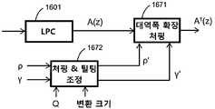
본 발명의 측면에 따라, 오디오 코딩 시스템은 LPC 프레임을 위해 선형 예측 유닛에 의해 생성된 LPC 다항식을 처핑 및/또는 틸팅함으로써 적응적 필터의 특성을 변경하는 지각적 모델링 유닛을 포함한다. 적응적 필터 특성의 변형에 의해 수신된 지각적 모델은 이 시스템에서 많은 목적을 위해 사용될 수 있다. 이것은 예컨대, 양자화 및 장기 예측에서 지각적 가중 함수로서 적용될 수 있다.According to an aspect of the present invention, an audio coding system includes a perceptual modeling unit that changes the characteristics of the adaptive filter by chipping and / or tilting the LPC polynomial generated by the linear prediction unit for the LPC frame. Perceptual models received by modification of the adaptive filter characteristics can be used for many purposes in this system. This can be applied, for example, as a perceptual weighting function in quantization and long term prediction.
본 발명의 다른 독립적인 측면은 입력 신호의 고대역 성분들을 인코딩하는 개별 수단을 제공함으로써 오디오 인코더의 대역폭을 확장하는 것과 관련된다. 일 실시예에 따라, 입력 신호의 고대역 성분을 인코딩하는 고대역 인코더가 제공된다. 바람직하게, 고대역 인코더는 스펙트럼 대역 복제(SBR) 인코더이다. 고대역 인코더에서의 고대역의 별도의 코딩은 변환 영역 신호를 양자화할 때 입력 신호의 저대역에 속하는 성분들에 비해, 고대역에 속하는 변환 영역 신호의 성분들을 인코딩하기 위해 양자화 유닛에서 사용되는, 서로 다른 양자화 스텝들을 허용한다. 더 상세하게는, 양자화기는 비트 레이트를 감소시키는 고대역 인코더에 의해 또한 인코딩되는 고대역 신호 성분의 조악한(coarser) 양자화를 적용할 수 있다.Another independent aspect of the present invention relates to extending the bandwidth of an audio encoder by providing separate means for encoding the high band components of the input signal. According to one embodiment, a highband encoder is provided that encodes the highband component of an input signal. Preferably, the high band encoder is a spectral band replication (SBR) encoder. A separate coding of the high band in the high band encoder is used in the quantization unit to encode components of the transform domain signal belonging to the high band, compared to components belonging to the low band of the input signal when quantizing the transform domain signal, Allow different quantization steps. More specifically, the quantizer can apply coarser quantization of highband signal components that are also encoded by a highband encoder that reduces the bit rate.
다른 실시예에 따라, 입력 신호를 저대역 성분과 고대역 성분으로 분할하는 주파수 분할 유닛이 제공된다. 그런 다음, 고대역 성분은 고대역 인코더에 의해 인코딩되고, 저대역 성분은 선형 예측 유닛에 입력되어 상기 제안한 변환 인코더에 의해 인코딩된다. 바람직하게, 주파수 분할 유닛은 선형 예측 유닛에 입력될 입력 신호를 다운샘플링하도록 구성된 직교 미러 필터 합성 유닛 및 직교 미러 필터뱅크를 포함한다. 직교 미러 필터 뱅크로부터의 신호는 고대역 인코더에 직접 입력된다. 이는 특히 고대역 인코더가 직교 미러 필터뱅크 신호가 직접 공급될 수 있는 스펙트럼 대역 복제 인코더인 경우 매우 유용하다. 또한, 직교 미러 필터뱅크 및 직교 미러 필터 합성 유닛의 결합은 저대역 성분을 위한 프리미엄 다운샘플러로서 동작한다.According to another embodiment, a frequency division unit is provided for dividing an input signal into low band components and high band components. Then, the highband component is encoded by the highband encoder, and the lowband component is input to the linear prediction unit and encoded by the proposed transform encoder. Preferably, the frequency division unit includes an orthogonal mirror filter synthesis unit and an orthogonal mirror filterbank configured to downsample an input signal to be input to the linear prediction unit. The signal from the quadrature mirror filter bank is input directly to the high band encoder. This is particularly useful when the high band encoder is a spectral band replica encoder to which the quadrature mirror filterbank signal can be supplied directly. In addition, the combination of the orthogonal mirror filterbank and the orthogonal mirror filter synthesis unit operates as a premium downsampler for low band components.
저대역과 고대역 사이의 경계는 가변적일 수 있으며, 주파수 분할 유닛은 저대역과 고대역 사이의 크로스오버 주파수를 능동적으로 결정한다. 이는 예컨대, 입력 신호 특성 및/또는 인코더 대역폭 요구사항에 기초하여 적응적인 주파수 할당이 이루어지도록 한다.The boundary between the low band and the high band can be variable, and the frequency division unit actively determines the crossover frequency between the low band and the high band. This allows for adaptive frequency allocation to be made, for example, based on input signal characteristics and / or encoder bandwidth requirements.
다른 측면에 따라, 오디오 코딩 시스템은 고대역 성분을 저역-통과 신호로 전달하는 제2 직교 미러 필터 합성 유닛을 포함한다. 그런 다음, 이 다운-변형된 고주파수 범위는 가능한 저해상도, 즉, 큰 양자화 스텝으로, 제2 변환-기반 인코더에 의해 인코딩될 수 있다. 이는 특히 고주파수 대역이 다른 수단 예컨대, 스펙트럼 대역 복제 인코더에 의해 추가로 잘 인코딩될 때 유용하다. 그러면, 고주파수 대역을 인코딩하는 2가지 방법의 조합이 더 효율적일 수 있다.According to another aspect, the audio coding system includes a second orthogonal mirror filter synthesis unit that delivers the highband components in the lowpass signal. This down-modified high frequency range can then be encoded by the second transform-based encoder with a possible low resolution, i. E. A large quantization step. This is particularly useful when the high frequency band is further well encoded by other means such as a spectral band replica encoder. Then a combination of the two methods of encoding the high frequency band may be more efficient.
동일한 주파수 범위를 커버하는 서로 다른 주파수 표현들은 필요한 비트 레이트를 감소시키기 위해 신호 표현들에서 상관들을 활용하는 신호 표현 결합 유닛에 의해 결합될 수 있다. 신호 표현 결합 유닛은 신호 표현들이 어떻게 결합하는 지를 나타내는 시그널링 데이터를 추가로 발생시킬 수 있다. 이 시그널링 데이터는 서로 다른 신호 표현들로부터 인코딩된 오디오 신호를 재구성하는 디코더로 저장되거나 전송될 수 있다.Different frequency representations covering the same frequency range may be combined by a signal representation combining unit that utilizes correlations in the signal representations to reduce the required bit rate. The signal representation combining unit may further generate signaling data indicating how the signal representations combine. This signaling data can be stored or transmitted to a decoder that reconstructs the encoded audio signal from different signal representations.
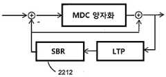
스펙트럼 대역 복제 유닛은 장기 예측 추산물의 고주파수 성분들로 에너지를 유입하는 장기 예측 유닛에 제공될 수 있다. 이는 장기 예측의 효율을 개선시킨다.The spectral band replication unit may be provided to the long term prediction unit that introduces energy into the high frequency components of the long term prediction estimate. This improves the efficiency of long term prediction.
일 실시예에 따라, 우측 및 좌측 채널들을 갖는 스테레오 신호는 입력 신호의 모노 표현을 포함하는 스테레오 신호의 파라메트릭 스테레오 표현을 계산하는 파라메트릭 스테레오 유닛에 입력된다. 이후 이 모노 표현은 제안된 바와 같이, LPC 분석 유닛 및 후속 변환 코더에 입력될 수 있다. 따라서, 오직 모노 표현이 필수적으로 파형 코딩되고, 스테레오 효과가 적은 비트 레이트의 파라메트릭 스테레오 표현으로 달성되는, 스테레오 신호를 인코딩하는 효율적인 수단이 획득된다.According to one embodiment, a stereo signal having right and left channels is input to a parametric stereo unit that calculates a parametric stereo representation of a stereo signal comprising a mono representation of an input signal. This mono representation can then be input to the LPC analysis unit and subsequent transform coder, as suggested. Thus, an efficient means of encoding a stereo signal is obtained, in which only a mono representation is essentially waveform coded and achieved with a parametric stereo representation of a bit rate with less stereo effect.
코딩된 신호의 품질의 추가적인 향상은 주파수/MDCT-영역에서 고조파 신호 성분들을 예측하는 고조파 예측 분석 유닛의 사용에 관련된다.Further improvement in the quality of the coded signal involves the use of a harmonic prediction analysis unit to predict harmonic signal components in the frequency / MDCT-domain.
본 발명의 다른 독립적인 인코더 특정 측면은 가변 프레임 크기들을 다루는 비트 저장소에 관련된다. 가변 길이의 프레임을 코딩할 수 있는 오디오 코딩 시스템에서, 비트 저장소는 프레임들 중 가변 비트들을 분배함으로써 제어된다. 개별 프레임을 위한 합당한 어려움 측정치 및 규정된 크기의 비트 저장소가 주어진 경우, 필요한 일정한 비트 레이트로부터 어떤 벗어남은 비트 저장소 크기에 의해 강제된 버퍼 요구사항에 대한 위반 없이 더 나은 전체 품질을 허용한다. 본 발명은 비트 저장소를 사용하는 개념을 가변 프레임 크기들을 갖는 일반화된 오디오 코덱을 위해 비트 저장소 제어까지로 확장한다. 그러므로, 오디오 코딩 시스템은 프레임의 길이 및 프레임의 어려움 측정치에 기초하여 필터링된 신호의 프레임을 인코딩하도록 승낙된 비트들의 개수를 결정하는 비트 저장소 제어 유닛을 포함할 수 있다. 바람직하게, 비트 저장소 제어 유닛은 서로 다른 프레임 어려움 측정치 및/또는 서로 다른 프레임 크기들에 대한 개별적인 제어 방정식들을 갖는다. 서로 다른 프레임 크기들을 위한 어려움 측정치들은 더 용이하게 비교될 수 있도록 정규화될 수 있다. 가변 레이트 인코더를 위한 비트 할당을 제어하기 위해, 비트 저장소 제어 유닛은 바람직하게, 승인된 비트 제어 알고리즘의 허용된 하한을 가장 큰 허용 프레임 크기를 위한 비트들의 평균 개수로 설정한다.Another independent encoder specific aspect of the present invention relates to a bit store that handles variable frame sizes. In an audio coding system capable of coding a variable length frame, bit storage is controlled by distributing variable bits of the frames. Given a reasonable difficulty measure for an individual frame and a defined size bit store, it allows for better overall quality without violating the buffer requirements imposed by any deviation from the required bit rate. The present invention extends the concept of using bit storage to bit storage control for a generalized audio codec with variable frame sizes. Therefore, the audio coding system can include a bit store control unit that determines the number of bits that are accepted to encode the frame of the filtered signal based on the length of the frame and the difficulty measurement of the frame. Preferably, the bit store control unit has separate control equations for different frame difficulty measurements and / or different frame sizes. Difficulty measurements for different frame sizes can be normalized to allow for easier comparison. To control the bit allocation for the variable rate encoder, the bit store control unit preferably sets the lower limit of the allowed bit control algorithm to the average number of bits for the largest allowed frame size.
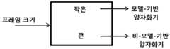
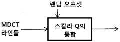
본 발명은 변환 인코더에서 MDCT 라인들을 양자화하는 측면에 관한 것이다. 이 측면은 인코더가 LPC 분석 또는 장기 예측을 사용하는지에 따라 독립적으로 적용가능하다. 이 제안된 양자화 전략은 입력 신호 특성 예컨대, 변환 프레임-크기에 따라 조건화되어 있다. 양자화 유닛은 변환 유닛에 의해 적용되는 프레임 크기에 기초하여, 변환 영역 신호를 모델-기반 양자화기 또는 비모델-기반 양자화기로 인코딩할지를 결정할 수 있다. 바람직하게, 양자화 유닛은 모델-기반 엔트로피 제한형 양자화에 의해 임계값보다 더 작은 프레임 크기를 갖는 프레임을 위해 변환 영역 신호를 인코딩하도록 구성된다. 모델-기반 양자화는 여러 파라미터들에 따라 조건화될 있다. 큰 프레임들은 예컨대, ACC 코덱에서 사용되는 바와 같이, 예컨대, 호프만 기반 엔트로피 코딩으로 예컨대, 스칼라 양자화기에 의해, 양자화될 수 있다.The present invention relates to aspects of quantizing MDCT lines in a transform encoder. This aspect is applicable independently depending on whether the encoder uses LPC analysis or long term prediction. This proposed quantization strategy is conditioned according to input signal characteristics such as transform frame-size. The quantization unit may determine whether to encode the transform domain signal to a model-based or non-model-based quantizer based on the frame size applied by the transform unit. Preferably, the quantization unit is configured to encode the transform domain signal for a frame having a frame size smaller than the threshold by model-based entropy limited quantization. Model-based quantization may be conditioned according to several parameters. Large frames may be quantized, for example by a scalar quantizer, eg, with Hoffman based entropy coding, as used in the ACC codec.
MDCT 라인들의 여러 양자화 방법들 사이의 스위칭이 본 발명의 바람직한 실시예의 다른 측면이다. 여러 변환 크기들에 대해 다른 양자화 정책들을 적용시킴으로써, 코덱이, 변환 영역 코덱에 대해 병렬 혹은 직렬로 동작하는 특정 시간 영역 음성 코더를 가질 필요 없이 MDCT-영역에서 모든 양자화 및 코딩을 수행할 수 있다. 본 발명은 음성과 같은 신호들에 대해, LTP 이득이 있는 경우, 신호가 바람직하게는, 짧은 변환(short transform) 및 모델-기반 양자화기를 사용해 코딩될 수 있음을 시사한다. 모델-기반 양자화기는 특히 짧은 변환에 적합하고, 이후에 설명되는 것과 같이, 여전히 MDCT-영역에서 동작하면서도 입력 신호가 음성 신호일 필요 없이도 시간-영역 음성 특정 벡터 양자화기(VQ)의 장점을 제공한다. 다시 말해, 모델-기반 양자화기가 LTP와 결합하여 짧은 변환 세그먼트에 사용되는 경우, 일반성 손실 없이 그리고 MDCT-영역을 떠날 필요도 없이 전용 시간-영역 음성 코더 VQ의 효율성이 유지된다.Switching between several quantization methods of MDCT lines is another aspect of the preferred embodiment of the present invention. By applying different quantization policies for different transform sizes, the codec can perform all quantization and coding in the MDCT-domain without having to have a particular time-domain speech coder operating in parallel or serially to the transform domain codec. The present invention suggests that for signals such as speech, if there is an LTP gain, the signal may be coded using a short transform and model-based quantizer, preferably. Model-based quantizers are particularly suitable for short transformations and, as will be described later, still operate in the MDCT-domain while still providing the advantages of a time-domain speech specific vector quantizer (VQ) without the need for the input signal to be a speech signal. In other words, when a model-based quantizer is used for short transform segments in combination with LTP, the efficiency of the dedicated time-domain speech coder VQ is maintained without loss of generality and without having to leave the MDCT-domain.
보다 안정적인 음악 신호들을 위해 추가적으로, 오디오 코덱에서 일반적으로 사용되는 것과 같이 상대적으로 큰 크기의 변환, 그리고 큰 변환에 의해 식별되는 희박한 스펙트럼 라인들의 이점들을 취할 수 있는 양자화 정책을 사용하는 것이 바람직하다. 그러므로, 본 발명은 긴 변환(long transform)을 위한 이러한 종류의 양자화 정책을 사용할 것을 제시한다.In addition, for more stable music signals, it is desirable to use a quantization policy that can take advantage of the relatively large magnitude of the transform, as is commonly used in audio codecs, and the sparse spectral lines identified by the large transform. Therefore, the present invention proposes to use this kind of quantization policy for long transform.
따라서, 프레임 크기의 함수로서 양자화 정책의 스위칭은 변환 크기의 선택만으로, 코덱으로 하여금 전용 음성 코덱의 특성들, 그리고 전용 오디오 코덱의 특성들 모두를 유지할 수 있도록 한다. 이것은, 낮은 레이트에서 동일하게 음성 및 오디오 신호들을 처리하기 위해 노력하는 종래 기술 시스템들에서의 모든 문제점들을 회피하는데, 이것은 이러한 시스템들이, 필연적으로 시간-영역 코딩(음성 코더)을 주파수 영역 코딩(오디오 코더)과 효과적으로 결합하는 문제점들 및 어려움들과 부딪히기 때문이다.Thus, switching of the quantization policy as a function of frame size allows the codec to retain both the characteristics of the dedicated voice codec and the characteristics of the dedicated audio codec with only a choice of transform size. This avoids all the problems in prior art systems that strive to equally process speech and audio signals at low rates, which inevitably leads to time-domain coding (voice coder) in frequency domain coding (audio). The problems and difficulties of effectively combining with the coder.
본 발명의 또 다른 측면에 따르면, 양자화는 적응적 스텝 크기들을 사용한다. 바람직하게는, 변환 영역 신호의 성분들에 대한 양자화 스텝 크기(들)은 선형 예측 및/또는 장기 예측 파라미터들을 기초로 하여 조정된다. 양자화 스텝 크기(들)은 또한 주파수 의존적으로 구성된다. 본 발명의 실시예들에서는 양자화 스텝 크기가, 적응적 필터의 다항식, 코딩 레이트 제어 파라미터, 장기 예측 이득 값, 및 입력 신호 변동(variance) 중 적어도 하나에 기초하여 결정된다. According to another aspect of the present invention, quantization uses adaptive step sizes. Preferably, the quantization step size (s) for the components of the transform domain signal are adjusted based on linear prediction and / or long term prediction parameters. The quantization step size (s) are also frequency dependent. In embodiments of the present invention, the quantization step size is determined based on at least one of a polynomial of the adaptive filter, a coding rate control parameter, a long term predictive gain value, and an input signal variation.
본 발명의 또 다른 측면은 장기예측(LTP), 특히 MDCT- 영역에서의 장기 예측, MDCT 프레임 조정된 LTP, 및 MDCT 가중된 LTP 검색에 관련된다. 이러한 측면들은 LPC 분석이 변환 코더의 현재 업스트림인지 여부와 무관하게 적용가능하다.Another aspect of the invention relates to long term prediction (LTP), in particular long term prediction in the MDCT-region, MDCT frame-adjusted LTP, and MDCT weighted LTP search. These aspects are applicable regardless of whether the LPC analysis is currently upstream of the transform coder.
일 실시예에 따르면, 장기 예측 유닛은 필터링된 신호의 현재 프레임에 가장 잘 부합하는 필터링된 신호의 재구성된 세그먼트를 특정하는 래그(lag) 값을 결정하는 장기 예측 추출기를 포함한다. 장기 예측 이득 추산기는 필터링된 신호의 선택된 세그먼트의 신호에 적용된 이득 값을 추산할 수 있다. 바람직하게는, 래그 값 및 이득 값은 지각적 영역에서 변환된 입력 신호에 대한 장기 예측 추산의 차이와 관계되는 왜곡 기준을 최소화하기 위해 결정된다. 왜곡 기준은 지각적 영역에서 변환된 입력 신호에 대한 장기 예측 추산물의 차이에 관련될 수 있다. 바람직하게, 왜곡 기준은 지각 영역에서 래그 값 및 이득 값을 검색함으로써 최소화될 수 있다. 변형된 선형 예측 다항식은 왜곡 기준을 최소화할 때 MDCT-영역 등화 이득 커브로서 적용될 수 있다.According to one embodiment, the long term prediction unit comprises a long term prediction extractor that determines a lag value that specifies a reconstructed segment of the filtered signal that best matches the current frame of the filtered signal. The long term predictive gain estimator may estimate a gain value applied to the signal of the selected segment of the filtered signal. Preferably, the lag value and the gain value are determined to minimize the distortion criteria associated with the difference in long term prediction estimates for the transformed input signal in the perceptual domain. The distortion criterion may be related to the difference in long term prediction estimates for the transformed input signal in the perceptual domain. Preferably, the distortion criteria can be minimized by searching for lag values and gain values in the perceptual region. The modified linear predictive polynomial can be applied as an MDCT-domain equalization gain curve when minimizing distortion criteria.
장기 예측 유닛은 LTP 버퍼로부터 변환 영역으로 세그먼트들의 재구성된 신호를 변환하는 변환 유닛을 포함할 수 있다. MDCT 변환의 효율적인 구현을 위해, 변환은, 바람직하게는 타입-4 이산-코싸인 변환이다.The long term prediction unit may comprise a transform unit for transforming the reconstructed signal of the segments from the LTP buffer to the transform region. For efficient implementation of the MDCT transformation, the transformation is preferably a type-4 discrete-cosine transformation.
가상 벡터들이 래그 값이 MDCT 프레임 길이보다 작을 때 재구성된 신호의 확장된 세그먼트를 생성하는데 사용될 수 있다. 가상 벡터들은 바람직하게 재구성된 신호의 생성된 세그먼트를 정제(refine)하기 위해 반복적인 포갬 펼침 프로시저에 의해 생성된다. 따라서, 재구성된 신호의 기존 세그먼트들이 장기 예측의 래그 검색 절차 동안 발생되지 않는다.Virtual vectors may be used to generate an extended segment of the reconstructed signal when the lag value is less than the MDCT frame length. The virtual vectors are preferably generated by an iterative foaming unfolding procedure to refine the resulting segment of the reconstructed signal. Thus, existing segments of the reconstructed signal are not generated during the lag search procedure of long term prediction.
장기 예층 버퍼의 재구성된 신호는 변환 유닛이 시간-워핑된 신호들 상에서 동작할 때 시간-워핑된 커브에 기초하여 재샘플링된다. 이는 시간-워핑된 MDCT를 매칭하는 시간-워핑된 LTP 추출을 허용한다.The reconstructed signal of the long-term preliminary buffer is resampled based on the time-warped curve when the transform unit is operating on time-warped signals. This allows time-warped LTP extraction to match time-warped MDCT.
일 실시예에 따라, 장기 예측 래그 및 이득 값들을 인코딩하는 가변 레이트 인코더가 낮은 비트레이트를 달성하기 위해 제공될 수 있다. 또한, 장기 예측 유닛은 예컨대, 잡음 또는 일시적인 신호들에 대해 예측 정확도를 향상시키도록 노이즈 벡터 버퍼 및/또는 펄스 벡터 버퍼를 포함할 수 있다.According to one embodiment, a variable rate encoder that encodes long term prediction lag and gain values may be provided to achieve low bitrate. In addition, the long term prediction unit may include a noise vector buffer and / or a pulse vector buffer, for example, to improve prediction accuracy for noise or transient signals.
장기 예측 파라미터들, 고조파 예측 파라미터들 및 시간-워프 파라미터들과 같은 피치 관련 정보를 통합적으로 인코딩하는 통합 코딩 유닛이 제공될 수 있다. 통합 인코딩은 이들 파라미터들에서 상관을 이용함으로써 필요한 비트 레이트를 또한 감소시킬 수 있다.An integrated coding unit may be provided that integrally encodes pitch related information such as long term prediction parameters, harmonic prediction parameters and time-warp parameters. Unified encoding can also reduce the required bit rate by using correlation in these parameters.
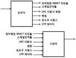
본 발명의 다른 측면은 상기 인코더의 실시예에 의해 제공된 비트스트림을 디코딩하는 오디오 디코더에 관련된다. 오디오 디코더는 입력 비트스트림의 프레임을 역-양자화하는 역-양자화 유닛; 변환 영역 신호를 역으로 변환하는 역-변환 유닛; 상기 역-양자화된 프레임의 추산물을 결정하는 장기 예측 유닛; 상기 변환 영역 신호를 생성하기 위해 상기 장기 예측 추산물과 상기 역-양자화된 프레임을 상기 변환 영역에서 결합하는 변환 영역 신호 결합 유닛; 및 상기 역으로 변환된 변환 영역 신호를 필터링하는 선형 예측 유닛을 포함한다.Another aspect of the invention relates to an audio decoder for decoding a bitstream provided by an embodiment of the encoder. The audio decoder includes an inverse quantization unit that inversely quantizes a frame of an input bitstream; An inverse-conversion unit for inverting the transform region signal; A long term prediction unit for determining an estimate of the de-quantized frame; A transform region signal combining unit for combining the long term prediction estimate and the de-quantized frame in the transform region to produce the transform region signal; And a linear prediction unit for filtering the inverse transformed transform domain signal.
추가적으로, 디코더는 디코더에 대해 앞서 개시된 바와 같은 많은 측면들을 포함할 수 있다. 일반적으로, 디코더는 인코더의 동작을 미러링할(mirror) 것인데, 물론 몇몇 동작들은 인코더에서만 수행되어지고 디코더 내에 상응하는 구성요소들을 가지지 않을 것이지만 말이다. 따라서, 인코더에 대해 개시된 것들은 특별히 다르게 언급되지 않는 한 디코더에도 마찬가지로 적용 가능하다 할 것이다.In addition, the decoder may include many aspects as disclosed above for the decoder. In general, the decoder will mirror the operation of the encoder, although of course some operations will be performed only at the encoder and will not have corresponding components in the decoder. Thus, those disclosed for the encoder would likewise be applicable to the decoder unless specifically stated otherwise.
본 발명의 상기한 측면들은 디바이스, 장치, 방법, 또는 프로그램 가능한 디바이스 상에서 동작하는 컴퓨터 프로그램에 의해 구현될 수 있다. 본 발명의 측면들은 또한 신호, 데이터 구조 및 비트스트림에서 구현될 수 있다.The foregoing aspects of the invention may be implemented by a device, apparatus, method, or computer program running on a programmable device. Aspects of the invention may also be implemented in signals, data structures, and bitstreams.
따라서, 본 출원은 추가로 오디오 인코딩 방법 및 오디오 디코딩 방법을 개시한다. 예시적인 오디오 인코딩 방법은 적응적 필터에 기반하여 입력 신호를 필터링하는 단계; 상기 필터링된 입력 신호의 프레임을 변환 영역으로 변환하는 단계; 변환 영역 신호를 양자화하는 단계; 상기 필터링된 입력 신호의 이전 세그먼트의 재구성에 기초하여 상기 필터링된 입력 신호의 상기 프레임을 추산하는 단계; 및 상기 변환 영역 신호를 생성하기 위해 상기 장기 예측 추산물과 상기 변환된 입력 신호를 상기 변환 영역에서 결합하는 단계를 포함한다.Accordingly, the present application further discloses an audio encoding method and an audio decoding method. An exemplary audio encoding method includes filtering an input signal based on an adaptive filter; Converting a frame of the filtered input signal into a transform region; Quantizing the transform domain signal; Estimating the frame of the filtered input signal based on reconstruction of a previous segment of the filtered input signal; And combining the long term prediction estimate with the transformed input signal in the transform domain to produce the transform domain signal.
예시적인 오디오 디코딩 방법은 입력 비트스트림의 프레임을 역-양자화하는 단계; 변환 영역 신호를 역변환하는 단계; 상기 역-양자화된 프레임의 추산물을 결정하는 단계; 상기 변환 영역 신호를 생성하기 위해 상기 장기 예측 추산물과 상기 역-양자화된 프레임을 상기 변환 영역에서 결합하는 단계; 상기 변환된 변환 영역 신호를 역으로 필터링하는 단계; 및 재구성된 오디오 신호를 출력하는 단계를 포함한다.An example audio decoding method includes de-quantizing a frame of an input bitstream; Inversely transforming the transform domain signal; Determining an estimate of the de-quantized frame; Combining the long term prediction estimate with the dequantized frame in the transform region to produce the transform region signal; Inversely filtering the transformed transform region signal; And outputting the reconstructed audio signal.
이들은 단지, 본 출원에 의해 시사되고 아래의 상세한 실시예들로부터 통상의 지식을 가진 자가 도출할 수 있는 바람직한 오디오 인코딩/디코딩 방법들 및 컴퓨터 프로그램들의 실시예들일 뿐이다.These are merely embodiments of preferred audio encoding / decoding methods and computer programs suggested by the present application and which can be derived by one of ordinary skill in the art from the detailed embodiments below.
본 발명에 따라 특정 신호에 특별히 맞춰진 시스템의 품질과 동등하거나 그보다 나은 품질 레벨에서 임의의 오디오 신호들을 효과적으로 코딩할 수 있다.According to the invention it is possible to effectively code any audio signals at a quality level equal to or better than the quality of a system specifically tailored to a particular signal.
이제 첨부의 도면들을 참조하여 본 발명의 범위 또는 사상을 한정하지 않으며, 본 발명이 예시적인 실시예들에 의해 설명될 것이다.
도 1은 본 발명에 따른 인코더 및 디코더의 바람직한 일 실시예를 나타낸다.
도 2는 본 발명에 따른 인코더 및 디코더의 보다 자세한 도면을 도시한다.
도 3은 본 발명에 따른 인코더의 다른 실시예를 나타낸다.
도 4는 본 발명에 따른 인코더의 바람직한 일 실시예를 나타낸다.
도 5는 본 발명에 따른 디코더의 바람직한 일 실시예를 나타낸다.
도 6은 본 발명에 따라 MDCT 라인들 인코딩 및 디코딩의 바람직한 일 실시예를 나타낸다.
도 7은 SBR 인코더와 결합된 본 발명의 바람직한 일 실시예를 나타낸다.
도 8은 스테레오 시스템의 바람직한 일 실시예를 나타낸다.
도 9는 본 발명에 따른 코어 코더와 고주파수 재구성 코딩의 더 복잡한 통합에 대한 바람직한 일 실시예를 나타낸다.
도 10은 본 발명에 따른 SBR 코딩과 코어 코더의 결합의 바람직한 일 실시예를 도시한다.
도 11은 본 발명에 따른 인코더 및 디코더의 바람직한 실시예, 그리고 한 쪽에서 다른 쪽으로 전송되는 관련 제어 데이터의 실시예들을 도시한다.
도 11a는 본 발명의 일 실시예에 따른 인코더의 측면들의 다른 실시예이다.
도 12은 본 발명의 일 실시예에 따른 윈도우 시퀀스의 일 실시예 및 LDC 데이터 및 MDCT 데이터 사이의 관계를 도시한다.
도 13는 본 발명에 따른 스케일-인자 데이터 및 LPC 데이터의 결합을 도시한다.
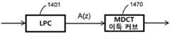
도 14은 본 발명에 따라 LPC 다항식들을 MDCT 이득 커브로 번역하는 것의 바람직한 일 실시예를 도시한다.
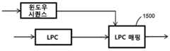
도 15은 본 발명에 따라, 고정 업데이트 레이트 LPC 파라미터들을 적응적 MDCT 윈도우 시퀀스 데이터로 매핑하는 바람직한 일 실시예를 도시한다.
도 16는 본 발명에 따라, 변환 크기 및 양자화기의 종류에 기초하여 지각적 가중 필터 연산을 적용하는 것의 바람직한 일 실시예를 도시한다.
도 17은 본 발명에 따라, 프레임 크기에 의존하는 양자화기를 조정하는 것의 바람직한 일 실시예를 도시한다.
도 18는 본 발명에 따라, 프레임 크기에 의존하는 양자화기를 조정하는 것의 바람직한 일 실시예를 도시한다.
도 19는 본 발명의 바람직한 실시예에 따라, LPC 및 LTP 데이터의 함수로서 양자화 스텝 크기를 조정하는 것의 바람직한 일 실시예를 도시한다.
도 19a는 델타 조정 모듈에 의해 어떻게 델타-커브가 LPC 및 LTP 파라미터들로부터 도출되는지를 나타낸다.
도 20은 본 발명에 따라, 랜덤 오프셋을 활용하는 모델-기반 양자화기의 바람직한 일 실시예를 도시한다.
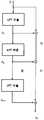
도 21은 본 발명에 따른 모델-기반 양자화기의 바람직한 일 실시예를 도시한다.
도 21a는 본 발명에 따른 모델-기반 양자화기의 다른 바람직한 일 실시예를 도시한다.
도 22는 본 발명에 따른 LTP 루프에서의 SBR 모듈을 이용한 바람직한 일 실시예를 도시한다.
도 23a는 본 발명의 일 실시예에서의 MDCT 변환의 인접 윈도우들을 도해적으로 도시한다.
도 23b는 4개의 서로 다른 MDCT 윈도우 형상들을 이용한 본 발명의 일 실시예를 나타낸다.
도 23c는 본 발명의 일 실시예에 따른 윈도우 시퀀스 인코딩의 예를 나타낸다.
도 24는 본 발명에 따라, MDCT-영역에서의 고조파 예측의 바람직한 일 실시예를 나타낸다.
도 25는 본 발명에 따른 LTP 추출 프로세스를 나타낸다.
도 25a는 MDCT 적합된 LTP 추출 프로세스를 나타낸다.
도 25b는 최초 LTP 추출된 신호의 반복적인 정제를 나타낸다.
도 25c는 정제 유닛의 다른 구현을 나타낸다.
도 25d는 정제 유닛의 또 다른 구현을 나타낸다.
도 26은 본 발명에 따라 고조파 예측, LTP 및 시간-워프를 위한 제어 데이터를 결합하는 바람직한 일 실시예를 나타낸다.
도 27은 본 발명에 따라, 노이즈 및 펄스 버퍼들에서 LTP 검색을 확장하는 바람직한 일 실시예를 나타낸다.
도 28a는 비트 저장소 제어의 기본 개념을 나타낸다.
도 28b는 본 발명에 따른 가변 프레임 크기들을 위한 비트 저장소 제어의 개념을 나타낸다.
도 29는 본 발명에 따라 시간-워핑된 MDCT에 관련한 LTP 검색 및 응용을 나타낸다.
도 29a는 시간-워핑된 MDCT 분석의 효과를 나타낸다.
도 30은 본 발명에 따른 MDCT 및 QMF 영역에서 결합된 SBR을 나타낸다.The present invention will now be described with reference to the accompanying drawings, without limiting the scope or spirit of the invention.
1 shows a preferred embodiment of an encoder and a decoder according to the invention.
2 shows a more detailed view of an encoder and a decoder according to the invention.
3 shows another embodiment of an encoder according to the invention.
4 shows a preferred embodiment of the encoder according to the invention.
5 shows a preferred embodiment of the decoder according to the invention.
6 illustrates one preferred embodiment of MDCT lines encoding and decoding in accordance with the present invention.
Figure 7 shows one preferred embodiment of the present invention combined with an SBR encoder.
8 shows one preferred embodiment of a stereo system.
Figure 9 illustrates one preferred embodiment for more complex integration of the core coder and high frequency reconstruction coding according to the present invention.
Figure 10 shows a preferred embodiment of the combination of SBR coding and core coder according to the present invention.
Figure 11 shows a preferred embodiment of the encoder and decoder according to the invention and embodiments of the relevant control data transmitted from one side to the other.
11A is another embodiment of aspects of an encoder according to an embodiment of the present invention.
12 illustrates an embodiment of a window sequence and a relationship between LDC data and MDCT data according to an embodiment of the present invention.
13 illustrates a combination of scale-factor data and LPC data according to the present invention.
Figure 14 illustrates one preferred embodiment of translating LPC polynomials into MDCT gain curves in accordance with the present invention.
15 illustrates one preferred embodiment for mapping fixed update rate LPC parameters to adaptive MDCT window sequence data, in accordance with the present invention.
Figure 16 illustrates one preferred embodiment of applying perceptual weighted filter operations based on the transform size and the type of quantizer, in accordance with the present invention.
Figure 17 shows one preferred embodiment of adjusting the quantizer depending on the frame size, in accordance with the present invention.
18 illustrates one preferred embodiment of adjusting the quantizer depending on the frame size, in accordance with the present invention.
19 illustrates one preferred embodiment of adjusting the quantization step size as a function of LPC and LTP data, in accordance with a preferred embodiment of the present invention.
19A shows how the delta-curve is derived from the LPC and LTP parameters by the delta adjustment module.
20 illustrates one preferred embodiment of a model-based quantizer utilizing a random offset, in accordance with the present invention.
Figure 21 illustrates one preferred embodiment of a model-based quantizer according to the present invention.
21A shows another preferred embodiment of a model-based quantizer according to the present invention.
Figure 22 illustrates one preferred embodiment using an SBR module in an LTP loop according to the present invention.
23A graphically illustrates adjacent windows of an MDCT transform in one embodiment of the present invention.
Figure 23B illustrates an embodiment of the present invention using four different MDCT window shapes.
23C illustrates an example of window sequence encoding according to an embodiment of the present invention.
Figure 24 shows one preferred embodiment of harmonic prediction in the MDCT-region, in accordance with the present invention.
25 shows an LTP extraction process according to the present invention.
25A shows an MDCT fitted LTP extraction process.
25B shows repeated purification of the original LTP extracted signal.
25C shows another implementation of a purification unit.
25D shows another implementation of a purification unit.
Figure 26 shows one preferred embodiment of combining control data for harmonic prediction, LTP and time-warp in accordance with the present invention.
Figure 27 illustrates one preferred embodiment of extending LTP search in noise and pulse buffers, in accordance with the present invention.
28A illustrates the basic concept of bit storage control.
28B illustrates the concept of bit storage control for variable frame sizes in accordance with the present invention.
29 illustrates LTP search and application in relation to time-warped MDCT in accordance with the present invention.
29A shows the effect of time-warped MDCT analysis.
30 shows SBR bound in the MDCT and QMF regions according to the present invention.
아래 설명되는 실시예들은, 오디오 인코더 및 디코더를 위한 본 발명의 원리들에 대해 단지 도시적이다. 여기 설명된 방식들 및 상세사항들의 변형 및 변화들이 통상의 지식을 가진 자에게 명백할 것임이 이해되어야 한다. 그러므로, 첨부되는 특허 청구항들의 범주에 의해서만 한정될 뿐 여기서의 실시예들의 서술 및 설명의 방법으로 제시된 특정 상세사항들에 의해 한정되지 않는 것이 의도된다. 실시예들의 유사한 요소들은 유사한 참조 기호들에 의해 표시된다.The embodiments described below are merely illustrative of the principles of the invention for an audio encoder and decoder. It should be understood that variations and changes in the manners and details described herein will be apparent to those skilled in the art. It is the intention, therefore, to be limited only by the scope of the appended patent claims and not by the specific details presented by way of description and description of the embodiments herein. Similar elements of the embodiments are indicated by similar reference symbols.
도 1에서 인코더(101) 및 디코더(102)가 형상화된다. 인코더(101)는 시간-영역 입력 신호를 취하고 연속적으로 디코더(102)로 전송되는 비트스트림(103)을 생성한다. 디코더(102)는 수신된 비트스트림(103)에 기초하여 출력 파형을 생성한다. 출력 신호는 심리음향적으로 원래의 입력 신호와 유사하다.In FIG. 1 the
도 2에서 인코더(200) 및 디코더(210)의 바람직한 실시예가 도시된다. 인코더(200)에서의 입력 신호는 제1 프레임 길이를 가지는 LPC 프레임에 대해 백색화된 잔여 신호 및 상응하는 선형 예측 파라미터들을 생성하는 LPC(선형 예측 코딩) 모듈(201)을 통과한다. 추가적으로, 이득 정규화가 LPC 모듈(201) 내에 포함될 수 있다. LPC로부터의 잔여 신호가 제2 가변 프레임 길이 상에서 동작하는 MDCT(Modified Discrete Cosine Transform, 변형 이산 코싸인 변환) 모듈(202)에 의해 주파수 영역으로 변환된다. 도 2에 도시된 인코더(200)에, LTP(Long Term Prediction, 장기 예측) 모듈(205)이 포함된다. LTP는 본 발명의 추가적인 실시예에서 상세히 설명될 것이다. MDCT 라인들이 양자화되고(203), 또한, 디코더(210)에대해 이용 가능할 디코딩된 출력의 복사본을 LTP 버퍼로 공급하기 위해 역-양자화된다(204). 양자화 왜곡으로 인해, 이러한 복사본은 개별적인 입력 신호의 재구성이라 불린다. 도 2의 하단에서 디코더(210)가 도시된다. 디코더(210)는 양자화된 MDCT 라인들을 취하여, 이들을 역-양자화하고(211), LTP 모듈(214)로부터의 기여분을 가산하며, 역 MDCT 변환(212)을 수행하고, LPC 합성 필터(213)가 뒤를 따른다.In Fig. 2 a preferred embodiment of the
상술한 실시예들의 중요한 측면은, 비록 LPC가 고유의 (하나의 실시예에서는 고정적인) 프레임 크기를 가지고 LPC 파라미터들 또한 코딩되지만, MDCT 프레임이 단지 코딩을 위한 기본 유닛이라는 점이다. 이 실시예는 변환 코더로부터 시작하여 음성 코더로부터 근본적인 예측 및 형성(shaping) 모듈을 소개한다. 이후 설명될 바와 같이, MDCT 프레임 크기는 가변적이고, 전체 블록에 대해 최적의 MDCT 윈도우 시퀀스를 결정하고 단순화한 지각적 엔트로피 비용 함수를 최소화함으로써 입력 신호의 블록에 대해 조정된다. 이는 최적의 시간/주파수 제어를 유지하기 위한 스케일링을 허용한다. 또한, 제안된 통합된 구조는 다른 코딩 패러다임들의 스위칭된 또는 계층화된 결합들을 피한다.An important aspect of the above-described embodiments is that although the LPC has its own (fixed in one embodiment) frame size and the LPC parameters are also coded, the MDCT frame is just the basic unit for coding. This embodiment introduces the fundamental prediction and shaping module from the speech coder, starting with the transform coder. As will be described later, the MDCT frame size is variable and adjusted for blocks of the input signal by determining the optimal MDCT window sequence for the entire block and minimizing the simplified perceptual entropy cost function. This allows scaling to maintain optimal time / frequency control. In addition, the proposed integrated structure avoids switched or layered combinations of other coding paradigms.
도 3에서, 인코더(300)의 부분들이 보다 자세히 도해적으로 서술된다. 도 2의 인코더에서 LPC 모듈(201)로부터 출력되는 바와 같은 백색화된 신호가 MDCT 필터뱅크(302)로 입력된다. MDCT 분석은, 선택적으로 신호(만약 신호가 잘-규정된 피치를 가지고 주기적이라면)의 피치가 MDCT 변환 윈도우 상에서 일정한 것을 확실하도록 하는 시간-워핑된 MDCT 분석일 수 있다.In FIG. 3, portions of
도 3에서, LTP 모듈(310)이 보다 자세히 설명된다. 이것은 이전의 출력 신호 세그먼트들의 재구성된 시간-영역 샘플들을 유지하는 LTP 버퍼(311)를 포함한다. LTP 추출기(312)는 현재 입력 세그먼트가 주어진 LTP 버퍼(311)에서 가장 잘 매칭되는 세그먼트를 찾는다. 이 세그먼트가 양자화기(303)로 현재 입력되는 세그먼트로부터 감산되기 전에, 적합한 이득 값이 이득 유닛(313)에 의해 상기 세그먼트에 적용된다. 분명히, 양자화에 앞서 감산을 수행하기 위해서는, LTP 추출기(312)가 또한 선택된 신호 세그먼트를 MDCT-영역으로 변환시킨다. LTP 추출기(312)는, 재구성된 이전 출력 신호 세그먼트를 변환된 MDCT-영역 입력 프레임과 결합시킬 때 지각적 영역에서 에러 함수를 최소화하는 최상의 이득 및 래그 값들을 검색한다. 예를 들어, LTP 모듈(310)로부터의 변환된 재구성된 세그먼트 및 변환된 입력 프레임(즉, 감산 후의 잔여 신호) 간의 평균제곱에러(MSE) 함수가 최적화된다. 이러한 최적화는 주파수 성분들(즉, MDCT 라인들)이 그 지각적 중요성에 따라 가중되는 지각적 영역에서 수행될 수 있다. LTP 모듈(310)은 MDCT 프레임 단위로 동작하고 인코더(300)는, 예를 들어 양자화 모듈(303)에서의 양자화를 위해, 한번에 하나의 MDCT 프레임 잔여물을 고려한다. 래그 및 이득 검색은 지각적 영역에서 수행될 수 있다. 선택적으로, LTP는 주파수 선택적일 수 있는데, 즉, 주파수 상에서 이득 및/또는 래그를 조정한다. 역 양자화 유닛(304) 및 역 MDCT 유닛(306)이 도시된다. MDCT는 이후에 설명되는 바와 같이 시간-워핑될 수 있다.In FIG. 3, the
도 4에서, 인코더(400)의 다른 실시예가 도시된다. 도 3에 더하여, LPC 분석(401)이 명확화를 위해 포함된다. 선택된 신호 세그먼트를 MDCT-영역으로 변환하는 데 사용되는 DCT-IV 변환(414)이 도시된다. 부가적으로, LTP 세그먼트 선택을 위한 최소 에러를 계산하기 위한 여러 방법들이 도시된다. 도 4에 도시된 바와 같은 잔여 신호의 최소화(도 4에서 LTP2로 표시된)에 더불어, LTP 버퍼(411)에서의 저장을 위해 재구성된 시간-영역 신호로 역으로 변환되기 전에 변환된 입력 신호와 역-양자화된 MDCT-영역 신호 간의 차이의 최소화가 도시된다(LTP3으로 표시된). 이러한 MSE 함수의 최소화가, LTP 버퍼(411)에서의 저장을 위해, LTP 기여분을 변환된 입력 신호와 재구성된 입력 신호의 (가능한한) 최적의 유사도를 향해 인도할 것이다. 다른 대체적인 에러 함수(LTP1으로 표시되는)가 시간-영역에서의 이러한 신호들의 차이에 기초한다. 이 경우, LPT 필터링된 입력 프레임 및 LTP 버퍼(411)에서의 상응하는 시간-영역 재구성 간의 MSE가 최소화된다. MSE는, LPC 프레임 크기와는 다를 것인, MDCT 프레임 크기에 기초하여 유리하게 계산된다. 추가적으로, 양자화기 및 역-양자화기 블록들은 도 6에서 서술될 바와 같은 양자화와는 별개인 추가적인 모듈들을 포함할 수 있는 스펙트럼 인코딩 블록(403) 및 스펙트럼 디코딩 블록들(404)("스펙트럼 인코딩" 및 "스펙트럼 디코딩")에 의해 대체된다. 다시, MDCT 및 역 MDCT는 시간-워핑될 수 있다(WMDCT, IWMDCT).In FIG. 4, another embodiment of an
도 5에서 제안된 디코더(500)가 도시된다. 수신된 비트스트림으로부터의 스펙트럼 데이터가 역으로 양자화(511)되고 LTP 버퍼(515)로부터 LTP 추출기에 의해 제공되는 LTP 기여분과 함께 가산된다. 디코더(500)에 LTP 추출기(516) 및 LTP 이득 유닛(517) 또한 도시된다. 합산된 MDCT 라인들은 MDCT 합성 모듈에 의해 시간-영역으로 합성되고, 시간 영역 신호는 LPC 합성 필터(513)에 의해 스펙트럼적으로 형성된다. 선택적으로, MDCT 합성은 시간-워핑된 MDCT가 될 수 있으며, 그리고/또는 LPC 합성 필터링은 주파수 워핑될 수 있다.The
주파수-워핑된 LPC는 LPC 필터 파라미터들을 결정할 때 LPC 에러 기여분의 주파수 선택적인 제어를 허용하도록 주파수의 비균일 샘플링에 기반한다. 보통의 LPC는 LPC 다항식이 스펙트럼 피크들의 영역에서 거의 정확하도록 선형 주파수 축 상에서 MSE를 최소화하는 것에 기초하더라도, 주파수-워핑된 LPC는 LPC 필터 파라미터들을 결정할 때 주파수 선택적인 관점을 허용한다. 예를 들어, 16 또는 24 kHz 샘플링 레이트와 같은 높은 대역폭 상에서 동작할 때 주파수 축을 워핑하는 것은 4 kHz 까지의 주파수들과 같은 더 낮은 주파수 대역 상에서 LPC 다항식의 정확도에 집중할 수 있도록 한다.Frequency-warped LPC is based on non-uniform sampling of frequencies to allow frequency selective control of LPC error contributions when determining LPC filter parameters. Although ordinary LPC is based on minimizing MSE on the linear frequency axis such that the LPC polynomial is nearly accurate in the region of spectral peaks, frequency-warped LPC allows a frequency selective view when determining LPC filter parameters. For example, warping the frequency axis when operating on higher bandwidths, such as 16 or 24 kHz sampling rates, allows focusing on the accuracy of the LPC polynomial on lower frequency bands, such as frequencies up to 4 kHz.
도 6에서는 도 4의 "스펙트럼 인코딩" 및 "스펙트럼 디코딩" 블록들(403, 404)이 보다 자세히 설명된다. 도면에서 우측에 도시된 "스펙트럼 인코딩" 블록(603)은 일 실시예에서, 하모닉 예측 분석 모듈(610), TNS(Temporal Noise Shaping) 분석 모듈(611), 후속하는 MDCT 라인들의 스케일-인자 스케일링 모듈(612), 그리고 마지막으로 인코딩 라인들 모듈(613)의 라인들의 양자화 및 인코딩을 포함한다. 도면에서 좌측에 도시된 디코더 "스펙트럼 디코딩" 블록(604)은 역 처리를 수행한다, 즉, 수신된 MDCT 라인들이 디코딩 라인들 모듈(620)에서 역-양자화되고 스케일링이 스케일인자(SCF) 스케일링 모듈(621)에 의해 역-수행된다. TNS 합성(622) 및 하모닉 예측 합성(623)이 적용되는데, 이하 설명된다.In FIG. 6, the “spectrum encoding” and “spectrum decoding” blocks 403 and 404 of FIG. 4 are described in more detail. The “spectrum encoding”
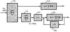
도 7에서, 본 발명의 다른 바람직한 실시예가 도시되어 있다. 이미 도시된 LPC(701), MDCT 양자화(704) 및 LTP(705)에 추가하여, QMF 분석 모듈(710) 및 QMF 합성 모듈(711)이 SBR(Spectral Band Replication) 모듈(712)와 함께 추가되어 있다. QMF(Quadrature Mirror Filter) 필터뱅크는 이 특정 실시예(64)에서 어떤 개수의 서브밴드들를 갖는다. 복소 QMF 필터뱅크는 사용된 프로토타입 필터에 주어진 에일리어싱 제거 레벨(aliasing rejection level) 이상으로 주파수 영역 에일리어싱을 유도함이 없이 서브밴드들의 독립적인 조작을 허용한다. 이 특정 실시예(32)에서, 이후 어떤 개수의 낮은(주파수에서) 서브밴드들이 시간-영역으로 합성되며 그에 따라, 여기에서 2의 인자만큼 다운샘플링된 신호를 생성한다. 이는 전술한 바와 같이, 인코더 모듈들에 대한 입력 신호이다. QMF 분석 및 합성 모듈들을 재샘플러(resampler)로서 사용하는 것은, LPC가 감소된 대역폭에 따라서만 동작하고 다음 변환 코더가 또한 감소된 대역폭 상에서 동작하는 것을 보장한다. 더 높은(32) 서브밴드들은 높은 대역의 원래의 신호로부터 관련 SBR 파라미터들을 추출하는 SBR 인코더 모듈(712)로 전송된다. 다르게는, 입력 신호는 QMF 분석 모듈에 공급되고, 그런 다음 SBR 인코더 및, 전술한 바와 같이 변환 인코더 모듈들을 위한 다운샘플링된 신호를 생성하는 다운샘플링 모듈에 연결된다.In Fig. 7, another preferred embodiment of the present invention is shown. In addition to the
SBR(스펙트럼 대역 복제)은 스펙트럼의 높은 주파수 부분을 코딩하는 효과적인 방식을 제공한다. 이는 낮은 주파수들로부터 오디오 신호의 높은 주파수들과 적은 양의 추가적인 제어 정보를 재생성한다. SBR 방법은 코어(core) 코더 대역폭의 감소를 가능하게 하며, SBR 기술은 주파수 범위를 코딩하는데 파형 코더 보다 상당히 낮은 비트레이트를 필요로 하기 때문에, 코딩 이득은 전체 오디오 대역폭을 유지하면서 파형 코어 코더에 할당된 비트레이트를 감소시킴으로써 달성될 수 있다. 자연적으로, 이는 코어 코더와 SBR 부분 사이에 교차하는 주파수를 적게 함으로써 전체 데이터 레이트를 거의 연속적으로 감소시킬 가능성을 가져온다.Spectrum band replication (SBR) provides an effective way of coding the high frequency portion of the spectrum. This regenerates high frequencies and a small amount of additional control information of the audio signal from low frequencies. The SBR method enables the reduction of core coder bandwidth, and because SBR technology requires significantly lower bitrates than the waveform coder to code the frequency range, the coding gain is applied to the waveform core coder while maintaining the overall audio bandwidth. This can be achieved by reducing the assigned bitrate. Naturally, this leads to the possibility of reducing the overall data rate almost continuously by reducing the frequency crossing between the core coder and the SBR portion.
지각적 오디오 코더는 양자화 노이즈를 형상화함으로써 비트레이트를 감소시키며, 그에 따라 이는 항상 이 신호에 의해 마스킹된다. 이는 노이즈 비율에 대해 더 낮은 신호의 결과를 가져오지만, 양자화 노이즈가 마스킹 곡선(masking curve) 이하에 놓여져 있는 한, 이는 문제가 되지 않는다. 양자화가 나타내는 왜곡은 들리지 않는다. 그러나, 낮은 비트레이트로 동작될 때, 마스킹 임계값이 침범되어 왜곡이 가청가능하다. 지각적 오디오 코더가 채용하는 하나의 방법은, 이 신호, 즉, 스펙트럼의 코딩 부분만을, 이 신호의 전체 주파수 범위를 코딩하는데 충분한 비트들이 없기 때문에, 저역 통과 필터링하는 것이다. 이러한 경우를 위해, SBR 알고리즘은 낮은 비트레이트에서 전체 오디오 대역폭을 가능하게 하기 때문에 매우 이익적이다.Perceptual audio coders reduce bitrate by shaping quantization noise, which is always masked by this signal. This results in a lower signal for the noise ratio, but this is not a problem as long as the quantization noise lies below the masking curve. The distortion represented by quantization is not audible. However, when operated at low bitrates, the masking threshold is violated and distortion is audible. One method that a perceptual audio coder employs is low pass filtering, because only this portion of the signal, i.e., the coding portion of the spectrum, does not have enough bits to code the entire frequency range of this signal. For this case, the SBR algorithm is very beneficial because it allows full audio bandwidth at low bitrates.
SBR 디코딩 개념은 다음의 측면들을 포함한다:The SBR decoding concept includes the following aspects:
ㆍ 고대역 재-생성은 저대역으로부터 대역-통과 신호들을 복사함으로써 즉, 항상 낮은 주파수들을 제외함으로써 이루어진다.High-band re-generation is achieved by copying band-pass signals from the low band, ie always excluding low frequencies.
ㆍ 스펙트럼 포락선(envelope) 정보는 인코더로부터 디코더로 전송되어 재구성된 고대역의 조악한 스펙트럼 포락선이 정확하게 되는 것을 확실하게 한다.Spectral envelope information is transmitted from the encoder to the decoder to ensure that the reconstructed high band coarse spectral envelope is accurate.
ㆍ 높은 주파수 재구성의 짧은-도래(short-comings)를 보상하도록 설계된 추가적인 정보가 또한 인코더로부터 디코더로 전송될 수 있다.Additional information designed to compensate for short-comings of high frequency reconstruction may also be sent from the encoder to the decoder.
ㆍ 역 필터링, 노이즈와 사인파의 추가, 전송된 정보에 의해 유도되는 것과 같은 이들 모두는 저대역과 고대역 사이에서의 임시의 기본적인 상위점들로부터 발생하는 어떤 대역폭 확장 방법의 짧은-도래를 보상할 수 있다.All such as inverse filtering, addition of noise and sine waves, induced by transmitted information, will compensate for the short- arrival of any bandwidth extension method that arises from temporary fundamental differences between the low and high bands. Can be.
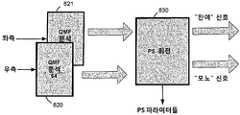
도 8에서, 본 발명의 일 실시예가, 좌측 채널 및 우측 채널용 2개의 QMF 분석 필터뱅크들(820, 821), 회전 모듈(830), QMF 영역과 대응하는 회전 파라미터들에서 2개의 입력 신호들로부터 2개의 새로운 신호들을 재생성하는, 소위 파라메트릭 스테레오(PS) 모듈을 추가함으로써, 스테레오로 확장되어 있다. 이 2개의 새로운 신호들은 모노 다운믹스 신호 및 잔여 신호를 나타낸다. 이들은 좌측/우측 스테레오 신호들의 미드/사이드(Mid/Side) 변환으로서 가시화될 수 있는데, 여기에서 미드/사이트 스테레오 공간은 미드 신호(즉, 다운믹스 신호)에서의 에너지가 최대화되고, 사이드 신호(즉, 잔여 신호)에서의 에너지가 최소화되도록 회전된다. 특정 실시예로서, 좌측 또는 우측으로 45도 패닝된(panned) 모노 소스는 좌측 채널 또는 우측 채널 모두에서 (서로 다른 레벨로) 나타난다. 종래 파형 오디오 코더는 좌측 채널 및 우측 채널을 독립적으로 코딩할 지 또는 미드/사이드 표현으로서 코딩할 지를 선택한다. 이 특정 실시예에서, 패닝된(panned) 모노 소스는 상기 표현을 무시한 양 채널들에 나타나므로, 좌측/우측 표현도, 미드/사이드 표현도 이익이 아니다. 그러나, 만약 미드/사이드 표현이 45도 회전된다면, 패닝된 모노 소스는 회전된 미드 채널(여기에서, 다운믹스 채널이라고 함)에서 완전히 끝나며, 회전된 사이드 채널(여기에서, 잔여 채널이라고 함)이 0이 된다. 이는 보통의 좌측/우측 또는 미드/크기 코딩에 대해 코딩 장점을 제공한다.In FIG. 8, an embodiment of the present invention provides two input signals in two
추출된 파라미터들과의 조합으로 스테레오 신호를 나타내는, 2개의 새로운 신호들은 이어서, 도 7에 도시된 바와 같이, 예컨대, QMF 합성 모듈들 및 SBR 모듈들로 입력된다. 낮은 비트레이트에 대해, 잔여 신호는 저역-통과 필터링되거나 완전하게 제거될 수 있다. 파라메트릭 스테레오 디코더는 제거된 잔여 신호를 다운믹스 신호의 비상관된 버전으로 대체한다. 물론, 스테레오 신호에 관한 이 제안된 처리는 본 발명의 다른 실시예와 역시 결합될 수 있다.Two new signals, representing the stereo signal in combination with the extracted parameters, are then input to, for example, QMF synthesis modules and SBR modules, as shown in FIG. 7. For low bitrates, the residual signal can be lowpass filtered or completely removed. The parametric stereo decoder replaces the removed residual signal with an uncorrelated version of the downmix signal. Of course, this proposed process for stereo signals can also be combined with other embodiments of the present invention.
더 상세하게, PS 모듈은 대응하는 시간/주파수 타일들(tiles)에 대해 2개의 입력 신호들(좌측 및 우측)을 비교한다. 타일들의 주파수 대역들은 심리음향적으로 자극받을 스케일에 근사화하도록 설계되는 반면, 세그먼트들의 길이는 바이노럴 청취 시스템의 공지된 한계점들에 가깝게 매칭된다. 필수적으로, 지각적으로 매우 중요한 아래의 공간적 특성들을 나타내는, 3개의 파라미터들이 시간/주파수 타일마다 추출된다:More specifically, the PS module compares two input signals (left and right) against corresponding time / frequency tiles. The frequency bands of the tiles are designed to approximate the psychoacoustic stimulus scale, while the lengths of the segments closely match the known limits of the binaural listening system. Essentially, three parameters are extracted per time / frequency tile, representing perceptually important spatial characteristics below:
(i) 혼합 콘솔(mixing console) 상의 "팬 포트(pan pot)"와 유사하게, 채널들 간의 레벨차를 나타내는 ILD(Inter-channel Level Difference).(i) Inter-channel Level Difference (ILD) indicating the level difference between channels, similar to a "pan pot" on a mixing console.
(ii) 채널들 간의 위상차를 나타내는 IPD(Inter-channel Phase Difference). 주파수 영역에서 이 특성은 ITD(Inter-channel Time Difference)와 거의 서로 교환가능하다. IPD는 추가적인 OPD(Overall Phase Difference)만큼 증가되어, 좌측 및 우측 위상 조정의 분배를 설명한다.(ii) Inter-channel Phase Difference (IPD) indicating phase difference between channels. In the frequency domain, this characteristic is almost interchangeable with ITD (Inter-channel Time Difference). The IPD is increased by an additional overall phase difference (OPD) to account for the distribution of left and right phase adjustments.
(iii) 채널 사이의 코히어런스 또는 상호-상관을 나타내는 IC(Inter-channel Coherence). 첫번째 2개의 파라미터들은 사운드 소스들의 방향으로 결합되고, 세번째 파라미터는 소스의 공간적 발산과 더 관련된다.(iii) Inter-channel Coherence (IC) indicating coherence or cross-correlation between channels. The first two parameters are combined in the direction of the sound sources and the third parameter is further related to the spatial divergence of the source.
파라미터들의 추출 이후에는, 입력 신호들이 모노 신호를 형성하도록 다운믹스된다. 다운믹스는 평범한 수단의 합산 프로세스에 의해 이루어질 수 있지만, 다운믹스에서 잠재적인 위상 상쇄를 피하기 위해 시간 정렬과 에너지 보존 기술들을 통합하는 바람직하게 더 개선된 방법들이 결합된다. 디코더측에서, 대응하는 인코더의 역의 프로세스를 기본적으로 포함하며, PS 파라미터들에 기초하여 스테레오 출력 신호들을 재구성하는 PS 디코딩 모듈이 제공된다.After extraction of the parameters, the input signals are downmixed to form a mono signal. The downmix can be accomplished by a summation process by ordinary means, but preferably more advanced methods are incorporated that incorporate time alignment and energy conservation techniques to avoid potential phase cancellation in the downmix. At the decoder side, a PS decoding module is provided, which basically includes the inverse process of the corresponding encoder, and reconstructs stereo output signals based on the PS parameters.
도 9에서, 본 발명의 다른 실시예가 도시되어 있다. 여기에서, 입력 신호는 64 서브밴드 채널 QMF 모듈(920)에 의해 다시 분석된다. 그러나, 도 7에 도시된 시스템과는 반대로, 코어 코더 및 SBR 코더에 의해 커버되는 범위 사이의 경계는 가변적이다. 그에 따라, 시스템은 시간-영역 신호의 대역폭을 커버하기 위해, 추후 LPC, MDCT 및 LTP 모듈(901)에 의해 코딩될, 필요한 만큼 많은 서브밴드들을 모듈(911)에서 합성한다. 나머지(주파수에서 더 높은) 서브밴드 샘플들은 SBR 인코더(912)에 입력된다.In Fig. 9, another embodiment of the present invention is shown. Here, the input signal is analyzed again by the 64 subband
전술한 실시예들에 추가하여, 높은 서브밴드 샘플들은 더 높은 주파수 범위를 저역-통과 신호로 합성하는 QMF 합성 모듈(920)로 또한 입력될 수 있으며, 그에 따라 다운-변조된 고주파수 범위를 포함한다. 그런 다음, 이 신호는 추가적인 MDCT-기반 MDCT-기반 코더(930)에 의해 코딩된다. 추가적인 MDCT-기반 MDCT-기반 코더(930)로부터의 출력은 선택적인 결합 유닛(940)에서 SBR 인코더 출력과 결합될 수 있다. 어떤 부분이 SBR로 코딩되는지를, 그리고 어떤 부분이 MDCT-기반 파형 코더로 코딩되는지를 나타내는 시그널링이 생성되어 디코더로 전송된다. 이는 SBR 코딩으로부터 파형 코딩으로의 평탄한 전이를 가능하게 한다. 또한, 이들은 개별적인 MDCT 변환들로 코딩되기 때문에, 저주파수들 및 고주파수들에 대해 MDCT 코딩에서 사용되는 변환 크기에 관련한 선택의 자유가 가능하게 된다.In addition to the above embodiments, high subband samples may also be input to
도 10에서 다른 실시예가 도시되어 있다. 입력 신호는 QMF 분석 모듈(1010)로 입력된다. SBR 범위에 대응하는 출력 서브밴드들은 SBR 인코더(1012)로 입력된다. LPC 분석 및 필터링은 신호의 전체 주파수 범위를 커버함으로써 이루어지며, 입력 신호를 직접적으로 사용하거나 QMF 합성 모듈(1011)에 의해 생성된 QMF 서브밴드 신호의 합성된 버전을 사용함으로써 이루어진다. 후자는 도 8의 스테레오 구현과 결합될 때 유용한다. LPC 필터링된 신호는 코딩될 스펙트럼 라인들을 제공하는 MDCT 분석 모듈(1002)로 입력된다. 본 발명의 일 실시예에서, 양자화(1003)는 상당히 더 조악한 양자화가 SBR 영역(즉, SBR 인코더에 의해서 또한 커버되는 주파수 영역)에서 발생하도록 실행되어 가장 강한 스펙트럼 라인들만을 커버한다. 양자화된 스펙트럼 및 SBR 인코딩된 데이터가 주어지면, SBR 범위에서 서로 다른 주파수 범위들을 위해 사용할 신호가 무엇인지 즉, SBR 데이터인지 또는 파형 코딩된 데이터인지를 디코더로 시그널링하는 것을 제공하는 정보가 결합 유닛(1040)으로 입력된다.Another embodiment is shown in FIG. 10. The input signal is input to the
도 11에서는, 본 발명의 코딩 시스템의 매우 일반적인 도해가 설명된다. 실시예적인 인코더는 입력 신호를 취하고, 다른 데이터:In Figure 11 a very general illustration of the coding system of the present invention is described. An exemplary encoder takes an input signal and other data:
ㆍ 양자화된 MDCT 라인들;Quantized MDCT lines;
ㆍ 스케일인자들;Scale factors;
ㆍ LPC 다항식 표현;LPC polynomial representation;
ㆍ 신호 세그먼트 에너지(예를 들어, 신호 변동);Signal segment energy (eg signal variation);
ㆍ 윈도우 시퀀스;Window sequence;
ㆍ LTP 데이터;LTP data;
중의 데이터를 포함하는 비트스트림을 생성한다.Generates a bitstream that contains the data.
본 발명에 따르는 디코더는 제공된 비트스트림을 읽고 심리-음향적으로 원래 신호와 유사한 오디오 출력 신호를 생성한다.The decoder according to the invention reads the provided bitstream and generates an audio output signal which is psycho-acoustically similar to the original signal.
도 11a는 본 발명의 일 실시예에 따른 인코더(1100) 측면들의 다른 예이다. 인코더(1100)는 LPC 모듈(1101), MDCT 모듈(1104), LTP 모듈(1105)(간략하게만 도시됨), 양자화 모듈(1103), 및 재구성된 신호를 LTP 모듈(1105)로 궤환시키는 역 양자화 모듈(1104)을 포함한다. 추가적으로 입력 신호의 피치를 추산하는 피치 추산 모듈(1150), 및 입력 신호의 더 큰 블록에 대한 최적의 MDCT 윈도우 시퀀스(예를 들어, 1 초)를 결정하는 윈도우 시퀀스 결정 모듈(1151)을 포함한다. 이 실시예에서, MDCT 윈도우 시퀀스는, 코딩 비용 함수, 예를 들어 단순화된 지각적 엔트로피를 최소화시키도록 MDCT 윈도우 크기 후보들의 시퀀스가 결정되는 오픈-루프 접근에 기초하여 결정된다. 최적의 MDCT 윈도우 시퀀스를 검색할 때 윈도우 시퀀스 결정 모듈(1151)에 의해 최소화되는 코딩 비용 함수에 대한 LTP 모듈(1105)의 기여분이 선택적으로 고려될 수 있다. 바람직하게는, 각 평가된 윈도우 크기 후보에 대해, 윈도우 크기 후보에 대응되는 MDCT 프레임에 대한 최상의 장기 예측 기여분이 결정되고, 개별적인 코딩 비용이 추산된다. 일반적으로, 짧은 MDCT 프레임 크기들은 음성 입력에 대해 보다 적절하고 미세한 스펙트럼 해상도를 가지는 긴 변환 윈도우들은 오디오 신호에 대해 바람직하다.11A is another example of aspects of an
지각적 가중치들 또는 지각적 가중 함수가, LPC 모듈(1101)에 의해 계산되는 바와 같은 LPC 파라미터들에 기초하여 결정되는데, 아래에서 보다 자세히 설명될 것이다. 지각적 가중치들은, 모두 MDCT-영역에서 동작하고 개별적인 지각적 중요성에 따른 주파수 성분들의 왜곡 기여분 또는 에러를 가중하는 LTP 모듈(1105) 및 양자화 모듈(1103)에 공급된다. 도 11a는 또한 어떤 코딩 파라미터들이, 바람직하게는 이후에 설명되는 바와 같은 적절한 코딩 방안에 의해 디코더로 전송되는지 도시한다.Perceptual weights or perceptual weighting function are determined based on LPC parameters as calculated by the
다음으로, LPC 및 MDCT 데이터의 병존 및 MDCT에서의 LPC 효과의 에뮬레이션이, 반작용 및 실질적인 필터링 생략 양쪽을 위해 설명될 것이다.Next, the coexistence of LPC and MDCT data and the emulation of LPC effects in MDCT will be described for both reaction and substantial filtering omission.
일 실시예에 따르면, LP 모듈이 신호의 스펙트럼 형상이 제거되도록 입력 신호를 필터링하고, LP 모듈의 후속하는 출력은 스펙트럼적으로 평평한 신호이다. 이것은 예를 들어, LTP 동작에 유리하다. 하지만, 스펙트럼적으로 평평한 신호 상에서 동작하는 코덱의 다른 부분들은 원래 신호의 스펙트럼 형상이 LP 필터링 이전에 무엇이었는지 아는 것으로부터 이득을 얻을 수 있다. 필터링 이후에, 인코더 모듈이 스펙트럼적으로 평평한 신호의 MDCT 변환 상에서 동작하기 때문에, 본 발명은 LP 필터링 이전의 원래 신호의 스펙트럼 형상이, 필요하다면, 사용된 LP 필터(즉, 원래 신호의 스펙트럼 포락선)의 전달 함수를 이득 커브, 혹은, 스펙트럼적으로 평평한 신호의 MDCT 표현의 주파수 빈들 상에 적용되는 등화 커브로 매핑시킴으로써, 스펙트럼적으로 평평한 신호의 MDCT 표현 상에서 재-도입될 수 있음을 시사한다. 반대로, LP 모듈은 실질적인 필터링을 생략하고, 신호의 MDCT 표현 상에 도입될 수 있는 이득 커브에 연속적으로 매핑되는 전달 함수를 단지 추산하여, 입력 신호의 시간 영역 필터링의 필요성을 제거할 수 있다.According to one embodiment, the LP module filters the input signal such that the spectral shape of the signal is removed, and the subsequent output of the LP module is a spectrally flat signal. This is for example advantageous for LTP operation. However, other parts of the codec operating on a spectrally flat signal may benefit from knowing what the spectral shape of the original signal was prior to LP filtering. Since after the filtering, the encoder module operates on the MDCT transform of the spectrally flat signal, the present invention provides the spectral shape of the original signal before LP filtering, if necessary, the LP filter used (ie the spectral envelope of the original signal). By mapping the transfer function of to a gain curve, or an equalization curve applied on the frequency bins of the MDCT representation of the spectrally flat signal, it can be re-introduced on the MDCT representation of the spectrally flat signal. In contrast, the LP module can omit substantial filtering and only estimate the transfer function that is continuously mapped to the gain curve that can be introduced on the MDCT representation of the signal, thus eliminating the need for time domain filtering of the input signal.
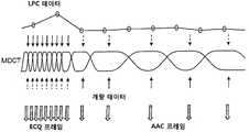
본 발명의 실시예들의 중요한 측면 하나는 MDCT-기반 변환 코더가 유연한 윈도우 세그멘트화를 사용해 LPC 백색화된 신호 상에서 동작된다는 점이다. 이것이, 실시예적인 MDCT 윈도우 시퀀스가 LPC의 윈도우잉과 더불어 주어진 도 12에 도시되어 있다. 따라서, 도면으로부터 명백한 바와 같이, LPC는 일정한 프레임-크기(예를 들어, 20ms) 상에서 동작하며, MDCT는 가변 윈도우 시퀀스(예를 들어, 4 내지 128ms) 상에서 동작한다. 이것이 LPC에 대한 최적의 윈도우 길이 및 MDCT에 대한 최적의 윈도우 시퀀스를 독립적으로 선택할 수 있도록 한다.One important aspect of embodiments of the present invention is that the MDCT-based transform coder is operated on LPC whitened signals using flexible window segmentation. This is shown in FIG. 12, where an exemplary MDCT window sequence is given along with windowing of the LPC. Thus, as is apparent from the figure, the LPC operates on a constant frame-size (eg, 20 ms) and the MDCT operates on a variable window sequence (eg, 4 to 128 ms). This makes it possible to independently select the optimal window length for the LPC and the optimal window sequence for the MDCT.
도 12는 추가적으로 LPC 데이터, 특히 제1 프레임 레이트로 생성된 LPC 파라미터들과 MDCT 데이터, 특히 제2 가변 레이트로 생성된 MDCT 라인들 사이의 관계를 도시한다. 도면에서 아래쪽으로 향하는 화살표들은 해당하는 MDCT 프레임들을 매칭시키기 위해 LPC 프레임들(원들) 사이에서 보간된 LPC 데이터를 심볼화한다. 예를 들어, LPC-생성된 지각적 가중 함수가 MDCT 윈도우 시퀀스에 의해 결정된 바와 같은 시간 인스턴스에 대해 보간된다. 위쪽으로 향하는 화살표들은 MDCT 라인들 코딩을 위해 사용된 정제 데이터(refinement data)(즉, 제어 데이터)를 심볼화한다. AAC 프레임에 대해서는 이러한 데이터가 통상적으로 스케일인자이며, ECQ 프레임에 대해서는 데이터가 통상적으로 변동 보정 데이터 등이다. 점선에 대비해 실선 라인들은 특정 양자화기가 주어진 상태에서 MDCT 라인들 코딩에 대해 어떤 데이터가 가장 "중요한" 데이터인지 나타낸다. 아래쪽으로 향하는 이중 화살표는 코덱 스펙트럼 라인들을 심볼화한다.12 further shows the relationship between LPC data, in particular LPC parameters generated at a first frame rate, and MDCT data, in particular MDCT lines, generated at a second variable rate. Downward arrows in the figure symbolize interpolated LPC data between LPC frames (circles) to match corresponding MDCT frames. For example, LPC-generated perceptual weighting functions are interpolated over time instances as determined by the MDCT window sequence. The upward pointing arrows symbolize refinement data (ie, control data) used for coding the MDCT lines. For an AAC frame, such data is typically a scale factor, and for an ECQ frame, the data is typically variation correction data or the like. Solid lines against dashed lines indicate which data is the most "important" data for coding MDCT lines with a particular quantizer given. The downward double arrow symbolizes the codec spectral lines.
인코더에서 LPC 및 MDCT 데이터의 병존은 예를 들어, LPC 파라미터로부터 추산된 지각적 마스킹 커브를 고려함으로써 MDCT 스케일인자를 인코딩하는 데 필요한 비트를 감소시키는 데 이용될 수 있다. 또한, LPC 도출된 지각적 가중화가 양자화 왜곡을 결정할 때 사용될 수 있다. 도시된 바와 같이, 그리고 아래에서 설명되는 바와 같이, 양자화기는 두 개의 모드로 동작하고 수신된 데이터의 프레임 크기에 기초하여, 즉 MDCT 프레임 또는 윈도우 크기에 상응하여 두 종류의 프레임(ECQ 프레임 및 AAC 프레임)을 생성한다.The coexistence of LPC and MDCT data in the encoder can be used to reduce the bits required to encode the MDCT scale factor, for example by taking into account the perceptual masking curves estimated from the LPC parameters. In addition, LPC derived perceptual weighting can be used when determining quantization distortion. As shown and as described below, the quantizer operates in two modes and is based on the frame size of the received data, i.e. corresponding to the MDCT frame or window size, two types of frames (ECQ frame and AAC frame). ).
도 15는 고정 레이트 LPC 파라미터를 적응적 MDCT 윈도우 시퀀스 데이터로 매핑하는 바람직한 일 실시예를 도시한다. LPC 매핑 모듈(1500)은 LPC 업데이트 레이트에 따라 LPC 파라미터를 수신한다. 또한, LPC 매핑 모듈(1500)은 MDCT 윈도우 시퀀스에 대한 정보를 수신한다. 그리고, 예를 들어, LPC-기반 심리-음향적 데이터를 가변 MDCT 프레임 레이트로 생성된 개별적인 MDCT 프레임들로 매핑시키기 위해, LPC-대-MDCT 매핑을 생성한다. 예를 들어, LPC 매핑 모듈은, 예를 들어, LPC 모듈 또는 양자화기에서의 지각적 가중치로서의 사용을 위한 MDCT 프레임들에 상응하는 시간 인스턴스에 대해 관련 데이터 또는 LPC 다항식을 보간한다.15 illustrates one preferred embodiment for mapping fixed rate LPC parameters to adaptive MDCT window sequence data. The
이제, LPC-기반 지각적 모델의 상세사항들이 도 13을 참조하여 논의된다. LPC 모듈(1301)은, 본 발명의 일 실시예에서, 예를 들어, 16 kHz 샘플링 레이트 신호에 대해 차수(order) 16의 선형 예측을 이용해 백색 출력 신호를 생성하도록 조정된다. 예를 들어, 도 2의 LPC 모듈(201)로부터의 출력은 LPC 파라미터 추산 및 필터링 이후의 잔여물이다. 도 13의 좌측 하단에 도식적으로 형상화된 바와 같이, 추산된 LPC 다항식 A(z)는 대역폭 확장 인자에 의해 처프(chirp)될 수 있고, 또한, 본 발명의 일 구현예에서, 상응하는 LPC 다항식의 제1 반사 계수를 변형함으로써 틸트(tilt)될 수 있다. 처핑(chirping)은 다항식의 극들을 단위 원 내부 방향으로 이동시킴으로써 LPC 전달 함수의 피크들의 대역폭을 확장시키고, 따라서, 보다 부드러운 피크들을 도출한다. 틸팅(tilting)은 더 낮은 그리고 더 높은 대역들의 영향을 밸런스시키기 위해 LPC 변환 함수 플래터(flatter)를 형성하도록 한다. 이러한 변형들은 시스템의 인코더 및 디코더 양측에서 유효하게 될 추산된 LPC 파라미터들로부터 지각적 마스킹 커브 A'(z)를 생성하도록 노력한다. 도 16에 나타난 LPC 다항식의 조작에 관한 상세사항들이 아래에서 소개된다.Details of the LPC-based perceptual model are now discussed with reference to FIG. 13. The
LPC 잔여물에 대해 동작하는 MDCT 코딩은, 본 발명의 일 구현예에서, 양자화기 또는 양자화기 스텝 크기들(그리고, 그에 따라, 양자화에 의해 나타나는 노이즈)의 해상도를 조절하기 위한 스케일인자들을 갖는다. 이러한 스케일인자들은 원래 입력 신호에 대해 스케일인자 추산 모듈(1360)에 의해 추산된다. 예를 들어, 스케일인자들은 원래 신호로부터 추산된 지각적 마스킹 임계 커브로부터 도출된다. 일 실시예에서, 개별적 주파수 변환(가능하게는 다른 주파수 해상도를 가지는)이 마스킹 임계 커브를 결정하는 데 사용될 수 있는데, 그렇다고 이것이 항상 필수적인 것은 아니다. 대안적으로, 마스킹 임계 커브가 변환 모듈에 의해 생성된 MDCT 라인들로부터 추산된다. 도 13의 우측 하단부는, 양자화를 제어하여 도입된 양자화 노이즈가 불가청(inaudible) 왜곡으로 제한되도록 하는 스케일인자 추산 모듈(1360)에 의해 생성된 스케일인자들을 도해적으로 도시한다.MDCT coding operating on LPC residues, in one embodiment of the invention, has scale factors for adjusting the resolution of the quantizer or quantizer step sizes (and hence the noise exhibited by quantization). These scale factors are estimated by the scale
LPC 필터가 MDCT 변환 모듈의 업스트림에 연결된 경우, 백색화된 신호가 MDCT-영역으로 변환된다. 이 신호가 백색 스펙트럼을 가지므로, 그로부터 지각적 마스킹 커브를 도출하기에 그리 적합하지 않다. 따라서, 마스킹 임계 커브 및/또는 스케일인자들을 추산할 때 스펙트럼의 백색화를 보상하기 위해 생성된 MDCT-영역 양자화 이득 커브가 사용될 수 있다. 이것은, 지각적 마스킹을 올바로 추산하기 위해, 스케일인자들이 원래 신호의 절대적인 스펙트럼 특성들을 가지는 신호 상에서 추산되어야 하기 때문이다. LPC 다항식으로부터 MDCT 영역 양자화 이득 커브를 계산하는 것이 도 14와 관련하여 아래에서 보다 자세히 논의될 것이다.When the LPC filter is connected upstream of the MDCT transform module, the whitened signal is transformed into the MDCT region. Since this signal has a white spectrum, it is not very suitable for deriving a perceptual masking curve from it. Thus, the generated MDCT-region quantization gain curve can be used to compensate for the whitening of the spectrum when estimating masking threshold curves and / or scale factors. This is because in order to correctly estimate perceptual masking, the scale factors must be estimated on a signal that has the absolute spectral characteristics of the original signal. Computing the MDCT region quantization gain curve from the LPC polynomial will be discussed in more detail below with respect to FIG. 14.
상술한 접근 방법을 사용해, 인코더 및 디코더 간에 전송되는 데이터는, 모델-기반 양자화기가 사용되는 경우 신호 모델뿐 아니라 관련 지각적 정보 또한 도출될 수 있는 LP 다항식, 그리고 변환 코덱에서 통상적으로 사용되는 스케일인자들을 모두 포함한다.Using the approach described above, the data transmitted between the encoder and decoder is an LP polynomial that can derive not only the signal model but also relevant perceptual information when a model-based quantizer is used, and scale factors commonly used in transform codecs. Include them all.
보다 상세하게는, 도 13으로 다시 돌아가, 도면의 LPC 모듈(1301)은 입력 신호로부터 신호의 스펙트럼 포락선 A(z)를 추산하고 이로부터 지각적 표현 A'(z)를 도출한다. 뿐만 아니라, 변환 기반 지각적 오디오 코덱에서 일반적으로 사용되는 스케일인자들이 입력 신호 상에서 추산되거나, 혹은, LP 필터의 전달 함수가 스케일인자 추산에서 고려되는 경우(아래의 도 14의 문맥에서 서술되는 바와 같이), LP 필터에 의해 생성된 백색 신호 상에서 추산될 수 있다. 스케일인자들은 그리고 나서, 아래에서 설명되는 바와 같이, 스케일인자들을 전송하는 데 필요한 비트 레이트를 줄이기 위해, LP 다항식이 주어진 스케일인자 조정 모듈(1361)에서 조정될 수 있다.More specifically, returning back to FIG. 13, the
일반적으로, 스케일인자들은 디코더 측으로 전송되고, LP 다항식도 마찬가지이다. 이제, 이들이 모두 원래 입력 신호로부터 추산되고, 원래 입력 신호의 절대적 스펙트럼 특성들에 어느 정도 상관되어 있다고 한다면, 이 둘이 개별적으로 전송되는 경우 발생할 수 있는 어떤 잉여물이라도 제거하기 위해, 이들 사이의 델타 표현을 코딩할 것이 제안된다. 일 실시예에 따르면, 이러한 상관성은 아래와 같이 이용된다. LPC 다항식이, 올바로 처프되고 틸트될 때, 마스킹 임계 커브를 나타내기 위해 노력하기 때문에, 변환 코더의 전송된 스케일인자들이 원하는 스케일인자들 및 전송된 LPC 다항식으로부터 도출될 수 있는 것들과의 차이를 나타내도록 두 표현들이 결합될 수 있다. 도 13에 도시된 스케일인자 조정 모듈(1361)은 그러므로 원래 입력 신호로부터 생성된 원하는 스케일인자들 및 LPC-도출된 스케일인자들 간의 차이를 연산한다. 이러한 측면은, LPC 구조 내에서, LPC 잔여물에 대해 동작하는 변환 코더에서 통상적으로 사용되는 스케일인자들의 개념을 가지는 MDCT-기반 양자화기를 갖는 능력을 유지하고, 또한 여전히 선형 예측 데이터로부터 단독으로 양자화 스텝 크기들을 도출하는 모델-기반 양자화기로 전환할 가능성을 가진다.In general, scale factors are sent to the decoder side, and so is the LP polynomial. Now, if they are all estimated from the original input signal and somewhat correlated to the absolute spectral characteristics of the original input signal, the delta representation between them is removed to remove any surpluses that may occur if they are transmitted separately. It is proposed to code. According to one embodiment, this correlation is used as follows. Since the LPC polynomial tries to represent the masking threshold curve when properly chirped and tilted, the transmitted scale factors of the transform coder show differences between the desired scale factors and those that can be derived from the transmitted LPC polynomials. The two expressions can be combined. The scale
도 14는 LPC 다항식들을 MDCT 이득 커브로 변환하는 바람직한 일 실시예를 도시한다. 도 2에 도시된 바와 같이, MDCT는 LPC 필터(1401)에 의해 백색화된, 백색화된 신호 상에서 동작한다. 원래 입력 신호의 스펙트럼 포락선을 유지하기 위해서는, MDCT 이득 커브가 MDCT 이득 커브 모듈(1470)에 의해 연산된다. MDCT-영역 등화 이득 커브는 MDCT 변환에서의 빈들에 의해 표현되는 주파수들에 대해, LPC 필터에 의해 서술된 스펙트럼 포락선의 크기 응답을 추산함으로써 획득될 수 있다. 이득 커브는 그리고 나서, 예를 들어, 도 3에 도시된 바와 같이 최소평균제곱에러를 계산할 때, 혹은 위에서 도 13을 참조로 하여 설명된 바와 같은 스케일인자 결정을 위한 지각적 마스킹 커브를 추산할 때, MDCT 데이터 상에 적용될 수 있다.Figure 14 illustrates one preferred embodiment for converting LPC polynomials to MDCT gain curves. As shown in FIG. 2, MDCT operates on a whitened signal, whitened by an
도 16은 변환 크기 및/또는 양자화기의 유형에 기초하여 지각적 가중 필터 연산을 조정하는 바람직한 일 실시예를 도시한다. LP 다항식 A(z)는 도 16의 LPC 모듈(1601)에 의해 추산된다. LPC 파라미터 변형 모듈(1271)은, LPC 다항식 A(z)와 같은, LPC 파라미터들을 수신하고, LPC 파라미터들을 변형함으로써 지각적 가중 필터 A'(z)를 생성한다. 예를 들어, LPC 다항식 A(z)의 대역폭이 확장되거나 및/또는 다항식이 틸트된다. 처프 & 틸트 조정 모듈(1672)에 대한 입력 파라미터들은 기본적인 처프 및 틸크 값들


아래에서는, 본 발명의 일 실시예에 따른 프레임-크기에 대해 맞춰진 양자화 정책, 및 정리된 파라미터들에 대해 맞춰진 모델-기반 양자화가 설명될 것이다. 본 발명의 일 측면은 여러 변환 크기들 또는 프레임 크기들에 대해 다른 양자화 정책들을 사용하는 것이다. 이것이 도 17에 도시되어 있는데, 여기서는 프레임 크기가 모델-기반 양자화기 또는 비-모델-기반 양자화기를 사용하기 위한 선택 파라미터로서 사용된다. 이러한 양자화 측면은 개시된 인코더/디코더의 다른 측면들과는 독립적이고, 다른 코텍들에서도 마찬가지로 적용될 수 있음이 주지되어야 할 것이다. 비-모델-기반 양자화기의 일 실시예가 AAC 오디오 코딩 기준에서 사용되는 허프만 테이블 기반 양자화기이다. 모델-기반 양자화기는 산술적 코딩을 적용한 엔트로피 제한 양자화기(ECQ)가 될 수 있다. 하지만, 다른 양자화기들 또한 본 발명의 실시예들에서 사용될 수 있다. 또한, 본 발명의 현재 설명되는 실시예에서, 양자화기의 선택은 변환 크기에 의해 내재적으로 디코더로 시그널링된다. 어떤 양자화 전략이 특정 프레임-크기를 위해 사용되었는 지에 관한 정보를 디코더로 명백하게 전송하는 것과 같은 다른 방식의 시그널링이 또한 사용될 수 있음이 명백하다.In the following, a quantization policy tailored to the frame-size and a model-based quantization tailored to the summarized parameters will be described according to one embodiment of the invention. One aspect of the present invention is to use different quantization policies for various transform sizes or frame sizes. This is shown in FIG. 17, where the frame size is used as a selection parameter for using a model-based quantizer or a non-model-based quantizer. It should be noted that this quantization aspect is independent of other aspects of the disclosed encoder / decoder, and may be applied to other codecs as well. One embodiment of a non-model-based quantizer is a Huffman table based quantizer used in AAC audio coding criteria. The model-based quantizer can be an entropy limited quantizer (ECQ) with arithmetic coding. However, other quantizers can also be used in embodiments of the present invention. In addition, in the presently described embodiment of the present invention, the selection of the quantizer is implicitly signaled to the decoder by the transform size. It is clear that other manners of signaling may also be used, such as explicitly sending information to the decoder about which quantization strategy was used for a particular frame-size.
본 발명의 독립적인 일 측면에 따르면, 특정 프레임 크기가 주어진 최적의 양자화 정책을 사용 가능하도록 하기 위해 프레임 크기의 함수로서 여러 양자화 정책들 간의 전환이 제안된다. 일 실시예로서, 윈도우-시퀀스가 신호의 매우 고정적인 색조의(tonal) 음악 세그먼트에 대해 장기 변환의 사용을 유도할 수 있다. 장기 변환을 사용하는 이러한 특정 신호 유형에 대해서는, 신호의 스펙트럼에서 "희박한" 캐릭터(즉, 잘 정의된 이산 톤들)를 활용할 수 있는 양자화 정책을 채용하는 것이 매우 유리하다. 허프만 테이블과 결합하여 AAC에서 사용된 바와 같은 양자화 방법 및 또한, AAC에서 사용된 바와 같은 스펙트럼 라인들의 그룹화가 매우 유리하다. 하지만, 그리고, 반대로 음성 세그먼트에 대해, 윈도우-시퀀스가 LTP의 코딩 이득이 주어진 상태에서 단기 변환의 사용을 유도할 수 있다. 이러한 신호 유형 및 변환 크기에 대해 스펙트럼에서 희박성을 탐색하거나 소개하고자 노력하지 않고, 그 대신, LTP가 주어진 상태에서 원래 입력 신호의 펄스 유사 특성을 유지할 것인 광대역 에너지를 유지하는 양자화 정책을 채용하는 것이 유리하다.According to an independent aspect of the present invention, a switch between several quantization policies is proposed as a function of frame size to enable an optimal quantization policy given a particular frame size. In one embodiment, the window-sequence may lead to the use of long-term transforms for highly fixed tonal music segments of the signal. For this particular signal type using a long term transform, it is very advantageous to employ a quantization policy that can utilize "lean" characters (ie, well defined discrete tones) in the spectrum of the signal. The quantization method as used in AAC in combination with the Huffman table and also the grouping of spectral lines as used in AAC is very advantageous. However, and vice versa, for speech segments, the window-sequence can lead to the use of short-term transforms given the coding gain of LTP. Instead of trying to explore or introduce sparsity in the spectrum for these signal types and transform magnitudes, instead, employing a quantization policy that maintains broadband energy that will maintain the pulse-like properties of the original input signal in a given state of LTP. It is advantageous.
이러한 개념의 보다 일반적인 형상화가 도 18에서 주어지는데, 여기서 입력 신호는 MDCT-영역으로 변환되고, 이어 변환 크기 또는 MDCT 변환에 사용되는 프레임 크기에 의해 제어되는 양자화기에 의해 양자화된다.A more general shaping of this concept is given in FIG. 18, where the input signal is transformed into an MDCT-domain and then quantized by a quantizer controlled by the transform size or frame size used for the MDCT transform.
본 발명의 다른 측면에 따르면, 양자화 스텝 크기가 LPC 및/또는 LPC 데이터의 함수로서 조정된다. 이것은 프레임의 난이도에 따라 스텝 크기를 결정하도록 하고 프레임을 인코딩하는 데 할당된 비트들의 개수를 제어한다. 도 19에서 모델-기반 양자화가 어떻게 LPC 및 LTP 데이터에 의해 제어될 수 있는지에 대한 설명이 주어진다. 도 19의 상단 부분에서, MDCT 라인들의 도해적 형상화가 주어진다. 아래에서 양자화 스텝 크기 델타
LPC 데이터로부터 도출된 바람직한 지각적 가중 함수가 아래의 식에서 주어진다.The preferred perceptual weighting function derived from the LPC data is given by the equation below.

여기서, A(z)는 LPC 다항식이고,

추가적으로, 델타 값들


아래에서는, 본 발명의 일 실시예에 따른 모델-기반 양자화기가 약술된다. 도 20에서는, 모델-기반 양자화기의 측면들 중 하나가 형상화된다. MDCT 라인들은 균일 스칼라 양자화기를 채용하는 양자화기에 대한 입력이다. 게다가, 랜덤 오프셋들이 양자화기로 입력되고, 간격 경계들을 시프트하는 양자화 간격들에 대한 오프셋 값들로서 사용된다. 제안된 양자화기는 스칼라 양자화기의 검색가능성을 유지하면서도 벡터 양자화 이점들을 제공한다. 양자화기는 여러 오프셋 값들의 세트 상에서 반복하고, 이들에 대해 양자화 에러를 연산한다. 양자화되는 특정 MDCT 라인들에 대한 양자화 왜곡을 최소화하는 오프셋 값(또는 오프셋 값 벡터)이 양자화에 사용된다. 오프셋 값은 그리고 나서 양자화된 MDCT 라인들과 함께 디코더로 전송된다. 랜덤 오프셋의 사용은 역-양자화된 디코딩된 신호에서 노이즈-필터링을 도입하고, 그렇게 함으로써, 양자화된 스펙트럼에서의 스펙트럼 홀을 피한다. 이것은, 그렇지 않으면 많은 MDCT 라인들이, 재구성된 신호의 스펙트럼에서 가청 홀들을 야기할 제로로 양자화되는 낮은 비트 레이트에 대해 특히 중요하다.In the following, a model-based quantizer according to an embodiment of the present invention is outlined. In FIG. 20, one of the sides of the model-based quantizer is shaped. MDCT lines are input to a quantizer employing a uniform scalar quantizer. In addition, random offsets are input to the quantizer and used as offset values for quantization intervals that shift interval boundaries. The proposed quantizer provides vector quantization advantages while maintaining the searchability of the scalar quantizer. The quantizer repeats on several sets of offset values and computes quantization errors for them. An offset value (or offset value vector) that minimizes quantization distortion for the particular MDCT lines to be quantized is used for quantization. The offset value is then sent to the decoder along with the quantized MDCT lines. The use of random offsets introduces noise-filtering in the de-quantized decoded signal, thereby avoiding spectral holes in the quantized spectrum. This is particularly important for low bit rates where many MDCT lines are otherwise quantized to zero which will cause audible holes in the reconstructed signal's spectrum.
도 21은 본 발명의 일 실시예에 따른 모델-기반 MDCT 라인들 양자화기(MBMLQ)를 도해적으로 도시한다. 도 21의 상단은 MBMLQ 인코더(2100)를 나타낸다. MBMLQ 인코더(2100)는 LTP가 시스템 내에 존재하는 경우, MDCT 프레임의 MDCT 라인들 또는 LTP 잔여물의 MDCT 라인들을 입력으로 취한다. MBMLQ는 MDCT 라인들의 통계적 모델들을 채용하고, 소스 코드들은 MDCT 프레임-바이-프레임을 기반으로 한 신호 특성들에 대해 조정되어 비트스트림으로의 효율적인 압축을 이끌어낸다.21 is a graphical illustration of a model-based MDCT lines quantizer (MBMLQ) in accordance with an embodiment of the present invention. The upper part of FIG. 21 shows the
MDCT 라인들의 국지적 이득은 MDCT 라인들의 RMS 값으로서 추산될 수 있고, MDCT 라인들은 MBMLQ 인코더(2100)로 입력되기 전에 이득 정규화 모듈(2120)에서 정규화된다. 국지적 이득은 MDCT 라인들을 정규화시키고, LP 이득 정규화에 대한 보완이다. LP 이득이 보다 큰 시간 스케일 상에서 신호 레벨에서의 변동에 대해 조정한다면, 국지적 이득은 보다 작은 시간 스케일 상의 변동을 조정하며, 전이 사운드 및 음성에서의 온-셋(on-set)의 개선된 품질을 이끌어낸다. 국지적 이득은 고정된 레이트 혹은 가변 레이트 코딩에 의해 인코딩되고 디코더로 전송된다.The local gain of the MDCT lines can be estimated as the RMS value of the MDCT lines, which are normalized in the
레이트 제어 모듈(2110)이 MDCT 프레임을 인코딩하는 데 사용되는 비트의 개수를 제어하기 위해 채용될 수 있다. 레이트 제어 인덱스는 사용되는 비트의 개수를 제어한다. 레이트 제어 인덱스는 노미널(nominal) 양자화기 스텝 크기들의 리스트를 가리킨다. 테이블은 스텝 크기에 대해 내림차순으로 정렬될 수 있다(도 17g 참조).
MBMLQ 인코더는 여러 레이트 제어 인덱스들의 셋트를 사용해 동작되고, 비트 저장소 제어에 의해 주어지는 승인된 비트들의 개수보다 낮은 비트 카운트를 이끌어내는 레이트 제어 인덱스가 프레임을 위해 사용된다. 레이트 제어 인덱스는 천천히 변화하고, 이것은 검색 복잡도를 줄이기 위해 그리고 인덱스를 효과적으로 인코딩하기 위해 이용될 수 있다. 테스팅이 이전의 MDCT 프레임의 인덱스 근처에서 개시되는 경우 테스트되는 인덱스들의 셋트가 감소될 수 있다. 유사하게, 인덱스의 이전 값 근처에서 확률이 최고치인 경우 인덱스의 효과적인 엔트로피 코딩이 얻어질 수 있는데, 예를 들어, 32 개의 스텝 크기들의 리스트에 대해, 레이트 제어 인덱스가 MDCT 프레임 당 평균 2 비트를 사용해 코딩될 수 있다.The MBMLQ encoder is operated using a set of several rate control indices, and a rate control index is used for the frame which results in a bit count lower than the number of approved bits given by the bit store control. The rate control index changes slowly, which can be used to reduce search complexity and to efficiently encode the index. If testing is initiated near the index of the previous MDCT frame, the set of indices tested can be reduced. Similarly, an effective entropy coding of the index can be obtained if the probability is near the previous value of the index, e.g., for a list of 32 step sizes, the rate control index uses an average of 2 bits per MDCT frame. Can be coded.
도 21은 또한, 국지적 이득이 인코더(2100)에서 추산된 경우, MDCT 프레임이 이득 재정규화된 MBMLQ 디코더(2150)를 도해적으로 도시한다.21 also graphically illustrates
도 21a는 모델-기반 엔트로피 제한된 인코더(2140)를 도해적으로 더 상세히 도시한다. 입력 MDCT 라인들은 이들을, 바람직하게 LPC 다항식(polynomial)으로부터 도출된, 지각적인 마스킹 커브의 값들로 나눔으로써 지각적으로 가중되며, 그에 따라 가중된 MDCT 라인 벡터 y = (y1, ..., yN)이 초래된다. 후속하는 코딩의 목적은 지각의 영역에서 양자화 노이즈를 MDCT 라인으로 도입하는 것이다. 디코더에서는, 지각적 가중의 역이 적용되고 지각적 마스킹 커브를 뒤따르는 양자화 노이즈를 도출한다.21A graphically illustrates model-based entropy limited encoder 2140 in more detail. The input MDCT lines are perceptually weighted by dividing them by the values of the perceptual masking curve, preferably derived from the LPC polynomial, so that the weighted MDCT line vector y = (y1 , ..., yN ) is brought about. The purpose of the subsequent coding is to introduce quantization noise into the MDCT line in the perceptual region. At the decoder, the inverse of the perceptual weighting is applied and derives quantization noise following the perceptual masking curve.
랜덤 오프셋들은 조악한 양자화로 인한 스펙트럼 홀을 회피하기 위한 수단으로 양자화기에 관련하여 이미 설명되었다. 스펙트럼 홀을 회피하는 추가적인 방법은 도 22에 도시된 바와 같이, LTP 루프에 SBR 모듈(2212)을 통합하는 것이다.Random offsets have already been described with respect to quantizers as a means to avoid spectral holes due to coarse quantization. An additional way of avoiding spectral holes is to integrate the
도 22에서, SBR 모듈(2212)은 MDCT 영역에서 동작하며, 저주파수들로부터 고주파수들을 재생성한다. 완전한 인코더/디코더 SBR 시스템과는 반대로, LTP 루프에서의 SBR 모듈은 전체 동작이 스펙트럼적으로 평평한 MDCT 영역에서 수행되기 때문에 어떠한 포락선 조정도 필요로 하지 않는다. 고주파수 재구성 모듈을 LTP 루프 상에 위치하는 장점은, 고주파수 재생성된 신호가 양자화 이전에 감산되어 양자화 이후에 가산된다는 점이다. 여기에서, 만약 비트들이 전체 주파수 범위를 코딩하는데 이용가능하면, 양자화기는 원래의 고주파수들이 유지되도록 신호를 인코딩하고(SBR 기여분이 양자화 이전에 감산되고 양자화 이후에 가산되기 때문에), 만약 비트 제약사항들이 너무 엄격하다면, 양자화기는 고주파수들에서 에너지를 생산할 수 없으며, SBR 재생성된 고주파수들은 출력에서 "폴백(fall back)"으로서 가산되어, 고주파수 범위에서 에너지를 보장할 수 있다.In FIG. 22, the
본 발명의 일 실시예에서, LTP 루프에서의 SBR 모듈은 단순한 복사(copy-up)(즉, 저주파수 라인들이 고주파수 라인들로 복사된다) 메커니즘이다. 다른 실시예에서, 고조파 고주파수 재생성 모듈이 사용된다. 고조파 신호에 대해, 저대역 스펙트럼과 고조파적으로 관련된 고주파수 스펙트럼을 생성하는 SBR 모듈이, 양자화 이전에 입력 신호로부터 감산된 고주파수들이 원래의 고주파수들과 잘 일치하여 양자화기로 들어가는 신호의 에너지를 감소시킬 수 있기 때문에 바람직하며, 그에 따라 어떤 비트 레이트 요구사항으로 양자화하는 것이 용이하게 된다. 세번째 실시예에서, LTP 루프에서의 SBR 모듈은 변환 크기 및 그에 따라 내재적으로 신호 특성에 따라 고주파수들을 재생성하는 방식을 적합하게 할 수 있다.In one embodiment of the invention, the SBR module in the LTP loop is a simple copy-up (ie low frequency lines are copied into high frequency lines) mechanism. In another embodiment, a harmonic high frequency regeneration module is used. For harmonic signals, the SBR module, which generates harmonics associated with the low band spectrum, allows the high frequencies subtracted from the input signal prior to quantization to match the original high frequencies to reduce the energy of the signal entering the quantizer. This is desirable because it makes it easy to quantize to any bit rate requirement. In a third embodiment, the SBR module in the LTP loop may suit the scheme of regenerating high frequencies according to the transform size and hence inherently the signal characteristic.
본 발명은 새로운 윈도우 시퀀스 코딩 포맷을 또한 포함한다. 도 23a, b, c에 도시된 바와 같이, 본 발명의 실시예에 따라, MDCT 변환을 위해 사용되는 윈도우들은 다이애딕(dyadic) 크기들을 가지며, 윈도우에서 윈도우로 크기에서 인자 2만큼 변화할 수 있다. 다이애딕 변환 크기들은 16 kHz 샘플링 레이트에서 4, 8, ..., 128 ms에 대응하는 예컨대, 64, 128, ..., 2048 샘플들이다. 일반적으로 최소 윈도우 크기와 최대 윈도우 크기 사이에서 복수개의 윈도우 크기들을 취할 수 있는 가변 크기 윈도우들이 제안된다. 시퀀스에서, 연속하는 윈도우 크기들은, 갑작스런 변화 없이 윈도우 크기들의 완만한 시퀀스들이 전개되도록, 2의 인자만큼만 변화할 수 있다. 일 실시예에 의해 규정된 바와 같이 즉, 다이애딕 크기들에 한정되며 윈도우에서 윈도우로 크기에서 인자 2만큼 변화하도록 허여된 윈도우 시퀀스들은 몇 가지 장점들을 갖는다. 첫번째로, 특정한 시작 또는 종료 윈도우들 즉, 급격한 에지를 갖는 윈도우들도 필요하지 않는다. 이는 양호한 시간/주파수 해상도를 유지한다. 두번째로, 윈도우 시퀀스는 코딩하는데, 즉, 어떤 특정 윈도우 시퀀스가 사용되었는 지를 디코더로 시그널링하는데 매우 효율적이다. 일 실시예에 따라, 시퀀스에서 다음 윈도우가 인자 2만큼 증가하는지 또는 2만큼 감소하는 지를 시그널링하는데 하나의 비트만이 필요하다. 물론, 상기 제한사항들이 주어진 윈도우 크기들의 전체 시퀀스들을 효율적으로 코딩하는 다른 코딩 방식들이 가능하다. 최종적으로, 윈도우 시퀀스는 항상 하이퍼프레임(hyperframe) 구조에 잘 맞는다.The present invention also includes a new window sequence coding format. As shown in Figs. 23A, B, and C, in accordance with an embodiment of the present invention, the windows used for MDCT transformation have diyadic sizes and may vary by a
하이퍼-프레임 구조는 디코더를 시작할 수 있기 위해 어떤 디코더 구성 파라미터들이 전송될 필요가 있는 실제 시스템에서 코더를 동작시킬 때 유용하다. 이 데이터는 코딩된 오디오 신호를 나타내는 비트스트림의 헤더 필드에 일반적으로 저장된다. 비트레이트를 최소화하기 위해, 본 발명에 의해 제안된 시스템에서 특히, 헤더는 코딩된 데이터의 모든 프레임에 대해 전송되지는 않는데, 여기에서 MDCT 프레임-크기들은 매우 짧은 것부터 매우 긴 것까지 다를 수 있다. 그러므로, 어떤 양의 MDCT 프레임들을 하이퍼 프레임으로 함께 그룹핑하는 것이 본 발명에 의해 제안되는데, 여기에서 헤더 데이터는 하이퍼 프레임의 시작에서 전송된다. 하이퍼 프레임은 통상적으로 시간 상에서 특정 길이로서 규정된다. 그러므로, MDCT 프레임-크기의 변형이 일정한 길이의 미리 규정된 하이퍼 프레임 길이로 맞춰지도록 주의가 필요하다. 전술한 본 발명에 따른 윈도우-시퀀스는 선택된 윈도우 시퀀스가 항상 하이퍼-프레임 구조에 맞춰지는 것을 보장한다.The hyper-frame structure is useful when operating the coder in a real system where some decoder configuration parameters need to be transmitted in order to be able to start the decoder. This data is typically stored in the header field of the bitstream representing the coded audio signal. In order to minimize the bitrate, in particular in the system proposed by the present invention, the header is not transmitted for every frame of coded data, where the MDCT frame-sizes can vary from very short to very long. Therefore, it is proposed by the present invention to group certain amounts of MDCT frames together into a hyper frame, where header data is transmitted at the beginning of the hyper frame. Hyper frames are typically defined as a specific length in time. Therefore, care must be taken to ensure that the deformation of the MDCT frame-size is fitted to a predefined hyper frame length of constant length. The window-sequence according to the invention described above ensures that the selected window sequence always fits into the hyper-frame structure.
도 23a는 MDCT 이론에 의해 주어지는 바와 같이, MDCT 변환의 인접한 윈도우들에 대한 바람직한 호환성 요구사항을 나타낸다. 좌측 윈도우는 변환 크기 L1을 수용하고, 우측 윈도우는 변환 크기 L2를 수용한다. 윈도우들 간의 오버랩은 직경 또는 구간 D의 시간 간격에 걸쳐 유지된다. 본 발명의 일 실시예에 의해 개시된 MDCT 변환에 대해, 변환 크기들은 L1 = L2로 동일하거나 L1 = 2L2 또는 L2 = 2L1로 크기에서 2의 인자만큼 다르다. 도면은 후자의 경우를 도시한다. 게다가, 다른 바람직한 제한조건(constraint)으로서, 변환 크기 간격들의 위치는 다이애딕 파티션(dyadic partition)의 일정한 등거리의 하이퍼프레임 시퀀스에 의해 획득되어야 한다. 즉, 변환 간격 위치(transform interval position)들은 하이퍼프레임 간격으로부터 시작하여, 절반들에서 간격들을 계속적으로 나누는 것으로부터 초래되어야 한다. 변환 크기 간격들이 주어진 경우에도 오버랩 직경 D을 선택하는데 있어서 우측으로 약간의 자유를 갖는다. 본 발명의 일 실시예에 따라, 이러한 샤프한 에지들은 결과적인 MDCT 변환들의 열악한 주파수 해상도를 가져오므로 이웃하는 변환 크기들 L1, L2보다 매우 작은 직경 D은 회피된다.Figure 23A illustrates the preferred compatibility requirements for adjacent windows of the MDCT transform, as given by the MDCT theory. The left window accepts a transform size L1 and the right window accepts a transform size L2 . The overlap between the windows is maintained over a diameter or time interval of section D. For the MDCT transform as disclosed by one embodiment of the invention, the transform size are the same as L1 = L2 = 2L1 or L2 or L2 =
도 23b는 4개의 서로 다른 MDCT 윈도우 형상들을 사용하여 본 발명의 일 실시예를 도해적으로 도시한다. 4개의 형상들은 다음과 같이 표시된다.23B schematically illustrates an embodiment of the present invention using four different MDCT window shapes. The four shapes are represented as follows.
LL: 긴 좌측 및 긴 우측 오버랩LL: Long left and long right overlap
LS: 긴 좌측 및 짧은 우측 오버랩LS: Long left and short right overlap
SL: 짧은 좌측 및 긴 우측 오버랩SL: short left and long right overlap
SS: 짧은 좌측 및 짧은 우측 오버랩SS: short left and short right overlap
사용된 MDCT 윈도우들은 이들 4개의 윈도우 타입들의 재-스케일링된 버전들이며, 여기에서 재스케일링은 2의 배수인 인자에 의한다. 도 23b에서 시간축 상에 눈금 표시는 변환 크기 간격을 나타내며, 도시된 바와 같이, 긴 오버랩의 직경은 변환 크기와 동일한 반면, 짧은 오버랩의 직경은 크기의 절반이다. 특정 실시예에서, 가장 작은 변환 크기의 2N 배인 가장 큰 변환 크기가 있는데, 여기에서 N은 통상적으로 6보다 작은 정수이다. 또한, 가장 작은 변환 크기에 대해 LL 윈도우만이 고려될 수 있다.The MDCT windows used are re-scaled versions of these four window types, where rescaling is by a factor that is a multiple of two. In FIG. 23B, the tick marks on the time axis represent the transform size intervals, and as shown, the diameter of the long overlap is equal to the transform size, while the diameter of the short overlap is half the size. In certain embodiments, there is the largest transform size, which is 2N times the smallest transform size, where N is typically an integer less than six. Also, only the LL window can be considered for the smallest transform size.
도 23c는 본 발명의 일 실시예에 따른 윈도우 시퀀스의 예를 나타낸다. 시간축의 스케일은 가장 작은 변환 크기의 단위로 정규화된다. 하이퍼프레임 크기는 상기 단위의 H = 16이며, 하이퍼프레임의 좌측 에지는 시간 스케일의 시작점 t = 0을 규정한다. 간략함을 위해, 허용된 가장 큰 변환 크기는 4 = 2N(N = 2)인 것을 가정한다. 변환 크기 간격들은 각각 4, 2, 2, 1, 1, 2, 4의 길이를 갖는 7개의 간격들 [0,4], [4,6], [6,8], [8,9], [9,10], [10,12], [12,16]로 구성된 프레임 간격 [0,16]의 다이애딕 부분(dyadic portion)을 형성한다. 도시된 바와 같이, 이들 길이들은 이웃간에 2의 인자만큼 최대 변화하는 조건을 준수한다. 전체 7개의 윈도우들은 도 23b의 4개의 기본적인 형상들중 하나를 재스케일링함으로써 획득된다.23C illustrates an example of a window sequence according to an embodiment of the present invention. The scale of the time base is normalized to the unit of the smallest transform size. The hyperframe size is H = 16 in this unit and the left edge of the hyperframe defines the starting point t = 0 of the time scale. For simplicity, assume that the largest transform size allowed is 4 = 2N (N = 2). The transform magnitude intervals are seven intervals [0,4], [4,6], [6,8], [8,9], having a length of 4, 2, 2, 1, 1, 2, 4, respectively. A dyadic portion at frame interval [0,16] consisting of [9,10], [10,12], [12,16] is formed. As shown, these lengths obey the condition of maximum change by a factor of two between neighbors. All seven windows are obtained by rescaling one of the four basic shapes of FIG. 23B.
변환 크기들은 유지되거나, 두 배로 되거나, 절반이 되기 때문에, 이들을 회귀적으로 인코딩하는 첫번째 방법은 윈도우 시퀀스를 따라 3가지(ternary) 심볼로 이 선택을 기록하는 것이다. 그러나, 이는 변환 크기들의 오버코딩(overcoding) 그리고 윈도우 형상들의 모호한 묘사를 초래한다. 전자는 다이애딕 파티션을 이용하는 필요조건으로 인해, 종종 변환 크기를 두 배로 하는 것이 불가능하기 때문이다. 예컨대, 간격 [4, 6] 이후에, 두 배로 하는 것은 [0,16]의 다이애딕 서브간격이 아닌 간격 [6,10]을 초래할 수 있다. 후자의 윈도우 형상의 모호한 묘사는 도 23b의 예에서, 동일한 크기의 인접한 간격들이 긴 또는 짧은 오버랩을 공유하기 때문에 나타난다. 이들 오버랩 필요조건은 MDCT 이론으로부터 공지되어 있으며, 필터뱅크의 에일리어싱 제거 특성을 가능하게 한다.Since the transform sizes are maintained, doubled, or halved, the first way to recursively encode them is to record this choice as three symbols along the window sequence. However, this results in overcoding of the transform sizes and an ambiguous description of the window shapes. The former is often impossible to double the size of the conversion, due to the requirement of using a diacetic partition. For example, after an interval [4, 6], doubling may result in an interval [6,10] that is not a diadic subinterval of [0,16]. An ambiguous depiction of the latter window shape appears in the example of FIG. 23B because adjacent gaps of the same size share long or short overlap. These overlap requirements are known from MDCT theory and enable the antialiasing characteristics of the filterbank.
대신, 일 실시예에 따른 코딩의 원리는 다음과 같다: 각 윈도우에 대해, 최대 2비트는 다음과 같이 정의된다.Instead, the principle of coding according to one embodiment is as follows: For each window, a maximum of two bits are defined as follows.
b1 = 1, 변환 크기가 좌측 오버랩보다 큰 경우b1 = 1, if the transform size is greater than the left overlap
0, 그렇지 않으면 0, otherwise
b2 = 1, 우측 오버랩이 변환 크기보다 작은 경우b2 = 1, if the right overlap is smaller than the transform size
0, 그렇지 않으면 0, otherwise
다르게 말하면, 비트 벡터(b1, b2)로부터 도 23b의 윈도우 타입으로의 매핑은 다음과 같다.In other words, the mapping from the bit vectors b1 , b2 to the window type of FIG. 23B is as follows.

그러나, 비트들 중 하나가 다이애딕 변환 간격들의 제한조건 또는 변환 크기에 대한 제한조건으로부터 계속 기록될 수 있다면, 이는 전송되지 않는다.However, if one of the bits can continue to be written from the constraint of the diadic transform intervals or the constraint on the transform size, it is not transmitted.
도 23c의 특정 실시예로 되돌아가, 4 단위의 가장 좌측의 오버랩 크기는 이전 하이퍼프레임의 최종 상태에 의해 또는 독립적인 하이퍼프레임의 경우 절대 전송에 의해 획득된 현재의 하이퍼프레임의 초기 상태이다. 고려할 첫번째 비트는 가장 좌측의 윈도우를 위한 b1이다. 간격 [0,4]의 길이는 4보다 크지 않기 때문에, 이 비트의 값은 0이다. 그러나, 4는 이 실시예를 위해 고려된 가장 큰 변환 크기이기 때문에, 이 첫번째 비트는 생략된다. 이는 이 첫번째 윈도우 상의 0을 엑스표함으로써 표시되어 있다. 우측 오버랩은 변환 크기보다 작기 때문에, 이 윈도우를 위한 두번째 비트는 오버랩 지점 t=4에 나타난 바와 같이 b2 = 1이다. 다음으로, 간격 [4,6]은 t = 4 부근의 오버랩과 동일한 크기를 가지며, 그에 따라 두번째 윈도우를 위한 첫번째 비트는 b1 = 0이다. t = 6 부근의 오버랩은 2보다 작지 않으며 그에 따라 다음 비트는 0이다. 세번째 윈도우를 위한 변환 크기 비트 b1은 0의 값을 가지지만, 여기에서 더 긴 변환의 옵션이 다이애딕 구조과 일치하지 않으므로, 비트는 이 상황으로부터 기록을 계속할 수 있으며 그에 따라 전송되지 않고 도면에서 엑스표되지 않는다. 이 프로세스는 하이퍼프레임의 마지막이 짧은 오버랩을 위해 비트 1로 t = 16에 도달할 때까지 계속된다. 이러한 방식으로, [9,10] 상의 3개의 비트들은 가장 짧은 변환 크기에 대해 오버랩을 사용하지 않고 줌업(zoom up)에 대한 잘못된 위치의 이유로 엑스표가 그려져 있다. 따라서, 전체 엑스표되지 않은 비트 시퀀스는Returning to the particular embodiment of FIG. 23C, the leftmost overlap size of 4 units is the initial state of the current hyperframe obtained by the last state of the previous hyperframe or by absolute transmission in the case of an independent hyperframe. The first bit to consider is b1 for the leftmost window. Since the length of the interval [0,4] is not greater than four, the value of this bit is zero. However, since 4 is the largest transform size considered for this embodiment, this first bit is omitted. This is indicated by exposing a zero on this first window. Since the right overlap is smaller than the transform size, the second bit for this window is b2 = 1 as shown at overlap point t = 4. Next, the interval [4, 6] has the same size as the overlap around t = 4, so that the first bit for the second window is b1 = 0. The overlap around t = 6 is not less than 2 so the next bit is zero. The transform size bit b1 for the third window has a value of 0, but since the options of the longer transform here do not match the diadic structure, the bit can continue writing from this situation and is not transmitted accordingly and is not transmitted in the drawing. Not shown. This process continues until the end of the hyperframe reaches t = 16 with
0100010000101101000100001011
이지만, 인코더 및 디코더에서 이용 가능한 정보를 이용한 후에 이는 7개의 윈도우들을 코딩하기 위한 9비트의However, after using the information available at the encoder and decoder, it is 9 bits for coding 7 windows.
100101011100101011
로 감소된다.Is reduced.
당업자라면 비트 레이트의 추가적인 감소가 이들 순수하게 설명적인 비트들을 엔트로피 코딩하는 것에 의해 달성될 수 있음이 명백하다.It will be apparent to one skilled in the art that an additional reduction in bit rate can be achieved by entropy coding these purely descriptive bits.
도 24에는 본 발명의 인코더/디코더 시스템의 추가적인 특징이 나타나 있다. 입력 신호는 MDCT 분석 모듈에 입력되며, 신호의 MDCT 표현은 고조파 예측 모듈(2400)로 입력된다. 고조파 예측은 파라메트릭 필터가 주어진 경우 주파수축에 따른 필터링이다. 피치 정보, 이득 정보 및 위상 정보가 주어지면, 입력 신호가 고조파 열(harmonic series)을 포함한다면, 더 높은(주파수에서) MDCT 라인들이 더 낮은 라인들로부터 예측될 수 있다. 고조파 예측 모듈을 위한 제어 파라미터들은 피치 정보, 이득 및 위상 정보이다.Figure 24 shows additional features of the encoder / decoder system of the present invention. The input signal is input to the MDCT analysis module, and the MDCT representation of the signal is input to the
일 실시예에 따라, MDCT-영역에서 가상 LTP 벡터들이 관련된 2개의 모듈: LTP 추출 모듈(2512) 및 LTP 정제(refinement) 모듈(2518)을 도시한 도 25에 도시된 바와 같이, 사용된다. LTP의 개념은 출력 신호의 이전의 세그먼트가 현재의 세그먼트 또는 프레임의 디코딩을 위해 사용된다는 것이다. 어떤 이전 세그먼트를 사용할 지는 코딩된 신호의 왜곡을 최소화하는 반복적인 프로세스가 주어진 LTP 추출 모듈(2512)에 의해 결정된다. LTP가 MDCT-영역에서 수행되면, 현재의 출력 세그먼트의 디코딩 프로세스에서 분석되고 사용된 MDCT가 될 이전 출력 신호의 세그먼트가 오버랩으로 인해, 아직 생성되지 않은 현재의 출력 세그먼트의 일부를 포함하도록 LTP 래그(lag)가 선택되면, 본 발명은 MDCT 프레임들의 오버랩을 고려하는 새로운 방법을 제공한다.According to one embodiment, virtual LTP vectors in the MDCT-region are used, as shown in FIG. 25, which shows two modules that are related:
이 반복 프로세스는 다음에서 설명된다: LTP 버퍼로부터, 신호의 첫번째 추출이 LTP 추출 모듈(2512)에 의해 수행된다. 이 첫번째 추출의 결과가 정제 모듈(2518)에 의해 정제되는데, 그 목적은 선택된 래그 T가 코딩될 프레임의 MDCT 윈도우의 기간보다 작을 때 LTP 신호의 품질을 개선하는 것이다. 분석된 프레임보다 작은, 시간 래그에 대해 LTP 기여분을 정제하는 반복 프로세스가 먼저 도 25a를 참조하여 간단히 설명된다. 첫번째 그래프에서, LTP 버퍼에서의 선택된 세그먼트가 MDCT 분석 윈도우가 오버랩핑된 상태로 표시된다. 오버랩 윈도우의 오른쪽 부분이 이용 가능한 데이터: 시간-신호의 점선 부분을 포함하지 않는다. 이 반복적인 정제 프로세스는 다음의 단계들을 거친다:This iterative process is described below: From the LTP buffer, the first extraction of the signal is performed by the
1) MDCT 분석을 위해 통상적으로 이루어지는 바와 같이 오버랩 부분들을 접는다;1) Fold the overlap parts as usual for MDCT analysis;
2) 오버랩 부분들(처음에 데이터를 포함하지 않는 우측에 대한 부분이 현재 접어진 데이터를 가짐을 나타낸다)을 펼친다;2) unfold overlapping portions (indicating that the portion to the right that initially contains no data currently has data that is folded);
3) 윈도우를 선택된 LTP 레그만큼 우측으로 시프트한다;3) shift the window to the right by the selected LTP leg;
4) 오버랩핑하는 부분을 접고 델타를 계산한다;4) Fold overlapping parts and calculate deltas;
5) 델타를 가장 위쪽의 그래프에서의 원래의 LTP 세그먼트와 합산한다.5) Sum the delta with the original LTP segment in the top graph.
이 반복 프로세스는 바람직하게 2 내지 4번 수행된다.This iterative process is preferably carried out 2 to 4 times.
MDCT 적합하게 된 LTP 추출 프로세스는 LTP 추출 모듈에 의해 수행되는 단계들을 도시한 도 25b에 더 상세히 나타나 있다.The MDCT adapted LTP extraction process is shown in more detail in FIG. 25B showing the steps performed by the LTP extraction module.
a) 양식화된 입력 신호 x(t)를 그린다. 제한된(finite) 시간 간격에서만, LTP 버퍼의 범위 또는 현재의 MDCT 프레임 윈도우의 범위 또는 시스템 제한사항들에 의해 주어진 일부 다른 간격이 공지되어 있다. 그러나, 동작들의 명확성을 위해, 입력 신호는 모든 시간에 대해 공지됨을 가정한다. 이는 공지된 간격 외에서는 신호를 0으로 설정함으로써 달성된다.a) Draw the stylized input signal x (t). Only in a finite time interval, some other interval is known, given the range of the LTP buffer or the range of the current MDCT frame window or system limitations. However, for the sake of clarity of operations, it is assumed that the input signal is known for all time. This is accomplished by setting the signal to zero outside of known intervals.
b) 입력 신호에 대해 수행되는 첫번째 동작은 LTP 래그 T만큼 시프트하는 것이다. 즉,b) The first action performed on the input signal is to shift by the LTP lag T. In other words,
x1(t) = x(t-T).x1 (t) = x (tT).
c) 다음 단계는 MDCT 윈도우 w(t)를 적용하는 것이다. 이러한 윈도우는 기간 2r1의 상승 부분, 기간 2r2의 하강 부분 및 이들 부분들 사이의 아마도 일정한 부분으로 구성된다. 이 윈도우 예는 점선 그래프로 그려져 있다. 윈도우의 상승 및 하강 부분들의 토대들은 각각 미러 지점 t1 및 t2를 중심으로 되어 있다. 신호 x1(t)는c) The next step is to apply the MDCT window w (t). This window is of a possibly predetermined portion between the rising portion, falling portion, and these portions of the period of the time period 2r2 2r1. This window example is drawn as a dotted line graph. The foundations of the rising and falling portions of the window are centered on the mirror points t1 and t2, respectively. Signal x1 (t)
x2(t) = w(t)?x1(t)x2 (t) = w (t)? x1 (t)
를 획득하기 위해 윈도우와 포인트별로 곱셈된다.It is multiplied by window and points to obtain it.
다시, 윈도우 w(t)는 공지된 범위 [t1-r1, t2+r2] 이외에서는 0이다.Again, the window w (t) is zero outside of the known range [t1 -r1 , t2 + r2 ].
x(t)로부터 x2(t)까지의 동작들에 대한, 다른 등가의 견지는 단계들Other equivalent aspect steps for operations from x (t) to x2 (t)

을 수행하는 것이다.To do.
단계 (i)에 따라 (t1-r1-T, t2+r2-T) 상에서 지원되는 윈도우로 윈도우잉이 초래되고, 단계 (ii)는 LTP 래그 T만큼 결과물을 시프트한다.According to step (i) windowing is brought into the supported window on (t1 -r1 -T, t2 + r2 -T), and step (ii) shifts the output by LTP lag T.
d) 윈도우잉된 신호 x2(t)는d) the windowed signal x2 (t) is

에 의해 규정된 [t1, t2] 상에서 지지되는 신호로 현재 접혀진다.It is currently folded into a signal supported on [t1 , t2 ] defined by.
도시된 실시예에서, 부호의 값들은 MDCT 변환의 소정의 구현에 대응하는 (ε1, ε2) = (-1, 1)이며, 다른 가능성들은 (1,-1), (1,1) 또는 (-1,-1)이다.In the illustrated embodiment, the values of the sign are (ε1 , ε2 ) = (-1, 1) corresponding to some implementation of the MDCT transform, and other possibilities are (1, -1), (1,1) Or (-1, -1).
e) 접혀진 신호 x3(t)는 이후,e) folded signal x3 (t) is then

에 의해 주어진 간격 [t1-r1, t2+r2] 상에서 지지되는 신호로 펼쳐진다.Expanded by the signal supported on the interval [t1 -r1 , t2 + r2 ] given by.
x2(t)로부터 x4(t)까지의 동작들은 간격들 [t1-r1, t1+r2], [t2-r2, t2+r2]에서 신호 일부분의 미러 이미지를 가산하거나 감산하는 하나의 연산으로 결합될 수 있다.Operations from x2 (t) to x4 (t) are mirror images of the signal portion at intervals [t1 -r1 , t1 + r2 ], [t2 -r2 , t2 + r2 ] It can be combined into one operation that adds or subtracts.
f) 최종적으로, 신호 x4(t)는 LTP 추출 연산f) Finally, signal x4 (t) is the LTP extraction operation
y(t) = w(t)?x4(t)y (t) = w (t)? x4 (t)
의 결과를 생성하기 위해 MDCT 윈도우로 윈도우잉된다.Windowed to the MDCT window to produce the result of.
x1(t)에서 y(t)까지의 결합된 동작은 MDCT 합성이 후속의 MDCT 분석과 동일하며, 이는 현재의 MDCT 프레임 서브공간의 정사영(orthogonal projection)을 실현함은 당업자에게 명백하다.The combined operation from x1 (t) to y (t) is apparent to those skilled in the art that MDCT synthesis is equivalent to subsequent MDCT analysis, which realizes orthogonal projection of the current MDCT frame subspace.
오버랩이 없는 경우, 즉, r1=r2=0인 경우, d) 내지 f)에서의 동작들로 인해 x2(t)에 대해 어떠한 일도 발생하지 않음이 주지되는 것이 중요하다. 그러면, 윈도우잉은 간격 [t1, t2]에서 신호 x1(t)의 간단한 추출로 구성된다. 이 경우, LTP 추출 모듈(2512)는 정확히 종래 LTP 추출기가 하는 것을 수행한다.It is important to note that in the absence of overlap, i.e. when r1 = r2 = 0, nothing happens to x2 (t) due to the operations in d) to f). The windowing then consists of a simple extraction of the signal x1 (t) at intervals [t1 , t2 ]. In this case,
도 25c는 최초 LTP 추출된 신호 y1(t)의 반복적인 정제를 나타낸다. 이는 LTP 추출 동작을 N-1번 적용하는 단계와, 결과물을 최초 신호에 가산하는 단계로 이루어진다. 만약 S가 LTP 추출 동작을 나타낸다면, 반복은 다음 수식에 의해 정의된다.25C shows repeated purification of the original LTP extracted signal y1 (t). This consists of applying the LTP extraction operation N-1 times and adding the result to the original signal. If S represents an LTP extraction operation, the iteration is defined by the following equation.

만약 LTP 래그 T > max (2r1, 2r2)이면, ΔN=0이 되도록 N이 존재함을 도 25b로부터 알 수 있다. 만약 T > r1+r2+t2-t1이면, 이미 Δ1=0 이며, 정제는 생략될 수 있다. 실제로, N의 적절한 선택이 2 내지 4의 범위에 있다.If the LTP lag T> max if (2r1, 2r2), it can be seen from Figure 25b that the N is present such that the ΔN = 0. If T> r1 + r2 + t2- t1 If Δ1 = 0, purification can be omitted. In fact, a suitable choice of N is in the range of 2-4.
오버랩이 없는 경우, 즉, r1=r2=0인 경우, 이 방법은 종래 방법의 가상 벡터 생성과 일치한다.If there is no overlap, i.e., r1 = r2 = 0, this method is consistent with the virtual vector generation of the conventional method.
도 25d는 정제 유닛의 다른 실시예를 도시하는데, 이 정제 유닛은 반복25D shows another embodiment of a purifying unit, in which the purifying unit is repeated

을 수행한다.Do this.
양 구현에서, 이 반복으로부터의 최종 출력은 다음과 같이 기재된다.In both implementations, the final output from this iteration is described as follows.

여기에서 x는 LTP 버퍼 신호이다.Where x is the LTP buffer signal.
본 발명의 일 실시예에 따라, LTP 래그 및 LTP 이득은 가변 레이트 방식으로 코딩된다. 이는 일정한 주기적 신호들에 대한 LTP 효과로 인해, LTP 래그가 약간 긴 세그먼트들 상에서 동일한 것이 되는 경향이 있기 때문에 장점을 갖는다. 그에 따라, 이는 산술적 코딩에 의해 개발될 수 있으며, 가변 레이트 LTP 래그 및 LTP 이득 코딩이 초래된다.According to one embodiment of the invention, the LTP lag and LTP gain are coded in a variable rate manner. This is advantageous because of the LTP effect on certain periodic signals, the LTP lag tends to be the same on slightly longer segments. As such, it can be developed by arithmetic coding, resulting in variable rate LTP lag and LTP gain coding.
유사하게, 본 발명의 일 실시예는 LTP 파라미터들의 코딩을 위해 비트 저장소 및 가변 레이트 코딩의 장점을 갖는다. 또한, 회귀적 LP 코딩이 본 발명에 의해 개시된다.Similarly, one embodiment of the present invention has the advantages of bit storage and variable rate coding for coding of LTP parameters. Recursive LP coding is also disclosed by the present invention.
전술한 바와 같이, 고조파 신호들의 코딩을 개선하도록 설계된 기술들이 사용될 수 있다. 이러한 기술들은 예컨대, 하모닉 예측, LTP 및 시간-워핑이다. 모든 전술한 툴들은 어떤 종류의 피치 또는 피치-관련 정보에 내재적으로 또는 명백하게 좌우된다. 본 발명의 일 실시예에서, 서로 다른 기술에 의해 요구된 서로 다른 정보는 의존도 또는 상관이 존재하면 효율적으로 코딩될 수 있다. 이는 피치 및 LTP 래그 및 시간-워핑으로부터의 델타 피치와 같은 피치 관련 파라미터들을 결합하고 결합된 피치 시그널링을 발생시키는 결합 유닛(2600)을 간략하게 나타내는 도 26에서 가시화되어 있다.As mentioned above, techniques designed to improve the coding of harmonic signals can be used. Such techniques are, for example, harmonic prediction, LTP and time-warping. All the aforementioned tools are inherently or explicitly dependent on some kind of pitch or pitch-related information. In one embodiment of the present invention, different information required by different techniques can be efficiently coded if dependencies or correlations exist. This is visualized in FIG. 26 which briefly illustrates a combining
전술한 바와 같이, 일 실시예에 따른 코덱은 MDCT-영역에서 LTP를 사용할 수 있다. MDCT-영역에서 LTP의 성능을 향상시키기 위해, 2개의 추가적인 LTP 버퍼들(2512, 2513)이 도입될 수 있다. 도 27에 도시된 바와 같이, LTP 추출기가 LTP 버퍼(2511)에서 최적의 래그를 검색할 때, 노이즈 벡터 및 펄스-벡터가 또한 검색될 수 있다. 노이즈 및 펄스는 LTP 버퍼에 저장된 이전 세그먼트들의 신호가 적절하지 않을 때 예컨대, 일시적으로 예측 신호로서 사용될 수 있다. 따라서, 펄스 및 노이즈 코드북 엔트리들을 갖는 향상된 LTP가 제공된다.As described above, the codec according to an embodiment may use LTP in the MDCT-region. In order to improve the performance of LTP in the MDCT-region, two
본 발명의 다른 측면이 인코더에서 가변 프레임 크기를 위한 비트 저장소를 다룬다. 비트 저장소 제어 유닛이 개시된다. 입력으로서 제공된 어려움 측정치에 추가하여, 비트 저장소 제어 유닛은 또한 현재 프레임의 프레임 길이에 관한 정보를 수신한다. 비트 저장소 제어 유닛에서의 사용을 위해 어려움 측정치의 예는 지각적 엔트로피이거나 파워 스펙트럼의 대수이다. 비트 저장소 제어는 프레임 길이가 일련의 다른 프레임 길이들로 변할 수 있는 시스템에서 중요하다. 제안된 비트 저장소 제어 유닛은 이하 설명되는 코딩될 프레임을 위한 보장된 비트들의 개수를 계산할 때 프레임 길이를 고려한다.Another aspect of the invention deals with bit storage for variable frame sizes in an encoder. The bit store control unit is disclosed. In addition to the difficulty measure provided as input, the bit store control unit also receives information regarding the frame length of the current frame. Examples of difficulty measures for use in the bit store control unit are perceptual entropy or logarithm of the power spectrum. Bit storage control is important in systems where the frame length can vary with a series of other frame lengths. The proposed bit store control unit considers the frame length when calculating the number of guaranteed bits for the frame to be coded described below.
여기에서 비트 저장소는 프레임이 소정의 비트 레이트를 위해 사용하도록 허여된 비트들의 평균 개수보다 큰, 버퍼에서의 어떤 고정된 양의 비트들로서 규정된다. 만약 동일한 크기이면, 프레임을 위한 비트들의 개수에서의 변동이 불가능할 것이다. 비트 저장소 제어는 항상 실제 프레임을 위해 허여된 개수의 비트들로서 인코딩 알고리즘에 부여될 비트들을 취하기 전에 비트 저장소의 레벨을 항상 주의한다. 따라서, 전체 비트 저장소는 비트 저장소에서 이용가능한 비트들의 개수가 비트 저장소 크기와 동일함을 의미한다. 프레임을 인코딩한 후, 사용된 비트들의 개수는 버퍼로부터 차감되며, 비트 저장소는 일정한 비트 레이트를 나타내는 비트들의 개수를 더함으로써 갱신된다. 그러므로, 프레임을 코딩하기 전에 비트 저장소의 비트들의 개수가 프레임당 평균 비트들의 개수와 동일하다면 비트 저장소는 비어있다.Bit storage here is defined as any fixed amount of bits in the buffer that is larger than the average number of bits the frame is allowed to use for a given bit rate. If it is the same size, it will not be possible to vary in the number of bits for the frame. Bit store control always pays attention to the level of bit store before taking the bits to be given to the encoding algorithm as the number of bits allowed for the actual frame. Thus, total bit storage means that the number of bits available in the bit storage is equal to the bit storage size. After encoding the frame, the number of bits used is subtracted from the buffer, and the bit store is updated by adding the number of bits representing a constant bit rate. Therefore, if the number of bits in the bit store is equal to the average number of bits per frame before coding the frame, the bit store is empty.
도 28a에서, 비트 저장소의 기본 개념이 도시되어 있다. 인코더는 이전의 프레임에 비해 실제 프레임을 인코딩하는 것이 얼마나 어려운지를 계산하는 수단을 제공한다. 1의 평균 어려움에 대해, 승인된 비트들의 개수는 비트 저장소에서 이용 가능한 비트들의 개수에 좌우된다. 비트 저장소가 완전히 꽉 찼다면, 소정의 제어 라인에 따라, 평균 비트 레이트에 대응하는 것보다 더 많은 비트들이 비트 저장소로부터 취해질 것이다. 비트 저장소가 비어있는 경우, 평균 비트들에 비해 더 적은 비트들이 프레임을 인코딩하는 데 사용될 것이다. 이러한 동작은 평균 어려움을 갖는 더 긴 프레임 시퀀스를 위해 평균 비트 저장소 레벨에 따른다. 높은 어려움을 갖는 프레임에 대해, 제어 라인은 위쪽으로 시프트되어, 프레임을 인코딩하는 어려움이 동일한 비트 저장소 레벨에서 더 많은 비트들을 사용하도록 허용되는 효과를 가질 수도 있다. 따라서, 프레임을 인코딩하는 용이함을 위해, 프레임에 대해 허용된 비트들의 개수는 도 28a에서 제어 라인을 평균적인 어려움의 경우로부터 용이함의 경우로 단지 아래로 시프트함으로써 낮아질 것이다. 제어 라인의 단순한 시프트 이외의 다른 변형들이 또한 가능하다. 예컨대, 도 28a에 도시된 바와 같이, 제어 커브의 기울기가 프레임 어려움에 따라 변경될 수도 있다.In Fig. 28A, the basic concept of bit storage is shown. The encoder provides a means for calculating how difficult it is to encode the actual frame compared to the previous frame. For an average difficulty of 1, the number of bits accepted depends on the number of bits available in the bit store. If the bit store is completely full, more bits will be taken from the bit store than corresponding to the average bit rate, depending on the given control line. If the bit store is empty, fewer bits will be used to encode the frame compared to the average bits. This operation depends on the average bit store level for longer frame sequences with average difficulty. For a frame with high difficulty, the control line may be shifted upwards so that the difficulty of encoding the frame has the effect of allowing more bits to be used at the same bit storage level. Thus, for ease of encoding the frame, the number of bits allowed for the frame will be lowered by simply shifting the control line in FIG. 28A from the case of average difficulty to the case of ease. Other variations besides a simple shift of the control line are also possible. For example, as shown in FIG. 28A, the slope of the control curve may be changed according to frame difficulty.
승인된 비트들의 개수를 계산할 때, 허용된 것보다 버퍼로부터 더 많은 비트들을 취하지 않기 위해 비트 저장소의 하한(lower end)에 대한 한계점이 관찰되어야 한다. 도 28a에 도시된 바와 같이 제어 라인에 의해 허여된 비트들을 계산하는 것을 포함하는 비트 저장소 제어 방법은 가능한 비트 저장소 레벨 및 승인된 비트 관계의 어려움 측정치에 대한 하나의 예이다. 다른 제어 알고리즘들은 공통적으로 상한(upper end)에서의 한계점 뿐만 아니라, 빈 비트 저장소 제한 조건을 침범하도록 비트 저장소를 나타내는 비트 저장소 레벨의 하한에서 견고한 한계점을 가지며, 여기에서 너무 적은 개수의 비트들이 인코더에 의해 소비된다면, 인코더는 채움 비트들(fill bits)을 기록하여야 할 것이다.When calculating the number of approved bits, a limitation on the lower end of the bit store should be observed in order not to take more bits from the buffer than allowed. The bit store control method comprising calculating the bits granted by the control line as shown in FIG. 28A is one example of the possible bit store level and difficulty measurement of the accepted bit relationship. Other control algorithms commonly have tight limits at the lower end of the bit store level, which indicates bit storage to violate empty bit storage constraints, as well as a threshold at the upper end, where too few bits are applied to the encoder. If consumed by, the encoder would have to write the fill bits.
일련의 가변 프레임 크기들을 다룰 수 있는 이러한 제어 메커니즘에 대해, 이 간단한 제어 알고리즘은 적합하게 되어야 한다. 사용될 어려움 측정은 서로 다른 프레임 크기들의 어려움 값들이 비교 가능하도록 일반화되어야 한다. 모든 프레임 크기에 대해, 승인된 비트들을 위해 서로 다른 허용 가능한 범위가 존재할 것이다. 일 예가 도 28b에 도시되어 있다. 고정된 프레임 크기의 경우에 대한 중요한 변경은 제어 알고리즘의 아래의 허용 경계선이다. 고정된 비트 레이트의 경우에 대응하는 실제 프레임 크기를 위한 평균 개수의 비트들에 대신하여, 가장 큰 허용 프레임 크기를 위한 평균 개수의 비트들이 실제 프레임을 위한 비트들을 취하기 전에 비트 저장소 레벨을 위한 가장 낮은 허용된 값이다. 이는 고정된 프레임 크기들을 위한 비트 저장소 제어에 대한 주요한 차이점들 중 하나이다. 이러한 제한 조건이 가장 큰 가능한 프레임 크기를 갖는 다음 프레임이 이 프레임 크기를 위한 적어도 평균 개수의 비트들을 이용할 수 있도록 보장한다.For this control mechanism that can handle a series of variable frame sizes, this simple control algorithm must be adapted. The difficulty measure to be used should be generalized so that difficulty values of different frame sizes can be compared. For every frame size, there will be different acceptable ranges for the approved bits. One example is shown in FIG. 28B. An important change for the case of a fixed frame size is the permissible boundary below the control algorithm. Instead of the average number of bits for the actual frame size corresponding to the case of a fixed bit rate, the average number of bits for the largest allowed frame size is the lowest for the bit storage level before taking the bits for the actual frame. Allowed value. This is one of the major differences for bit storage control for fixed frame sizes. This constraint ensures that the next frame with the largest possible frame size can use at least an average number of bits for this frame size.
어려움 측정치는 본 발명의 일 실시예에 따라, AAC에서 이루어진 것과 같은 심리음향 모델의 마스킹 임계값들로부터 도출된, 또는 인코더의 ECQ 부분에서 이루어진 것과 같은 고정된 스텝 크기로 대안적인 양자화의 비트 카운트로서의 지각 엔트로피(PE) 계산에 기초할 수 있다. 이들 값들은 가변 프레임 크기들에 대하여 정규화될 수 있는데, 이는 간단한 프레임 길이로 나누는 것에 의해 달성될 수 있으며, 그 결과물은 PE, 즉, 샘플당 비트 카운트가 된다. 다른 정규화 단계가 평균 어려움에 관련하여 발생할 수 있다. 이를 위해, 지난 프레임들에 대한 이동 평균(moving avarage)이 사용될 수 있으며, 그 결과는 어려운 프레임에 대해 1.0보다 큰 어려움 값이 되며, 용이한 프레임에 대해 1.0 이하가 된다. 2-패스 인코더의 경우 또는 큰 예견의 경우, 미래의 프레임들의 어려움 값들은 어려움 측정의 정규화를 고려할 수 있다.The difficulty measure is derived from the masking thresholds of the psychoacoustic model, such as that made in AAC, or as a bit count of alternative quantization with a fixed step size, such as that made in the ECQ portion of the encoder, according to one embodiment of the invention. Perceptual entropy (PE) calculations may be based. These values can be normalized for variable frame sizes, which can be achieved by dividing by a simple frame length, resulting in a PE, i.e. a bit count per sample. Other normalization steps can occur in relation to the average difficulty. To this end, a moving average for past frames can be used, with the result being a difficulty value greater than 1.0 for difficult frames and less than 1.0 for easy frames. In the case of a two-pass encoder or in the case of large predictions, the difficulty values of future frames may consider a normalization of the difficulty measurement.
도 29는 제안된 인코더 및 디코더의 실시예에서 사용되는 워핑된 MDCT-영역을 나타낸다. 도면에 도시된 바와 같이, 시간-워핑은 일정한 피치를 달성하기 위해 시간 스케일을 재샘플링하는 것을 의미한다. 도면의 x-축은 피치가 변화함에 따른입력 신호를 나타내고, 도면의 y축은 재샘플링된 일정한 피치 신호를 나타낸다. 시간 워핑 커브는 본 세그먼트에 대해 피치 검출 알고리즘을 사용하고, 세그먼트에서 피치 포락선를 추산함으로써 결정될 수 있다. 피치 포락선 정보는 세그먼트에서 신호를 재샘플링하는데 사용되며, 그에 따라 워핑 커브를 발생시킨다. 피치 포락선를 결정하는데 피치 차이들만이 필요하고 절대 피치 정보는 필요하지 않으므로, 워핑 커브를 설정하는 알고리즘은 피치 검출 에러들에 대해 확고하다.29 illustrates a warped MDCT-region used in an embodiment of the proposed encoder and decoder. As shown in the figure, time-warping means resampling the time scale to achieve a constant pitch. The x-axis of the figure represents the input signal as the pitch changes, and the y-axis of the figure represents the resampled constant pitch signal. The temporal warping curve can be determined by using a pitch detection algorithm for the present segment and estimating the pitch envelope in the segment. Pitch envelope information is used to resample the signal in the segment, thus generating a warping curve. Since only pitch differences are needed to determine the pitch envelope and no absolute pitch information is needed, the algorithm for setting the warping curve is robust to pitch detection errors.
본 발명의 측면에 따라, 시간-워핑된 MDCT는 LTP와의 조합에서 사용된다. 이 경우, LTP 검색은 인코더에서 일정한 피치 세그먼트 영역에서 이루어진다. 이는 -피치 변동으로 인해- MDCT 프레임에서 등거리로 정렬되지 않는 몇 개의 피치 펄스들을 포함하는 긴 MDCT 프레임들에 대해 특히 유용하다. 따라서, LTP 버퍼로부터 일정한 피치 세그먼트는 복수개의 피치 펄스들 상에서 적절하게 맞춰지지 않는다. 일 실시예에 따라, LTP 버퍼에서의 모든 세그먼트들은 본 MDCT 프레임의 워핑 커브에 기초하여 재샘플링된다. 또한, 디코더에서, LTP 버퍼에서 선택된 세그먼트는 워프 데이터 정보가 주어지면, 본 프레임의 워프 데이터(warp data)로 재샘플링된다. 워프 정보는 비트스트림의 일부로서 디코더로 전송된다.According to aspects of the present invention, time-warped MDCT is used in combination with LTP. In this case, LTP retrieval takes place in a constant pitch segment area at the encoder. This is particularly useful for long MDCT frames that include several pitch pulses that are not equidistantly aligned in the MDCT frame—due to pitch variation. Thus, a constant pitch segment from the LTP buffer does not fit properly on the plurality of pitch pulses. According to one embodiment, all segments in the LTP buffer are resampled based on the warping curve of the present MDCT frame. Further, at the decoder, the segment selected in the LTP buffer is resampled into warp data of this frame, given warp data information. Warp information is sent to the decoder as part of the bitstream.
도 29의 상부에서, 윈도우들, 즉 LTP 버퍼의 세그먼트들이 점선으로 표시된 현재 프레임의 윈도우에 따라 지시된다. 도 29a에서, 워핑된 MDCT 분석의 효과가 가시화되어 있다. 좌측으로 워핑되지 않은 분석의 주파수 플롯이 나타나 있다. 윈도우 상에서의 피치 변화로 인해, 주파수에서 높은 고주파들은 적절하게 분석되지 않는다. 도면의 우측 부분은 시간-워핑된 MDCT 분석으로 분석되었더라도 동일한 신호의 주파수 플롯이다. 피치는 현재 분석 윈도우 상에서 일정하기 때문에 높은 고조파들이 더 잘 분석된다.In the upper part of Fig. 29, the windows, i. In FIG. 29A, the effect of warped MDCT analysis is visualized. The frequency plot of the analysis, not warped to the left, is shown. Due to the pitch change on the window, high frequencies at frequencies are not properly analyzed. The right part of the figure is the frequency plot of the same signal even if analyzed by time-warped MDCT analysis. Since the pitch is constant over the current analysis window, higher harmonics are better analyzed.
본 발명의 일 실시예에 따른 또다른 계층형 SBR 재구성 방법이 도 30에 도시되어 있다. 도 7에 따라, 인코더 및 디코더는 듀얼 레이트 시스템으로서 구현될 수 있는데, 듀얼 레이트 시스템에서 코어 코더는 샘플링 레이트의 절반 레이트에서 샘플링되고, 고주파수 재구성 모듈은 원래의 샘플링 레이트에서 샘플링된, 고주파수들을 다룬다. 원래의 샘플링 레이트를 32 kHz로 가정하면, LPC 필터는 16 kHz 샘플링 주파수에서 동작하여 8 kHz의 백색화된 신호를 제공한다. 그러나, 이후의 코어 코더는 강제된 비트 레이트 제약점이 주어진, 8 kHz의 대역폭을 코딩할 수 없다. 본 발명은 이를 다룰 몇 개의 수단을 제공한다. 본 발명은 8 kHz의 대역폭을 제공하기 위해 LPC 하에서(즉, LPC 필터링된 신호에 기초하여) MDCT-영역에서 고주파수 재구성을 적용한다. 이는 도 30에 도시되어 있는데, LPC는 0 내지 8 kHz의 주파수 범위를 커버하고, 0 내지 5 kHz의 범위는 MDCT 파형 양자화기에 의해 처리된다. 5 내지 8 kHz의 주파수 범위는 MDCT SBR 알고리즘에 의해 처리되고, 최종적으로 8 내지 16 kHz의 주파수 범위는 QMF SBR 알고리즘에 의해 처리된다. MDCT SBR은 전술한 바와 같이, QMF 기반 SBR에 사용되는 것과 유사한 복사(copy-up) 메커니즘에 기반한다. 그러나, MDCT SBR 방법을 변환 크기의 함수로서 적용하는 것과 같은 다른 방법들이 유리하게 사용될 수 있다.Another hierarchical SBR reconstruction method according to an embodiment of the present invention is shown in FIG. According to FIG. 7, the encoder and decoder can be implemented as a dual rate system in which the core coder is sampled at half the sampling rate and the high frequency reconstruction module handles the high frequencies sampled at the original sampling rate. Assuming the original sampling rate of 32 kHz, the LPC filter operates at a 16 kHz sampling frequency to provide an 8 kHz whitened signal. However, subsequent core coders cannot code a bandwidth of 8 kHz, given a forced bit rate constraint. The present invention provides several means for dealing with this. The present invention applies high frequency reconstruction in the MDCT-domain under LPC (ie based on the LPC filtered signal) to provide a bandwidth of 8 kHz. This is illustrated in Figure 30, where the LPC covers a frequency range of 0 to 8 kHz, and the range of 0 to 5 kHz is processed by the MDCT waveform quantizer. The frequency range of 5 to 8 kHz is processed by the MDCT SBR algorithm, and finally the frequency range of 8 to 16 kHz is processed by the QMF SBR algorithm. MDCT SBR is based on a copy-up mechanism similar to that used for QMF-based SBR, as described above. However, other methods may be advantageously used, such as applying the MDCT SBR method as a function of transform size.
본 발명의 다른 실시예에서, LP 스펙트럼의 상위 주파수 범위는 프레임 크기 및 신호 특성에 따라 양자화되고 코딩된다. 어떤 프레임 크기 및 신호에 대해, 주파수 범위는 전술한 것에 따라 코딩되고, 다른 변환 크기에 대해 성긴 양자화 및 노이즈-채움 기술들이 채용된다.In another embodiment of the present invention, the upper frequency range of the LP spectrum is quantized and coded according to frame size and signal characteristics. For some frame sizes and signals, the frequency range is coded as described above, and sparse quantization and noise-filling techniques are employed for other transform sizes.
본 발명의 특정 실시예들이 개시되어 있지만, 본 발명의 개념은 전술한 실시예들에 한정되지 않음을 이해해야 한다. 반면, 본 출원에 나타난 개시 사항들은 당업자가 본발명을 이해하고 실행하도록 한다. 당업자라면, 다양한 변형들이 첨부된 청구의 범위에 의해서만 나타난 바와 같은 본 발명의 사상과 범위를 벗어나지 않고 만들어질 수 있음을 이해해야 한다.
While specific embodiments of the invention have been disclosed, it should be understood that the concept of the invention is not limited to the embodiments described above. On the other hand, the disclosures shown in this application enable those skilled in the art to understand and to practice the invention. Those skilled in the art should understand that various modifications may be made without departing from the spirit and scope of the invention as indicated only by the appended claims.
Claims (40)
Translated fromKorean상기 필터링된 입력 신호의 프레임을 변환 영역으로 변환하는 변환 유닛;
변환 영역 신호를 양자화하는 양자화 유닛;
상기 필터링된 입력 신호의 이전 세그먼트의 재구성물에 기초하여 상기 필터링된 입력 신호의 상기 프레임의 추산물을 결정하는 장기 예측 유닛; 및
상기 변환 영역 신호를 발생시키기 위해 상기 변환 영역에서 상기 장기 예측 추산물과 상기 변환된 입력 신호를 결합하는 변환 영역 신호 결합 유닛을 포함하고,
상기 장기 예측 유닛은
상기 필터링된 신호의 현재의 프레임에 가장 잘 맞는 필터링된 신호의 재구성된 세그먼트를 특정하는 래그 값(lag value)을 결정하는 장기 예측 추출기; 및
상기 래그 값이 상기 변환 유닛에 의해 변환된 상기 프레임의 길이보다 작을 때 상기 재구성된 신호의 확장된 세그먼트를 발생시키는 가상 벡터 생성기를 포함하는, 오디오 코딩 시스템.A linear prediction unit for filtering the input signal based on the adaptive filter;
A conversion unit for converting the frame of the filtered input signal into a conversion region;
A quantization unit for quantizing the transform region signal;
A long term prediction unit for determining an estimate of the frame of the filtered input signal based on a reconstruction of a previous segment of the filtered input signal; And
A transform region signal combining unit for combining the long term prediction estimate with the transformed input signal in the transform region to generate the transform region signal,
The long term prediction unit
A long term prediction extractor that determines a lag value that specifies a reconstructed segment of the filtered signal that best fits the current frame of the filtered signal; And
And a virtual vector generator for generating an extended segment of the reconstructed signal when the lag value is less than the length of the frame transformed by the transform unit.
상기 필터링된 입력 신호의 상기 프레임의 시간 영역 재구성물을 발생시키는 역양자화 및 역변환 유닛: 및
상기 필터링된 입력 신호의 이전 프레임들의 시간 영역 재구성물들을 저장하는 장기 예측 버퍼를 포함하는 오디오 코딩 시스템.The method according to claim 1,
An inverse quantization and inverse transform unit for generating a time domain reconstruction of the frame of the filtered input signal: and
And a long term prediction buffer for storing time domain reconstructions of previous frames of the filtered input signal.
상기 입력 신호를 필터링하는 상기 적응적 필터는 제1 프레임 길이 상에서 동작하고 백색화된 입력 신호를 생성하는 선형 예측 코딩(Linear Prediction Coding: LPC) 분석에 기반하며,
상기 필터링된 입력 신호의 상기 프레임들에 적용되는 변환은 가변의 제2 프레임 길이 상에서 동작하는 변형 이산 코싸인 변환(Modified Discrete Cosine Transform MDCT)인, 오디오 코딩 시스템.The method according to claim 1,
The adaptive filter for filtering the input signal is based on Linear Prediction Coding (LPC) analysis that operates on a first frame length and produces a whitened input signal,
And the transform applied to the frames of the filtered input signal is a Modified Discrete Cosine Transform MDCT operating on a variable second frame length.
상기 입력 신호의 블록에 대해, 코딩 비용 함수, 바람직하게는 간단한 지각적 엔트로피를 최소화함으로써 MDCT 윈도우들을 오버랩핑하는 상기 제2 프레임 길이를 결정하는 윈도우 시퀀스 제어 유닛을 포함하는 오디오 코딩 시스템.The method according to claim 3,
And a window sequence control unit for said block of input signals to determine said second frame length overlapping MDCT windows by minimizing a coding cost function, preferably simple perceptual entropy.
연속하는 MDCT 윈도우 길이들은 최대 2의 인자만큼 변화하는, 오디오 코딩 시스템.The method of claim 4,
Consecutive MDCT window lengths vary by a factor of up to two.
상기 MDCT 윈도우 길이들은 상기 입력 신호 블록의 다이애딕(dyadic) 파티션들인 오디오 코딩 시스템.The method of claim 4,
And the MDCT window lengths are diyadic partitions of the input signal block.
상기 윈도우 시퀀스 제어 유닛은 상기 입력 신호 블록을 위한 코딩 비용 함수를 최소화하는 MDCT 윈도우 길이들의 시퀀스를 검색할 때 윈도우 길이 후보들을 위해 상기 장기 예측 유닛에 의해 생성된 장기 예측 추산물들을 고려하도록 구성되는 오디오 코딩 시스템.The method of claim 4,
The window sequence control unit is configured to take into account long term prediction estimates generated by the long term prediction unit for window length candidates when searching for a sequence of MDCT window lengths that minimize a coding cost function for the input signal block. Coding system.
MDCT 윈도우 길이들 및 윈도우 형상들을 시퀀스로 함께 인코딩하는 윈도우 시퀀스 인코더를 포함하는 오디오 코딩 시스템.The method of claim 4,
An audio coding system comprising a window sequence encoder that encodes MDCT window lengths and window shapes together in a sequence.
윈도우 시퀀스 인코더는 시퀀스의 상기 윈도우 길이들 및 형상들을 인코딩할 때 윈도우 크기 제한조건들을 고려하는 오디오 코딩 시스템.The method according to claim 8,
A window sequence encoder takes into account window size constraints when encoding the window lengths and shapes of a sequence.
상기 선형 예측 유닛에 의해 생성된 라인 스펙트럼 주파수들을 가변 레이트로 회귀적으로 코딩하는 LPC 인코더를 포함하는 오디오 코딩 시스템.The method according to claim 1,
And an LPC encoder for recursively coding the line spectral frequencies produced by the linear prediction unit at a variable rate.
제2 프레임 길이에 대응하는 레이트로 생성된 상기 변환 영역 신호의 프레임들을 매칭하도록 제1 프레임 길이에 대응하는 레이트로 생성된 선형 예측 파라미터들을 보간하는 선형 예측 보간 유닛을 포함하는 오디오 코딩 시스템.The method according to claim 1,
And a linear prediction interpolation unit that interpolates the generated linear prediction parameters at a rate corresponding to the first frame length to match the frames of the transform region signal generated at a rate corresponding to a second frame length.
LPC 프레임에 대해 상기 선형 예측 유닛에 의해 생성된 LPC 다항식을 처프하거나 틸트함으로써 상기 적응적 필터의 특성을 변경하는 지각적 모델링 유닛을 포함하는, 오디오 코딩 시스템.The method according to claim 1,
And a perceptual modeling unit that changes the characteristics of the adaptive filter by chirping or tilting the LPC polynomial generated by the linear prediction unit for an LPC frame.
시간-워핑 커브에 따라 상기 필터링된 입력 신호를 재샘플링함으로써 상기 필터링된 신호의 프레임에서 피치 성분을 균일하게 정렬시키는 시간 워핑 유닛을 포함하는데, 상기 변환 유닛 및 상기 장기 예측 유닛은 시간-워핑된 신호들 상에서 동작하는, 오디오 코딩 시스템.The method according to claim 1,
And a time warping unit for uniformly aligning pitch components in the frame of the filtered signal by resampling the filtered input signal according to a time-warping curve, wherein the transform unit and the long term prediction unit are time-warped signals. Operating on the audio coding system.
상기 선형 예측 필터링은 워핑된 주파수축에 대해 작용하는 오디오 코딩 시스템.The method according to claim 1,
The linear prediction filtering operates on a warped frequency axis.
상기 입력 신호의 고대역 성분을 인코딩하는 고대역 인코더를 포함하는데, 상기 변환 영역 신호를 양자화할 때 상기 양자화 유닛에서 사용되는 양자화 스텝들은 상기 입력 신호의 저대역에 속하는 성분들과 비교하여 상기 고대역에 속하는 상기 변환 영역 신호의 성분들을 인코딩하는 것이 다른, 오디오 코딩 시스템.The method according to claim 1,
A highband encoder for encoding a highband component of the input signal, wherein the quantization steps used in the quantization unit when quantizing the transform domain signal are compared with the components belonging to the lowband of the input signal. And encoding components of the transform domain signal belonging to the audio coding system.
상기 입력 신호를 저대역 성분 및 고대역 성분으로 나누는 주파수 분할 유닛; 및
상기 고대역 성분을 인코딩하는 고대역 인코더를 포함하고,
상기 저대역 성분은 상기 선형 예측 유닛에 입력되는, 오디오 코딩 시스템.The method according to claim 1,
A frequency division unit dividing the input signal into a low band component and a high band component; And
A high band encoder for encoding the high band components,
The low-band component is input to the linear prediction unit.
상기 주파수 분할 유닛은 상기 입력 신호를 다운샘플링하도록 구성된 직교 미러 필터 뱅크 및 직교 미러 필터 합성 유닛을 포함하는 오디오 코딩 시스템.18. The method of claim 16,
And the frequency division unit comprises an orthogonal mirror filter bank and an orthogonal mirror filter synthesis unit configured to downsample the input signal.
상기 저대역과 상기 고대역 사이의 경계는 가변적이며, 상기 주파수 분할 유닛은 입력 신호 특성 및/또는 인코더 대역폭 요구사항에 기초하여 크로스오버 주파수를 결정하는 오디오 코딩 시스템.18. The method of claim 16,
The boundary between the low band and the high band is variable, and the frequency division unit determines a crossover frequency based on input signal characteristics and / or encoder bandwidth requirements.
상기 고대역 성분을 저역 통과 신호로 전달하는 제2 직교 미러 필터 합성 유닛; 및
상기 저역 통과 신호를 인코딩하는 제2 변환-기반 인코더를 포함하는, 오디오 코딩 시스템.
18. The method of claim 16,
A second orthogonal mirror filter synthesizing unit which delivers the high band component as a low pass signal; And
And a second transform-based encoder for encoding the low pass signal.
상기 동일한 주파수 범위를 커버하는 서로 다른 신호 표현들을 결합하고, 상기 신호 표현이 어떻게 결합되는지를 나타내는 시그널링 데이터를 발생시키는 신호 표현 결합 유닛을 포함하는, 오디오 코딩 시스템.18. The method of claim 16,
And a signal representation combining unit for combining different signal representations covering the same frequency range and generating signaling data indicating how the signal representations are combined.
상기 고대역 인코더는 스펙트럼 대역 복제 인코더인, 오디오 코딩 시스템.The method according to claim 15,
And the high band encoder is a spectral band copy encoder.
상기 장기 예측 유닛은 에너지를 상기 장기 예측 추산물들의 고주파수 성분들로 유입하는 스펙트럼 대역 복제 유닛을 포함하는, 오디오 코딩 시스템.The method according to claim 1,
And the long term prediction unit comprises a spectral band replication unit for introducing energy into the high frequency components of the long term prediction estimates.
좌측 및 우측 입력 채널들의 파라메트릭 스테레오 표현을 산출하는 파라메트릭 스테레오 유닛을 포함하는, 오디오 코딩 시스템.The method according to claim 1,
And a parametric stereo unit that produces a parametric stereo representation of the left and right input channels.
저주파수 라인들로부터 고주파수 MDCT 라인들을 예측하기 위해 고조파 예측 분석 유닛을 포함하는, 오디오 코딩 시스템.The method according to claim 1,
An harmonic prediction analysis unit to predict high frequency MDCT lines from low frequency lines.
상기 양자화 유닛은 입력 신호 특성에 따라, 모델-기반 양자화기 또는 비모델-기반 양자화기로 상기 변환 영역 신호를 인코딩할 지를 결정하는, 오디오 코딩 시스템.The method according to claim 1,
And the quantization unit determines whether to encode the transform domain signal with a model-based quantizer or a non-model-based quantizer according to input signal characteristics.
선형 예측 및 장기 예측 파라미터들에 기초하여 상기 변환 영역 신호의 성분들에 대한 양자화 스텝 크기들을 결정하는 양자화 스텝 크기 제어 유닛을 포함하는 오디오 코딩 시스템.The method according to claim 1,
And a quantization step size control unit that determines quantization step sizes for components of the transform domain signal based on linear prediction and long term prediction parameters.
상기 장기 예측 유닛은,
상기 필터링된 신호의 상기 선택된 세그먼트의 신호에 인가되는 이득 값을 추산하는 장기 예측 이득 추산기를 포함하고,
상기 래그 값 및 상기 이득 값은 왜곡 기준을 최소화하도록 결정되는, 오디오 코딩 시스템.The method of claim 12,
The long term prediction unit,
A long term predictive gain estimator for estimating a gain value applied to a signal of the selected segment of the filtered signal,
The lag value and the gain value are determined to minimize distortion criteria.
상기 왜곡 기준은 지각 영역에서 상기 변환된 입력 신호에 대한 장기 예측 추산의 차이점에 관련되고, 상기 왜곡 기준은 지각 영역에서 상기 래그 값 및 상기 이득 값을 찾음으로써 최소화되는, 오디오 코딩 시스템.The method of claim 27,
Wherein the distortion criterion relates to a difference in long-term prediction estimate for the transformed input signal in the perceptual region, wherein the distortion criterion is minimized by finding the lag value and the gain value in the perceptual region.
상기 지각적 모델링 유닛에 의해 변형된 상기 LPC 다항식은 상기 왜곡 기준을 최소화할 때 MDCT-영역 등화 이득 커브로서 적용되는, 오디오 코딩 시스템.The method of claim 27,
Wherein the LPC polynomial modified by the perceptual modeling unit is applied as an MDCT-region equalization gain curve when minimizing the distortion criteria.
상기 장기 예측 유닛은 상기 선택된 세그먼트의 재구성된 신호를 상기 변환 영역으로 변환하는 변환 유닛을 포함하는데, 상기 변환은 바람직하게 타입-Ⅳ 이산-코싸인 변환인, 오디오 코딩 시스템.The method of claim 27,
The long term prediction unit comprises a transform unit for transforming the reconstructed signal of the selected segment into the transform region, wherein the transform is preferably a Type-IV Discrete-Cosine transform.
상기 가상 벡터 생성기는 상기 재구성된 신호의 상기 발생된 세그먼트를 정제하는 반복 포갬-펼침 프로시저를 적용하는, 오디오 코딩 시스템.The method according to claim 1,
And the virtual vector generator applies an iterative foaming-unfolding procedure to refine the generated segment of the reconstructed signal.
상기 장기 예측 유닛은 상기 변환 유닛이 시간-워핑된 신호들 상에서 동작할 때 시간 워핑 유닛으로부터 수신된 시간-워핑 커브에 기초하여 상기 재구성된 필터링된 입력 신호를 재샘플링하는, 오디오 코딩 시스템.The method of claim 27,
The long term prediction unit resamples the reconstructed filtered input signal based on a time-warping curve received from a time warping unit when the transform unit operates on time-warped signals.
상기 장기 예측 유닛은 상기 장기 예측 래그 및 이득 값들을 인코딩하는 가변 레이트 인코더를 포함하는, 오디오 코딩 시스템.The method according to claim 1,
And the long term prediction unit comprises a variable rate encoder for encoding the long term prediction lag and gain values.
상기 장기 예측 유닛은 노이즈 벡터 버퍼 및/또는 펄스 벡터 버퍼를 포함하는, 오디오 코딩 시스템.The method according to claim 1,
And the long term prediction unit comprises a noise vector buffer and / or a pulse vector buffer.
장기 예측 파라미터들, 고조파 예측 파라미터들 및 시간-워핑 파라미터들과 같은 피치 관련 정보를 함께 인코딩하는 합동 코딩 유닛을 포함하는 오디오 코딩 시스템.The method according to claim 1,
An audio coding system comprising a joint coding unit for encoding together pitch related information such as long term prediction parameters, harmonic prediction parameters and time-warping parameters.
변환 영역 신호를 역으로 변환하는 역-변환 유닛;
상기 비트스트림 내에 수신된 래그 값에 기초하여 상기 역-양자화된 프레임의 장기 예측 추산물을 결정하는 장기 예측 유닛;
상기 변환 영역 신호를 생성하기 위해 상기 장기 예측 추산물과 상기 역-양자화된 프레임을 상기 변환 영역에서 결합하는 변환 영역 신호 결합 유닛; 및
상기 역으로 변환된 변환 영역 신호를 필터링하는 선형 예측 유닛을 포함하고,
상기 장기 예측 유닛은
장기 예측 버퍼; 및
상기 래그 값이 상기 프레임의 길이보다 작을 때 상기 장기 예측 버퍼에 저장된 재구성된 신호의 확장된 세그먼트를 발생시키는 가상 벡터 생성기를 포함하는, 오디오 디코더.An inverse quantization unit for inversely quantizing a frame of an input bitstream;
An inverse-conversion unit for inverting the transform region signal;
A long term prediction unit that determines a long term prediction estimate of the de-quantized frame based on a lag value received in the bitstream;
A transform region signal combining unit for combining the long term prediction estimate and the de-quantized frame in the transform region to produce the transform region signal; And
A linear prediction unit for filtering the inverse transformed transform domain signal,
The long term prediction unit
Long term prediction buffer; And
And a virtual vector generator for generating an extended segment of the reconstructed signal stored in the long term prediction buffer when the lag value is less than the length of the frame.
상기 필터링된 입력 신호의 프레임을 변환 영역으로 변환하는 단계;
변환 영역 신호를 양자화하는 단계;
상기 필터링된 입력 신호의 프레임을 추산하는 단계로서, 상기 필터링된 입력 신호의 이전 세그먼트의 장기 예측 재구성에 기초하여 상기 필터링된 입력 신호의 프레임을 추산함으로써 장기 예측 추산물을 발생시키는, 단계; 및
상기 변환 영역 신호를 생성하기 위해 상기 장기 예측 추산물과 상기 변환된 입력 신호를 상기 변환 영역에서 결합하는 단계를 포함하고,
상기 필터링된 입력 신호의 프레임을 추산하는 단계는,
상기 필터링된 신호의 현재의 프레임에 가장 잘 맞는 필터링된 신호의 재구성된 세그먼트를 특정하는 래그 값(lag value)을 결정하는 단계; 및
상기 래그 값이 상기 변환 유닛에 의해 변환된 상기 프레임의 길이보다 작을 때 상기 재구성된 신호의 확장된 세그먼트를 발생시키는 단계를 포함하는, 오디오 인코딩 방법.Filtering the input signal based on the adaptive filter;
Converting a frame of the filtered input signal into a transform region;
Quantizing the transform domain signal;
Estimating a frame of the filtered input signal, generating a long term prediction estimate by estimating a frame of the filtered input signal based on a long term prediction reconstruction of a previous segment of the filtered input signal; And
Combining the long term prediction estimate with the transformed input signal in the transform domain to produce the transform domain signal,
Estimating a frame of the filtered input signal,
Determining a lag value specifying a reconstructed segment of the filtered signal that best fits the current frame of the filtered signal; And
Generating an extended segment of the reconstructed signal when the lag value is less than the length of the frame converted by the transform unit.
변환 영역 신호를 역변환하는 단계;
상기 비트스트림 내에 수신된 래그 값에 기초하여 역-양자화된 프레임의 장기 예측 추산물을 결정하는 단계;
상기 래그 값이 상기 프레임의 길이보다 작을 때, 재구성된 신호의 확장된 세그먼트를 발생시기는 단계;
상기 변환 영역 신호를 생성하기 위해 상기 장기 예측 추산물과 상기 역-양자화된 프레임을 상기 변환 영역에서 결합하는 단계;
상기 변환된 변환 영역 신호를 역으로 필터링하는 단계; 및
재구성된 오디오 신호를 출력하는 단계를 포함하는 오디오 디코딩 방법.De-quantizing the frames of the input bitstream;
Inversely transforming the transform domain signal;
Determining a long term prediction estimate of a de-quantized frame based on the lag value received in the bitstream;
Generating an extended segment of a reconstructed signal when the lag value is less than the length of the frame;
Combining the long term prediction estimate with the dequantized frame in the transform region to produce the transform region signal;
Inversely filtering the transformed transform region signal; And
Outputting a reconstructed audio signal.
Applications Claiming Priority (7)
| Application Number | Priority Date | Filing Date | Title |
|---|---|---|---|
| SE0800032.5 | 2008-01-04 | ||
| SE0800032 | 2008-01-04 | ||
| US5597508P | 2008-05-24 | 2008-05-24 | |
| EP08009531.8 | 2008-05-24 | ||
| US61/055,975 | 2008-05-24 | ||
| EP08009531AEP2077551B1 (en) | 2008-01-04 | 2008-05-24 | Audio encoder and decoder |
| PCT/EP2008/011145WO2009086919A1 (en) | 2008-01-04 | 2008-12-30 | Audio encoder and decoder |
Publications (2)
| Publication Number | Publication Date |
|---|---|
| KR20100106564A KR20100106564A (en) | 2010-10-01 |
| KR101202163B1true KR101202163B1 (en) | 2012-11-15 |
Family
ID=39710955
Family Applications (2)
| Application Number | Title | Priority Date | Filing Date |
|---|---|---|---|
| KR1020107017305AActiveKR101202163B1 (en) | 2008-01-04 | 2008-12-30 | Audio encoder and decoder |
| KR1020107016763AActiveKR101196620B1 (en) | 2008-01-04 | 2008-12-30 | Audio encoder and decoder |
Family Applications After (1)
| Application Number | Title | Priority Date | Filing Date |
|---|---|---|---|
| KR1020107016763AActiveKR101196620B1 (en) | 2008-01-04 | 2008-12-30 | Audio encoder and decoder |
Country Status (14)
| Country | Link |
|---|---|
| US (4) | US8484019B2 (en) |
| EP (6) | EP2077551B1 (en) |
| JP (3) | JP5350393B2 (en) |
| KR (2) | KR101202163B1 (en) |
| CN (3) | CN101939781B (en) |
| AT (2) | ATE500588T1 (en) |
| AU (1) | AU2008346515B2 (en) |
| BR (1) | BRPI0822236B1 (en) |
| CA (4) | CA3190951A1 (en) |
| DE (1) | DE602008005250D1 (en) |
| ES (2) | ES2983192T3 (en) |
| MX (1) | MX2010007326A (en) |
| RU (3) | RU2562375C2 (en) |
| WO (2) | WO2009086919A1 (en) |
Families Citing this family (177)
| Publication number | Priority date | Publication date | Assignee | Title |
|---|---|---|---|---|
| US6934677B2 (en)* | 2001-12-14 | 2005-08-23 | Microsoft Corporation | Quantization matrices based on critical band pattern information for digital audio wherein quantization bands differ from critical bands |
| US8326614B2 (en)* | 2005-09-02 | 2012-12-04 | Qnx Software Systems Limited | Speech enhancement system |
| US7720677B2 (en)* | 2005-11-03 | 2010-05-18 | Coding Technologies Ab | Time warped modified transform coding of audio signals |
| FR2912249A1 (en)* | 2007-02-02 | 2008-08-08 | France Telecom | Time domain aliasing cancellation type transform coding method for e.g. audio signal of speech, involves determining frequency masking threshold to apply to sub band, and normalizing threshold to permit spectral continuity between sub bands |
| EP2077551B1 (en)* | 2008-01-04 | 2011-03-02 | Dolby Sweden AB | Audio encoder and decoder |
| WO2010005224A2 (en)* | 2008-07-07 | 2010-01-14 | Lg Electronics Inc. | A method and an apparatus for processing an audio signal |
| US9245532B2 (en)* | 2008-07-10 | 2016-01-26 | Voiceage Corporation | Variable bit rate LPC filter quantizing and inverse quantizing device and method |
| KR101224560B1 (en)* | 2008-07-11 | 2013-01-22 | 프라운호퍼 게젤샤프트 쭈르 푀르데룽 데어 안겐반텐 포르슝 에. 베. | An apparatus and a method for decoding an encoded audio signal |
| CA2730200C (en) | 2008-07-11 | 2016-09-27 | Max Neuendorf | An apparatus and a method for generating bandwidth extension output data |
| FR2938688A1 (en)* | 2008-11-18 | 2010-05-21 | France Telecom | ENCODING WITH NOISE FORMING IN A HIERARCHICAL ENCODER |
| EP2626855B1 (en) | 2009-03-17 | 2014-09-10 | Dolby International AB | Advanced stereo coding based on a combination of adaptively selectable left/right or mid/side stereo coding and of parametric stereo coding |
| ES2452569T3 (en)* | 2009-04-08 | 2014-04-02 | Fraunhofer-Gesellschaft zur Förderung der angewandten Forschung e.V. | Device, procedure and computer program for mixing upstream audio signal with downstream mixing using phase value smoothing |
| CO6440537A2 (en)* | 2009-04-09 | 2012-05-15 | Fraunhofer Ges Forschung | APPARATUS AND METHOD TO GENERATE A SYNTHESIS AUDIO SIGNAL AND TO CODIFY AN AUDIO SIGNAL |
| KR20100115215A (en)* | 2009-04-17 | 2010-10-27 | 삼성전자주식회사 | Apparatus and method for audio encoding/decoding according to variable bit rate |
| US20100324913A1 (en)* | 2009-06-18 | 2010-12-23 | Jacek Piotr Stachurski | Method and System for Block Adaptive Fractional-Bit Per Sample Encoding |
| JP5365363B2 (en)* | 2009-06-23 | 2013-12-11 | ソニー株式会社 | Acoustic signal processing system, acoustic signal decoding apparatus, processing method and program therefor |
| KR20110001130A (en)* | 2009-06-29 | 2011-01-06 | 삼성전자주식회사 | Audio signal encoding and decoding apparatus using weighted linear prediction transformation and method thereof |
| JP5754899B2 (en) | 2009-10-07 | 2015-07-29 | ソニー株式会社 | Decoding apparatus and method, and program |
| CA2777073C (en)* | 2009-10-08 | 2015-11-24 | Fraunhofer-Gesellschaft Zur Foerderung Der Angewandten Forschung E.V. | Multi-mode audio signal decoder, multi-mode audio signal encoder, methods and computer program using a linear-prediction-coding based noise shaping |
| EP2315358A1 (en) | 2009-10-09 | 2011-04-27 | Thomson Licensing | Method and device for arithmetic encoding or arithmetic decoding |
| MY160807A (en)* | 2009-10-20 | 2017-03-31 | Fraunhofer-Gesellschaft Zur Förderung Der Angewandten | Audio encoder,audio decoder,method for encoding an audio information,method for decoding an audio information and computer program using a detection of a group of previously-decoded spectral values |
| US9117458B2 (en) | 2009-11-12 | 2015-08-25 | Lg Electronics Inc. | Apparatus for processing an audio signal and method thereof |
| CN102081622B (en)* | 2009-11-30 | 2013-01-02 | 中国移动通信集团贵州有限公司 | Method and device for evaluating system health degree |
| CN102667920B (en)* | 2009-12-16 | 2014-03-12 | 杜比国际公司 | SBR bitstream parameter downmix |
| CN102844809B (en) | 2010-01-12 | 2015-02-18 | 弗劳恩霍弗实用研究促进协会 | Audio encoder, audio decoder, method for encoding and audio information, method for decoding an audio information and computer program using a hash table describing both significant state values and interval boundaries |
| JP5850216B2 (en) | 2010-04-13 | 2016-02-03 | ソニー株式会社 | Signal processing apparatus and method, encoding apparatus and method, decoding apparatus and method, and program |
| JP5609737B2 (en) | 2010-04-13 | 2014-10-22 | ソニー株式会社 | Signal processing apparatus and method, encoding apparatus and method, decoding apparatus and method, and program |
| US8886523B2 (en) | 2010-04-14 | 2014-11-11 | Huawei Technologies Co., Ltd. | Audio decoding based on audio class with control code for post-processing modes |
| EP2562750B1 (en)* | 2010-04-19 | 2020-06-10 | Panasonic Intellectual Property Corporation of America | Encoding device, decoding device, encoding method and decoding method |
| EP3544009B1 (en)* | 2010-07-19 | 2020-05-27 | Dolby International AB | Processing of audio signals during high frequency reconstruction |
| US9047875B2 (en)* | 2010-07-19 | 2015-06-02 | Futurewei Technologies, Inc. | Spectrum flatness control for bandwidth extension |
| US12002476B2 (en) | 2010-07-19 | 2024-06-04 | Dolby International Ab | Processing of audio signals during high frequency reconstruction |
| JP5600805B2 (en)* | 2010-07-20 | 2014-10-01 | フラウンホッファー−ゲゼルシャフト ツァ フェルダールング デァ アンゲヴァンテン フォアシュンク エー.ファオ | Audio encoder using optimized hash table, audio decoder, method for encoding audio information, method for decoding audio information, and computer program |
| JP6075743B2 (en) | 2010-08-03 | 2017-02-08 | ソニー株式会社 | Signal processing apparatus and method, and program |
| US8762158B2 (en)* | 2010-08-06 | 2014-06-24 | Samsung Electronics Co., Ltd. | Decoding method and decoding apparatus therefor |
| WO2012025431A2 (en)* | 2010-08-24 | 2012-03-01 | Dolby International Ab | Concealment of intermittent mono reception of fm stereo radio receivers |
| WO2012037515A1 (en) | 2010-09-17 | 2012-03-22 | Xiph. Org. | Methods and systems for adaptive time-frequency resolution in digital data coding |
| JP5707842B2 (en) | 2010-10-15 | 2015-04-30 | ソニー株式会社 | Encoding apparatus and method, decoding apparatus and method, and program |
| CN103282959B (en)* | 2010-10-25 | 2015-06-03 | 沃伊斯亚吉公司 | Coding generic audio signals at low bitrates and low delay |
| CN102479514B (en)* | 2010-11-29 | 2014-02-19 | 华为终端有限公司 | Coding method, decoding method, apparatus and system thereof |
| US8325073B2 (en)* | 2010-11-30 | 2012-12-04 | Qualcomm Incorporated | Performing enhanced sigma-delta modulation |
| FR2969804A1 (en)* | 2010-12-23 | 2012-06-29 | France Telecom | IMPROVED FILTERING IN THE TRANSFORMED DOMAIN. |
| US8849053B2 (en) | 2011-01-14 | 2014-09-30 | Sony Corporation | Parametric loop filter |
| JP5719941B2 (en)* | 2011-02-09 | 2015-05-20 | テレフオンアクチーボラゲット エル エム エリクソン(パブル) | Efficient encoding / decoding of audio signals |
| US8838442B2 (en) | 2011-03-07 | 2014-09-16 | Xiph.org Foundation | Method and system for two-step spreading for tonal artifact avoidance in audio coding |
| WO2012122297A1 (en)* | 2011-03-07 | 2012-09-13 | Xiph. Org. | Methods and systems for avoiding partial collapse in multi-block audio coding |
| US9009036B2 (en) | 2011-03-07 | 2015-04-14 | Xiph.org Foundation | Methods and systems for bit allocation and partitioning in gain-shape vector quantization for audio coding |
| US9536534B2 (en)* | 2011-04-20 | 2017-01-03 | Panasonic Intellectual Property Corporation Of America | Speech/audio encoding apparatus, speech/audio decoding apparatus, and methods thereof |
| CN102186083A (en)* | 2011-05-12 | 2011-09-14 | 北京数码视讯科技股份有限公司 | Quantization processing method and device |
| EP2707875A4 (en) | 2011-05-13 | 2015-03-25 | Samsung Electronics Co Ltd | NOISE FILLING AND AUDIO DECODING |
| CN103548077B (en)* | 2011-05-19 | 2016-02-10 | 杜比实验室特许公司 | The evidence obtaining of parametric audio coding and decoding scheme detects |
| RU2464649C1 (en) | 2011-06-01 | 2012-10-20 | Корпорация "САМСУНГ ЭЛЕКТРОНИКС Ко., Лтд." | Audio signal processing method |
| EP3930330B1 (en)* | 2011-06-16 | 2023-06-07 | GE Video Compression, LLC | Entropy coding of motion vector differences |
| US9546924B2 (en)* | 2011-06-30 | 2017-01-17 | Telefonaktiebolaget Lm Ericsson (Publ) | Transform audio codec and methods for encoding and decoding a time segment of an audio signal |
| CN102436819B (en)* | 2011-10-25 | 2013-02-13 | 杭州微纳科技有限公司 | Wireless audio compression and decompression methods, audio coder and audio decoder |
| WO2013129528A1 (en)* | 2012-02-28 | 2013-09-06 | 日本電信電話株式会社 | Encoding device, encoding method, program and recording medium |
| JP5789816B2 (en)* | 2012-02-28 | 2015-10-07 | 日本電信電話株式会社 | Encoding apparatus, method, program, and recording medium |
| KR101311527B1 (en)* | 2012-02-28 | 2013-09-25 | 전자부품연구원 | Video processing apparatus and video processing method for video coding |
| WO2013142650A1 (en) | 2012-03-23 | 2013-09-26 | Dolby International Ab | Enabling sampling rate diversity in a voice communication system |
| KR102136038B1 (en) | 2012-03-29 | 2020-07-20 | 텔레폰악티에볼라겟엘엠에릭슨(펍) | Transform Encoding/Decoding of Harmonic Audio Signals |
| EP2665208A1 (en)* | 2012-05-14 | 2013-11-20 | Thomson Licensing | Method and apparatus for compressing and decompressing a Higher Order Ambisonics signal representation |
| EP2856776B1 (en)* | 2012-05-29 | 2019-03-27 | Nokia Technologies Oy | Stereo audio signal encoder |
| KR20150032614A (en)* | 2012-06-04 | 2015-03-27 | 삼성전자주식회사 | Audio encoding method and apparatus, audio decoding method and apparatus, and multimedia device employing the same |
| EP2867892B1 (en) | 2012-06-28 | 2017-08-02 | Fraunhofer-Gesellschaft zur Förderung der angewandten Forschung e.V. | Linear prediction based audio coding using improved probability distribution estimation |
| JP6331094B2 (en)* | 2012-07-02 | 2018-05-30 | ソニー株式会社 | Decoding device and method, encoding device and method, and program |
| JPWO2014007097A1 (en) | 2012-07-02 | 2016-06-02 | ソニー株式会社 | Decoding device and method, encoding device and method, and program |
| PL2883225T3 (en)* | 2012-08-10 | 2017-10-31 | Fraunhofer Ges Forschung | Encoder, decoder, system and method employing a residual concept for parametric audio object coding |
| US9830920B2 (en) | 2012-08-19 | 2017-11-28 | The Regents Of The University Of California | Method and apparatus for polyphonic audio signal prediction in coding and networking systems |
| US9406307B2 (en)* | 2012-08-19 | 2016-08-02 | The Regents Of The University Of California | Method and apparatus for polyphonic audio signal prediction in coding and networking systems |
| WO2014068817A1 (en)* | 2012-10-31 | 2014-05-08 | パナソニック株式会社 | Audio signal coding device and audio signal decoding device |
| DK2943953T3 (en) | 2013-01-08 | 2017-01-30 | Dolby Int Ab | MODEL-BASED PREDICTION IN A CRITICAL SAMPLING FILTERBANK |
| US9336791B2 (en)* | 2013-01-24 | 2016-05-10 | Google Inc. | Rearrangement and rate allocation for compressing multichannel audio |
| SG10201608613QA (en)* | 2013-01-29 | 2016-12-29 | Fraunhofer Ges Forschung | Decoder For Generating A Frequency Enhanced Audio Signal, Method Of Decoding, Encoder For Generating An Encoded Signal And Method Of Encoding Using Compact Selection Side Information |
| CN110827841B (en) | 2013-01-29 | 2023-11-28 | 弗劳恩霍夫应用研究促进协会 | Audio codec |
| KR101897092B1 (en) | 2013-01-29 | 2018-09-11 | 프라운호퍼 게젤샤프트 쭈르 푀르데룽 데어 안겐반텐 포르슝 에.베. | Noise Filling Concept |
| CN110047499B (en) | 2013-01-29 | 2023-08-29 | 弗劳恩霍夫应用研究促进协会 | Low Complexity Pitch Adaptive Audio Signal Quantization |
| CN110047500B (en) | 2013-01-29 | 2023-09-05 | 弗劳恩霍夫应用研究促进协会 | Audio encoder, audio decoder and method thereof |
| US9842598B2 (en)* | 2013-02-21 | 2017-12-12 | Qualcomm Incorporated | Systems and methods for mitigating potential frame instability |
| WO2014129233A1 (en)* | 2013-02-22 | 2014-08-28 | 三菱電機株式会社 | Speech enhancement device |
| JP6089878B2 (en) | 2013-03-28 | 2017-03-08 | 富士通株式会社 | Orthogonal transformation device, orthogonal transformation method, computer program for orthogonal transformation, and audio decoding device |
| TWI557727B (en) | 2013-04-05 | 2016-11-11 | 杜比國際公司 | Audio processing system, multimedia processing system, method for processing audio bit stream, and computer program product |
| WO2014161994A2 (en) | 2013-04-05 | 2014-10-09 | Dolby International Ab | Advanced quantizer |
| CN105247613B (en) | 2013-04-05 | 2019-01-18 | 杜比国际公司 | audio processing system |
| RU2740359C2 (en) | 2013-04-05 | 2021-01-13 | Долби Интернешнл Аб | Audio encoding device and decoding device |
| RU2665214C1 (en) | 2013-04-05 | 2018-08-28 | Долби Интернэшнл Аб | Stereophonic coder and decoder of audio signals |
| ES2617314T3 (en) | 2013-04-05 | 2017-06-16 | Dolby Laboratories Licensing Corporation | Compression apparatus and method to reduce quantization noise using advanced spectral expansion |
| CN104103276B (en)* | 2013-04-12 | 2017-04-12 | 北京天籁传音数字技术有限公司 | Sound coding device, sound decoding device, sound coding method and sound decoding method |
| US20140328406A1 (en)* | 2013-05-01 | 2014-11-06 | Raymond John Westwater | Method and Apparatus to Perform Optimal Visually-Weighed Quantization of Time-Varying Visual Sequences in Transform Space |
| EP2830058A1 (en) | 2013-07-22 | 2015-01-28 | Fraunhofer-Gesellschaft zur Förderung der angewandten Forschung e.V. | Frequency-domain audio coding supporting transform length switching |
| EP2830059A1 (en) | 2013-07-22 | 2015-01-28 | Fraunhofer-Gesellschaft zur Förderung der angewandten Forschung e.V. | Noise filling energy adjustment |
| RU2639952C2 (en) | 2013-08-28 | 2017-12-25 | Долби Лабораторис Лайсэнзин Корпорейшн | Hybrid speech amplification with signal form coding and parametric coding |
| WO2015034115A1 (en)* | 2013-09-05 | 2015-03-12 | 삼성전자 주식회사 | Method and apparatus for encoding and decoding audio signal |
| TWI579831B (en) | 2013-09-12 | 2017-04-21 | 杜比國際公司 | Method for parameter quantization, dequantization method for parameters for quantization, and computer readable medium, audio encoder, audio decoder and audio system |
| EP3048609A4 (en) | 2013-09-19 | 2017-05-03 | Sony Corporation | Encoding device and method, decoding device and method, and program |
| FR3011408A1 (en)* | 2013-09-30 | 2015-04-03 | Orange | RE-SAMPLING AN AUDIO SIGNAL FOR LOW DELAY CODING / DECODING |
| EP3226242B1 (en) | 2013-10-18 | 2018-12-19 | Telefonaktiebolaget LM Ericsson (publ) | Coding of spectral peak positions |
| AU2014350366B2 (en)* | 2013-11-13 | 2017-02-23 | Fraunhofer-Gesellschaft Zur Foerderung Der Angewandten Forschung E.V. | Encoder for encoding an audio signal, audio transmission system and method for determining correction values |
| FR3013496A1 (en)* | 2013-11-15 | 2015-05-22 | Orange | TRANSITION FROM TRANSFORMED CODING / DECODING TO PREDICTIVE CODING / DECODING |
| KR102251833B1 (en) | 2013-12-16 | 2021-05-13 | 삼성전자주식회사 | Method and apparatus for encoding/decoding audio signal |
| EP3089161B1 (en) | 2013-12-27 | 2019-10-23 | Sony Corporation | Decoding device, method, and program |
| FR3017484A1 (en)* | 2014-02-07 | 2015-08-14 | Orange | ENHANCED FREQUENCY BAND EXTENSION IN AUDIO FREQUENCY SIGNAL DECODER |
| KR102386738B1 (en)* | 2014-02-17 | 2022-04-14 | 삼성전자주식회사 | Signal encoding method and apparatus, and signal decoding method and apparatus |
| CN103761969B (en)* | 2014-02-20 | 2016-09-14 | 武汉大学 | Perception territory audio coding method based on gauss hybrid models and system |
| JP6289936B2 (en)* | 2014-02-26 | 2018-03-07 | 株式会社東芝 | Sound source direction estimating apparatus, sound source direction estimating method and program |
| MX361028B (en)* | 2014-02-28 | 2018-11-26 | Fraunhofer Ges Forschung | Decoding device, encoding device, decoding method, encoding method, terminal device, and base station device. |
| EP2916319A1 (en)* | 2014-03-07 | 2015-09-09 | Fraunhofer-Gesellschaft zur Förderung der angewandten Forschung e.V. | Concept for encoding of information |
| PL3413306T3 (en)* | 2014-03-24 | 2020-04-30 | Nippon Telegraph And Telephone Corporation | Encoding method, encoder, program and recording medium |
| CN110503964B (en)* | 2014-04-24 | 2022-10-04 | 日本电信电话株式会社 | Encoding method, encoding device, and recording medium |
| KR101860139B1 (en)* | 2014-05-01 | 2018-05-23 | 니폰 덴신 덴와 가부시끼가이샤 | Periodic-combined-envelope-sequence generation device, periodic-combined-envelope-sequence generation method, periodic-combined-envelope-sequence generation program and recording medium |
| GB2526128A (en)* | 2014-05-15 | 2015-11-18 | Nokia Technologies Oy | Audio codec mode selector |
| CN105225671B (en)* | 2014-06-26 | 2016-10-26 | 华为技术有限公司 | Codec method, device and system |
| KR102454747B1 (en)* | 2014-06-27 | 2022-10-17 | 돌비 인터네셔널 에이비 | Apparatus for determining for the compression of an hoa data frame representation a lowest integer number of bits required for representing non-differential gain values |
| CN104077505A (en)* | 2014-07-16 | 2014-10-01 | 苏州博联科技有限公司 | Method for improving compressed encoding tone quality of 16 Kbps code rate voice data |
| WO2016013164A1 (en) | 2014-07-25 | 2016-01-28 | パナソニック インテレクチュアル プロパティ コーポレーション オブ アメリカ | Acoustic signal encoding device, acoustic signal decoding device, method for encoding acoustic signal, and method for decoding acoustic signal |
| EP2980798A1 (en)* | 2014-07-28 | 2016-02-03 | Fraunhofer-Gesellschaft zur Förderung der angewandten Forschung e.V. | Harmonicity-dependent controlling of a harmonic filter tool |
| EP2980799A1 (en)* | 2014-07-28 | 2016-02-03 | Fraunhofer-Gesellschaft zur Förderung der angewandten Forschung e.V. | Apparatus and method for processing an audio signal using a harmonic post-filter |
| RU2632151C2 (en)* | 2014-07-28 | 2017-10-02 | Фраунхофер-Гезелльшафт Цур Фердерунг Дер Ангевандтен Форшунг Е.Ф. | Device and method of selection of one of first coding algorithm and second coding algorithm by using harmonic reduction |
| EP2980801A1 (en) | 2014-07-28 | 2016-02-03 | Fraunhofer-Gesellschaft zur Förderung der angewandten Forschung e.V. | Method for estimating noise in an audio signal, noise estimator, audio encoder, audio decoder, and system for transmitting audio signals |
| PL3163571T3 (en)* | 2014-07-28 | 2020-05-18 | Nippon Telegraph And Telephone Corporation | Coding of a sound signal |
| FR3024581A1 (en)* | 2014-07-29 | 2016-02-05 | Orange | DETERMINING A CODING BUDGET OF A TRANSITION FRAME LPD / FD |
| CN104269173B (en)* | 2014-09-30 | 2018-03-13 | 武汉大学深圳研究院 | The audio bandwidth expansion apparatus and method of switch mode |
| KR102128330B1 (en) | 2014-11-24 | 2020-06-30 | 삼성전자주식회사 | Signal processing apparatus, signal recovery apparatus, signal processing, and signal recovery method |
| US9659578B2 (en)* | 2014-11-27 | 2017-05-23 | Tata Consultancy Services Ltd. | Computer implemented system and method for identifying significant speech frames within speech signals |
| WO2016142002A1 (en) | 2015-03-09 | 2016-09-15 | Fraunhofer-Gesellschaft Zur Foerderung Der Angewandten Forschung E.V. | Audio encoder, audio decoder, method for encoding an audio signal and method for decoding an encoded audio signal |
| EP3067886A1 (en) | 2015-03-09 | 2016-09-14 | Fraunhofer-Gesellschaft zur Förderung der angewandten Forschung e.V. | Audio encoder for encoding a multichannel signal and audio decoder for decoding an encoded audio signal |
| TWI693594B (en) | 2015-03-13 | 2020-05-11 | 瑞典商杜比國際公司 | Decoding audio bitstreams with enhanced spectral band replication metadata in at least one fill element |
| WO2016162283A1 (en)* | 2015-04-07 | 2016-10-13 | Dolby International Ab | Audio coding with range extension |
| EP3079151A1 (en)* | 2015-04-09 | 2016-10-12 | Fraunhofer-Gesellschaft zur Förderung der angewandten Forschung e.V. | Audio encoder and method for encoding an audio signal |
| KR102061300B1 (en)* | 2015-04-13 | 2020-02-11 | 니폰 덴신 덴와 가부시끼가이샤 | Linear predictive coding apparatus, linear predictive decoding apparatus, methods thereof, programs and recording media |
| EP3107096A1 (en) | 2015-06-16 | 2016-12-21 | Fraunhofer-Gesellschaft zur Förderung der angewandten Forschung e.V. | Downscaled decoding |
| US10134412B2 (en)* | 2015-09-03 | 2018-11-20 | Shure Acquisition Holdings, Inc. | Multiresolution coding and modulation system |
| US10573324B2 (en) | 2016-02-24 | 2020-02-25 | Dolby International Ab | Method and system for bit reservoir control in case of varying metadata |
| FR3049084B1 (en)* | 2016-03-15 | 2022-11-11 | Fraunhofer Ges Forschung | CODING DEVICE FOR PROCESSING AN INPUT SIGNAL AND DECODING DEVICE FOR PROCESSING A CODED SIGNAL |
| CN108885874A (en)* | 2016-03-31 | 2018-11-23 | 索尼公司 | Information processing device and method |
| CN109416913B (en)* | 2016-05-10 | 2024-03-15 | 易默森服务有限责任公司 | Adaptive audio coding and decoding system, method, device and medium |
| JPWO2017203976A1 (en)* | 2016-05-24 | 2019-03-28 | ソニー株式会社 | Compression coding apparatus and method, decoding apparatus and method, and program |
| WO2017220528A1 (en)* | 2016-06-22 | 2017-12-28 | Dolby International Ab | Audio decoder and method for transforming a digital audio signal from a first to a second frequency domain |
| CN110291583B (en)* | 2016-09-09 | 2023-06-16 | Dts公司 | Systems and methods for long-term prediction in audio codecs |
| US10217468B2 (en) | 2017-01-19 | 2019-02-26 | Qualcomm Incorporated | Coding of multiple audio signals |
| US10573326B2 (en)* | 2017-04-05 | 2020-02-25 | Qualcomm Incorporated | Inter-channel bandwidth extension |
| US10734001B2 (en)* | 2017-10-05 | 2020-08-04 | Qualcomm Incorporated | Encoding or decoding of audio signals |
| EP3483879A1 (en) | 2017-11-10 | 2019-05-15 | Fraunhofer-Gesellschaft zur Förderung der angewandten Forschung e.V. | Analysis/synthesis windowing function for modulated lapped transformation |
| WO2019091573A1 (en)* | 2017-11-10 | 2019-05-16 | Fraunhofer-Gesellschaft zur Förderung der angewandten Forschung e.V. | Apparatus and method for encoding and decoding an audio signal using downsampling or interpolation of scale parameters |
| SG11202004389VA (en) | 2017-11-17 | 2020-06-29 | Fraunhofer Ges Forschung | Apparatus and method for encoding or decoding directional audio coding parameters using quantization and entropy coding |
| FR3075540A1 (en)* | 2017-12-15 | 2019-06-21 | Orange | METHODS AND DEVICES FOR ENCODING AND DECODING A MULTI-VIEW VIDEO SEQUENCE REPRESENTATIVE OF AN OMNIDIRECTIONAL VIDEO. |
| KR102697685B1 (en)* | 2017-12-19 | 2024-08-23 | 돌비 인터네셔널 에이비 | Method, device and system for improving QMF-based harmonic transposer for integrated speech and audio decoding and encoding |
| WO2019145955A1 (en) | 2018-01-26 | 2019-08-01 | Hadasit Medical Research Services & Development Limited | Non-metallic magnetic resonance contrast agent |
| MX2020011206A (en) | 2018-04-25 | 2020-11-13 | Dolby Int Ab | Integration of high frequency audio reconstruction techniques. |
| IL319703A (en)* | 2018-04-25 | 2025-05-01 | Dolby Int Ab | Integration of high frequency reconstruction techniques with reduced post-processing delay |
| US10565973B2 (en)* | 2018-06-06 | 2020-02-18 | Home Box Office, Inc. | Audio waveform display using mapping function |
| EP3813064B1 (en)* | 2018-06-21 | 2025-04-09 | Sony Group Corporation | Audio encoder, audio encoding method, and computer program |
| PL3818520T3 (en) | 2018-07-04 | 2024-06-03 | Fraunhofer-Gesellschaft zur Förderung der angewandten Forschung e.V. | MULTI-SIGNAL AUDIO ENCODERING USING SIGNAL WHITENING AS PRE-PROCESSING |
| CN109215670B (en)* | 2018-09-21 | 2021-01-29 | 西安蜂语信息科技有限公司 | Audio data transmission method and device, computer equipment and storage medium |
| EP3874495B1 (en)* | 2018-10-29 | 2022-11-30 | Dolby International AB | Methods and apparatus for rate quality scalable coding with generative models |
| CN111383646B (en)* | 2018-12-28 | 2020-12-08 | 广州市百果园信息技术有限公司 | Voice signal transformation method, device, equipment and storage medium |
| US10645386B1 (en) | 2019-01-03 | 2020-05-05 | Sony Corporation | Embedded codec circuitry for multiple reconstruction points based quantization |
| KR102664768B1 (en)* | 2019-01-13 | 2024-05-17 | 후아웨이 테크놀러지 컴퍼니 리미티드 | High-resolution audio coding |
| EP3929918A4 (en)* | 2019-02-19 | 2023-05-10 | Akita Prefectural University | Acoustic signal encoding method, acoustic signal decoding method, program, encoding device, acoustic system and complexing device |
| EP4600953A3 (en)* | 2019-02-21 | 2025-10-01 | Telefonaktiebolaget LM Ericsson (publ) | Spectral shape estimation from mdct coefficients |
| WO2020253941A1 (en)* | 2019-06-17 | 2020-12-24 | Fraunhofer-Gesellschaft zur Förderung der angewandten Forschung e.V. | Audio encoder with a signal-dependent number and precision control, audio decoder, and related methods and computer programs |
| CN110428841B (en)* | 2019-07-16 | 2021-09-28 | 河海大学 | Voiceprint dynamic feature extraction method based on indefinite length mean value |
| US11380343B2 (en) | 2019-09-12 | 2022-07-05 | Immersion Networks, Inc. | Systems and methods for processing high frequency audio signal |
| KR102838273B1 (en)* | 2019-11-27 | 2025-07-25 | 프라운호퍼 게젤샤프트 쭈르 푀르데룽 데어 안겐반텐 포르슝 에. 베. | Encoder, decoder, encoding method and decoding method for frequency domain long-term prediction of tone signals for audio coding |
| CN113129910B (en) | 2019-12-31 | 2024-07-30 | 华为技术有限公司 | Audio signal encoding and decoding method and encoding and decoding device |
| CN113129913B (en)* | 2019-12-31 | 2024-05-03 | 华为技术有限公司 | Encoding and decoding method and encoding and decoding device for audio signal |
| CN112002338B (en)* | 2020-09-01 | 2024-06-21 | 北京百瑞互联技术股份有限公司 | Method and system for optimizing audio coding quantization times |
| WO2022081915A1 (en)* | 2020-10-15 | 2022-04-21 | Dolby Laboratories Licensing Corporation | Method and apparatus for processing of audio using a neural network |
| CN112289327B (en)* | 2020-10-29 | 2024-06-14 | 北京百瑞互联技术股份有限公司 | LC3 audio encoder post residual optimization method, device and medium |
| JP7491395B2 (en)* | 2020-11-05 | 2024-05-28 | 日本電信電話株式会社 | Sound signal refining method, sound signal decoding method, their devices, programs and recording media |
| CN112599139B (en) | 2020-12-24 | 2023-11-24 | 维沃移动通信有限公司 | Encoding method, encoding device, electronic equipment and storage medium |
| CN115472171B (en)* | 2021-06-11 | 2024-11-22 | 华为技术有限公司 | Coding and decoding method, device, equipment, storage medium and computer program |
| CN113436607B (en)* | 2021-06-12 | 2024-04-09 | 西安工业大学 | Quick voice cloning method |
| BE1029638B1 (en)* | 2021-07-30 | 2023-02-27 | Areal | Method for processing an audio signal |
| CN114189410B (en)* | 2021-12-13 | 2024-05-17 | 深圳市日声数码科技有限公司 | Vehicle-mounted digital broadcast audio receiving system |
| EP4397039A1 (en)* | 2021-12-21 | 2024-07-10 | Huawei Technologies Co., Ltd. | Gaussian mixture model entropy coding |
| CN115604614B (en)* | 2022-12-15 | 2023-03-31 | 成都海普迪科技有限公司 | System and method for local sound amplification and remote interaction by using hoisting microphone |
| CN120236600B (en)* | 2025-05-29 | 2025-08-08 | 大连海事大学 | A millimeter wave voice signal processing method and system based on model and data hybrid drive |
Citations (1)
| Publication number | Priority date | Publication date | Assignee | Title |
|---|---|---|---|---|
| JP2007286200A (en) | 2006-04-13 | 2007-11-01 | Nippon Telegr & Teleph Corp <Ntt> | Adaptive block length encoding apparatus, method thereof, program and recording medium |
Family Cites Families (61)
| Publication number | Priority date | Publication date | Assignee | Title |
|---|---|---|---|---|
| JPS5936280B2 (en)* | 1982-11-22 | 1984-09-03 | 日本電信電話株式会社 | Adaptive transform coding method for audio |
| JP2523286B2 (en)* | 1986-08-01 | 1996-08-07 | 日本電信電話株式会社 | Speech encoding and decoding method |
| SE469764B (en)* | 1992-01-27 | 1993-09-06 | Ericsson Telefon Ab L M | SET TO CODE A COMPLETE SPEED SIGNAL VECTOR |
| BE1007617A3 (en)* | 1993-10-11 | 1995-08-22 | Philips Electronics Nv | Transmission system using different codeerprincipes. |
| US5684920A (en)* | 1994-03-17 | 1997-11-04 | Nippon Telegraph And Telephone | Acoustic signal transform coding method and decoding method having a high efficiency envelope flattening method therein |
| CA2121667A1 (en)* | 1994-04-19 | 1995-10-20 | Jean-Pierre Adoul | Differential-transform-coded excitation for speech and audio coding |
| FR2729245B1 (en) | 1995-01-06 | 1997-04-11 | Lamblin Claude | LINEAR PREDICTION SPEECH CODING AND EXCITATION BY ALGEBRIC CODES |
| US5754733A (en) | 1995-08-01 | 1998-05-19 | Qualcomm Incorporated | Method and apparatus for generating and encoding line spectral square roots |
| DE69620967T2 (en)* | 1995-09-19 | 2002-11-07 | At & T Corp., New York | Synthesis of speech signals in the absence of encoded parameters |
| US5790759A (en)* | 1995-09-19 | 1998-08-04 | Lucent Technologies Inc. | Perceptual noise masking measure based on synthesis filter frequency response |
| JPH09127998A (en) | 1995-10-26 | 1997-05-16 | Sony Corp | Signal quantizing method and signal coding device |
| TW321810B (en)* | 1995-10-26 | 1997-12-01 | Sony Co Ltd | |
| JP3246715B2 (en)* | 1996-07-01 | 2002-01-15 | 松下電器産業株式会社 | Audio signal compression method and audio signal compression device |
| JP3707153B2 (en)* | 1996-09-24 | 2005-10-19 | ソニー株式会社 | Vector quantization method, speech coding method and apparatus |
| FI114248B (en)* | 1997-03-14 | 2004-09-15 | Nokia Corp | Method and apparatus for audio coding and audio decoding |
| JP3684751B2 (en)* | 1997-03-28 | 2005-08-17 | ソニー株式会社 | Signal encoding method and apparatus |
| IL120788A (en) | 1997-05-06 | 2000-07-16 | Audiocodes Ltd | Systems and methods for encoding and decoding speech for lossy transmission networks |
| SE512719C2 (en)* | 1997-06-10 | 2000-05-02 | Lars Gustaf Liljeryd | A method and apparatus for reducing data flow based on harmonic bandwidth expansion |
| JP3263347B2 (en) | 1997-09-20 | 2002-03-04 | 松下電送システム株式会社 | Speech coding apparatus and pitch prediction method in speech coding |
| US6012025A (en)* | 1998-01-28 | 2000-01-04 | Nokia Mobile Phones Limited | Audio coding method and apparatus using backward adaptive prediction |
| US6353808B1 (en)* | 1998-10-22 | 2002-03-05 | Sony Corporation | Apparatus and method for encoding a signal as well as apparatus and method for decoding a signal |
| JP4281131B2 (en)* | 1998-10-22 | 2009-06-17 | ソニー株式会社 | Signal encoding apparatus and method, and signal decoding apparatus and method |
| SE9903553D0 (en)* | 1999-01-27 | 1999-10-01 | Lars Liljeryd | Enhancing conceptual performance of SBR and related coding methods by adaptive noise addition (ANA) and noise substitution limiting (NSL) |
| FI116992B (en) | 1999-07-05 | 2006-04-28 | Nokia Corp | Methods, systems, and devices for enhancing audio coding and transmission |
| JP2001142499A (en) | 1999-11-10 | 2001-05-25 | Nec Corp | Speech encoding device and speech decoding device |
| US7058570B1 (en)* | 2000-02-10 | 2006-06-06 | Matsushita Electric Industrial Co., Ltd. | Computer-implemented method and apparatus for audio data hiding |
| TW496010B (en)* | 2000-03-23 | 2002-07-21 | Sanyo Electric Co | Solid high molcular type fuel battery |
| US20020040299A1 (en)* | 2000-07-31 | 2002-04-04 | Kenichi Makino | Apparatus and method for performing orthogonal transform, apparatus and method for performing inverse orthogonal transform, apparatus and method for performing transform encoding, and apparatus and method for encoding data |
| SE0004163D0 (en)* | 2000-11-14 | 2000-11-14 | Coding Technologies Sweden Ab | Enhancing perceptual performance or high frequency reconstruction coding methods by adaptive filtering |
| SE0004187D0 (en)* | 2000-11-15 | 2000-11-15 | Coding Technologies Sweden Ab | Enhancing the performance of coding systems that use high frequency reconstruction methods |
| KR100378796B1 (en) | 2001-04-03 | 2003-04-03 | 엘지전자 주식회사 | Digital audio encoder and decoding method |
| US6658383B2 (en)* | 2001-06-26 | 2003-12-02 | Microsoft Corporation | Method for coding speech and music signals |
| US6879955B2 (en)* | 2001-06-29 | 2005-04-12 | Microsoft Corporation | Signal modification based on continuous time warping for low bit rate CELP coding |
| ATE288617T1 (en)* | 2001-11-29 | 2005-02-15 | Coding Tech Ab | RESTORATION OF HIGH FREQUENCY COMPONENTS |
| US7460993B2 (en)* | 2001-12-14 | 2008-12-02 | Microsoft Corporation | Adaptive window-size selection in transform coding |
| US20030215013A1 (en)* | 2002-04-10 | 2003-11-20 | Budnikov Dmitry N. | Audio encoder with adaptive short window grouping |
| AU2003247040A1 (en)* | 2002-07-16 | 2004-02-02 | Koninklijke Philips Electronics N.V. | Audio coding |
| US7536305B2 (en)* | 2002-09-04 | 2009-05-19 | Microsoft Corporation | Mixed lossless audio compression |
| JP4191503B2 (en)* | 2003-02-13 | 2008-12-03 | 日本電信電話株式会社 | Speech musical sound signal encoding method, decoding method, encoding device, decoding device, encoding program, and decoding program |
| CN1458646A (en)* | 2003-04-21 | 2003-11-26 | 北京阜国数字技术有限公司 | Filter parameter vector quantization and audio coding method via predicting combined quantization model |
| DE602004004950T2 (en)* | 2003-07-09 | 2007-10-31 | Samsung Electronics Co., Ltd., Suwon | Apparatus and method for bit-rate scalable speech coding and decoding |
| ATE354160T1 (en)* | 2003-10-30 | 2007-03-15 | Koninkl Philips Electronics Nv | AUDIO SIGNAL ENCODING OR DECODING |
| DE102004009955B3 (en) | 2004-03-01 | 2005-08-11 | Fraunhofer-Gesellschaft zur Förderung der angewandten Forschung e.V. | Device for determining quantizer step length for quantizing signal with audio or video information uses longer second step length if second disturbance is smaller than first disturbance or noise threshold hold |
| CN1677491A (en)* | 2004-04-01 | 2005-10-05 | 北京宫羽数字技术有限责任公司 | Intensified audio-frequency coding-decoding device and method |
| CA2566368A1 (en)* | 2004-05-17 | 2005-11-24 | Nokia Corporation | Audio encoding with different coding frame lengths |
| JP4533386B2 (en) | 2004-07-22 | 2010-09-01 | 富士通株式会社 | Audio encoding apparatus and audio encoding method |
| DE102005032724B4 (en)* | 2005-07-13 | 2009-10-08 | Siemens Ag | Method and device for artificially expanding the bandwidth of speech signals |
| US7720677B2 (en)* | 2005-11-03 | 2010-05-18 | Coding Technologies Ab | Time warped modified transform coding of audio signals |
| KR100958144B1 (en)* | 2005-11-04 | 2010-05-18 | 노키아 코포레이션 | Audio compression |
| KR100647336B1 (en)* | 2005-11-08 | 2006-11-23 | 삼성전자주식회사 | Adaptive Time / Frequency-based Audio Coding / Decoding Apparatus and Method |
| US7610195B2 (en)* | 2006-06-01 | 2009-10-27 | Nokia Corporation | Decoding of predictively coded data using buffer adaptation |
| KR20070115637A (en)* | 2006-06-03 | 2007-12-06 | 삼성전자주식회사 | Bandwidth extension encoding and decoding method and apparatus |
| FI3848928T3 (en)* | 2006-10-25 | 2023-06-02 | Fraunhofer Ges Forschung | Apparatus and method for generating complex-valued audio subband values |
| KR101565919B1 (en)* | 2006-11-17 | 2015-11-05 | 삼성전자주식회사 | Method and apparatus for encoding and decoding high frequency signal |
| MY148913A (en)* | 2006-12-12 | 2013-06-14 | Fraunhofer Ges Forschung | Encoder, decoder and methods for encoding and decoding data segments representing a time-domain data stream |
| US8630863B2 (en) | 2007-04-24 | 2014-01-14 | Samsung Electronics Co., Ltd. | Method and apparatus for encoding and decoding audio/speech signal |
| KR101411901B1 (en)* | 2007-06-12 | 2014-06-26 | 삼성전자주식회사 | Method of Encoding/Decoding Audio Signal and Apparatus using the same |
| EP2077551B1 (en)* | 2008-01-04 | 2011-03-02 | Dolby Sweden AB | Audio encoder and decoder |
| US9245532B2 (en)* | 2008-07-10 | 2016-01-26 | Voiceage Corporation | Variable bit rate LPC filter quantizing and inverse quantizing device and method |
| KR101224560B1 (en)* | 2008-07-11 | 2013-01-22 | 프라운호퍼 게젤샤프트 쭈르 푀르데룽 데어 안겐반텐 포르슝 에. 베. | An apparatus and a method for decoding an encoded audio signal |
| ES2592416T3 (en)* | 2008-07-17 | 2016-11-30 | Fraunhofer-Gesellschaft zur Förderung der angewandten Forschung e.V. | Audio coding / decoding scheme that has a switchable bypass |
- 2008
- 2008-05-24EPEP08009531Apatent/EP2077551B1/enactiveActive
- 2008-05-24ATAT08009531Tpatent/ATE500588T1/ennot_activeIP Right Cessation
- 2008-05-24ATAT08009530Tpatent/ATE518224T1/ennot_activeIP Right Cessation
- 2008-05-24DEDE602008005250Tpatent/DE602008005250D1/enactiveActive
- 2008-05-24EPEP08009530Apatent/EP2077550B8/enactiveActive
- 2008-12-30USUS12/811,421patent/US8484019B2/enactiveActive
- 2008-12-30ESES12195829Tpatent/ES2983192T3/enactiveActive
- 2008-12-30JPJP2010541031Apatent/JP5350393B2/enactiveActive
- 2008-12-30WOPCT/EP2008/011145patent/WO2009086919A1/enactiveApplication Filing
- 2008-12-30RURU2012120850/08Apatent/RU2562375C2/enactive
- 2008-12-30BRBRPI0822236Apatent/BRPI0822236B1/enactiveIP Right Grant
- 2008-12-30EPEP08870326.9Apatent/EP2235719B1/enactiveActive
- 2008-12-30WOPCT/EP2008/011144patent/WO2009086918A1/enactiveApplication Filing
- 2008-12-30USUS12/811,419patent/US8494863B2/enactiveActive
- 2008-12-30KRKR1020107017305Apatent/KR101202163B1/enactiveActive
- 2008-12-30ESES08870326.9Tpatent/ES2677900T3/enactiveActive
- 2008-12-30CACA3190951Apatent/CA3190951A1/enactivePending
- 2008-12-30CNCN2008801255392Apatent/CN101939781B/enactiveActive
- 2008-12-30KRKR1020107016763Apatent/KR101196620B1/enactiveActive
- 2008-12-30EPEP24180871.6Apatent/EP4414982A3/enactivePending
- 2008-12-30CNCN201310005503.3Apatent/CN103065637B/enactiveActive
- 2008-12-30EPEP12195829.2Apatent/EP2573765B1/enactiveActive
- 2008-12-30CACA2709974Apatent/CA2709974C/enactiveActive
- 2008-12-30EPEP24180870.8Apatent/EP4414981A3/enactivePending
- 2008-12-30RURU2010132643/08Apatent/RU2456682C2/enactive
- 2008-12-30CACA2960862Apatent/CA2960862C/enactiveActive
- 2008-12-30AUAU2008346515Apatent/AU2008346515B2/enactiveActive
- 2008-12-30CNCN2008801255814Apatent/CN101925950B/enactiveActive
- 2008-12-30CACA3076068Apatent/CA3076068C/enactiveActive
- 2008-12-30JPJP2010541030Apatent/JP5356406B2/enactiveActive
- 2008-12-30MXMX2010007326Apatent/MX2010007326A/enactiveIP Right Grant
- 2013
- 2013-05-24USUS13/901,960patent/US8924201B2/enactiveActive
- 2013-05-28USUS13/903,173patent/US8938387B2/enactiveActive
- 2013-08-28JPJP2013176239Apatent/JP5624192B2/enactiveActive
- 2015
- 2015-05-19RURU2015118725Apatent/RU2696292C2/enactive
Patent Citations (1)
| Publication number | Priority date | Publication date | Assignee | Title |
|---|---|---|---|---|
| JP2007286200A (en) | 2006-04-13 | 2007-11-01 | Nippon Telegr & Teleph Corp <Ntt> | Adaptive block length encoding apparatus, method thereof, program and recording medium |
Non-Patent Citations (1)
| Title |
|---|
| A candidate coder for the ITU-T's new wideband speech coding standard, ICASSP-97, vol.2, page(s): 1359 - 1362 (1997. 4. 21-24.)* |
Also Published As
Similar Documents
| Publication | Publication Date | Title |
|---|---|---|
| KR101202163B1 (en) | Audio encoder and decoder | |
| JP7092809B2 (en) | A device and method for decoding or coding an audio signal using energy information for the reconstructed band. | |
| AU2012201692B2 (en) | Audio Encoder and Decoder | |
| HK1262857B (en) | Audio encoder and related method using two-channel processing within an intelligent gap filling framework | |
| HK1262857A1 (en) | Audio encoder and related method using two-channel processing within an intelligent gap filling framework | |
| HK1147592B (en) | Audio encoder and decoder | |
| HK1147592A (en) | Audio encoder and decoder | |
| HK1177316A (en) | Audio encoder and decoder | |
| HK1225156B (en) | Apparatus and method for decoding and encoding an audio signal using adaptive spectral tile selection | |
| HK1225156A1 (en) | Apparatus and method for decoding and encoding an audio signal using adaptive spectral tile selection | |
| HK1177316B (en) | Audio encoder and decoder |
Legal Events
| Date | Code | Title | Description |
|---|---|---|---|
| A201 | Request for examination | ||
| PA0105 | International application | Patent event date:20100803 Patent event code:PA01051R01D Comment text:International Patent Application | |
| PA0201 | Request for examination | ||
| PG1501 | Laying open of application | ||
| PE0902 | Notice of grounds for rejection | Comment text:Notification of reason for refusal Patent event date:20110823 Patent event code:PE09021S01D | |
| PE0902 | Notice of grounds for rejection | Comment text:Final Notice of Reason for Refusal Patent event date:20120320 Patent event code:PE09021S02D | |
| E701 | Decision to grant or registration of patent right | ||
| PE0701 | Decision of registration | Patent event code:PE07011S01D Comment text:Decision to Grant Registration Patent event date:20121106 | |
| GRNT | Written decision to grant | ||
| PR0701 | Registration of establishment | Comment text:Registration of Establishment Patent event date:20121109 Patent event code:PR07011E01D | |
| PR1002 | Payment of registration fee | Payment date:20121109 End annual number:3 Start annual number:1 | |
| PG1601 | Publication of registration | ||
| FPAY | Annual fee payment | Payment date:20151026 Year of fee payment:4 | |
| PR1001 | Payment of annual fee | Payment date:20151026 Start annual number:4 End annual number:4 | |
| FPAY | Annual fee payment | Payment date:20161025 Year of fee payment:5 | |
| PR1001 | Payment of annual fee | Payment date:20161025 Start annual number:5 End annual number:5 | |
| FPAY | Annual fee payment | Payment date:20171024 Year of fee payment:6 | |
| PR1001 | Payment of annual fee | Payment date:20171024 Start annual number:6 End annual number:6 | |
| FPAY | Annual fee payment | Payment date:20181025 Year of fee payment:7 | |
| PR1001 | Payment of annual fee | Payment date:20181025 Start annual number:7 End annual number:7 | |
| PR1001 | Payment of annual fee | Payment date:20191101 Start annual number:8 End annual number:8 | |
| PR1001 | Payment of annual fee | Payment date:20201102 Start annual number:9 End annual number:9 | |
| PR1001 | Payment of annual fee | Payment date:20211026 Start annual number:10 End annual number:10 | |
| PR1001 | Payment of annual fee | Payment date:20221025 Start annual number:11 End annual number:11 | |
| PR1001 | Payment of annual fee | Payment date:20231023 Start annual number:12 End annual number:12 | |
| PR1001 | Payment of annual fee | Payment date:20241029 Start annual number:13 End annual number:13 |