KR101202148B1 - Air conditioner for ship - Google Patents
Air conditioner for shipDownload PDFInfo
- Publication number
- KR101202148B1 KR101202148B1KR1020090020951AKR20090020951AKR101202148B1KR 101202148 B1KR101202148 B1KR 101202148B1KR 1020090020951 AKR1020090020951 AKR 1020090020951AKR 20090020951 AKR20090020951 AKR 20090020951AKR 101202148 B1KR101202148 B1KR 101202148B1
- Authority
- KR
- South Korea
- Prior art keywords
- filter
- main body
- refrigerant
- air conditioner
- unit
- Prior art date
- Legal status (The legal status is an assumption and is not a legal conclusion. Google has not performed a legal analysis and makes no representation as to the accuracy of the status listed.)
- Expired - Fee Related
Links
Images


Classifications
- B—PERFORMING OPERATIONS; TRANSPORTING
- B63—SHIPS OR OTHER WATERBORNE VESSELS; RELATED EQUIPMENT
- B63J—AUXILIARIES ON VESSELS
- B63J2/00—Arrangements of ventilation, heating, cooling, or air-conditioning
- B63J2/02—Ventilation; Air-conditioning
- B63J2/04—Ventilation; Air-conditioning of living spaces
- B—PERFORMING OPERATIONS; TRANSPORTING
- B63—SHIPS OR OTHER WATERBORNE VESSELS; RELATED EQUIPMENT
- B63J—AUXILIARIES ON VESSELS
- B63J2/00—Arrangements of ventilation, heating, cooling, or air-conditioning
- B63J2/12—Heating; Cooling
- F—MECHANICAL ENGINEERING; LIGHTING; HEATING; WEAPONS; BLASTING
- F24—HEATING; RANGES; VENTILATING
- F24F—AIR-CONDITIONING; AIR-HUMIDIFICATION; VENTILATION; USE OF AIR CURRENTS FOR SCREENING
- F24F13/00—Details common to, or for air-conditioning, air-humidification, ventilation or use of air currents for screening
- F24F13/28—Arrangement or mounting of filters
Landscapes
- Engineering & Computer Science (AREA)
- Chemical & Material Sciences (AREA)
- Combustion & Propulsion (AREA)
- Mechanical Engineering (AREA)
- Ocean & Marine Engineering (AREA)
- General Engineering & Computer Science (AREA)
- Air-Conditioning For Vehicles (AREA)
Abstract
Translated fromKoreanDescription
Translated fromKorean본 발명은 선박용 공기조화기에 관한 것으로, 보다 상세하게는 무게를 절감하는 동시에 냉난방성능을 향상시킬 수 있는 선박용 공기조화기에 관한 것이다.The present invention relates to a marine air conditioner, and more particularly to a marine air conditioner that can improve the heating and cooling performance while reducing weight.
선박용 공기조화기는 선박 내의 실내 온도를 조절하기 위한 장치로서 통상의 일반 가정용 공기조화기(에어콘)와 비교하면, 냉매가 압축-> 응축 -> 팽창 -> 증발이라는 일련의 프로세스를 거치는 과정에서 냉매의 증발잠열을 이용하여 냉기를 발생시킨다는 점에서는 동일하다.Marine air conditioner is a device for controlling indoor temperature in a ship. Compared with general home air conditioner (air conditioner), the refrigerant undergoes a series of processes such as compression-> condensation-> expansion-> evaporation. The same is true for generating cold air by using latent heat of evaporation.
그러나, 선박 특히, 고속정이나 해안경비대에서 사용하는 경비함등과 같은 고속으로 운항하는 선박의 경우, 그 무게 및 부피가 아주 중요한 요소(factor)가 된다.However, in the case of ships that operate at high speed, such as cruise ships used in high speed boats and coast guards, the weight and volume are very important factors.
즉, 부피와 무게를 최소화하면서도 냉난방성능을 유지해야 하므로 통상의 공기조화기와는 다른 구조의 공기조화기가 요구된다.That is, the air conditioner of the structure different from the conventional air conditioner is required because it is required to maintain the cooling and heating performance while minimizing the volume and weight.
또한, 대형 공기조화기의 경우 필터자체의 길이가 2m가 넘는 등 그 크기로 인해 필터 교체가 여간 어려운 것이 아니다. 더욱이, 공기조화기가 설치된 선실의 크기가 제한되어 있어 필터 교체 자체가 불가능한 경우도 존재한다.In addition, in the case of large air conditioners, the filter itself is not difficult to replace the filter due to its size such as the length of more than 2m. In addition, there are cases where the size of the cabin in which the air conditioner is installed is limited so that the filter replacement itself is impossible.
따라서, 본 발명의 목적은, 즉, 부피와 무게를 최소화하면서도 냉난방성능을 향상시킬 수 있는 선박용 공기조화기를 제공하는 것이다.Accordingly, it is an object of the present invention, that is, to provide a marine air conditioner that can improve the cooling and heating performance while minimizing the volume and weight.
본 발명의 다른 목적은, 좁은 선실에서도 선박용 공기조화기의 필터를 쉽게 교체할 수 있는 선박용 공기조화기를 제공하는 것이다.Another object of the present invention is to provide a marine air conditioner that can easily replace the filter of the marine air conditioner even in a narrow cabin.
상기 목적은, 본 발명에 따라, 선박용 공기조화기에 있어서, 흡기구와 배기구가 형성된 본체와; 상기 본체 내에 수용되어 냉매를 압축하는 압축부와; 상기 압축된 냉매를 응축하는 응축부와; 상기 응축기에 의해 응축된 냉매를 저압으로 팽창시키는 팽창부와; 상기 본체의 폭사이즈보다 큰 폭을 가지며, 상기 본체의 바닥면과 평행한 평면에 대해 소정각도로 경사지게 배치되며, 상기 팽창밸브에 의해 팽창된 냉매를 기화시켜 내기를 냉각시키는 증발부와; 상기 증발부에 의해 냉각된 상기 내기를 상기 배기구로 배출하는 송풍부를 포함하는 것을 특징으로 하는 선박용 공기조화기에 의해서 달성될 수 있다.According to the present invention, there is provided a marine air conditioner comprising: a main body having an inlet and an exhaust port; A compression unit accommodated in the main body to compress the refrigerant; A condenser for condensing the compressed refrigerant; An expansion unit for expanding the refrigerant condensed by the condenser at a low pressure; An evaporator having a width larger than the width of the main body, disposed at an angle with respect to a plane parallel to the bottom surface of the main body, and evaporating a refrigerant expanded by the expansion valve to cool the bet; It may be achieved by a marine air conditioner comprising a blower for discharging the bet cooled by the evaporator to the exhaust port.
여기서, 상기 소정각도는 30도 이상 40이하인 것이 바람직하다.Here, the predetermined angle is preferably 30 degrees or more and 40 or less.
그리고, 상기 흡기구를 개폐하는 커버와; 상기 커버에 설치된 전열히터와; 설정된 온도를 기초로 상기 전열히터 및 상기 압축부를 선택적으로 제어하는 제어부를 더 포함할 수 있다.And, Cover for opening and closing the inlet; An electric heater installed on the cover; The control unit may further include a control unit for selectively controlling the electrothermal heater and the compression unit based on a set temperature.
또한, 상기 흡기구는 상기 본체의 측면에 형성되며, 상기 흡기구와 상기 송 풍팬 사이에 배치되어 흡입된 외기를 필터링하는 필터와; 상기 필터를 상기 본체의 정면에서 교체 가능하도록, 상기 본체에 대해 개폐 가능하게 마련된 필터 교체용 커버를 더 포함할 수 있다.In addition, the inlet is formed on the side of the main body, and disposed between the inlet and the air blowing fan for filtering the suctioned outside air; The filter replacement cover may further include a filter replacement cover provided to be opened and closed with respect to the main body so that the filter is replaceable at the front of the main body.
그리고, 상기 필터는, 상기 교체방향을 따라서 서로 분리된 제1필터 및 제2필터를 포함하며, 상기 제1필터는 상기 교체방향을 따라 상기 본체의 정면측에 마련된 파지부와, 상기 교체방향을 따라 상기 제2필터측에 마련된 제1걸림부를 포함하며, 상기 제2필터는 상기 교체방향을 따라 상기 제1걸림부와 걸림 결합 가능하게 마련된 상기 제2걸림부를 포함하며, 상기 제1걸림부와 상기 제2걸림부는 상기 교체방향의 가로방향인 자중방향으로 서로 분리 가능하게 마련될 수 있다.The filter may include a first filter and a second filter separated from each other along the replacement direction, and the first filter may include a grip part provided on the front side of the main body along the replacement direction, and the replacement direction. And a first catching part provided on the second filter side, wherein the second filter includes the second catching part provided to be engageable with the first catching part along the replacement direction. The second catching parts may be provided to be separated from each other in a transverse direction of the replacement direction.
상기한 바와 같이 구성된 선박용 공기조화기는 다음과 같은 효과가 있다.The marine air conditioner configured as described above has the following effects.
첫째, 부피와 무게를 최소화하면서도 냉난방성능을 향상시킬 수 있다.First, it can improve cooling and heating performance while minimizing volume and weight.
둘째, 선박용 공기조화기의 필터를 좁은 공간에서도 교체 가능할 뿐만 아니라, 자중방향으로 필터가 쉽게 분리될 수 있도록 함으로써 사용자 편의성을 증대시킬 수 있다.Second, not only the filter of the air conditioner for ships can be replaced in a narrow space, but also the user's convenience can be increased by allowing the filter to be easily separated in its own weight direction.
이하, 첨부된 도면들을 참조하면서 본 발명의 바람직한 실시예에 따른 선박용 공기조화기를 상세히 설명하기로 한다.Hereinafter, a ship air conditioner according to a preferred embodiment of the present invention with reference to the accompanying drawings will be described in detail.
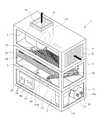
본 발명의 제1실시예에 따른 선박용 공기조화기(1)는 도 1 내지 도 4 에 도시된 바와 같이, 흡기구(11) 및 배기구(13)가 형성된 본체(10)와; 상기 본체에 수 용되어 냉매를 압축하는 압축부(110); 상기 압축유닛(110)에 의해 압축된 고온 고압의 냉매를 응축시키는 응축부(120); 상기 응축유닛(120)에 의해 응축된 냉매를 저압으로 팽창시키는 팽창부(130); 상기 팽창부(130)에 의해 팽창된 냉매를 증발시키는 증발부(140); 및 상기 증발부(140)에 의해 냉각된 공기를 상기 배기구(13)를 향해 송풍하는 송풍부(150)를 포함한다.The
상기 본체(10)는 상기 압축부(110) 및 상기 응축부(120)가 배치되는 기계실(2)과; 상기 팽창부(130) 및 상기 증발부(140)가 배치되는 증발실(3)과; 상기 송풍부(150)를 수용하는 송풍실(4)을 포함한다.The
상기 본체(10)는 무게를 줄이기 위해 알루미늄 재질로 만들어지는 것이 바람직하다.The
경우에 따라서, 상기 팽창부(130)는 상기 기계실(2)에 배치될 수도 있다.In some cases, the
여기서, 상기 선박용 공기조화기(1)는 상기 기계실(2), 상기 증발실(3) 및 상기 송풍실(4)의 전면(前面) 각각 독립적으로 개폐할 수 있는 복수의 전면커버(21, 22, 23)를 포함한다. 경우에 따라서는, 상기 기계실(2) 및 상기 증발실(3)의 전면을 개방하는 제1전면커버(미도시)와 상기 송풍실(4)의 전면을 개방하는 제2전면커버(미도시)의 2개의 커버를 포함할 수도 있다.Here, the ship air conditioner (1) is a plurality of front cover (21, 22) that can be opened and closed independently of the front of the machine room (2), the evaporation chamber (3) and the blowing chamber (4), respectively. , 23). In some cases, a first front cover (not shown) for opening the front surfaces of the
또한, 상기 선박용 공기조화기(1)는 상기 본체(10)의 측면을 개폐 가능한 복수의 사이드 커버(24, 25, 26)를 더 포함할 수 있다.In addition, the
여기서, 상기 복수의 사이드 커버(24, 25, 26)는 도 1에 도시된 바와 같이, 각각 상기 기계실(2), 상기 증발실(3) 및 상기 송풍실(4)의 측면을 각각 기폐 가능 하도록 마련될 수 있다. 경우에 따라서, 상기 기계실(2) 및 상기 증발실(3)을 개폐 가능한 복수의 사이드 커버(24, 25)는 하나로 마련될 수도 있다.Here, the plurality of side covers 24, 25, 26 are respectively capable of closing the side surfaces of the
상기 복수의 사이드 커버(24, 25, 26) 중 상측에 배치된 상부 사이드 커버(26)는 상기 흡기구(11)를 통해 공기유입이 가능하도록 루버(26a)가 형성될 수 있다.The
여기서, 상기 복수의 전면커버(21, 22, 23) 및 상기 복수의 사이드커버(24, 25, 26)는 중량절감을 위해 모두 알루미늄 재질로 형성되는 것이 바람직하다.Here, the plurality of front covers 21, 22, 23 and the plurality of side covers 24, 25, and 26 may be all made of aluminum to reduce weight.
상기 압축부(100)는 디스플레이스먼트형 압축방식이 사용될 수 있다. 즉, 압축부(100) 내에 실린더(미도시)와, 상기 실린더(미도시) 내에 왕복운동하는 피스톤(미도시)을 포함하여, 상기 피스톤(미도시)의 왕복운동과 미도시된 밸브의 개폐에 따라 상기 증발부(140)로부터 유입된 냉매를 압축하여 응축부(120)로 배출한다.The compression unit 100 may be a displacement type compression method. That is, including a cylinder (not shown) in the compression unit 100, and a piston (not shown) reciprocating in the cylinder (not shown), the reciprocating motion of the piston (not shown) and opening and closing of the valve not shown As a result, the refrigerant introduced from the
상기 응축부(120)는 상기 압축부(100)에 의해 압축된 고온 고압의 냉매와 상기 본체(10)의 외부에 노출된 해수(海水) 유입관(27)을 통해 유입된 해수를 서로 열 교환시킨다.The
상기 응축부(120)는 원통형의 케이스(121)와; 상기 케이스(121) 내부에 상기 케이스(121)의 길이방향을 따라 배치된 복수의 해수 파이프(123)를 포함한다. 상기 해수 파이프(123)는 그 외면의 표면적을 넓히기 위해 원주방향을 따라서 형성된 요철부(124)를 더 포함할 수 있다.The
보다 상세하게 설명하면, 상기 해수유입관(27)을 통해 유입된 해수는, 도 3a에 도시된 바와 같이, 상기 응축부(120)의 케이스(121) 내부에 배치된 다수의 해수 파이프(123)를 통과하면서 상기 해수파이프(123)의 외부의 상기 고온고압의 냉매와 열교환한다. 상기 케이스(121) 내의 냉매(E)는 냉매유입구(도 2의 129a)를 통해서 상기 압축부(100)로부터 유입된다.In more detail, the seawater introduced through the
상기 열교환된 냉매는 냉매유출구(도 2의 129b)를 통해서 상기 팽창부(130)로 전달된다.The heat exchanged refrigerant is delivered to the
경우에 따라서, 상기 냉매유출구는 상기 케이스(121)의 길이방향을 따라 복수개 마련될 수 있고, 이때, 복수개의 냉매유출구를 통해 유출되는 냉매가 합류되는 합류관(미도시)과 상기 팽창부(130)를 연결할 수도 있다.In some cases, the refrigerant outlet may be provided in plural along the length direction of the
상기 팽창부(130)는 팽창밸브를 포함한다. 팽창밸브는 상기 증발부(140) 출구의 냉매증기의 과열도(superheat)를 일정하게 유지시키면서 냉매의 유동량(flow)을 조절가능한 온도감응식 팽창밸브(Thermostatic Expansion Valve), 전자팽창밸브(EEV) 및 증발부(140) 출구의 압력을 일정하기 유지시키면서 냉매의 유동량(flow)을 조절 가능한 자동팽창밸브(Automatic Expansion Valve) 중 적어도 어느 하나를 포함할 수 있다. 경우에 따라서, 상기 팽창밸브는 모세관으로 대체될 수도 있다.The
한편, 상기 증발부(140)는 도 3a, 도 3b 및 도 4에 도시된 바와 같이, 상기 팽창부(130)와 연결되는 복수의 냉매관(142, 143, 144, 145, 146, 147)과; 외관을 형성하며 내부에 상기 복수의 냉매관(142, 143, 144, 145, 146, 147)의 일부를 수용하는 샤시(141)와; 상기 복수의 냉매관(142, 143, 144, 145, 146, 147)이 관통되며 상기 샤시(141)의 폭(W)방향으로 연장된 다수의 증발핀(141d)을 포함한다.Meanwhile, as illustrated in FIGS. 3A, 3B, and 4, the
상기 샤시(141) 및 상기 증발핀(141d)은 중량 절감을 위해 알루미늄 재질로 만들어지는 것이 바람직하다.The
상기 샤시(141)는 상기 본체(10)의 정면 프레임(15)에 체결구(S)로 연결되는 제1플랜지(141a)와 상기 본체(10)의 후면 프레임(미도시)에 연결되는 제2플랜지(141b)를 포함한다.The
상기 복수의 냉매관(142, 143, 144, 145, 146, 147)은 각각 그 일단(一端)은 팽창부(130)에 연결되고 그 타단은 냉매합류관(148)에 연결된다. 상기 복수의 냉매관(142, 143, 144, 145, 146, 147)은 상기 팽창부(130) 및 상기 냉매합류관(148)과 용접으로 결합될 수 있다.Each of the plurality of
상기 샤시(141)는 상기 복수의 냉매관(142, 143, 144, 145, 146, 147)이 통과하는 복수의 관통공(149a, 149b, 149c, 149d, 149e, 149f, 149g, 149h, 149i, 149j, 149k, 149l)이 형성된다. 상기 냉매관(142)은 관통공(149a)을 통과하여 상기 샤시(141) 내부로 수용되며 상기 관통공(149g)을 통과하여 상기 샤시(141) 외부로 노출되어 상기 냉매합류관(148)과 연결된다. 그와 동일한 방식으로, 다른 냉매관인 상기 냉매관(143), 상기 냉매관(144), 상기 냉매관(145), 상기 냉매관(146) 및 상기 냉매관(147)은 각각 관통공(149b, 149h), 관통공(149c, 149i), 관통공(149d, 149j), 관통공(149e, 149k) 및 관통공(149f, 149l)을 통해 상기 샤시(141) 내부로 수용되고 상기 샤시(141)외부로 노출된다.The
여기서, 상기 복수의 냉매관(142, 143, 144, 145, 146, 147)은 서로 연결되지 않고 서로 독립적으로 상기 샤시(141) 내에 배치된다.Here, the plurality of
또한, 상기 복수의 냉매관(142, 143, 144, 145, 146, 147)은 도 3b에 도시된 바와 같이, 상기 샤시(141)의 폭방향(W)을 따라서 균등한 영역(C)으로 배치될 수 있다. 여기서, 상기 복수의 냉매관(142, 143, 144, 145, 146, 147)은 각각 상기 균등영역(C) 내에서 동일한 패턴으로 상기 샤시(141) 내부에서 순환하도록 배치될 수 있다.In addition, the plurality of
즉, 상기 복수의 냉매관(142, 143, 144, 145, 146, 147)은 서로 동일한 패턴으로 상가 샤시(141) 내에 배치될 수 있다. 이에 따라, 상기 복수의 냉매관(142, 143, 144, 145, 146, 147)이 배치된 상기 증발부(140)는 상기 폭방향(W)을 따라서 균등하게 열을 흡수하여 내기를 냉각시킬 수 있다.That is, the plurality of
또한, 상기 증발부(140)의 폭(W)의 길이는 상기 본체(10)의 폭(B)보다 길며, 상기 본체의 바닥면과 평행한 평면(P)에 대해 소정각도(θ)로 경사지게 배치된다.In addition, the length of the width (W) of the
여기서, 상기 소정각도(θ)는 30도(degree)이상 40도이하인 것이 바람직하다. 이는 상기 증발부(140)에 맺힌 응축수가 후술할 상기 본체(10)의 후면에 배치된 응축수받이(180)로 내려가게 하기 위함이다. 상기 소정각도(θ)는 30도 미만이 되면 상기 증발부(140)에 맺힌 응축수가 상기 기계실(2) 내부로 떨어지게 되고, 상기 소정각도(θ)가 40도를 초과하게 되면 상기 증발부(140)가 상기 본체(10) 내에서 차지하는 높이(h)로 인해 공기조화기(1)의 높이(H)가 커지고, 결과적으로 부피가 커지는 문제점이 있다.Here, the predetermined angle θ is preferably 30 degrees or more and 40 degrees or less. This is to allow the condensed water formed in the
또한, 상기 선박용 공기조화기(1)는 응축수받이(180)를 더 포함한다.In addition, the
상기 응축수받이(180)는 대체로 "ㄷ"자 형태의 단면 형상을 가지며, 개방된 부분이 상기 증발부(140)를 향하도록 배치된다. 상기 응축수받이(180)는 미도시된 응축수 배출공을 갖는다. 상기 응축수 배출공에는 배출파이프가 연결되며 상기 배출파이프를 통해 상기 응축수가 기외로 배출된다.The
한편, 상기 송풍부(150)는 상기 증발부(140) 상측에 배치된다. 상기 증발부(140)에 의해 냉각된 내기를 상기 배기구(13)를 향해 송풍한다.On the other hand, the
상기 배기구(13) 주위로 덕트연결부(14)가 형성될 수 있다. 상기 덕트연결부(14)에는 상기 공기조화기(1)가 설치될 장소에 기설치된 덕트(미도시)에 연결된다.A
상기 송풍부(150)는 송풍팬(151)을 포함한다.The
상기 송풍부(150)가 상기 증발부(140)에 의해 냉각된 내기를 상기 배기구(13)를 향해 송풍함에 따라 상기 흡기구(11)를 통해 외기가 유입된다. 그리고, 상기 유입된 외기는 상기 증발부(140)에 의해 다시 냉각된다.As the
한편, 본 발명에 따른 선박용 공기조화기(1)는 도 2, 도 3a 및 도 4에 도시된 바와 같이, 전열히터(170)를 더 포함할 수 있다.Meanwhile, the
상기 전열히터(170)는 상기 증발부(140)의 상기 샤시(141)에 결합될 수 있다.The
상기 전열히터(170)는 미도시된 전원공급부로부터 전원이 공급되면 발열하는 복수의 히트코어(171)와, 상기 복수의 히트코어(171) 각각에 상기 히트코어(171)의 길이방향을 따라 배치된 다수의 방열핀(173)을 포함한다.The
또한, 상기 선박용 공기조화기(1)는 온도센서(미도시); 설정된 온도와 상기 온도센서(미도시)에 의해 측정된 온도를 기초로 상기 압축부(110) 및 상기 전열히터(170)를 제어하는 제어부(160)를 더 포함한다.In addition, the marine air conditioner (1) is a temperature sensor (not shown); The
상기 제어부(160)는 온도를 설정하는 온도설정부(164); 상기 온도센서(미도시)에 의해 측정된 현재온도 또는 상기 온도설정부(164)에 의해 설정된 온도를 표시하는 표시패널(165); 상기 압축부(110), 상기 응축부(120), 상기 팽창부(130) 중 적어도 어느 하나의 인입압력 또는 토출압력을 표시하는 압력계(162); 상기 온도설정부(164), 상기 표시패널(165) 및 상기 압력계(162)를 수용하는 컨트롤 박스(161)를 포함할 수 있다.The
상기 제어부(160)는 현재온도가 설정온도보다 소정치 미만인 경우, 상기 전열히터(170)를 ON시켜 난방 운전한다. 반대로, 현재온도가 설정온도보다 소정치 초과하는 경우, 상기 압축부(110)를 구동하여 냉방 운전한다.When the present temperature is less than a predetermined value than the set temperature, the
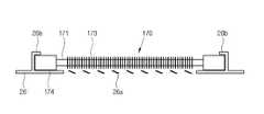
도 5a 및 도 5b는 본 발명의 제2실시예에 따른 공기조화기의 전열히터(170)의 배치를 보여준다. 전열히터(170)의 배치를 제외하고는 상술한 제1실시예와 동일하므로 자세한 설명은 생략하기로 한다.5a and 5b show the arrangement of the
제2실시예의 전열히터(170)는, 제1실시예의 그것이 상기 증발부(140)의 샤시(141)의 상부에 배치된 것과는 다르게, 상부 사이드 커버(26')에 배치된다.The
상기 전열히터(170)는 상기 상부 사이드 커버(26')에 착탈 가능하게 설치될 수 있다. 상기 전열히터(170)는 상기 상부 사이드커버(26')에 상하로 각각 배치된 결합돌기(26b)에 걸림결합 될 수 있다. 상기 전열히터(170)를 누르면 상기 상하로 배치된 결합돌기(26b)사이가 벌어지면서 상기 전열히터(170)가 수용될 수 있도록, 상기 결합돌기(26b)는 탄성재질로 제작되는 것이 바람직하다.The
경우에 따라서, 상기 결합돌기(26b)는 도 5b와 같이 상기 전열히터(170)와 걸림 결합되는 걸림결합위치와, 상기 걸림결합위치로부터 이격되어 상기 걸림결합이 해제되는 해제위치간을 이동가능하게 마련될 수도 있다.In some cases, as shown in FIG. 5B, the
상기 커버(26)와 상기 결합돌기(26b)는 일체로 형성될 수도 있다.The
또한, 상기 상부 사이드커버(26')는 상기 전열히터(170)가 횡방향으로 이탈되는 것을 방지하기 위해 마련된 복수의 스톱퍼(26c)를 더 포함할 수 있다.In addition, the upper side cover 26 ′ may further include a plurality of
경우에 따라서, 상기 상부 사이드 커버(26')와 상기 전열히터(170)사이에 상기 전열히터(170)의 열이 직접 상기 상부 사이드커버(26')로 전달되지 않도록 단열재(미도시)가 포함될 수 있다.In some cases, a heat insulator (not shown) may be included between the upper side cover 26 'and the
또한, 상기 상부 사이드 커버(26')의 루버(26a)와 상기 전열히터(170)의 상기 방열핀(173)간의 간격을 적정하게 유지하기 위해 상기 커버(26')와 상기 전열히터(170)의 바닥면(174) 사이에 스페이서(미도시)가 설치될 수 있다. 상기 스페이서(미도시)는 상기 커버(26')와 일체로 상기 전열히터(170)를 향해 소정높이로 돌출되게 형성될 수도 있다.In addition, the cover 26 'and the
상기 전열히터(170)가 상기 상부 사이드 커버(26')에 착탈 가능하게 부착됨으로써 상기 전열히터(170)를 정비하는 것이 간편하여 정비성이 향상된다.Since the
또한, 난방운전 시 상기 흡기구(11)를 통해 유입된 공기가 바로 전열히터(170)를 통과하면서 가열되므로 난방효과가 향상될 수 있다.In addition, since the air introduced through the
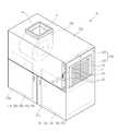
본 발명의 제3실시예에 따른 선박용 공기조화기(1a)는 도 6 내지 도 8에 도 시된 바와 같이, 흡기구(11) 및 배기구(13)가 형성된 본체(10a)와; 상기 본체(10a) 내부에 수용된 복수의 압축부(110); 복수의 응축부(120); 복수의 팽창부(130); 및 복수의 증발부(140) 및 하나의 송풍부(150)를 포함한다.As shown in FIGS. 6 to 8, the
복수의 압축부(110); 복수의 응축부(120); 복수의 팽창부(130); 및 복수의 증발부(140)는 각각 좌우측에 배치되어 각각 하나의 독립적인 냉방시스템을 형성한다.A plurality of
복수의 압축부(110), 응축부(120), 팽창부(130), 증발부(140) 및 송풍부(150)는 제1실시예에서 설명한 것과 동일하므로 자세한 설명은 생략한다.Since the plurality of
상기 선박용 공기조화기(1a)는 온도센서(미도시), 온도설정부(미도시) 및 제어부(미도시)를 더 포함한다.The
상기 제어부(미도시)는 온도설정부(미도시)에 설정된 온도와 상기 온도센서(미도시)에 의채 측정된 온도간의 편차에 따라서 상기 복수의 압축부(110)가 동시에 또는 그중 하나만이 구동되도록 상기 복수의 압축부(110)를 제어한다. 가령, 온도편차가 10도(℃)이상인 경우 상기 복수의 압축부(110)를 구동하고, 10도 미만인 경우 하나의 압축부(110)만을 구동할 수 있다.The control unit (not shown) may operate the plurality of
또한, 제3실시예의 상기 선박용 공기조화기(1a)는 필터(200) 및 상기 필터(200)를 교체하기 위한 필터교체용 커버(30)를 더 포함할 수 있다.In addition, the
상기 필터교체용 커버(30)는 별도의 드라이버 없이도 작업자가 손으로 작업할 수 있는 체결구(33)에 의해 상기 본체(10a)에 착탈 가능하게 결합된다.The
상기 필터(200)는 교체방향(D)을 따라서 서로 분리된 제1필터(210) 및 제2필 터(220)를 포함한다.The
상기 제1필터(210)는 상기 흡기구(11)를 통해 유입되는 외기를 필터링하는 필터부(211)와; 상기 교체방향(D)을 따라 상기 본체(10a)의 정면측에 마련된 파지부(213)와; 상기 교체방향(D)을 따라 상기 제2필터(220)측에 마련된 제1걸림부(215)를 포함한다.The
상기 제2필터(220)는 상기 흡기구(11)를 통해 유입되는 외기를 필터링하는 필터부(221)와; 상기 교체방향(D)을 따라 상기 제1걸림부(215)와 걸림결합 가능하게 마련된 제2걸림부(223)을 포함한다.The
작업자가 상기 필터(200)를 교체하는 방법은 다음과 같다.How the operator replaces the
먼저, 체결구(33)를 풀어서 상기 필터교체용 커버(30)를 상기 본체(10a)로부터 탈착한다. 이에 따라, 상기 제1필터(210)의 파지부(213)가 작업자에게 노출된다.First, the
상기 작업자는 노출된 상기 파지부(213)를 당겨 상기 제1필터(210)를 상기 본체(10a)외부로 취출한다.The worker pulls the exposed
상기 제1필터(210)를 취출하는 경우, 상기 제2필터(220)도 상기 제1필터(210)와 상술한 바와 같이, 서로 상기 제1걸림부(215) 및 상기 제2걸림부(223)에 의해 걸림결합되어 있으므로 상기 제2필터(220)도 상기 교체방향(D)으로 이동한다.When the
도 7에 도시된 바와 같이, 상기 제1필터(210)가 상기 본체(10a)에 의해 지지되지 않는 경우, 상기 제1필터(210)는 자중에 의해 하방(F)으로 이탈된다. 즉, 상기 제1걸림부(215) 및 상기 제2걸림부(223)는 상기 교체방향(D)의 가로방향인 자중 방향(F)으로 서로 분리되도록 마련되는 것이 정비성 측면에서 바람직하다.As shown in FIG. 7, when the
그 다음에, 상기 제2필터(220)의 상기 제2걸림부(223)를 잡아당기면 상기 제2필터(220)로 기외로 취출할 수 있다.Next, when the second catching
이는, 상기 제1필터(210) 및 상기 제2필터(220)의 폭(N)이 긴 경우, 이를 교체하기 위해서는 교체방향(D)으로 그에 상응하는 공간이 있어야 하는 데, 실제 선박, 특히 고속정이나 경비정의 경우 그러한 공간이 충분하지 못한 경우가 대부분이다. 따라서, 상기와 같은 필터 교체방식을 채용하면 필터교체 공간이 상기 폭(N)의 반(N/2) 정도 만 있으면 가능하므로 정비시 요구되는 작업공간을 줄일 수 있다.This means that when the width N of the
한편, 상기한 실시예들은 예시적인 것에 불과한 것으로, 당해 기술분야의 통상을 지식을 가진 자라면 이로부터 다양한 변형 및 균등한 타 실시예가 가능하다.On the other hand, the above embodiments are merely exemplary, and those skilled in the art may have various modifications and other equivalent embodiments therefrom.
따라서, 본 발명의 진정한 기술적 보호범위는 하기의 특허청구범위에 기재된 발명의 기술적 사상에 의해 정해져야만 할 것이다.Accordingly, the true scope of protection of the present invention should be determined by the technical idea of the invention described in the following claims.
도 1은, 본 발명의 제1실시예에 따른 선박용 공기조화기의 사시도,1 is a perspective view of a marine air conditioner according to a first embodiment of the present invention,
도 2는, 도 1의 선박용 공기조화기의 전면커버를 개방한 상태에서의 개략 사시도,FIG. 2 is a schematic perspective view of the ship air conditioner of FIG. 1 in an open state;
도 3a는, 도 1의 선박용 공기조화기의 개략 측면도,3A is a schematic side view of the marine air conditioner of FIG. 1,
도 3b는, 도 3a의 요부 확대도,3B is an enlarged view illustrating main parts of FIG. 3A;
도 4는, 도 3a의 k-k 선에 따른 개략도,4 is a schematic view taken along the line k-k of FIG. 3A,
도 5a는, 본 발명의 제2실시예에 따른 선박용 공기조화기의 전열히터가 부착된 커버의 평면도,5A is a plan view of a cover to which a heat transfer heater of a marine air conditioner according to a second embodiment of the present invention is attached;
도 5b는, 도 5a의 j-j선에 따른 개략단면도,5B is a schematic sectional view taken along the line j-j of FIG. 5A,
도 6은, 본 발명의 제3실시예에 따른 선박용 공기조화기의 개략 사시도,6 is a schematic perspective view of a marine air conditioner according to a third embodiment of the present invention;
도 7은, 도 6의 선박용 공기조화기의 필터의 교체방법을 설명하는 도면,7 is a view for explaining a method of replacing a filter of the marine air conditioner of Figure 6,
도 8은 도 6의 필터의 결합관계를 설명하는 도면이다.FIG. 8 is a diagram illustrating a coupling relationship of the filter of FIG. 6.
* 도면의 주요 부분에 대한 부호의 설명 *Explanation of symbols on the main parts of the drawings
1, 1a: 선박용 공기조화기 110: 압축부1, 1a: marine air conditioner 110: compression unit
120: 응축부 130: 팽창부120: condensation unit 130: expansion unit
140: 증발부 141: 샤시140: evaporation unit 141: chassis
141a, 141b: 플랜지 141c: 증발핀141a, 141b:
142, 143, 144, 145, 146, 147: 냉매관142, 143, 144, 145, 146, 147: refrigerant pipe
148: 냉매합류관 150: 송풍팬148: refrigerant confluence pipe 150: blowing fan
160: 제어부 170: 전열히터160: control unit 170: electric heater
26: 상부사이드 커버 30: 필터교체용 커버26: upper side cover 30: filter replacement cover
200: 필터 210: 제1필터200: filter 210: first filter
220: 제2필터 213: 파지부220: second filter 213: gripping portion
215: 제1걸림부 223: 제2걸림부215: first catching portion 223: second catching portion
Claims (5)
Translated fromKoreanPriority Applications (1)
| Application Number | Priority Date | Filing Date | Title |
|---|---|---|---|
| KR1020090020951AKR101202148B1 (en) | 2009-03-11 | 2009-03-11 | Air conditioner for ship |
Applications Claiming Priority (1)
| Application Number | Priority Date | Filing Date | Title |
|---|---|---|---|
| KR1020090020951AKR101202148B1 (en) | 2009-03-11 | 2009-03-11 | Air conditioner for ship |
Publications (2)
| Publication Number | Publication Date |
|---|---|
| KR20100102507A KR20100102507A (en) | 2010-09-24 |
| KR101202148B1true KR101202148B1 (en) | 2012-11-15 |
Family
ID=43007585
Family Applications (1)
| Application Number | Title | Priority Date | Filing Date |
|---|---|---|---|
| KR1020090020951AExpired - Fee RelatedKR101202148B1 (en) | 2009-03-11 | 2009-03-11 | Air conditioner for ship |
Country Status (1)
| Country | Link |
|---|---|
| KR (1) | KR101202148B1 (en) |
Cited By (1)
| Publication number | Priority date | Publication date | Assignee | Title |
|---|---|---|---|---|
| KR101767556B1 (en)* | 2016-07-08 | 2017-08-11 | 대우조선해양 주식회사 | Air conditioning method of engine room in arctic ship |
Families Citing this family (10)
| Publication number | Priority date | Publication date | Assignee | Title |
|---|---|---|---|---|
| EP3150926B1 (en)* | 2015-09-30 | 2020-09-02 | Koja Oy | A marine fan coil device and system |
| EP3211347B1 (en) | 2016-02-26 | 2020-12-30 | LG Electronics Inc. | Air cleaner |
| US20170246577A1 (en) | 2016-02-26 | 2017-08-31 | Lg Electronics Inc. | Air cleaner |
| US10436469B2 (en) | 2016-02-26 | 2019-10-08 | Lg Electronics Inc. | Air cleaner |
| US9950289B2 (en) | 2016-02-26 | 2018-04-24 | Lg Electronics Inc. | Air cleaner |
| EP3211337B1 (en) | 2016-02-26 | 2020-09-23 | LG Electronics Inc. | Air cleaner |
| WO2017146353A1 (en)* | 2016-02-26 | 2017-08-31 | 엘지전자 주식회사 | Air purifier |
| CN111156622B (en) | 2016-02-26 | 2022-04-26 | Lg电子株式会社 | Air cleaner |
| CN111765554B (en) | 2016-02-26 | 2022-02-25 | Lg电子株式会社 | Air cleaner |
| KR20230099805A (en) | 2021-12-28 | 2023-07-05 | 허준영 | Wake-up alarm setting and sleep induction device using EEG analysis |
Citations (1)
| Publication number | Priority date | Publication date | Assignee | Title |
|---|---|---|---|---|
| KR100775612B1 (en)* | 2006-06-23 | 2007-11-13 | 위니아만도 주식회사 | Air conditioner with humidifier and control method |
- 2009
- 2009-03-11KRKR1020090020951Apatent/KR101202148B1/ennot_activeExpired - Fee Related
Patent Citations (1)
| Publication number | Priority date | Publication date | Assignee | Title |
|---|---|---|---|---|
| KR100775612B1 (en)* | 2006-06-23 | 2007-11-13 | 위니아만도 주식회사 | Air conditioner with humidifier and control method |
Cited By (1)
| Publication number | Priority date | Publication date | Assignee | Title |
|---|---|---|---|---|
| KR101767556B1 (en)* | 2016-07-08 | 2017-08-11 | 대우조선해양 주식회사 | Air conditioning method of engine room in arctic ship |
Also Published As
| Publication number | Publication date |
|---|---|
| KR20100102507A (en) | 2010-09-24 |
Similar Documents
| Publication | Publication Date | Title |
|---|---|---|
| KR101202148B1 (en) | Air conditioner for ship | |
| CN105240996B (en) | The control method of air conditioner | |
| WO2010095470A1 (en) | Heat exchanger, outdoor unit, and freezer device | |
| CN106163842A (en) | Vehicular heat pump system | |
| US20200033012A1 (en) | Refrigeration device | |
| CN102252369B (en) | Floor air conditioner and method for removing accumulated water on electric heater therein | |
| JP2015203563A (en) | Refrigerant circulation path | |
| CN108758864A (en) | Air conditioner outdoor unit and defrosting method thereof | |
| US20190219309A1 (en) | Refrigeration apparatus | |
| JP2014088977A (en) | Air conditioning device | |
| JP5892907B2 (en) | Dry cold air equipment | |
| CN109312933A (en) | Radiant panel module, air-conditioning system and air-conditioning method | |
| KR102401265B1 (en) | Heat pump system for vehicle | |
| CN208312763U (en) | Heat pump unit | |
| JP2010210216A (en) | Air conditioning system | |
| KR20170127341A (en) | Refrigerant cycling device for vehicle | |
| CN112971394B (en) | Double-temperature-zone constant-temperature and constant-humidity wine cabinet control method and double-temperature-zone constant-temperature and constant-humidity wine cabinet | |
| KR101097974B1 (en) | Refrigeration warehouse for energy saving | |
| KR20180132211A (en) | Air conditioner and control method thereof | |
| WO2017086183A1 (en) | Internal temperature adjusting device | |
| KR20160068285A (en) | Air conditioning module and system for battery | |
| KR20190139004A (en) | Plume abatement cooling tower and method for controlling thereof | |
| JP7319714B2 (en) | Plate cylinder cooling device | |
| JP3183379U (en) | Refrigerant condenser | |
| KR102262816B1 (en) | Air-conditioning apparatus using phase change material |
Legal Events
| Date | Code | Title | Description |
|---|---|---|---|
| A201 | Request for examination | ||
| PA0109 | Patent application | St.27 status event code:A-0-1-A10-A12-nap-PA0109 | |
| PA0201 | Request for examination | St.27 status event code:A-1-2-D10-D11-exm-PA0201 | |
| PG1501 | Laying open of application | St.27 status event code:A-1-1-Q10-Q12-nap-PG1501 | |
| D13-X000 | Search requested | St.27 status event code:A-1-2-D10-D13-srh-X000 | |
| D14-X000 | Search report completed | St.27 status event code:A-1-2-D10-D14-srh-X000 | |
| E902 | Notification of reason for refusal | ||
| PE0902 | Notice of grounds for rejection | St.27 status event code:A-1-2-D10-D21-exm-PE0902 | |
| R17-X000 | Change to representative recorded | St.27 status event code:A-3-3-R10-R17-oth-X000 | |
| P11-X000 | Amendment of application requested | St.27 status event code:A-2-2-P10-P11-nap-X000 | |
| P13-X000 | Application amended | St.27 status event code:A-2-2-P10-P13-nap-X000 | |
| E902 | Notification of reason for refusal | ||
| PE0902 | Notice of grounds for rejection | St.27 status event code:A-1-2-D10-D21-exm-PE0902 | |
| E13-X000 | Pre-grant limitation requested | St.27 status event code:A-2-3-E10-E13-lim-X000 | |
| P11-X000 | Amendment of application requested | St.27 status event code:A-2-2-P10-P11-nap-X000 | |
| P13-X000 | Application amended | St.27 status event code:A-2-2-P10-P13-nap-X000 | |
| P11-X000 | Amendment of application requested | St.27 status event code:A-2-2-P10-P11-nap-X000 | |
| P13-X000 | Application amended | St.27 status event code:A-2-2-P10-P13-nap-X000 | |
| R17-X000 | Change to representative recorded | St.27 status event code:A-3-3-R10-R17-oth-X000 | |
| P11-X000 | Amendment of application requested | St.27 status event code:A-2-2-P10-P11-nap-X000 | |
| P13-X000 | Application amended | St.27 status event code:A-2-2-P10-P13-nap-X000 | |
| E701 | Decision to grant or registration of patent right | ||
| PE0701 | Decision of registration | St.27 status event code:A-1-2-D10-D22-exm-PE0701 | |
| GRNT | Written decision to grant | ||
| PR0701 | Registration of establishment | St.27 status event code:A-2-4-F10-F11-exm-PR0701 | |
| PR1002 | Payment of registration fee | St.27 status event code:A-2-2-U10-U11-oth-PR1002 Fee payment year number:1 | |
| PG1601 | Publication of registration | St.27 status event code:A-4-4-Q10-Q13-nap-PG1601 | |
| LAPS | Lapse due to unpaid annual fee | ||
| PC1903 | Unpaid annual fee | St.27 status event code:A-4-4-U10-U13-oth-PC1903 Not in force date:20151110 Payment event data comment text:Termination Category : DEFAULT_OF_REGISTRATION_FEE | |
| PC1903 | Unpaid annual fee | St.27 status event code:N-4-6-H10-H13-oth-PC1903 Ip right cessation event data comment text:Termination Category : DEFAULT_OF_REGISTRATION_FEE Not in force date:20151110 | |
| P22-X000 | Classification modified | St.27 status event code:A-4-4-P10-P22-nap-X000 | |
| P22-X000 | Classification modified | St.27 status event code:A-4-4-P10-P22-nap-X000 | |
| R18-X000 | Changes to party contact information recorded | St.27 status event code:A-5-5-R10-R18-oth-X000 | |
| P22-X000 | Classification modified | St.27 status event code:A-4-4-P10-P22-nap-X000 |