KR101202014B1 - Image processor, stereoscopic display device and method for processing image using the same - Google Patents
Image processor, stereoscopic display device and method for processing image using the sameDownload PDFInfo
- Publication number
- KR101202014B1 KR101202014B1KR1020110014628AKR20110014628AKR101202014B1KR 101202014 B1KR101202014 B1KR 101202014B1KR 1020110014628 AKR1020110014628 AKR 1020110014628AKR 20110014628 AKR20110014628 AKR 20110014628AKR 101202014 B1KR101202014 B1KR 101202014B1
- Authority
- KR
- South Korea
- Prior art keywords
- image
- view
- view image
- viewpoint
- object position
- Prior art date
- Legal status (The legal status is an assumption and is not a legal conclusion. Google has not performed a legal analysis and makes no representation as to the accuracy of the status listed.)
- Expired - Fee Related
Links
Images


Classifications
- H—ELECTRICITY
- H04—ELECTRIC COMMUNICATION TECHNIQUE
- H04N—PICTORIAL COMMUNICATION, e.g. TELEVISION
- H04N13/00—Stereoscopic video systems; Multi-view video systems; Details thereof
- H04N13/10—Processing, recording or transmission of stereoscopic or multi-view image signals
- H04N13/106—Processing image signals
- H04N13/156—Mixing image signals
- H—ELECTRICITY
- H04—ELECTRIC COMMUNICATION TECHNIQUE
- H04N—PICTORIAL COMMUNICATION, e.g. TELEVISION
- H04N13/00—Stereoscopic video systems; Multi-view video systems; Details thereof
- H04N13/20—Image signal generators
- H04N13/282—Image signal generators for generating image signals corresponding to three or more geometrical viewpoints, e.g. multi-view systems
- H—ELECTRICITY
- H04—ELECTRIC COMMUNICATION TECHNIQUE
- H04N—PICTORIAL COMMUNICATION, e.g. TELEVISION
- H04N13/00—Stereoscopic video systems; Multi-view video systems; Details thereof
- H04N2013/0074—Stereoscopic image analysis
- H04N2013/0081—Depth or disparity estimation from stereoscopic image signals
Landscapes
- Engineering & Computer Science (AREA)
- Multimedia (AREA)
- Signal Processing (AREA)
- Testing, Inspecting, Measuring Of Stereoscopic Televisions And Televisions (AREA)
Abstract
Translated fromKoreanDescription
Translated fromKorean본 발명의 일 양상은 영상 처리 기술에 관한 것으로, 보다 상세하게는 입체영상을 처리하고 디스플레이하는 기술에 관한 것이다.One aspect of the present invention relates to an image processing technology, and more particularly, to a technology for processing and displaying stereoscopic images.
최근 객체(object)의 입체감을 표현하기 위한 멀티 뷰 디스플레이(multi-view display)가 개발되고 있다. 그러나, 멀티 뷰 디스플레이를 위해 생성된 멀티 뷰 3D 영상은 많지 않다. 대부분의 3D 영상들은 스테레오 타입의 디스플레이에 최적으로 표현될 수 있도록 스테레오(stereo) 영상 형태로 있다. 결국, 멀티 뷰 디스플레이가 점차적으로 일반화될 경우, 멀티 뷰 디스플레이에 스테레오 영상을 표현할 수 있는 영상 처리 기술이 요구된다.Recently, a multi-view display for expressing a three-dimensional appearance of an object has been developed. However, there are not many multi-view 3D images generated for multi-view displays. Most 3D images are in stereo form so that they can be optimally represented on a stereo type display. As a result, when the multi-view display is gradually generalized, an image processing technique capable of representing stereo images on the multi-view display is required.
스테레오 영상은 멀티 뷰 디스플레이에 최적화된 형태가 아니기 때문에, 스테레오 영상에서 멀티 뷰 영상을 생성하는 경우 화질 저하가 발생할 수 있다. 예를 들어, 멀티 뷰 디스플레이는 엘시디(LCD), 렌즈 시트(Lenticular sheet) 또는 시차 장애(parallax barrier)와 같은 영상을 표현할 수 있는 제한 조건이 존재한다. 이러한 제한 조건으로 인해, 시각적 피로를 유발하지 않고 영상을 표현할 수 있는 깊이감(depth) 정도가 감소할 수 있으며 심한 영상 왜곡으로 3D 표현이 불가능할 수 있다. 따라서, 멀티 뷰 디스플레이의 물리적 특성을 고려하여 스테레오 영상으로부터 멀티 뷰 영상을 생성하는 기술이 요구된다.Since the stereo image is not optimized for the multi view display, deterioration of image quality may occur when the multi view image is generated from the stereo image. For example, multi-view displays have constraints that can represent images such as LCDs, lens sheets, or parallax barriers. Due to these limitations, the degree of depth that can represent an image without causing visual fatigue may be reduced, and 3D representation may be impossible due to severe image distortion. Accordingly, there is a need for a technique of generating a multi-view image from a stereo image in consideration of physical characteristics of the multi-view display.
일 양상에 따라, 스테레오 영상으로부터 멀티 뷰 영상을 생성하여, 무안경(non-glass) 방식으로 개발될 입체 TV 및 멀티 뷰 영상을 필요로 하는 모든 입체영상 디스플레이 장치에 적용하는 기술을 제안한다.According to an aspect, a technique of generating a multi-view image from a stereo image and applying it to a stereoscopic TV and a multi-view image display device requiring a multi-view image to be developed in a non-glass method is proposed.
일 양상에 따른 영상 처리장치는 스테레오 영상의 좌시점 영상과 우시점 영상을 대상으로 시점 간의 차이인 시차(disparity)를 추정하는 시차 추정부와, 추정된 시차를 이용하여 영상을 바라보는 시점에 따라 멀티 뷰 영상에서의 적어도 하나의 시점 위치를 결정하는 인터 뷰 발생부와, 적어도 하나의 시점 위치에 기초하여 스테레오 영상으로부터 멀티 뷰 영상을 생성하는 멀티 뷰 생성부를 포함한다.According to an aspect of an exemplary embodiment, an image processing apparatus includes a disparity estimator configured to estimate a disparity, which is a difference between views, of a left view image and a right view image of a stereo image, and a view of an image using the estimated disparity An inter view generator determines at least one viewpoint position in the multi view image, and a multi view generator configured to generate a multi view image from the stereo image based on the at least one viewpoint position.
다른 양상에 따른 영상 처리방법은, 영상 처리장치가 스테레오 영상의 좌시점 영상과 우시점 영상을 대상으로 시점 간의 차이인 시차를 추정하는 단계와, 추정된 시차를 이용하여 영상을 바라보는 시점에 따라 멀티 뷰 영상에서의 적어도 하나의 시점 위치를 결정하는 단계와, 적어도 하나의 시점 위치에 기초하여 스테레오 영상으로부터 멀티 뷰 영상을 생성하는 단계를 포함한다.According to another aspect of the present invention, an image processing apparatus includes estimating a parallax, which is a difference between viewpoints, of a left view image and a right view image of a stereo image, and according to a view point of an image using the estimated parallax. Determining at least one viewpoint position in the multi-view image, and generating a multi-view image from the stereo image based on the at least one viewpoint position.
또 다른 양상에 따른 디스플레이 장치는, 제어신호를 생성하여 입력부와 영상 처리부 및 표시부를 제어하는 제어부와, 제어신호에 기초하여 스테레오 영상을 입력받는 입력부와, 입력받은 스테레오 영상의 좌시점 영상과 우시점 영상을 대상으로 시점 간의 차이인 시차를 추정하고 추정된 시차를 이용하여 영상을 바라보는 시점에 따라 멀티 뷰 영상에서의 적어도 하나의 시점 위치를 결정하며 적어도 하나의 시점 위치에 기초하여 스테레오 영상으로부터 멀티 뷰 영상을 생성하는 영상 처리부와, 제어신호에 기초하여 생성된 멀티 뷰 영상을 표시하는 표시부를 포함한다.According to another aspect of the present invention, a display apparatus includes a controller configured to generate a control signal to control an input unit, an image processor, and a display unit, an input unit that receives a stereo image based on the control signal, a left view image and a right view point of the received stereo image Estimating the parallax, which is the difference between viewpoints, for the image, and determining at least one viewpoint position in the multi-view image according to the viewpoint viewing the image using the estimated disparity, and multiplying from the stereo image based on the at least one viewpoint position. An image processing unit for generating a view image, and a display unit for displaying the multi-view image generated based on the control signal.
일 실시예에 따르면, 스테레오 영상을 구성하는 좌?우시점 영상으로부터 별도의 컨텐츠 제작 없이 멀티 뷰 영상을 생성할 수 있고, 여러 대의 카메라를 통해 멀티 뷰 영상을 생성하는 방식에 비하여 비용이 절감되며 기술을 용이하게 구현하고 전송 문제를 해결할 수 있다.According to an embodiment of the present disclosure, a multi-view image may be generated from a left-right view image constituting a stereo image without additional content production, and a cost may be reduced compared to a method of generating a multi-view image through multiple cameras. Can be easily implemented and transmission problems can be solved.
나아가 스테레오 영상을 통한 멀티 뷰 지원 방식으로 오류 없는 깊이(depth) 인식이 가능함으로써 보다 현실감 있는 입체영상을 제공할 수 있다.Furthermore, multi-view support through stereo images enables error-free depth recognition to provide more realistic stereoscopic images.
나아가 스테레오 영상을 구성하는 좌?우시점 영상을 모두 고려하여 멀티 뷰 영상을 생성함으로써, 출력 멀티 뷰 영상의 화질을 향상시킬 수 있다.Furthermore, the multi-view image may be generated by considering both left and right view images constituting the stereo image, thereby improving the image quality of the output multi-view image.
나아가, 스테레오 영상의 시차(disparity)를 고려하여 스테레오 영상의 시점 위치를 결정함으로써, 자연스러운 멀티 뷰 영상을 제공할 수 있다.Furthermore, by determining the viewpoint position of the stereo image in consideration of the disparity of the stereo image, a natural multi-view image may be provided.
도 1은 본 발명의 일 실시예에 따라 입체영상 디스플레이 장치가 스테레오 영상으로부터 멀티 뷰 영상을 생성하는 프로세스를 설명하기 위한 참조도,
도 2는 본 발명의 일 실시예에 따른 입체영상 디스플레이 장치의 구성도,
도 3은 도 2의 영상 처리부의 세부 구성도,
도 4는 본 발명의 일 실시예에 따라 입체영상이 적용되는 좌우 시점 영상을 도시하는 예시도,
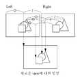
도 5는 본 발명에 따라 생성되는 멀티 뷰 영상을 설명하기 위한 예시도,
도 6은 본 발명의 일 실시예에 따른 인터 뷰 발생부의 내분(internal division)을 통한 시점 위치 결정 프로세스를 설명하기 위한 예시도,
도 7은 본 발명의 일 실시예에 따른 인터 뷰 발생부의 외분(external division)을 통한 시점 위치 결정 프로세스를 설명하기 위한 예시도,
도 8은 본 발명의 일 실시예에 따른 멀티 뷰 생성부의 프로세스를 도시한 예시도,
도 9는 본 발명의 일 실시예에 따른 영상 처리부의 영상 처리방법을 도시한 흐름도이다.1 is a reference diagram for explaining a process of generating a multi-view image from a stereo image by a stereoscopic image display apparatus according to an embodiment of the present invention;
2 is a block diagram of a stereoscopic image display apparatus according to an embodiment of the present invention;
3 is a detailed configuration diagram of an image processor of FIG. 2;
4 is an exemplary diagram illustrating a left and right viewpoint image to which a stereoscopic image is applied according to an embodiment of the present invention;
5 is an exemplary diagram for explaining a multi-view image generated according to the present invention;
6 is an exemplary view for explaining a viewpoint positioning process through internal division of an interview generation unit according to an embodiment of the present invention;
FIG. 7 is an exemplary diagram for describing a viewpoint positioning process through external division of an interview generation unit according to an embodiment of the present invention; FIG.
8 is an exemplary view showing a process of a multi-view generator according to an embodiment of the present invention;
9 is a flowchart illustrating an image processing method of an image processing unit according to an embodiment of the present invention.
이하에서는 첨부한 도면을 참조하여 본 발명의 실시예들을 상세히 설명한다. 본 발명을 설명함에 있어 관련된 공지 기능 또는 구성에 대한 구체적인 설명이 본 발명의 요지를 불필요하게 흐릴 수 있다고 판단되는 경우에는 그 상세한 설명을 생략할 것이다. 또한, 후술되는 용어들은 본 발명에서의 기능을 고려하여 정의된 용어들로서 이는 사용자, 운용자의 의도 또는 관례 등에 따라 달라질 수 있다. 그러므로 그 정의는 본 명세서 전반에 걸친 내용을 토대로 내려져야 할 것이다.Hereinafter, with reference to the accompanying drawings will be described embodiments of the present invention; In the following description of the present invention, a detailed description of known functions and configurations incorporated herein will be omitted when it may make the subject matter of the present invention rather unclear. In addition, the terms described below are defined in consideration of the functions of the present invention, and this may vary depending on the intention of the user, the operator, or the like. Therefore, the definition should be based on the contents throughout this specification.
도 1은 본 발명의 일 실시예에 따라 입체영상 디스플레이 장치(1)가 스테레오 영상으로부터 멀티 뷰 영상을 생성하는 프로세스를 설명하기 위한 참조도이다.1 is a reference diagram for explaining a process of generating a multi-view image by a stereoscopic
사람의 좌, 우안은 하나의 입체 대상물을 관찰할 때 서로 미세하게 다른 위치에서 보게 되므로, 관찰자는 좌, 우안을 통해 서로 상이한 영상 정보를 인식하게 된다. 관찰자는 서로 상이한 영상 정보를 조합하여 입체 대상물에 대한 깊이(depth) 정보를 획득하고, 입체감을 느끼게 된다.Since the left and right eyes of a person are viewed at different positions from each other when one stereoscopic object is observed, the observer recognizes different image information through the left and right eyes. The observer combines different image information to obtain depth information on the three-dimensional object and feels the three-dimensional effect.
도 1을 참조하면, 입체영상 디스플레이 장치(1)는 관찰자가 실제로 입체 대상물을 관찰할 때 관찰자의 좌, 우안이 보게 되는 영상을 관찰자에게 제공함으로써 관찰자로 하여금 입체영상을 느끼게 한다. 이때, 관찰자의 좌, 우안이 보게 되는 영상의 차이를 시차(disparity)라 한다. 여기서, 입체영상은 표시되는 영상이 표시 장치의 일면을 기준면으로 하였을 경우, 표시되는 영상이 기준면으로부터 관찰자 방향으로 다가서서 위치하는 것으로 느껴지거나 기준면에서 관찰자 반대 방향으로 멀어져서 위치하는 것으로 느껴지는 영상을 의미한다. 입체영상 디스플레이 장치(1)는 위에서 정의되는 입체영상을 표시할 수 있는 표시 장치를 의미한다.Referring to FIG. 1, the stereoscopic
도 1에 도시된 바와 같이 본 발명의 입체영상 디스플레이 장치(1)는 스테레오(stereo) 영상으로부터 멀티 뷰(multi-view) 영상을 생성한다. 스테레오 영상은 관찰자가 물체를 좌안으로 바라보는 좌시점 영상과 우안으로 바라보는 우시점 영상을 포함한다. 스테레오 영상에 대해서는 도 4에서 상세히 후술한다. 멀티 뷰 영상은 물체를 여러 사람이 다양한 각도에서 함께 바라보는 즉, 다 시점에서의 영상을 의미한다. 멀티 뷰 영상에 대해서는 도 5에서 상세히 후술한다.As shown in FIG. 1, the stereoscopic
스테레오 카메라(stereo camera)를 통해 실제로 많은 스테레오 컨텐츠(Stereo contents)가 생성되고 있다. 입체영상 컨텐츠로서 스테레오 컨텐츠에 대한 생성이 증가하고 스테레오 카메라를 통해 스테레오 컨텐츠가 생성되는 상황에서 TV 등에 무안경(non-glass) 기반 3D 입체영상을 제공하기 위해서는 멀티 뷰 컨텐츠 생성이 필요하다.Many stereo contents are generated through a stereo camera. In the situation where stereo content is increased as stereoscopic image content and stereo contents are generated through a stereo camera, multi-view content generation is required to provide non-glass based 3D stereoscopic image to a TV.
멀티 뷰 컨텐츠를 생성하기 위해서 다수의 카메라를 사용하면 비용 부담 및 기술 구현에 어려움이 발생한다. 설사 다수의 카메라로 촬영한 영상이 있더라도 많은 데이터로 인한 데이터 전송 문제 때문에 한 장의 영상과 깊이 정보를 함께 전송하여 멀티 뷰 영상을 생성하는 방식은, 깊이 정보 생성 자체에 포함되는 오류 문제로 현실감 있는 멀티 뷰 영상을 생성하기 어렵고, 멀티 뷰를 위한 별도의 컨텐츠를 생성해야 하는 어려움이 있다. 그러나, 본 발명은 하나의 스테레오 영상으로부터 별도의 컨텐츠 제작 없이 멀티 뷰 영상을 생성한다. 이에 따라 비용 및 기술적인 측면의 난관을 해결하고자 한다.Using multiple cameras to generate multi-view content is costly and difficult to implement. Even if there are images taken by multiple cameras, due to the problem of data transmission due to a lot of data, the method of generating a multi-view image by transmitting a single image and depth information together is an error problem included in the depth information generation itself. It is difficult to generate a view image, and it is difficult to generate separate content for multi-view. However, the present invention generates a multi-view image without producing a separate content from one stereo image. Accordingly, we will try to solve the cost and technical difficulties.
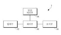
도 2는 본 발명의 일 실시예에 따른 입체영상 디스플레이 장치(1)의 구성도이다.2 is a block diagram of the stereoscopic
도 2를 참조하면, 입체영상 디스플레이 장치(1)는 제어부(10), 입력부(12), 영상 처리부(14) 및 표시부(16)를 포함한다.Referring to FIG. 2, the stereoscopic
제어부(10)는 제어신호를 생성하여 입력부(12)와 영상 처리부(14) 및 표시부(16)를 제어한다.The
입력부(12)는 제어부(10)의 제어신호에 기초하여 스테레오 영상을 입력받는다. 현재 입체영상을 위한 스테레오 컨텐츠에 대해서는 많은 사양 결정이 이루어진 상태로, 스테레오 컨텐츠 포맷에 대해서 사이드바이사이드(side-by-side) 방식 혹은 탑-바텀(top-bottom) 방식과 같이 일반적인 멀티미디어 코덱 구조에서도 지원 가능한 포맷들이 결정된 상태이다. 일 양상에 따르면 입력부(12)는 사이드바이사이드 방식으로 구성된 좌측 및 우측 영상 또는 탑-바텀 방식으로 구성된 좌측 및 우측 영상을 입력받는다.The
영상 처리부(14)는 입력부(12)로부터 입력받은 스테레오 영상의 좌시점 영상과 우시점 영상을 대상으로 시점 간의 차이인 시차(disparity)를 추정한다. 그리고, 추정된 시차를 이용하여 영상을 바라보는 시점에 따라 멀티 뷰 영상에서의 적어도 하나의 시점(view) 위치를 결정한다. 그리고, 적어도 하나의 시점 위치에 기초하여 스테레오 영상으로부터 멀티 뷰 영상을 생성한다. 영상 처리부(14)의 세부 구성에 대해서는 도 3에서 후술한다.The
표시부(16)는 제어부(10)의 제어신호에 기초하여 영상 처리부(14)에서 생성된 멀티 뷰 영상을 표시한다. 이때, 표시부(16)는 액정 표시 방식, 유기 발광 표시 방식, 플라즈마 표시 방식 또는 전계 방출 표시 방식 등을 이용할 수 있으나 이에 한정되지 않는다.The
도 3은 도 2의 영상 처리부(14)의 세부 구성도이다.3 is a detailed block diagram of the
도 3을 참조하면, 영상 처리부(14)는 시차 추정부(140), 인터 뷰 발생부(142) 및 멀티 뷰 생성부(144)를 포함한다.Referring to FIG. 3, the
시차 추정부(Disparity extraction unit)(140)는 스테레오 영상의 좌시점 영상과 우시점 영상을 대상으로 시점 간의 차이인 시차(disparity)를 추정한다. 이를 위해, 시차 추정부(140)는 스테레오 영상의 좌?우시점 영상으로부터 각각 객체(object)를 추출하고 각 객체 간의 시차를 추출한다.The
시차 추정부(140)는 스테레오 영상의 좌?우시점 영상 각각의 픽셀별 시차를 추출할 수 있다. 이때, 시차는 좌?우시점 영상 각각의 픽셀별 시차(disparity) 값을 의미할 수 있다. 예를 들면, 시차 추정부(140)는 좌?우시점 각각의 시차도(disparity map)를 이용하여 시차를 추출할 수 있다. 여기서, 시차도는 동일한 객체에 대해 좌?우시점 영상의 시차에 따라 발생하는 위치 차이 정보를 나타낸다.The
인터 뷰 발생부(Inter-view generation unit)(142)는 추정된 시차를 이용하여 영상을 바라보는 시점(view)에 따라 멀티 뷰 영상에서의 시점 위치를 결정한다. 인터 뷰 발생부(142)는 멀티 뷰 관점에서 새로운 시점에 대한 객체의 새로운 위치를 시차 간의 내분(internal division) 또는 외분(external division)을 통해 결정할 수 있다.The
일 실시예에 따르면 인터 뷰 발생부(142)는 좌시점 영상의 객체 위치와 우시점 영상의 객체 위치를 내분하여 멀티 뷰 영상에서의 새로운 시점 위치를 결정한다. 이때 새로운 시점 위치는 좌시점 영상과 우시점 영상 사이에 위치하게 된다. 이에 대한 상세한 설명은 도 6에서 후술한다.According to an embodiment, the
다른 실시예에 따르면 인터 뷰 발생부(142)는 좌시점 영상의 객체 위치와 우시점 영상의 객체 위치를 외분하여 멀티 뷰 영상에서의 새로운 시점 위치를 결정한다. 이때, 새로운 시점 위치는 좌시점 영상의 객체 위치와 우시점 영상을 벗어나서 위치하게 된다. 이에 대한 상세한 설명은 도 7에서 후술한다.According to another exemplary embodiment, the
멀티 뷰 생성부(Multi-view formatting unit)(144)는 인터 뷰 발생부(142)에 의해 결정된 적어도 하나의 시점 위치에 기초하여 스테레오 영상으로부터 멀티 뷰 영상을 생성한다. 일 실시예에 따르면 멀티 뷰 생성부(144)는 시점에 따라 상이한 시점 위치를 갖는 다수 개의 영상 내 픽셀을 혼합하여 멀티 뷰 영상을 생성한다. 이에 대한 상세한 설명은 도 8에서 후술한다.The
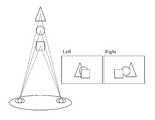
도 4는 본 발명의 일 실시예에 따라 입체영상이 적용되는 좌우 시점 영상을 도시하는 예시도이다.4 is an exemplary diagram illustrating a left and right viewpoint image to which a stereoscopic image is applied according to an embodiment of the present invention.
도 4를 참조하면, 한 사람이 물체를 인식할 때 왼쪽 눈과 오른쪽 눈으로 보게 되는 영상이 서로 상이하며, 이러한 차이로 인해 입체감을 느끼게 된다. 일반적으로 사람의 두 눈은 약 6.5cm(Inter-Ocular Distance or IOD) 정도 떨어져 있다. 그래서 우리가 물체를 볼 때 각각의 눈은 물체의 약간 다른 면을 보게 된다. 이를 좌우 양안에 의한 시차(Disparity)라고 하는데, 이 시차는 뇌에서 합성되어 입체감을 가지는 상으로 지각된다. 이 원리가 3차원 영상 재현에 응용되는 기본 원리이다. 예를 들어 설명하면, 육면체의 물체를 두 눈으로 바라보았을 때, 우리의 뇌는 양쪽 눈에서 인지된 사물의 상에서 비슷한 부분을 감지하게 된다. 그리고 이 각각 다르게 느껴지는 상을 통해 그들 위치에 따라 생기는 차이(parallax difference)를 인지해 사물의 깊이(혹은 눈과 물체 간의 거리), 즉 입체감을 느끼게 된다.Referring to FIG. 4, when a person recognizes an object, the images seen by the left eye and the right eye are different from each other, and the user may feel a three-dimensional effect due to this difference. In general, both eyes are about 6.5 cm (Inter-Ocular Distance or IOD) apart. So when we look at an object, each eye sees a slightly different side of the object. This is called disparity due to left and right binoculars, which are synthesized in the brain and perceived as having a three-dimensional effect. This principle is the basic principle applied to 3D image reproduction. For example, when looking at an object from a cube with two eyes, our brain senses a similar part of the perceived image in both eyes. Each of these differently perceived images recognizes the parallax difference between their positions, and gives a sense of depth (or distance between eyes and objects), or three-dimensionality.
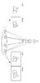
도 5는 본 발명에 따라 생성되는 멀티 뷰 영상을 설명하기 위한 예시도이다.5 is an exemplary diagram for describing a multi-view image generated according to the present invention.
도 5를 참조하면, 멀티 뷰(multi-view) 영상은 물체를 여러 사람이 다양한 각도에서 함께 보는 즉, 다 시점에서의 영상을 의미한다. 예를 들면 도 5에 도시된 바와 같이 실선으로 표시한 사람의 양쪽 눈의 영상과 새로 등장한 점선으로 표시한 사람의 양쪽 눈의 영상은 서로 상이하다. 본 발명은 실선에 해당하는 사람이 느낀 양쪽 눈의 영상을 통해 점선에 해당하는 새로운 사람이 느끼는 영상을 생성하는 것이고, 이는 새로운 사람의 위치에 따라 여러 장이 생성될 수 있다.Referring to FIG. 5, a multi-view image refers to an image of multiple objects, that is, multiple views of an object. For example, as illustrated in FIG. 5, images of both eyes of a person represented by a solid line and images of both eyes of a person represented by a newly appeared dotted line are different from each other. The present invention generates an image felt by a new person corresponding to a dotted line through images of both eyes felt by a person corresponding to a solid line, which may be generated according to the position of the new person.
도 6은 본 발명의 일 실시예에 따른 인터 뷰 발생부(142)의 내분(internal division)을 통한 시점 위치 결정 프로세스를 설명하기 위한 예시도이다.FIG. 6 is an exemplary diagram for describing a viewpoint positioning process through internal division of the
도 3 및 도 6을 참조하면, 인터 뷰 발생부(142)는 새로운 위치에 각 객체를 위치시켜 새로운 시점(view)에 대한 영상을 생성하는데, 좌시점 영상의 객체 위치와 우시점 영상의 객체 위치를 내분하여 새로운 시점에 대한 영상을 생성한다. 단, 시차를 감안하여 앞뒤를 고려해서 시점 위치를 결정한다. 전체 프레임의 위치, 각 객체의 위치 계산을 위한 내분 비율은 일정하다. 도 6에서는 O, |로 내분 비율을 표시하였다. 즉 좌시점 영상에서 객체의 위치를 x1, 우시점 영상에서 객체의 위치를 x2라 하고, 각 위치의 내분 비율이 m:n 이라 가정하면 새로운 가로 방향의 시점 위치(x)는 다음 수학식 1과 같이 나타낼 수 있다.3 and 6, the

단, 세로 방향의 시점 위치 y는 기존 좌시점 영상 또는 우시점 영상과 동일하다고 가정한다. 이때 새로운 시점 위치는 좌시점 영상과 우시점 영상 사이에 위치하게 된다. 도 6에서의 내분 비율은 일 실시예일 뿐 이외의 다양한 실시예가 가능하다.However, it is assumed that the view point y in the vertical direction is the same as the existing left view image or the right view image. At this time, the new view position is located between the left view image and the right view image. The anticorrosion ratio in FIG. 6 is only one embodiment and various embodiments are possible.
도 7은 본 발명의 일 실시예에 따른 인터 뷰 발생부(142)의 외분(external division)을 통한 시점 위치 결정 프로세스를 설명하기 위한 예시도이다.FIG. 7 is an exemplary diagram for describing a viewpoint positioning process through external division of the
도 3 및 도 7을 참조하면, 인터 뷰 발생부(142)는 새로운 위치에 각 객체를 위치시켜 새로운 시점에 대한 영상을 생성하는데, 좌시점 영상의 객체 위치와 우시점 영상의 객체 위치를 내분하여 생성한다. 단, 시차를 감안하여 앞뒤를 고려해서 시점 위치를 결정한다. 전체 프레임의 위치, 각 객체의 위치 계산을 위한 외분 비율은 일정하다. 도 7에서는 O, |로 내분 비율을 표시하였다. 즉 좌시점 영상에서 객체의 위치를 x1, 우시점 영상에서 객체의 위치를 x2라고 하고, 각 위치의 외분 비율이 m:n이라면 새로운 가로 방향의 시점 위치(x)는 다음 수학식 2와 같이 나타낼 수 있다.3 and 7, the

단, 세로 방향의 시점 위치 y는 기존 좌시점 영상 또는 우시점 영상과 동일하다고 가정한다. 이때 새로운 시점 위치는 좌시점 영상과 우시점 영상 사이에 위치하게 된다. 도 7에서의 내분 비율은 일 실시예일 뿐 이외의 다양한 실시예가 가능하다.However, it is assumed that the view point y in the vertical direction is the same as the existing left view image or the right view image. At this time, the new view position is located between the left view image and the right view image. The anticorrosion ratio in FIG. 7 is only one embodiment and various embodiments are possible.
도 8은 본 발명의 일 실시예에 따른 멀티 뷰 생성부(144)의 프로세스를 도시한 예시도이다.8 is an exemplary diagram illustrating a process of the
도 3 및 도 8을 참조하면, 멀티 뷰 생성부(144)는 사람들이 입체로 느낄 수 있도록 여러 시점에 대해 생성된 여러 장의 멀티 뷰 영상 내 픽셀을 혼합하여 하나의 멀티 뷰 출력 영상을 생성한다. 예를 들어, 도 8에 도시된 바와 같이 하나의 패널을 통해 출력되는 영상은 제1 시점에 대해 생성된 제1 픽셀과 제2 시점에 대해 생성된 제2 픽셀을 각각 구분하여 교대로 배치한다. 이때 제1 위치의 관찰자에 보이는 출력 영상과 제2 위치의 관찰자에 보이는 출력 영상이 서로 상이하게 되는데, 예를 들어 패널로부터의 빛을 차단하는 차단수단과 빛을 통과하는 통과수단이 패널 앞에 위치하여 화소가 엇갈리게 보이도록 하는 경우(parallax barrier 방식), 제1 위치의 관찰자에 보이는 출력 영상과 제2 위치의 관찰자에 보이는 출력 영상이 서로 상이하게 되어, 멀티 뷰 출력 영상을 생성할 수 있게 된다.Referring to FIGS. 3 and 8, the
도 9는 본 발명의 일 실시예에 따른 영상 처리부(14)의 영상 처리방법을 도시한 흐름도이다.9 is a flowchart illustrating an image processing method of the
도 3 및 도 9를 참조하면, 영상 처리부(14)는 스테레오 영상의 좌?우 시점 영상을 대상으로 각각 객체(object)를 추출(900)하고, 좌?우 시점 간의 차이인 시차를 추정한다(910).3 and 9, the
이어서, 영상 처리부(14)는 추정된 시차를 이용하여 영상을 바라보는 시점에 따라 멀티 뷰 영상에서의 적어도 하나의 시점 위치를 결정한다(920). 일 실시예에 따르면 좌시점 영상의 객체 위치와 우시점 영상의 객체 위치를 내분하여 좌시점 영상과 우시점 영상 사이에 멀티 뷰 영상에서의 시점 위치를 결정한다. 다른 실시예에 따르면 좌시점 영상의 객체 위치와 우시점 영상의 객체 위치를 외분하여 좌시점 영상과 우시점 영상을 벗어난 위치에 멀티 뷰 영상에서의 시점 위치를 결정한다.Subsequently, the
이어서, 영상 처리부(14)는 적어도 하나의 시점 위치에 기초하여 스테레오 영상으로부터 멀티 뷰 영상을 생성한다(930). 일 실시예에 따르면 시점에 따라 상이한 시점 위치를 갖는 다수 개의 영상 내 픽셀을 혼합하여 하나의 멀티 뷰 영상을 생성한다.In
본 발명의 일 실시예에 따른 영상 처리방법은 다양한 컴퓨터로 구현되는 동작을 수행하기 위한 프로그램 명령을 포함하는 컴퓨터 판독 가능 매체를 포함한다. 컴퓨터 판독 가능 매체는 프로그램 명령, 데이터 파일, 데이터 구조 등을 단독으로 또는 조합하여 포함할 수 있다. 매체는 프로그램 명령은 본 발명을 위하여 특별히 설계되고 구성된 것들이거나 컴퓨터 소프트웨어 당업자에게 공지되어 사용 가능한 것일 수도 있다. 컴퓨터 판독 가능 기록 매체의 예에는 하드 디스크, 플로피 디스크 및 자기 테이프와 같은 자기 매체(magnetic media), CD-ROM, DVD와 같은 광기록 매체(optical media), 플롭티컬 디스크(floptical disk)와 같은 자기-광 매체(magneto-optical media), 및 롬(ROM), 램(RAM), 플래시 메모리 등과 같은 프로그램 명령을 저장하고 수행하도록 특별히 구성된 하드웨어 장치가 포함된다. 프로그램 명령의 예에는 컴파일러에 의해 만들어지는 것과 같은 기계어 코드뿐만 아니라 인터프리터 등을 사용해서 컴퓨터에 의해서 실행될 수 있는 고급 언어 코드를 포함한다.An image processing method according to an embodiment of the present invention includes a computer readable medium including program instructions for performing operations implemented by various computers. Computer-readable media may include, alone or in combination with the program instructions, data files, data structures, and the like. The program instructions may be those specially designed and constructed for the purposes of the present invention, or they may be of the kind well-known and available to those having skill in the computer software arts. Examples of computer-readable recording media include magnetic media such as hard disks, floppy disks, and magnetic tape, optical media such as CD-ROMs, DVDs, and magnetic disks, such as floppy disks. Magneto-optical media, and hardware devices specifically configured to store and execute program instructions, such as ROM, RAM, flash memory, and the like. Examples of program instructions include not only machine code generated by a compiler, but also high-level language code that can be executed by a computer using an interpreter or the like.
이제까지 본 발명에 대하여 그 실시예들을 중심으로 살펴보았다. 본 발명이 속하는 기술분야에서 통상의 지식을 가진 자는 본 발명이 본 발명의 본질적인 특성에서 벗어나지 않는 범위에서 변형된 형태로 구현될 수 있음을 이해할 수 있을 것이다. 그러므로 개시된 실시예들은 한정적인 관점이 아니라 설명적인 관점에서 고려되어야 한다. 본 발명의 범위는 전술한 설명이 아니라 특허청구범위에 나타나 있으며, 그와 동등한 범위 내에 있는 모든 차이점은 본 발명에 포함된 것으로 해석되어야 할 것이다.The embodiments of the present invention have been described above. Those skilled in the art will appreciate that the present invention can be implemented in a modified form without departing from the essential features of the present invention. Therefore, the disclosed embodiments should be considered in an illustrative rather than a restrictive sense. The scope of the present invention is defined by the appended claims rather than by the foregoing description, and all differences within the scope of equivalents thereof should be construed as being included in the present invention.
1 : 입체영상 디스플레이 장치 10 : 제어부
12 : 입력부 14 : 영상 처리부
16 : 표시부 140 : 시차 추정부
142 : 인터 뷰 발생부 144 : 멀티 뷰 생성부1: Stereoscopic Display Device 10: Control Unit
12
16: display unit 140: parallax estimation unit
142: inter-view generator 144: multi-view generator
Claims (9)
Translated fromKorean상기 시차 추정부에 의해 추정된 시차를 이용하여 좌시점 영상의 객체 위치와 우시점 영상의 객체 위치를 내분 또는 외분하되 그 내분 또는 외분의 비율을 달리하여 새로운 시점 위치들을 결정하는 인터 뷰 발생부; 및
상기 인터 뷰 발생부에 의해 결정된 새로운 시점 위치들에 기초하여 상기 스테레오 영상으로부터 멀티 뷰 영상을 생성하는 멀티 뷰 생성부;
를 포함하는 것을 특징으로 하는 영상 처리장치.A parallax estimator estimating a disparity, which is a difference between viewpoints, for a left view image and a right view image of the stereo image;
An interview generator configured to internally or externally divide the object position of the left view image and the object position of the right view image using the disparity estimated by the parallax estimator, and determine new view positions by varying the ratio of the internal or external components; And
A multi-view generator configured to generate a multi-view image from the stereo image based on the new view positions determined by the inter-view generator;
Image processing apparatus comprising a.
상기 좌시점 영상의 객체 위치와 상기 우시점 영상의 객체 위치를 내분하여 상기 좌시점 영상과 상기 우시점 영상 사이에 상기 멀티 뷰 영상에서의 시점 위치를 결정하는 것을 특징으로 하는 영상 처리장치.The method of claim 1, wherein the inter view generator
And determining a viewpoint position in the multi-view image between the left viewpoint image and the right viewpoint image by integrating the object position of the left view image and the object position of the right view image.
상기 좌시점 영상의 객체 위치와 상기 우시점 영상의 객체 위치를 외분하여 상기 좌시점 영상과 상기 우시점 영상을 벗어난 위치에 상기 멀티 뷰 영상에서의 시점 위치를 결정하는 것을 특징으로 하는 영상 처리장치.The method of claim 1, wherein the inter view generator
And dividing the object position of the left view image and the object position of the right view image to determine a view position in the multi-view image at a position outside the left view image and the right view image.
시점에 따라 상이한 시점 위치를 갖는 다수 개의 멀티 뷰 영상 내 픽셀을 혼합하여 하나의 멀티 뷰 영상을 생성하는 것을 특징으로 하는 영상 처리장치.The method of claim 1, wherein the multi-view generator
An image processing apparatus according to claim 1, wherein a multi-view image is generated by mixing pixels in a plurality of multi-view images having different view positions.
스테레오 영상의 좌시점 영상과 우시점 영상을 대상으로 시점 간의 차이인 시차를 추정하는 단계;
상기 추정된 시차를 이용하여 좌시점 영상의 객체 위치와 우시점 영상의 객체 위치를 내분 또는 외분하되 그 내분 또는 외분의 비율을 달리하여 새로운 시점 위치들을 결정하는 단계; 및
상기 결정된 새로운 시점 위치들에 기초하여 상기 스테레오 영상으로부터 멀티 뷰 영상을 생성하는 단계;
를 포함하는 것을 특징으로 하는 영상 처리방법.In the image processing method of the image processing apparatus,
Estimating a parallax that is a difference between viewpoints of the left view image and the right view image of the stereo image;
Determining new view positions by internally or externally dividing the object position of the left view image and the object position of the right view image using the estimated parallax; And
Generating a multi-view image from the stereo image based on the determined new viewpoint positions;
Image processing method comprising a.
상기 좌시점 영상의 객체 위치와 상기 우시점 영상의 객체 위치를 내분하여 상기 좌시점 영상과 상기 우시점 영상 사이에 상기 멀티 뷰 영상에서의 시점 위치를 결정하는 것을 특징으로 하는 영상 처리방법.The method of claim 5, wherein the determining of the viewpoint positions comprises:
And determining a viewpoint position in the multi-view image between the left viewpoint image and the right viewpoint image by integrating the object position of the left view image and the object position of the right view image.
상기 좌시점 영상의 객체 위치와 상기 우시점 영상의 객체 위치를 외분하여 상기 좌시점 영상과 상기 우시점 영상을 벗어난 위치에 상기 멀티 뷰 영상에서의 시점 위치를 결정하는 것을 특징으로 하는 영상 처리방법.The method of claim 6, wherein the determining of the viewpoint positions comprises:
And dividing the object position of the left view image and the object position of the right view image to determine a view position in the multi-view image at a position outside the left view image and the right view image.
시점에 따라 상이한 시점 위치를 갖는 다수 개의 멀티 뷰 영상 내 픽셀을 혼합하여 하나의 멀티 뷰 영상을 생성하는 것을 특징으로 하는 영상 처리방법.The method of claim 6, wherein the generating of the multi-view image comprises:
And generating one multi-view image by mixing pixels in a plurality of multi-view images having different viewpoint positions according to the viewpoints.
상기 제어신호에 기초하여 스테레오 영상을 입력받는 입력부;
상기 입력받은 스테레오 영상의 좌시점 영상과 우시점 영상을 대상으로 시점 간의 차이인 시차를 추정하고, 상기 추정된 시차를 이용하여 좌시점 영상의 객체 위치와 우시점 영상의 객체 위치를 내분 또는 외분하되 그 내분 또는 외분의 비율을 달리하여 새로운 시점 위치들을 결정하며, 결정된 새로운 시점 위치들에 기초하여 상기 스테레오 영상으로부터 멀티 뷰 영상을 생성하는 영상 처리부; 및
상기 제어신호에 기초하여 상기 생성된 멀티 뷰 영상을 표시하는 표시부;
를 포함하는 것을 특징으로 하는 입체영상 디스플레이 장치.A controller configured to generate a control signal to control the input unit, the image processor, and the display unit;
An input unit configured to receive a stereo image based on the control signal;
The parallax, which is a difference between viewpoints, is estimated based on the left view image and the right view image of the input stereo image, and the object position of the left view image and the object position of the right view image are internalized or divided using the estimated disparity. An image processor configured to determine new view positions by varying the ratio of internal or external parts and to generate a multi-view image from the stereo image based on the determined new view positions; And
A display unit configured to display the generated multi-view image based on the control signal;
Stereoscopic display device comprising a.
Priority Applications (1)
| Application Number | Priority Date | Filing Date | Title |
|---|---|---|---|
| KR1020110014628AKR101202014B1 (en) | 2011-02-18 | 2011-02-18 | Image processor, stereoscopic display device and method for processing image using the same |
Applications Claiming Priority (1)
| Application Number | Priority Date | Filing Date | Title |
|---|---|---|---|
| KR1020110014628AKR101202014B1 (en) | 2011-02-18 | 2011-02-18 | Image processor, stereoscopic display device and method for processing image using the same |
Publications (2)
| Publication Number | Publication Date |
|---|---|
| KR20120095136A KR20120095136A (en) | 2012-08-28 |
| KR101202014B1true KR101202014B1 (en) | 2012-11-15 |
Family
ID=46885772
Family Applications (1)
| Application Number | Title | Priority Date | Filing Date |
|---|---|---|---|
| KR1020110014628AExpired - Fee RelatedKR101202014B1 (en) | 2011-02-18 | 2011-02-18 | Image processor, stereoscopic display device and method for processing image using the same |
Country Status (1)
| Country | Link |
|---|---|
| KR (1) | KR101202014B1 (en) |
Families Citing this family (4)
| Publication number | Priority date | Publication date | Assignee | Title |
|---|---|---|---|---|
| KR101918030B1 (en) | 2012-12-20 | 2018-11-14 | 삼성전자주식회사 | Method and apparatus for rendering hybrid multi-view |
| KR101509993B1 (en)* | 2013-11-29 | 2015-04-16 | 영산대학교산학협력단 | Method of estimating perceived depth according to difference of color |
| KR101975246B1 (en)* | 2014-10-10 | 2019-05-07 | 삼성전자주식회사 | Multi view image display apparatus and contorl method thereof |
| CN104284177A (en)* | 2014-10-28 | 2015-01-14 | 天津大学 | Disparity Control Method for Converging Stereo Images |
Citations (1)
| Publication number | Priority date | Publication date | Assignee | Title |
|---|---|---|---|---|
| JPH1032840A (en)* | 1996-04-05 | 1998-02-03 | Matsushita Electric Ind Co Ltd | Multi-view image transmission method and multi-view image display method |
- 2011
- 2011-02-18KRKR1020110014628Apatent/KR101202014B1/ennot_activeExpired - Fee Related
Patent Citations (1)
| Publication number | Priority date | Publication date | Assignee | Title |
|---|---|---|---|---|
| JPH1032840A (en)* | 1996-04-05 | 1998-02-03 | Matsushita Electric Ind Co Ltd | Multi-view image transmission method and multi-view image display method |
Also Published As
| Publication number | Publication date |
|---|---|
| KR20120095136A (en) | 2012-08-28 |
Similar Documents
| Publication | Publication Date | Title |
|---|---|---|
| US8817073B2 (en) | System and method of processing 3D stereoscopic image | |
| KR102030830B1 (en) | Curved multiview image display apparatus and control method thereof | |
| US8451324B2 (en) | Apparatus and method for displaying three dimensional image | |
| US9049435B2 (en) | Image providing apparatus and image providing method based on user's location | |
| US10282891B2 (en) | Apparatus and method for processing three dimensional image on multi-layer display | |
| KR20100135007A (en) | Multiview Video Display Device and Method | |
| JP5625979B2 (en) | Display device, display method, and display control device | |
| JP5402483B2 (en) | Pseudo stereoscopic image creation device and pseudo stereoscopic image display system | |
| WO2009020277A1 (en) | Method and apparatus for reproducing stereoscopic image using depth control | |
| KR101202014B1 (en) | Image processor, stereoscopic display device and method for processing image using the same | |
| KR101721103B1 (en) | Stereoscopic 3d display device and method of driving the same | |
| KR102279816B1 (en) | Autostereoscopic 3d display device | |
| KR101086305B1 (en) | 3D image display device and method | |
| KR102180068B1 (en) | Method and device of generating multi-view image with resolution scaling function | |
| KR101192121B1 (en) | Method and apparatus for generating anaglyph image using binocular disparity and depth information | |
| KR101367121B1 (en) | Volumetric Type 3-Dimension Image Display Device | |
| KR20140113066A (en) | Multi-view points image generating method and appararus based on occulsion area information | |
| KR102142480B1 (en) | Three Dimensional Image Display Device | |
| KR20080113894A (en) | 3D image display device with pivot function | |
| KR101736924B1 (en) | Stereoscopic 3d display device and method of driving the same | |
| KR102293837B1 (en) | 3D display device and driving method thereof | |
| KR101660021B1 (en) | 2D-3D coexistence type display device | |
| Jeong et al. | 11.3: Depth‐Image‐Based Rendering (DIBR) Using Disocclusion Area Restoration | |
| Hwang et al. | Novel multiview generation framework for 3D displays | |
| KR20130051315A (en) | Stereoscopic image subtitle processing method and subtitle processing unit using the same |
Legal Events
| Date | Code | Title | Description |
|---|---|---|---|
| A201 | Request for examination | ||
| PA0109 | Patent application | St.27 status event code:A-0-1-A10-A12-nap-PA0109 | |
| PA0201 | Request for examination | St.27 status event code:A-1-2-D10-D11-exm-PA0201 | |
| E902 | Notification of reason for refusal | ||
| PE0902 | Notice of grounds for rejection | St.27 status event code:A-1-2-D10-D21-exm-PE0902 | |
| P11-X000 | Amendment of application requested | St.27 status event code:A-2-2-P10-P11-nap-X000 | |
| P13-X000 | Application amended | St.27 status event code:A-2-2-P10-P13-nap-X000 | |
| PG1501 | Laying open of application | St.27 status event code:A-1-1-Q10-Q12-nap-PG1501 | |
| E701 | Decision to grant or registration of patent right | ||
| PE0701 | Decision of registration | St.27 status event code:A-1-2-D10-D22-exm-PE0701 | |
| GRNT | Written decision to grant | ||
| PR0701 | Registration of establishment | St.27 status event code:A-2-4-F10-F11-exm-PR0701 | |
| PR1002 | Payment of registration fee | St.27 status event code:A-2-2-U10-U11-oth-PR1002 Fee payment year number:1 | |
| PG1601 | Publication of registration | St.27 status event code:A-4-4-Q10-Q13-nap-PG1601 | |
| R18-X000 | Changes to party contact information recorded | St.27 status event code:A-5-5-R10-R18-oth-X000 | |
| LAPS | Lapse due to unpaid annual fee | ||
| PC1903 | Unpaid annual fee | St.27 status event code:A-4-4-U10-U13-oth-PC1903 Not in force date:20151110 Payment event data comment text:Termination Category : DEFAULT_OF_REGISTRATION_FEE | |
| PC1903 | Unpaid annual fee | St.27 status event code:N-4-6-H10-H13-oth-PC1903 Ip right cessation event data comment text:Termination Category : DEFAULT_OF_REGISTRATION_FEE Not in force date:20151110 | |
| R18-X000 | Changes to party contact information recorded | St.27 status event code:A-5-5-R10-R18-oth-X000 | |
| P22-X000 | Classification modified | St.27 status event code:A-4-4-P10-P22-nap-X000 | |
| PN2301 | Change of applicant | St.27 status event code:A-5-5-R10-R13-asn-PN2301 St.27 status event code:A-5-5-R10-R11-asn-PN2301 |