KR101201083B1 - Medical Multiple Clips, Clip Gun applying the same, Clipping Method using the same - Google Patents
Medical Multiple Clips, Clip Gun applying the same, Clipping Method using the sameDownload PDFInfo
- Publication number
- KR101201083B1 KR101201083B1KR1020110057878AKR20110057878AKR101201083B1KR 101201083 B1KR101201083 B1KR 101201083B1KR 1020110057878 AKR1020110057878 AKR 1020110057878AKR 20110057878 AKR20110057878 AKR 20110057878AKR 101201083 B1KR101201083 B1KR 101201083B1
- Authority
- KR
- South Korea
- Prior art keywords
- clip
- arm
- tightening
- medical
- locking jaw
- Prior art date
- Legal status (The legal status is an assumption and is not a legal conclusion. Google has not performed a legal analysis and makes no representation as to the accuracy of the status listed.)
- Expired - Fee Related
Links
Images


Classifications
- A—HUMAN NECESSITIES
- A61—MEDICAL OR VETERINARY SCIENCE; HYGIENE
- A61B—DIAGNOSIS; SURGERY; IDENTIFICATION
- A61B17/00—Surgical instruments, devices or methods
- A61B17/12—Surgical instruments, devices or methods for ligaturing or otherwise compressing tubular parts of the body, e.g. blood vessels or umbilical cord
- A61B17/128—Surgical instruments, devices or methods for ligaturing or otherwise compressing tubular parts of the body, e.g. blood vessels or umbilical cord for applying or removing clamps or clips
- A61B17/1285—Surgical instruments, devices or methods for ligaturing or otherwise compressing tubular parts of the body, e.g. blood vessels or umbilical cord for applying or removing clamps or clips for minimally invasive surgery
- A—HUMAN NECESSITIES
- A61—MEDICAL OR VETERINARY SCIENCE; HYGIENE
- A61B—DIAGNOSIS; SURGERY; IDENTIFICATION
- A61B17/00—Surgical instruments, devices or methods
- A61B17/08—Wound clamps or clips, i.e. not or only partly penetrating the tissue ; Devices for bringing together the edges of a wound
- A61B17/083—Clips, e.g. resilient
- A—HUMAN NECESSITIES
- A61—MEDICAL OR VETERINARY SCIENCE; HYGIENE
- A61B—DIAGNOSIS; SURGERY; IDENTIFICATION
- A61B17/00—Surgical instruments, devices or methods
- A61B17/10—Surgical instruments, devices or methods for applying or removing wound clamps, e.g. containing only one clamp or staple; Wound clamp magazines
- A—HUMAN NECESSITIES
- A61—MEDICAL OR VETERINARY SCIENCE; HYGIENE
- A61B—DIAGNOSIS; SURGERY; IDENTIFICATION
- A61B17/00—Surgical instruments, devices or methods
- A61B17/12—Surgical instruments, devices or methods for ligaturing or otherwise compressing tubular parts of the body, e.g. blood vessels or umbilical cord
- A61B17/122—Clamps or clips, e.g. for the umbilical cord
- A—HUMAN NECESSITIES
- A61—MEDICAL OR VETERINARY SCIENCE; HYGIENE
- A61B—DIAGNOSIS; SURGERY; IDENTIFICATION
- A61B17/00—Surgical instruments, devices or methods
- A61B17/00234—Surgical instruments, devices or methods for minimally invasive surgery
- A61B2017/00292—Surgical instruments, devices or methods for minimally invasive surgery mounted on or guided by flexible, e.g. catheter-like, means
- A—HUMAN NECESSITIES
- A61—MEDICAL OR VETERINARY SCIENCE; HYGIENE
- A61B—DIAGNOSIS; SURGERY; IDENTIFICATION
- A61B17/00—Surgical instruments, devices or methods
- A61B17/12—Surgical instruments, devices or methods for ligaturing or otherwise compressing tubular parts of the body, e.g. blood vessels or umbilical cord
- A61B2017/12004—Surgical instruments, devices or methods for ligaturing or otherwise compressing tubular parts of the body, e.g. blood vessels or umbilical cord for haemostasis, for prevention of bleeding
Landscapes
- Health & Medical Sciences (AREA)
- Life Sciences & Earth Sciences (AREA)
- Surgery (AREA)
- Molecular Biology (AREA)
- Engineering & Computer Science (AREA)
- Biomedical Technology (AREA)
- Heart & Thoracic Surgery (AREA)
- Medical Informatics (AREA)
- Nuclear Medicine, Radiotherapy & Molecular Imaging (AREA)
- Animal Behavior & Ethology (AREA)
- General Health & Medical Sciences (AREA)
- Public Health (AREA)
- Veterinary Medicine (AREA)
- Reproductive Health (AREA)
- Vascular Medicine (AREA)
- Surgical Instruments (AREA)
Abstract
Translated fromKoreanDescription
Translated fromKorean본 발명은 의료용 다연발 클립과 이를 적용하는 클립 건 및 이들을 이용하는 클리핑 방법에 관한 것으로, 더욱 자세하게는 복강경 또는 내시경 시술 시 체내의 특정 부위에 위치 표시를 하거나 지혈 등을 위해 클리핑하는 의료용 클립과 이를 적용하는 클립 건 및 이들을 이용하는 클리핑 방법에 관한 것이다.
The present invention relates to a medical multi-shot clip and a clip gun using the same, and a clipping method using the same, and more particularly, to a medical clip for clipping a location mark or clipping for a hemostasis, etc. during laparoscopic or endoscopy. The clip gun and the clipping method using them.
내시경 시술 중 출혈 부위를 지혈하거나, 대장 또는 위 등에 발생한 종양 등을 제거하는 수술 전 시술 부위를 표시하기 위해 클립 장치가 사용된다.The clip device is used to mark a preoperative procedure site for bleeding the bleeding site or removing a tumor or the like occurring in the colon or stomach during the endoscopy.
종래의 클립 장치는 구강 또는 항문을 통해 인체 내로 삽입되는 내시경 채널과 같은 삽입관을 따라 클립을 장착한 클립 건을 투입하여 체내의 클리핑 대상체 가까이에 클립 건의 최선단을 위치시킨 후 클립과 연결된 조작와이어를 이용해 클립이 대상체를 클리핑하도록 구성된다.In the conventional clip device, a clip gun equipped with a clip is inserted along an insertion tube such as an endoscope channel inserted into the human body through the oral cavity or an anus so as to position the uppermost end of the clip gun near a clipping object in the body and then connect the operation wire with the clip. The clip is configured to clip the object.
이 경우 조작와이어로 클립을 클립 건 밖으로 밀어내어 클립을 확개시킨 후, 클립으로 대상체를 감싸고, 다시 조작와이어를 당겨 조임링으로 클립을 조임으로써 클리핑이 완료된다.In this case, the clip is pushed out of the clip gun with the operation wire to enlarge the clip, and then the clipping is completed by wrapping the object with the clip and pulling the operation wire again to tighten the clip with the fastening ring.
시술 부위를 표시하기 위해 통상 여러 개의 클립이 사용되는데, 종래 클립 건은 단발 장치이므로, 추가로 클리핑을 하기 위해서는 클립 건을 꺼내 새로운 클립을 재장전한 후 다시 인체 내로 삽입하여 클리핑할 위치를 새로 찾아야 하는데, 이로 인해 시술 시간이 길어지고 시술자 및 환자의 불편도 가중되는 문제가 있다.
Several clips are usually used to mark the area of the procedure.As a conventional clip gun is a single device, in order to perform further clipping, it is necessary to remove the clip gun, reload a new clip, and insert it again into the human body to find a new position for clipping. To this end, there is a problem that the procedure is longer and the inconvenience of the operator and the patient.
본 발명은 전술한 문제점을 해결하기 위한 것으로, 본 발명의 목적은 클립을 밀어내는 것만으로 타기팅과 클리핑이 가능하고, 클립을 연사할 수 있는 의료용 클립과 이를 적용하는 클립 건 및 이들을 이용하는 클리핑 방법을 제공하는 데 있다.
The present invention is to solve the above-mentioned problems, an object of the present invention is to target and clip only by pushing the clip, and to clip the medical clip and the clip gun applying the clip and a clipping method using the same To provide.
전술한 과제를 해결하기 위한 본 발명에 따른 클립 건은 자가확개성(自家擴開性)을 갖는 암과 상기 암의 일단에 구비되어 타깃을 협지하는 파지조(把持爪)와 상기 암의 측부를 포위하며 이동 가능하게 설치되며 일방향으로 이동하여 상기 파지조가 대상체를 클리핑할 수 있도록 상기 암을 조여 주는 조임부와 탄성력에 의해 상기 조임부를 이동시키는 탄성 부재를 구비하는 클립과, 상기 클립이 내부에 적재되는 격납관 및 상기 격납관 내에서 진퇴 가능하게 설치되며 상기 탄성 부재를 압축한 상태로 상기 조임부의 일측을 지탱할 수 있으며 자가확개성을 갖는 클립파지부를 구비한 조작부를 포함한다.Clip gun according to the present invention for solving the above problems is provided with an arm having a self-expansion and one end of the arm to hold a target and the side of the arm holding the target A clip that includes a clip that surrounds and is movably installed and moves in one direction to tighten the arm so that the gripper can clip the object, and an elastic member to move the tightening portion by elastic force, and the clip therein. And an operation unit including a storage tube to be loaded and a retractable installation within the storage tube and capable of supporting one side of the tightening unit in a compressed state of the elastic member and having a clip holding unit having self-expansion.
또는 상기 조작부가 상기 클립파지부 및 상기 클립을 상기 격납관의 출구 측으로 밀어냄에 따라, 상기 암이 상기 격납관을 벗어나며 자가확개성에 의해 확개될 수 있다.Alternatively, as the operation unit pushes the clip holding unit and the clip toward the outlet side of the containment tube, the arm can be expanded by self-expansion while leaving the containment tube.
또는 상기 암의 자가 확개 이후, 상기 조작부가 상기 클립을 더 밀어냄에 따라, 상기 클립파지부가 확개되고, 상기 탄성 부재의 압축이 해제되어 상기 탄성력에 의해 상기 조임부가 이동하며 확개된 상기 암을 조일 수 있다.Or after self-expansion of the arm, as the operation portion pushes the clip further, the clip gripping portion is expanded, the compression of the elastic member is released, and the tightening portion moves by the elastic force to tighten the enlarged arm. Can be.
또는 상기 클립은 상기 격납관 내에 복수 개가 구비되고, 인접하는 상기 클립들 중 후미에 위치한 후미클립은 전방에 위치한 전방클립의 상기 탄성 부재를 압축한 상태로 상기 전방클립의 상기 조임부를 지탱하도록 적재될 수 있다.Alternatively, a plurality of clips may be provided in the containment pipe, and a tail clip positioned at the rear of the adjacent clips may be loaded to support the fastening portion of the front clip while compressing the elastic member of the front clip located at the front. Can be.
또는 상기 전방클립의 상기 조임부는 상기 후미클립의 상기 파지조에 의해 지탱될 수 있다.Alternatively, the fastening portion of the front clip may be supported by the gripping tank of the rear clip.
또는 상기 조작부가 상기 클립파지부를 상기 격납관의 출구 측으로 밀어냄에 따라, 상기 전방클립과 상기 후미클립의 상기 암들이 순차적으로 확개되며, 상기 전방클립의 상기 암만 확개된 상태에서 상기 대상체를 타기팅하게 되고 타기팅이 완료되면 상기 후미클립의 상기 암을 확개하여 상기 전방클립의 상기 탄성 부재의 압축을 해제하고, 상기 탄성 부재의 탄성력에 의해 상기 전방클립의 상기 조임부가 이동하며 확개된 상기 전방클립의 상기 암을 조여 상기 대상체를 클리핑하는 것을 반복하며 복수 개의 상기 클립들이 연사될 수 있다.Or as the operation unit pushes the clip gripping portion toward the outlet side of the containment tube, the arms of the front clip and the rear clip are sequentially enlarged, and targeting the object while only the arm of the front clip is expanded. When the targeting is completed, the arm of the rear clip is expanded to release the compression of the elastic member of the front clip, and the tightening part of the front clip moves by the elastic force of the elastic member and the extension of the front clip is expanded. The clip of the plurality of clips may be continuously repeated by tightening the arm and clipping the object.
또한 상기 복수 개의 클립들은 상기 후미클립이 상기 전방클립의 상기 탄성 부재를 압축한 상태로 상기 전방클립의 상기 조임부를 지탱한 채 적재된 클립카트리지로부터 상기 격납관 내측으로 이동되어 적재될 수 있다.In addition, the plurality of clips may be loaded into the containment pipe from the clip cartridge loaded while the rear clip is compressing the elastic member of the front clip while supporting the fastening portion of the front clip.
또는 상기 격납관은 탈착 가능한 클립카트리지를 구비하며, 상기 복수 개의 클립들은 상기 클립카트리지 내에 적재될 수 있다.Alternatively, the containment tube may include a removable clip cartridge, and the plurality of clips may be loaded in the clip cartridge.
또는 상기 조작부는 상기 클립파지부와 연결되며 상기 격납관의 외부로 연장되어 상기 격납관의 외부에서 상기 클립파지부의 진퇴를 제어하는 조작와이어를 더 포함할 수 있다.Alternatively, the operation unit may further include an operation wire connected to the clip holding unit and extending to the outside of the containment tube to control the advance and retreat of the clip holding unit from the outside of the containment tube.
또는 상기 조작부는 상기 조작와이어를 밀고 당기는 푸쉬링을 더 포함할 수 있다.Alternatively, the operation unit may further include a push ring for pushing and pulling the operation wire.
또는 상기 조작부는 상기 격납관의 외측부에 설치되는 손잡이부를 더 포함할 수 있다.Alternatively, the operation part may further include a handle part installed at an outer portion of the containment tube.
또는 상기 암에는 상기 조임부의 일방향 이동을 제한함과 동시에 상기 조임부가 상기 암의 자가 확개를 억제할 수 있도록 경사부가 형성될 수 있다.Alternatively, the arm may be inclined to limit the one-way movement of the tightening part and at the same time the inclined part may suppress self-expansion of the arm.
또는 상기 암의 외측에는 상기 조임부가 상기 암의 자가확개성에 대한 억제력을 유지할 수 있도록 걸림턱이 구비될 수 있다.Alternatively, a locking jaw may be provided at an outer side of the arm such that the tightening unit may maintain a suppression force on self-expansion of the arm.
또는 상기 걸림턱은 일측에 단차턱이 형성되고, 타측에 경사면이 형성될 수 있다.Alternatively, the locking step may have a stepped jaw formed on one side and an inclined surface formed on the other side thereof.
또는 상기 걸림턱은 상기 암의 내측으로 회동하며 출몰 가능하게 설치되어, 상기 조임부가 상기 걸림턱을 지날 때는 상기 암의 내측으로 인입되고, 상기 조임부가 상기 걸림턱을 지나치면 상기 걸림턱의 일단이 돌출되어 상기 조임부를 지지할 수 있다.Alternatively, the locking jaw rotates inwardly of the arm and is installed to be retracted. When the tightening part passes the locking jaw, the locking jaw is introduced into the arm. When the tightening part passes the locking jaw, one end of the locking jaw is closed. It may protrude to support the tightening part.
또는 상기 클립은 상기 암의 타단에 베이스부가 더 구비되고, 상기 탄성 부재는 상기 베이스부와 상기 조임부 사이에 위치할 수 있다.Alternatively, the clip may further include a base part at the other end of the arm, and the elastic member may be positioned between the base part and the tightening part.
또는 상기 탄성 부재는 나선 스프링일 수 있다.Alternatively, the elastic member may be a spiral spring.
또는 상기 조임부의 외측면 및/또는 상기 암의 외측면에는 광반응성 형광물질이 코팅될 수 있다.
Alternatively, a photoreactive fluorescent substance may be coated on the outer surface of the tightening part and / or the outer surface of the arm.
전술한 과제를 해결하기 위한 본 발명에 따른 클리핑 방법은, 탄성 부재를 압축한 채 클립을 격납관 내에 장착하고, 클리핑할 대상체 가까이에 상기 격납관의 출구를 위치시키고, 상기 클립과 연결된 조작부를 조작하여 상기 클립을 상기 격납관의 출구를 향해 밀어내어 상기 클립의 암이 자가확개성에 의해 확개되도록 하고, 확개된 상태에서 상기 대상체를 타기팅한 후 상기 클립을 더욱 밀어내어 상기 탄성 부재의 압축을 해제시킴으로써 탄성력에 의해 상기 암의 측부를 포위하는 조임부가 이동하며 확개된 상기 암을 조여 상기 대상체를 클리핑하도록 한다.The clipping method according to the present invention for solving the above-mentioned problems, mounting the clip in the containment while compressing the elastic member, position the outlet of the containment near the object to be clipped, and manipulate the operation unit connected to the clip To push the clip toward the outlet of the containment tube so that the arm of the clip is enlarged by self-expansion, and after targeting the object in the expanded state, push the clip further to decompress the elastic member. By moving the tightening portion surrounding the side of the arm by the elastic force to tighten the enlarged arm to clip the object.
또는 복수 개의 상기 클립들이 각각의 상기 탄성 부재가 압축된 채 상기 격납관 내에 장착될 수 있다.Alternatively, a plurality of the clips may be mounted in the containment tube with each of the elastic members compressed.
또는 인접하는 상기 복수 개의 클립들 중 후미에 위치한 후미클립은 전방에 위치한 전방클립의 상기 탄성 부재를 압축한 상태로 상기 전방클립의 상기 조임부를 지탱하도록 장착될 수 있다.Alternatively, the tail clip positioned at the rear of the plurality of adjacent clips may be mounted to support the fastening portion of the front clip while compressing the elastic member of the front clip located at the front.
또는 상기 전방클립의 상기 조임부는 상기 후미클립의 상기 파지조에 의해 지탱될 수 있다.Alternatively, the fastening portion of the front clip may be supported by the gripping tank of the rear clip.
또는 상기 조작부가 상기 클립을 상기 격납관의 출구 측으로 밀어냄에 따라, 상기 전방클립과 상기 후미클립의 상기 암들이 순차적으로 확개되며, 상기 전방클립의 상기 암만 확개된 상태에서 상기 대상체를 타기팅하게 되고 타기팅이 완료되면 상기 후미클립의 상기 암을 확개하여 상기 전방클립의 상기 탄성 부재의 압축을 해제하고, 상기 탄성 부재의 탄성력에 의해 상기 전방클립의 상기 조임부가 이동하며 확개된 상기 전방클립의 상기 암을 조여 상기 대상체를 클리핑하는 것을 반복하며 복수 개의 상기 클립들이 연사될 수 있다.Or as the operation unit pushes the clip toward the outlet side of the containment tube, the arms of the front clip and the rear clip are sequentially enlarged, and the target object is targeted while only the arms of the front clip are enlarged. When targeting is completed, the arm of the rear clip is expanded to release the compression of the elastic member of the front clip, and the tightening part of the front clip is moved by the elastic force of the elastic member, and the arm of the front clip is expanded. It is repeated to clip the object by tightening and a plurality of the clips can be burst.
또는 상기 조임부의 외측면 및/또는 상기 암의 외측면에는 광반응성 형광물질이 코팅될 수 있다.
Alternatively, a photoreactive fluorescent substance may be coated on the outer surface of the tightening part and / or the outer surface of the arm.
전술한 과제를 해결하기 위한 본 발명에 따른 의료용 클립은, 베이스부, 상기 베이스부에서 연장 설치되며, 자가확개성을 갖는 암, 상기 암의 일단에 구비되어 대상체를 협지하는 파지조, 상기 암의 측부를 포위하며 이동 가능하게 설치되며, 일방향으로 이동하여 상기 파지조가 상기 대상체를 클리핑할 수 있도록 상기 암을 조여 주는 조임부 및 상기 베이스부와 상기 조임부 사이에 위치하며, 탄성력에 의해 상기 조임부를 이동시키는 탄성 부재를 포함한다.Medical clip according to the present invention for solving the above problems, the base portion, the arm extending from the base portion, having a self-expansion, a gripping tank provided on one end of the arm to hold the object, the arm of the It is installed so as to move around the side portion, the clamping portion for tightening the arm so that the gripping tank can clip the object by moving in one direction and is located between the base portion and the tightening portion, the tightening portion by the elastic force It includes an elastic member for moving the.
또는 상기 암에는 상기 조임부의 일방향 이동을 제한함과 동시에 상기 조임부에 의해 상기 암의 자가 확개를 억제할 수 있도록 경사부가 형성될 수 있다.Alternatively, the arm may be inclined to limit the one-way movement of the tightening part and to suppress self-expansion of the arm by the tightening part.
또는 상기 탄성 부재는 일단이 상기 조임부의 단부와 접촉하고 타단이 상기 베이스부의 일측에 고정되도록 형성된 나선 스프링일 수 있다.Alternatively, the elastic member may be a spiral spring formed such that one end contacts the end of the tightening part and the other end is fixed to one side of the base part.
또는 상기 암의 외측에는 상기 조임부가 상기 암의 자가확개성에 대한 억제력을 유지할 수 있도록 걸림턱이 구비될 수 있다.Alternatively, a locking jaw may be provided at an outer side of the arm such that the tightening unit may maintain a suppression force on self-expansion of the arm.
또는 상기 걸림턱은 일측에 단차턱이 형성되고, 타측에 경사면이 형성될 수 있다.Alternatively, the locking step may have a stepped jaw formed on one side and an inclined surface formed on the other side thereof.
또는 상기 걸림턱은 상기 암의 내측으로 회동하며 출몰 가능하게 설치되어, 상기 조임부가 상기 걸림턱을 지날 때는 상기 암의 내측으로 인입되고, 상기 조임부가 상기 걸림턱을 지나치면 상기 걸림턱의 일단이 돌출되어 상기 조임부를 지지할 수 있다.Alternatively, the locking jaw rotates inwardly of the arm and is installed to be retracted. When the tightening part passes the locking jaw, the locking jaw is introduced into the arm. When the tightening part passes the locking jaw, one end of the locking jaw is closed. It may protrude to support the tightening part.
또는 상기 조임부의 외측면 및/또는 상기 암의 외측면에는 광반응성 형광물질이 코팅될 수 있다.
Alternatively, a photoreactive fluorescent substance may be coated on the outer surface of the tightening part and / or the outer surface of the arm.
본 발명에 따른 의료용 다연발 클립과 이를 적용하는 클립 건 및 이들을 이용하는 클리핑 방법은 클립을 밀어내는 것만으로 타기팅과 클리핑이 가능하고, 복수 개의 클립들을 연속적으로 클리핑할 수 있어, 시술 시간이 단축되며 시술자와 환자의 불편을 감소시킬 수 있다.Medical multiple clip according to the present invention and a clip gun using the same and a clipping method using them can be targeted and clipped by simply pushing the clip, it is possible to clip a plurality of clips continuously, the procedure time is shortened and the operator It can reduce the discomfort of the patient.
이상과 같은 본 발명의 기술적 효과는 이상에서 언급한 효과로 제한되지 않으며, 언급되지 않은 또 다른 기술적 효과들은 아래의 기재로부터 당업자에게 명확하게 이해될 수 있을 것이다.
The technical effects of the present invention are not limited to the effects mentioned above, and other technical effects not mentioned can be clearly understood by those skilled in the art from the following description.
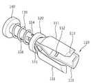
도 1은 본 발명의 실시 예에 따른 클립 건을 도시한 사시도이다.
도 2는 본 발명의 실시 예에 따른 클립을 도시한 사시도이다.
도 3은 본 발명의 제1 실시 예에 따른 클립몸체를 도시한 사시도이다.
도 4는 본 발명의 제2 실시 예에 따른 클립몸체를 도시한 단면도이다.
도 5a는 본 발명의 제1 실시 예에 따른 클립의 확개 상태를 도시한 사시도이다.
도 5b는 본 발명의 제1 실시 예에 따른 클립의 조임 상태를 도시한 사시도이다.
도 6a 내지 6c는 본 발명에 따른 클립 건의 동작 단계를 도시한 사시도이다.
도 7은 본 발명의 실시 예에 따른 클립카트리지를 도시한 사시도이다.1 is a perspective view showing a clip gun according to an embodiment of the present invention.
2 is a perspective view showing a clip according to an embodiment of the present invention.
3 is a perspective view showing the clip body according to the first embodiment of the present invention.
4 is a cross-sectional view showing a clip body according to a second embodiment of the present invention.
5A is a perspective view illustrating an expanded state of a clip according to a first embodiment of the present invention.
5B is a perspective view illustrating a tightening state of a clip according to a first embodiment of the present invention.
6a to 6c are perspective views showing the operation steps of the clip gun according to the present invention.
7 is a perspective view illustrating a clip cartridge according to an embodiment of the present invention.
이하 첨부된 도면을 참조하여 본 발명의 실시 예를 상세히 설명한다. 그러나 본 발명은 이하에서 개시되는 실시 예에 한정되는 것이 아니라 다양한 형태로 구현될 수 있으며, 단지 본 실시 예는 본 발명의 개시가 완전하도록 하며, 통상의 지식을 가진 자에게 발명의 범주를 완전하게 알려주기 위해 제공되는 것이다. 도면에서의 요소의 형상 등은 보다 명확한 설명을 위하여 과장되게 표현된 부분이 있을 수 있으며, 도면 상에서 동일 부호로 표시된 요소는 동일 요소를 의미한다.
Hereinafter, exemplary embodiments of the present invention will be described in detail with reference to the accompanying drawings. However, the present invention is not limited to the embodiments disclosed below, but can be implemented in various forms, only this embodiment to complete the disclosure of the present invention, to those skilled in the art to the full scope of the invention It is provided to inform you. The shape and the like of the elements in the drawings may be exaggerated for clarity, and the same reference numerals denote the same elements in the drawings.
도 1은 본 발명의 실시 예에 따른 클립 건을 도시한 사시도이다.1 is a perspective view showing a clip gun according to an embodiment of the present invention.
도 1에 도시된 바와 같이 본 발명의 실시 예에 따른 클립 건(1)은 클립(100)과, 클립(100)이 적재되는 격납관(10)과, 일측이 클립(100) 후미와 탈착 가능하게 결합되어 클립(100)을 격납관(10) 밖으로 밀어낼 수 있는 클립파지부(22)를 구비한 조작부(20)를 포함한다.As shown in FIG. 1, the
클립(100)과 클립파지부(22)에 대한 자세한 사항은 후술하고, 클립 건(1)의 다른 구성 요소들에 대해 설명한다.Details of the
격납관(10)은 내부에 클립(100)을 적재할 수 있는 공간이 구비된 튜브일 수 있다. 격납관(10)은 환자의 신체 내로 삽입되는 구성 요소로서, 구강 또는 항문을 통해 체내로 삽입되는 내시경 채널과 같은 삽입관을 따라 투입된다. 따라서 신체 내의 굴곡을 따라 격납관(10)이 용이하게 진입되도록, 격납관(10)은 휘어질 수 있게 형성됨이 바람직하다. 격납관(10) 내에는 복수 개의 클립(100)들이 순차적으로 연사될 수 있도록 일렬로 적재될 수 있다.The
격납관(10)의 일단에는 적재된 클립(100)들이 격납관(10) 외부로 토출될 수 있도록 개구된 출구가 형성된다. 격납관(10)의 타측에는 클립(100)들이 순차적으로 연사되도록 클립(100)들을 밀어내는 조작부(20)가 구비된다.One end of the
조작부(20)는 격납관(10) 내에서 진퇴 가능하게 설치되며, 격납관(10) 내에 적재된 복수 개의 클립(100)들 중 최후에 토출되는 클립의 후미에 결합되는 클립파지부(22)와, 일단이 클립파지부(22)와 연결되어 격납관(10)의 타측으로 연장되는 조작와이어(23)와, 조작와이어(23)의 타단에 결합되는 푸쉬링(26), 그리고 격납관(10) 타측의 외측부에 설치되는 손잡이부(24)를 구비할 수 있다.The
조작와이어(23)는 클립파지부(22)와 푸쉬링(26) 사이에 위치하여 시술자가 푸쉬링(26)을 통해 클립파지부(22)의 진퇴를 제어하도록 구성될 수 있다. 따라서 조작와이어(23)는 푸쉬링(26)의 이동량을 클립파지부(22)에 정확히 전달할 수 있는 동시에, 격납관(10)이 휘어짐에 따라 같이 휘어지도록 형성됨이 바람직하다.The
푸쉬링(26)은 시술자가 손가락, 예를 들면 엄지손가락을 푸쉬링(26) 내측에 걸고 푸쉬링(26)을 밀거나 당겨 클립 건(1)을 조작할 수 있도록 한다. The
푸쉬링(26)의 일측에는 슬라이딩 바(25)가 구비될 수 있다. 슬라이딩 바(25)는 푸시링(26)과 일체로 형성되어 푸쉬링(26)의 진퇴 방향을 안내할 수 있다. 이 경우 슬라이딩 바(25)는 조작와이어(23)를 내부에 포함하도록 구비될 수 있으며, 또는 조작와이어(23)는 슬라이딩 바(25)의 일단에 결합될 수 있다.One side of the
격납관(10)의 외측부에 구비되는 손잡이부(24)는 시술자가 클립 건(1)을 파지할 수 있도록 구비되는 구성 요소로서, 시술자는 푸쉬링(26)에 걸친 손가락 이외의 다른 손가락 및 손바닥으로 손잡이부(24)를 감싸 파지할 수 있다.The
손잡이부(24)의 일측은 격납관(10)의 타측과 결합되고, 손잡이부(24)의 타측에는 슬라이딩 바(25)의 일측이 진퇴 가능하게 삽입될 수 있다. 손잡이부(24)는 슬라이딩 바(25)의 진퇴 방향을 가이드하도록 내부에 가이드 홈(미도시)이 구비될 수 있다.
One side of the
이하에서는 본 발명에 따른 클립 건으로 적용되는 클립에 대해 설명한다. 도 2는 본 발명의 실시 예에 따른 클립을 도시한 사시도이다.Hereinafter, a clip applied to the clip gun according to the present invention will be described. 2 is a perspective view showing a clip according to an embodiment of the present invention.
도 2에 도시된 바와 같이, 베이스부(140)와, 베이스부(140)에서 연장 설치되는 암(111)과 암(111)의 일단에 구비되어 대상체를 협지하는 파지조(113)를 구비하는 클립몸체(110)와, 암(111)을 조여 주는 조임부(120), 그리고 탄성력에 의해 조임부(120)를 이동시키는 탄성 부재(130)를 포함한다.As shown in FIG. 2, the
베이스부(140)는 원판형의 플레이트로 형성될 수 있다. 또는 후술할 경사면(115)의 내측에 안착될 수 있는 형상으로 형성될 수 있다.The
클립몸체(110)는 베이스부(140)의 일면으로부터 연장 설치되며, 연장부(116)의 일측에서 3개의 암(111)으로 분기될 수 있다. 또는 베이스부(140)의 일면으로부터 3개의 암(111)이 각각 연장되도록 형성될 수도 있다. 상기 암(111)은 2개 이상으로 분기되어 대상체를 협지할 수 있도록 구비될 수 있다.The
암(111)은 자가확개성을 갖도록 형성된다. 즉 3개의 암(111)은 외부에서 아무런 힘이 가해지지 않는 경우 서로 벌어져 확개된다.(도 5a 참조)The
도 2에 도시된 바와 같이, 각 암(111)의 일단에는 대상체를 협지하는 파지조(113)가 구비된다. 암(111)이 대상체가 없이 조여질 때는 파지조(113)의 첨단들이 한 점에 모일 수 있도록, 파지조(113)는 암(111)의 연장 방향에 대해 대략 수직 내측으로 구비될 수 있다. 각 파지조(113)는 삼각형 또는 부채꼴 형상으로 형성되어, 대상체의 클리핑 시 인접하는 파지조(113)의 간섭이 방지되도록 구성될 수 있다.As shown in FIG. 2, one end of each
도 2에 도시된 바와 같이, 암(111)의 타측과 베이스부(140) 사이에는 조임부(120)가 구비될 수 있다. 조임부(120)는 환형 부재가 이용될 수 있으며, 암(111)의 측부를 포위하며 이동 가능하게 설치된다. 조임부(120)가 암(111)의 타측에서 일측 방향(이하, 일방향)으로 이동함에 따라 암(111)의 자가확개력을 억제하며 암(111)을 조여 파지조(113)가 대상체를 협지할 수 있도록 한다.As shown in FIG. 2, a tightening
또한 암(111)의 내측에는, 복수 개의 클립(100)들이 적재되는 경우에 대비하여, 전방에 위치한 클립(100)의 베이스부(140)의 타측이 지지될 수 있는 지지턱(112)이 구비될 수 있다. 또는 후술할 경사부(115)의 내측이 지지턱의 역할을 수행할 수 있다.In addition, the
한편 조임부(120)와 베이스부(140) 사이에는 탄성 부재(130)가 구비된다. 탄성 부재(130)는 연장부(116)의 둘레에 배치되며, 일단이 조임부(120)의 단부와 접촉하고, 타단이 베이스부(140)의 일측에 고정되도록 설치될 수 있다.Meanwhile, an
탄성 부재(130)는 압축된 상태에서 압축이 해제되며 탄성력에 의해 조임부(120)를 일방향으로 이동시킨다. 또한 파지조(113)가 대상체를 협지한 상태에서 암(111)의 자가확개력과 조임부(120)에 의한 자가확개억제력이 평형이 되도록 조임부(120)를 탄성지지할 수 있다. 도 2에 도시된 바와 같이, 탄성 부재(130)로는 나선 스프링이 이용될 수 있으나, 이에 한정되지 않고 압축 후 팽창하여 조임부(120)를 이동시키고 탄성지지할 수 있는 탄성력이 있는 부재가 다양하게 사용될 수 있다.
The
이하에서는 본 발명의 실시 예에 따른 클립의 클립몸체에 대해 구체적으로 설명한다. 도 3은 본 발명의 제1 실시 예에 따른 클립몸체를 도시한 사시도이다.Hereinafter will be described in detail with respect to the clip body of the clip according to an embodiment of the present invention. 3 is a perspective view showing the clip body according to the first embodiment of the present invention.
도 3에 도시된 바와 같이, 암(111)의 타측에는 암(111)이 외측방으로 절곡되어 형성되는 경사부(115)가 구비될 수 있다. 경사부(115)의 최대 외경은 조임부(120)의 내경 또는 최대 내경보다 크게 형성되어 조임부(120)의 일방향 이동을 제한하고, 동시에 조임부(120)가 경사부(115)에 밀착되어 암(111)의 자가 확개를 억제하며 암(111)을 조이도록 한다.As shown in FIG. 3, the other side of the
도시되진 않았지만, 도 3에 도시된 바와 달리, 경사부(115)는 단차부로 형성되어 조임부(120)의 일방향 이동을 저지하고, 암(111)을 조이도록 구성될 수도 있다.Although not shown, unlike in FIG. 3, the
한편, 도 3에 도시된 바와 같이 클립몸체(110)의 타측에는 걸림턱(114)이 구비될 수 있다. 걸림턱(114)은 상기 경사부(115)에서 암(111)의 타측 방향으로 이격된 위치에 암(111)의 외측으로 돌출 형성될 수 있다.On the other hand, as shown in Figure 3 the other side of the
걸림턱(114)은 일측에 단차턱(1142)이 형성되고, 타측에는 경사면(1141)이 형성되어, 조임부(120)가 탄성 부재(130)에 의해 일방향으로 이동할 때에는 경사면(1141)을 넘을 수 있지만, 조임부(120)가 경사면(1141)의 끝단에 형성된 단차턱(1142)을 지나치면 단차턱(1142)에 의해 반대 방향으로 이동할 수 없도록 구성될 수 있다.The latching
또한 조임부(120)의 내경이 일방향으로 확대되도록 하여 걸림턱(114)의 경사면(1141)을 따라 일방향으로 이동할 때에는 용이하게 진행되나, 반대 방향으로 이동할 때에는 단차턱(1142)에 쉽게 걸리도록 할 수 있다.In addition, the inner diameter of the tightening
걸림턱(114)은 조임부(120)의 타단이 단차턱(1142)에 의해 지지될 수 있도록 형성됨이 바람직하다. 걸림턱(114)은 암(111)의 자가확개력 또는 외부의 힘에 의해 조임부(120)가 일방향의 반대 방향으로 후퇴하는 것을 방지하여 클립(100)이 대상체를 견고하게 클리핑할 수 있도록 한다.
The locking
이하에서는 본 발명의 제2 실시 예에 따른 클립몸체에 대해 설명한다.Hereinafter, a clip body according to a second embodiment of the present invention will be described.
설명의 편의를 위하여 제1 실시 예와 공통되는 부분은 동일한 요소 부호를 사용하고 설명을 생략한다. 도 4는 본 발명의 제2 실시 예에 따른 클립몸체를 도시한 단면도이다.For convenience of description, parts common to those of the first embodiment use the same element codes and description thereof will be omitted. 4 is a cross-sectional view showing a clip body according to a second embodiment of the present invention.
본 발명의 제1 실시 예에 따른 클립몸체(110)는 클립몸체(110)에 구비된 걸림턱(114)이 고정식으로 항상 돌출되어 있도록 구비되나, 본 발명의 제2 실시 예에 따른 클립몸체(210)는 클립몸체(210)에 구비된 걸림턱(214)이 출몰식으로 구비된다.The
도 4에 도시된 바와 같이, 걸림턱(214)은 클립몸체(210)의 내측으로 회동하며 출몰 가능하게 설치될 수 있다. 걸림턱(214)은 클립몸체(210)의 일부를 'ㄷ'자 형상으로 잘라 클립몸체(210)와 연결된 부분을 외측방향으로 비스듬히 절곡하여 경사면(2141)을 형성하고, 경사면(2141)의 일측을 클립몸체(210)를 향해 절곡하여 단차턱(2142)을 형성함으로 구비할 수 있다. 걸림턱(214)에 외력이 작용하지 않는 경우 걸림턱(214)은 클립몸체(210)의 외측으로 돌출되어 위치하도록 형성됨이 바람직하다.As illustrated in FIG. 4, the locking
따라서, 조임부(120)가 탄성 부재(130)의 탄성력에 의해 일방향으로 이동할 때, 조임부(120)는 걸림턱(214)의 경사면(2141)을 따라 이동한다. 이 때, 걸림턱(214)은 조임부(120)에 의해 클립몸체(210)의 내측으로 인입되고, 조임부(120)가 경사면(2141)을 지나치면 걸림턱(214)이 자체 탄성력에 의해 돌출하고, 단차턱(2142)이 조임부(120)의 타단을 지지하여 조임부(120)가 반대 방향으로 이동하는 것을 제한한다.
Therefore, when the
한편, 클립(100)의 암(111)의 외측면이나 조임부(120)의 외측면, 또는 베이스부(140)의 타단면 등에는 광반응성 형광물질이 코팅될 수 있다. 수술 이전에 시술 부위를 표시하기 위해 체내 해당 부위에 클립(100)을 이용해 클리핑을 하는 경우, 클립(100)이 위치표시자의 기능을 수행할 수 있도록 하기 위한 것이다.Meanwhile, a photoreactive fluorescent substance may be coated on the outer surface of the
형광물질이 코팅된 클립(100)을 환자의 체내에 클리핑한 후, 형광물질이 반응하는 특정 파장 대역을 갖는 광원을 조사하면 형광물질이 반응하여 신체 내에 클리핑한 클립의 위치를 용이하고 정확하게 파악할 수 있고, 따라서 해당 부위에 대한 정확한 시술이 가능하게 된다.
Clip the fluorescent material coated
이하에서는 본 발명의 실시 예에 따른 클립의 동작에 대해 설명한다.Hereinafter will be described the operation of the clip according to an embodiment of the present invention.
도 5a는 본 발명의 제1 실시 예에 따른 클립의 확개 상태를 도시한 사시도이고, 도 5b는 본 발명의 제1 실시 예에 따른 클립의 조임 상태를 도시한 사시도이다.5A is a perspective view illustrating an expanded state of a clip according to a first embodiment of the present invention, and FIG. 5B is a perspective view illustrating a tightened state of a clip according to a first embodiment of the present invention.
도 5a에 도시된 바와 같이, 탄성 부재(130)가 압축되고 조임부(120)가 연장부(116) 주변에 위치하면, 암(111)은 자가확개성에 의해 확개된 채 유지된다. 탄성부재(130)를 압축하는 힘이 사라지고 탄성 부재(130)의 압축이 해제되면 탄성 부재(130)의 탄성력에 의해 조임부(120)가 일방향으로 이동한다.As shown in FIG. 5A, when the
조임부(120)는 일방향으로 이동하며, 암(111)의 자가확개력을 억제하면서 암(111)을 조인다. 도 5b에 도시된 바와 같이, 조임부(120)가 경사부(115)에 밀착되면 조임부(120)는 일방향 진행을 멈추고 파지조(113)가 대상체를 협지하여 클리핑한 상태를 유지하게 한다.The tightening
또한 조임부(120)는 일방향으로 이동하며, 걸림턱(114)의 타측에 형성된 경사면(1141)을 지나고 조임부(120)가 걸림턱(114)을 지나치면 걸림턱(114)의 일측에 형성된 단차턱(1142)에 의해 일방향의 반대 방향으로 이동하는 것이 제한된다.In addition, the tightening
걸림턱(214)이 클립몸체(210)의 내측으로 회동하며 출몰 가능하게 설치된 경우에는 조임부(120)가 경사면(2141)을 지날 때, 걸림턱(214)이 조임부(120)에 의해 클립몸체(210)의 내측으로 인입되고, 조임부(120)가 경사면(2141)을 지나치면 걸림턱(214)이 자체 탄성력에 의해 돌출하여 걸림턱(214)의 일측에 형성된 단차턱(2142)에 의해 일방향의 반대 방향으로 이동하는 것이 제한된다.
If the locking
이하에서는 본 발명의 실시 예에 따른 클립파지부에 대해 설명한다.Hereinafter, a clip holding part according to an embodiment of the present invention will be described.
도 1에 도시된 바와 같이, 클립파지부(22)는 클립(100)의 암(111)과 유사하게 3개의 암(21)을 포함할 수 있다.As shown in FIG. 1, the
암(21)은 클립(100)과 마찬가지로 자가확개성을 갖도록 형성되어 외부에서 아무런 힘이 가해지지 않는 경우 외측 방향으로 서로 벌어져 확개된다.Like the
암(21)의 일단에는 클립(100)의 탄성 부재(130)를 압축한 채, 조임부(120)의 일측을 지탱하는 파지조(27)가 구비되고, 파지조(27)는 클립의 것과 유사하게 암(21)의 연장 방향에 대해 대략 수직 내측으로 구비되며, 각 파지조(27)는 삼각형 또는 부채꼴 형상으로 형성될 수 있다.One end of the
또한 암(21)의 내측에는 클립의 베이스부(140)의 타측이 지지될 수 있는 지지턱(미도시)이 구비될 수 있다.In addition, a support jaw (not shown) may be provided inside the
한편, 암(21)의 타측에는 조작와이어(23)가 연결될 수 있다. 또는 암(21)의 타측과 조작와이어(23) 사이에 양자를 연결하는 연결부재(28)가 설치될 수도 있다.(도 7 참조)
Meanwhile, the
이하에서는 본 발명의 실시 예에 따른 클립 건의 동작에 대해 설명한다. 도 6a 내지 6c는 본 발명에 따른 클립 건의 동작 단계를 도시한 사시도이다.Hereinafter will be described the operation of the clip gun according to an embodiment of the present invention. 6a to 6c are perspective views showing the operation steps of the clip gun according to the present invention.
도 6a에 도시된 바와 같이, 격납관(10) 내에는 복수 개의 클립들(100a,100b)이 일렬로 적재될 수 있다. 이하에서는 인접하는 복수 개의 클립들(100a,100b) 중 전방(격납관의 출구 측)에 위치한 클립을 전방클립(100a)이라 하고, 후미(클립파지부 측)에 위치한 클립을 후미클립(100b)이라 한다.As shown in FIG. 6A, a plurality of
클립파지부(22)의 암(21)은 후미클립(100b)의 베이스부(140b) 타단을 암(21)의 내측에 형성된 지지턱(미도시)으로 지지하고, 후미클립(100b)의 탄성 부재(130b)와 조임부(120b)가 암(21)의 내측에 위치하도록 탄성 부재(130b)를 압축한 채로 클립파지부(22)의 파지조(27)가 후미클립(100b)의 조임부(120b) 일측을 지탱하도록 격납관(10) 내부에 적재된다.The
클립파지부(22)의 암(21)의 자가확개성은 격납관(10)의 내측벽에 의해 억제되어 파지조(27)가 조임부(120b)를 지탱할 수 있다.The self-expansion of the
전방클립(100a) 역시 이와 유사하게, 전방클립(100a)의 베이스부(140a) 타단이 후미클립(100b)의 암(111b)의 내측에 형성된 지지턱(112b)에 의해 지지되도록 위치되고, 전방클립(100a)의 탄성 부재(130a)와 조임부(120a)가 후미클립(100b)의 암(111b)의 내측에 위치하도록 전방클립(100a)의 탄성 부재(130a)를 압축한 채 후미클립(100b)의 파지조(113b)가 전방클립(100a)의 조임부(120a) 일측을 지탱하도록 격납관(10) 내부에 적재된다.Similarly, the
계속하여 동일한 방식으로 복수 개의 클립(100)이 격납관(10) 내부에 적재될 수 있다.Subsequently, a plurality of
복수 개의 클립(100)들이 격납관(10) 내에 적재된 후, 시술자는 격납관(10)을 출구 측부터 환자의 체내로 인입하여 격납관(10)의 출구를 최초 대상체에 가까이 위치시킨다.After the plurality of
이후, 시술자는 손잡이부(24)를 감싸쥔 후, 엄지손가락 또는 다른 손가락을 푸쉬링(26) 내측에 걸고 푸쉬링(26)을 밀어 조작와이어(23)가 클립파지부(22)를 격납관(10)의 출구 측으로 밀도록 조작한다.Then, after the operator wraps the
클립파지부(22)의 이동에 따라 클립파지부(22)의 전방에 적재된 복수 개의 클립(100)들이 동일한 방향으로 이동하게 되므로 푸쉬링(26)의 이동량으로 복수 개의 클립(100)들의 이동량을 제어할 수 있다.Since the plurality of
도 6b에 도시된 바와 같이, 푸쉬링(26)의 조작에 의해 전방클립(100a)의 암(111a)이 격납관(10)을 벗어나면 암(111a)의 자가확개성에 의해 암(111a)은 확개된다. 시술자는 확개된 암(111a)이 대상체를 둘러싸도록 클립(100a)을 위치시킨다.As shown in FIG. 6B, when the
이후, 도 6c에 도시된 바와 같이, 푸쉬링(26)을 더 밀어 후미클립(100b)의 암(111b)이 격납관(10)을 벗어나도록 클립들(100a, 100b)을 전진시키면, 후미클립(100b)의 암(111b)이 확개되어 후미클립(100b)의 암(111b)의 내측에 압축된 채로 위치하던 전방클립(100a)의 탄성 부재(130a)의 압축이 해제되며, 탄성 부재(130a)의 탄성력에 의해 전방클립(100a)의 조임부(120a)가 일방향으로 이동하게 된다.Then, as shown in Figure 6c, by pushing the
조임부(120a)는 일방향으로 이동하며, 암(111a)의 자가확개력을 억제하면서 암(111a)을 조인다. 그리고, 조임부(120a)가 경사부(115a)에 밀착되면 조임부(120a)는 일방향 진행을 멈추고 파지조(113a)가 대상체를 협지하여 클리핑한 상태를 유지하게 한다.The
동시에 조임부(120a)는 걸림턱(114)을 지나 걸림턱(114)의 일측에 형성된 단차턱(1142)에 의해 일방향의 반대 방향으로 이동하는 것이 제한된다.At the same time, the
이후, 클리핑할 다른 대상체에 후미클립(100b)을 위치시키고 상기와 동일한 방법으로 푸쉬링(26)을 조작하여 클리핑을 계속 할 수 있다. 계속하여 같은 방식으로 복수 개의 대상체들에 대해 복수 개의 클립(100)들을 연사하며 클리핑을 할 수 있다.
Thereafter, the
이하에서는 본 발명의 실시 예에 따른 복수 개의 클립들의 적재 방법에 대해 설명한다.Hereinafter, a method of loading a plurality of clips according to an embodiment of the present invention will be described.
복수 개의 클립들의 적재를 위해, 우선 푸쉬링(26)을 밀어 클립파지부(22)의 암(21)이 격납관(10)의 출구 밖으로 노출되도록 하여 클립파지부(22)의 암(21)이 자가확개성에 의해 확개되면, 후미클립(100b)의 탄성 부재(130b)를 압축하여 조임부(120b) 및 탄성 부재(130b)를 확개된 클립파지부(22)의 암(21)의 내측에 위치시킨 후, 푸쉬링(26)을 당겨 클립파지부(22)의 암(21)이 후미클립(100b)의 조임부(120b)를 지탱하며 격납관(10) 내부로 유입되도록 할 수 있다.To load the plurality of clips, first push the
이후, 유사한 방법으로 전방클립(100a)의 탄성 부재(130a)를 압축하여 조임부(120a) 및 탄성 부재(130a)를 확개된 후미클립(100b)의 암(111b)의 내측에 위치시킨 후, 푸쉬링(26)을 당겨 후미클립(100b)의 암(111b)이 전방클립(100a)의 조임부(120a)를 지탱하며 격납관(10) 내부로 유입되도록 할 수 있다.Thereafter, the
상기 동작을 반복하여 복수 개의 클립(100)들을 격납관(10) 내에 적재할 수 있다.By repeating the above operation, the plurality of
또는 복수 개의 클립(100)들이 미리 적재된 클립카트리지가 이용될 수도 있다. 도 7은 본 발명의 실시 예에 따른 클립카트리지를 도시한 사시도이다.Alternatively, a clip cartridge loaded with a plurality of
도 7에 도시된 바와 같이, 전방클립(100a)의 탄성 부재(130a)가 압축된 상태로 조임부(120a)와 함께 후미클립(100b)의 암(111b)의 내측에 위치되도록 적재된 복수 개의 클립(100)들과 클립파지부(22)가 포함된 클립카트리지(11)가 미리 준비되고, 클립카트리지(11)의 클립파지부(22) 측과 격납관(10)의 출구 측을 맞대어 놓은 후, 클립파지부(22)의 단부에 위치한 연결부재(28)에 조작와이어(23)를 연결하고 푸시링(26)을 당기는 것에 의해 클립카트리지(11) 내에 적재된 복수 개의 클립(100)들이 한 번에 격납관(10) 내로 이동되도록 구성될 수도 있다. 또는 클립카트리지(11)가 격납관(10) 출구 측에 연결되어 장착되도록 구성될 수도 있다.
As shown in FIG. 7, the plurality of
상기와 같은 구성 및 방법에 의해 본 발명에 따른 클립 건은 조작부가 클립을 밀어내는 동작만으로 대상체를 각각 타기팅하고 클리핑할 수 있으며, 복수 개의 클립들을 연속적으로 클리핑할 수 있어, 하나의 클립을 클리핑할 때마다 클립 건을 환자의 체내 밖으로 빼내어 새 클립을 장착한 후 다시 환자의 체내로 삽입하는 번거로움을 피할 수 있으므로, 시술 시간이 단축되며 시술자와 환자의 불편을 감소시킬 수 있다.
According to the configuration and method as described above, the clip gun according to the present invention can target and clip each object only by the operation of pushing the clip, and can clip a plurality of clips in succession to clip one clip. Each time the clip gun is pulled out of the patient's body to avoid the hassle of mounting a new clip and then inserting it back into the patient's body, reducing the procedure time and reducing the discomfort of the operator and patient.
앞에서 설명되고, 도면에 도시된 본 발명의 실시 예는, 본 발명의 기술적 사상을 한정하는 것으로 해석되어서는 안 된다. 본 발명의 보호범위는 청구범위에 기재된 사항에 의해서만 제한되고, 본 발명의 기술 분야에서 통상의 지식을 가진 자는 본 발명의 기술적 사상을 다양한 형태로 개량 변경하는 것이 가능하다. 따라서 이러한 개량 및 변경은 통상의 지식을 가진 자에게 자명한 것인 한 본 발명의 보호범위에 속하게 될 것이다.
The embodiments of the present invention described above and illustrated in the drawings should not be construed as limiting the technical idea of the present invention. The scope of protection of the present invention is limited only by the matters described in the claims, and those skilled in the art can change and change the technical idea of the present invention in various forms. Accordingly, such improvements and modifications will fall within the scope of the present invention as long as they are obvious to those skilled in the art.
1: 클립 건10: 격납관
11: 클립카트리지20: 조작부
21: 클립파지부의 암22: 클립파지부
23: 조작와이어24: 손잡이부
25: 슬라이딩 바26: 푸쉬링
27: 클립파지부의 파지조28: 연결부재
100: 클립110: 클립몸체
111: 클립의 암112: 지지턱
113: 클립의 파지조114: 걸림턱
115: 경사부116: 연장부
120: 조임부130: 탄성 부재
140: 베이스부1: clip gun 10: containment tube
11: Clip cartridge 20: control panel
21: Arm of the clip holding part 22: Clip holding part
23: operation wire 24: handle portion
25: sliding bar 26: push ring
27: holding gripping portion of the clip holding portion 28: connecting member
100: Clip 110: Clip body
111: arm of the clip 112: support jaw
113: Grip tank of the clip 114: Hanging jaw
115: inclined portion 116: extension portion
120: tightening unit 130: elastic member
140: base portion
Claims (33)
Translated fromKorean베이스부와,
상기 베이스부에서 연장되며, 외측으로 자가확개성(自家擴開性)을 갖고 내측에는 전방에 위치하는 전방클립의 상기 베이스부를 지지하는 지지턱이 형성된 복수 개의 암과,
상기 암의 일단에 구비되어 타깃을 협지하는 파지조(把持爪)와,
상기 복수 개의 암의 외측부를 포위하며 이동 가능하게 설치되어, 일방향으로 이동하며 상기 파지조가 상기 타깃을 협지할 수 있도록 상기 암을 조여 주는 조임부와,
상기 베이스부와 상기 조임부 사이에 구비되어, 탄성력에 의해 상기 조임부를 이동시키는 탄성 부재를 구비하는 클립; 및
상기 전방클립 및 상기 클립을 내부에 적재하되, 상기 전방클립은 상기 전방클립의 상기 탄성부재가 압축된 채, 상기 전방클립의 상기 베이스부가 상기 클립의 지지턱에 지지되고, 상기 전방클립의 상기 조임부가 상기 클립의 상기 파지조에 의해 지지되어 적재되는 격납관과,
상기 격납관 내에서 진퇴 가능하게 설치되며, 상기 클립의 상기 탄성 부재를 압축한 상태로 상기 클립의 상기 조임부의 일측을 지탱할 수 있으며, 자가확개성을 갖는 클립파지부를 구비하는 클립 건;을 포함하고,
상기 지지턱은 상기 암의 내측 방향으로 돌출 형성되는 것을 특징으로 하는 의료용 클립장치.
In the medical clip device for loading and clipping a plurality of clips,
With the base part,
A plurality of arms extending from the base portion, having a support jaw supporting the base portion of the front clip positioned at the front and having a self-expansion outward;
A gripping tank provided at one end of the arm and holding a target;
A fastening part surrounding the outer side of the plurality of arms and installed to be movable, moving in one direction and tightening the arm so that the gripping tank can clamp the target;
A clip provided between the base portion and the tightening portion and having an elastic member for moving the tightening portion by an elastic force; And
The front clip and the clip is loaded therein, wherein the front clip is the base member of the front clip is supported on the support jaw of the clip while the elastic member of the front clip is compressed, the tightening of the front clip A containment pipe additionally supported and loaded by the gripping tank of the clip;
A clip gun installed to be retractable in the containment pipe and capable of supporting one side of the fastening portion of the clip while compressing the elastic member of the clip, the clip gun having a clip holding portion having self-expansion; Including,
The support jaw is a medical clip device characterized in that the protrusion formed in the inner direction of the arm.
상기 클립파지부가 상기 클립을 상기 격납관의 출구 측으로 밀어냄에 따라, 상기 암이 상기 격납관을 벗어나며 자가확개성에 의해 확개되는 것을 특징으로 하는 의료용 클립장치.
The method of claim 1,
And the clip is pushed by the clip toward the outlet side of the containment tube, so that the arm escapes from the containment tube and is enlarged by self-expansion.
상기 암의 자가 확개 이후, 상기 클립파지부가 상기 클립을 더 밀어냄에 따라, 상기 클립파지부가 확개되고, 상기 탄성 부재의 압축이 해제되어 상기 탄성력에 의해 상기 조임부가 이동하며 확개된 상기 암을 조이는 것을 특징으로 하는 의료용 클립장치.
The method of claim 2,
After self-expansion of the arm, as the clip gripping portion pushes the clip further, the clip gripping portion is expanded, and the compression of the elastic member is released to move the tightening portion by the elastic force and tighten the expanded arm. Medical clip device, characterized in that.
상기 격납관은 탈착 가능한 클립카트리지를 구비하며, 복수 개의 상기 클립들은 상기 클립카트리지 내에 적재되는 것을 특징으로 하는 의료용 클립장치.
The method of claim 1,
The containment pipe is provided with a removable clip cartridge, a plurality of the clip is a medical clip device, characterized in that is loaded in the clip cartridge.
상기 클립파지부와 연결되며 상기 격납관의 외부로 연장되어, 상기 격납관의 외부에서 상기 클립파지부의 진퇴를 제어하는 조작와이어를 더 구비하는 것을 특징으로 하는 의료용 클립장치.
The method of claim 1, wherein the clip gun,
And a control wire connected to the clip holding part and extending to the outside of the containment pipe to control the advance and retreat of the clip holding part from the outside of the containment pipe.
상기 클립 건은 상기 조작와이어를 밀고 당기는 푸쉬링을 더 구비하는 것을 특징으로 하는 의료용 클립장치.
10. The method of claim 9,
The clip gun is a medical clip device further comprising a push ring for pushing and pulling the operation wire.
상기 클립 건은 상기 격납관의 외측부에 설치되는 손잡이부를 더 포함하는 것을 특징으로 하는 의료용 클립장치.
The method of claim 1,
The clip gun is a medical clip device, characterized in that it further comprises a handle installed on the outer portion of the containment tube.
상기 암에는, 상기 조임부의 일방향 이동을 제한함과 동시에 상기 조임부가 상기 암의 자가 확개를 억제할 수 있도록 경사부가 형성된 것을 특징으로 하는 의료용 클립장치.
The method of claim 1,
The arm, medical clip device characterized in that the inclined portion is formed so as to limit the one-way movement of the tightening portion and the tightening portion to suppress the self-expansion of the arm.
상기 암의 외측에는 상기 조임부가 상기 암의 자가확개성에 대한 억제력을 유지할 수 있도록 걸림턱이 구비된 것을 특징으로 하는 의료용 클립장치.
The method of claim 1,
Medical clip device, characterized in that the locking jaw is provided on the outer side of the arm so that the tightening portion can maintain the suppression force on the self-expansion of the arm.
상기 걸림턱은 일측에 단차턱이 형성되고, 타측에 경사면이 형성된 것을 특징으로 하는 의료용 클립장치.
The method of claim 13,
The locking jaw is a medical clip device, characterized in that the stepped jaw is formed on one side, the inclined surface on the other side.
상기 걸림턱은 상기 암의 내측으로 회동하며 출몰 가능하게 설치되어, 상기 조임부가 상기 걸림턱을 지날 때는 상기 암의 내측으로 인입되고, 상기 조임부가 상기 걸림턱을 지나치면 상기 걸림턱의 일단이 돌출되어 상기 조임부를 지지하는 것을 특징으로 하는 의료용 클립장치.
15. The method of claim 14,
The locking jaw rotates inwardly of the arm and is installed to be retracted. When the tightening part passes through the locking jaw, the locking jaw is introduced into the arm. When the tightening part passes the locking jaw, one end of the locking jaw protrudes. Medical clip device characterized in that for supporting the tightening.
상기 탄성 부재는 나선 스프링인 것을 특징으로 하는 의료용 클립장치.
The method of claim 1,
The medical clip device, characterized in that the elastic member is a spiral spring.
상기 조임부의 외측면과 상기 암의 외측면 중 적어도 하나 이상에는 광반응성 형광물질이 코팅된 것을 특징으로 하는 의료용 클립장치.
The method according to any one of claims 1 to 3, 8 to 15, and 17,
Medical clip device, characterized in that the photoreactive fluorescent material is coated on at least one of the outer surface of the tightening portion and the outer surface of the arm.
베이스부;
상기 베이스부에서 연장 설치되며, 외측으로 자가확개성을 갖고, 내측에는 전방에 적재되는 클립의 상기 베이스부를 지지하는 지지턱이 형성된 복수 개의 암;
상기 암의 일단에 구비되어 대상체를 협지하는 파지조;
상기 복수 개의 암의 외측부를 포위하며 이동 가능하게 설치되어, 일방향으로 이동하며 상기 파지조가 상기 대상체를 협지할 수 있도록 상기 암을 조여 주는 조임부; 및
상기 베이스부와 상기 조임부 사이에 위치하며, 탄성력에 의해 상기 조임부를 이동시키는 탄성 부재;를 포함하고,
상기 지지턱은 상기 암의 내측 방향으로 돌출 형성되는 것을 특징으로 하는 의료용 클립.
In the medical clip loaded in the clip gun for loading and clipping a plurality of medical clips,
A base portion;
A plurality of arms extending from the base and having a self-expansion toward the outside, and having a support jaw supporting the base of the clip loaded at the front;
A gripping tank provided at one end of the cancer and holding the object;
A tightening part surrounding the outer side of the plurality of arms and installed to be movable, moving in one direction and tightening the arm so that the gripping jaw can pinch the object; And
And an elastic member positioned between the base portion and the tightening portion to move the tightening portion by an elastic force.
The support jaw is a medical clip, characterized in that protruding in the inner direction of the arm.
상기 암에는, 상기 조임부의 일방향 이동을 제한함과 동시에 상기 조임부에 의해 상기 암의 자가 확개를 억제할 수 있도록 경사부가 형성된 것을 특징으로 하는 의료용 클립.
26. The method of claim 25,
The medical clip, characterized in that the inclined portion is formed so as to limit the one-way movement of the tightening portion and to suppress the self-expansion of the arm by the tightening portion.
상기 탄성 부재는, 일단이 상기 조임부의 단부에 지지되고, 타단이 상기 베이스부의 일측에 지지되도록 구비되는 나선 스프링인 것을 특징으로 하는 의료용 클립.
26. The method of claim 25,
The elastic member is a medical clip, characterized in that the spiral spring is provided so that one end is supported on the end of the tightening portion, the other end is supported on one side of the base portion.
상기 암의 외측에는 상기 조임부가 상기 암의 자가확개성에 대한 억제력을 유지할 수 있도록 걸림턱이 구비된 것을 특징으로 하는 의료용 클립.
26. The method of claim 25,
The outer side of the arm is a medical clip, characterized in that the locking jaw is provided so that the tightening portion can maintain the suppression force against the self-expansion of the arm.
상기 걸림턱은 일측에 단차턱이 형성되고, 타측에 경사면이 형성된 것을 특징으로 하는 의료용 클립.
29. The method of claim 28,
The locking jaw is a medical clip, characterized in that the stepped jaw is formed on one side, the inclined surface on the other side.
상기 걸림턱은 상기 암의 내측으로 회동하며 출몰 가능하게 설치되어, 상기 조임부가 상기 걸림턱을 지날 때는 상기 암의 내측으로 인입되고, 상기 조임부가 상기 걸림턱을 지나치면 상기 걸림턱의 일단이 돌출되어 상기 조임부를 지지하는 것을 특징으로 하는 의료용 클립.
30. The method of claim 29,
The locking jaw rotates inwardly of the arm and is installed to be retracted. When the tightening part passes through the locking jaw, the locking jaw is introduced into the arm. When the tightening part passes the locking jaw, one end of the locking jaw protrudes. Medical clip, characterized in that for supporting the tightening.
상기 조임부의 외측면과 상기 암의 외측면 중 적어도 하나 이상에는 광반응성 형광물질이 코팅된 것을 특징으로 하는 의료용 클립.
The method according to any one of claims 25 to 30,
Medical clip characterized in that the photoreactive fluorescent material is coated on at least one of the outer surface of the tightening portion and the outer surface of the arm.
Priority Applications (1)
| Application Number | Priority Date | Filing Date | Title |
|---|---|---|---|
| KR1020110057878AKR101201083B1 (en) | 2011-06-15 | 2011-06-15 | Medical Multiple Clips, Clip Gun applying the same, Clipping Method using the same |
Applications Claiming Priority (1)
| Application Number | Priority Date | Filing Date | Title |
|---|---|---|---|
| KR1020110057878AKR101201083B1 (en) | 2011-06-15 | 2011-06-15 | Medical Multiple Clips, Clip Gun applying the same, Clipping Method using the same |
Publications (1)
| Publication Number | Publication Date |
|---|---|
| KR101201083B1true KR101201083B1 (en) | 2012-11-13 |
Family
ID=47564620
Family Applications (1)
| Application Number | Title | Priority Date | Filing Date |
|---|---|---|---|
| KR1020110057878AExpired - Fee RelatedKR101201083B1 (en) | 2011-06-15 | 2011-06-15 | Medical Multiple Clips, Clip Gun applying the same, Clipping Method using the same |
Country Status (1)
| Country | Link |
|---|---|
| KR (1) | KR101201083B1 (en) |
Cited By (5)
| Publication number | Priority date | Publication date | Assignee | Title |
|---|---|---|---|---|
| KR101533915B1 (en)* | 2014-02-21 | 2015-07-03 | 강태섭 | Multi clip gun for endoscopic treatment |
| EP3643254A4 (en)* | 2017-06-21 | 2020-04-29 | Fujifilm Corporation | DISCONNECTING TOOL |
| CN111616768A (en)* | 2020-06-16 | 2020-09-04 | 苏州市倍咏医疗科技有限公司 | Multiple-type clamping device and operation method |
| KR20200134921A (en) | 2019-05-24 | 2020-12-02 | 주식회사 코스코메디칼 | Medical Florescent Marker |
| CN119908853A (en)* | 2025-04-01 | 2025-05-02 | 中国科学院长春光学精密机械与物理研究所 | A visual umbrella-shaped positioning device for tiny lesions |
Citations (3)
| Publication number | Priority date | Publication date | Assignee | Title |
|---|---|---|---|---|
| JP3568280B2 (en) | 1995-07-12 | 2004-09-22 | 富士写真フイルム株式会社 | Surgical operation support system |
| US20080306492A1 (en) | 2007-06-08 | 2008-12-11 | Hoya Corporation | Clipping instrument for an endoscopic surgical device |
| US20100160935A1 (en) | 2008-12-19 | 2010-06-24 | Wilson-Cook Medical Inc. | Clip devices and methods of delivery and deployment |
- 2011
- 2011-06-15KRKR1020110057878Apatent/KR101201083B1/ennot_activeExpired - Fee Related
Patent Citations (3)
| Publication number | Priority date | Publication date | Assignee | Title |
|---|---|---|---|---|
| JP3568280B2 (en) | 1995-07-12 | 2004-09-22 | 富士写真フイルム株式会社 | Surgical operation support system |
| US20080306492A1 (en) | 2007-06-08 | 2008-12-11 | Hoya Corporation | Clipping instrument for an endoscopic surgical device |
| US20100160935A1 (en) | 2008-12-19 | 2010-06-24 | Wilson-Cook Medical Inc. | Clip devices and methods of delivery and deployment |
Non-Patent Citations (1)
| Title |
|---|
| 대한방사선중앙학회지 Vol. 24, No. 3, pp.192-200, 2006 |
Cited By (6)
| Publication number | Priority date | Publication date | Assignee | Title |
|---|---|---|---|---|
| KR101533915B1 (en)* | 2014-02-21 | 2015-07-03 | 강태섭 | Multi clip gun for endoscopic treatment |
| EP3643254A4 (en)* | 2017-06-21 | 2020-04-29 | Fujifilm Corporation | DISCONNECTING TOOL |
| US11141167B2 (en) | 2017-06-21 | 2021-10-12 | Fujifilm Corporation | Clip treatment tool |
| KR20200134921A (en) | 2019-05-24 | 2020-12-02 | 주식회사 코스코메디칼 | Medical Florescent Marker |
| CN111616768A (en)* | 2020-06-16 | 2020-09-04 | 苏州市倍咏医疗科技有限公司 | Multiple-type clamping device and operation method |
| CN119908853A (en)* | 2025-04-01 | 2025-05-02 | 中国科学院长春光学精密机械与物理研究所 | A visual umbrella-shaped positioning device for tiny lesions |
Similar Documents
| Publication | Publication Date | Title |
|---|---|---|
| US20230293177A1 (en) | Hemostasis reloadable clip release mechanism | |
| KR101201083B1 (en) | Medical Multiple Clips, Clip Gun applying the same, Clipping Method using the same | |
| AU2007229334B2 (en) | Apparatus for applying surgical clips | |
| KR101283902B1 (en) | Clip applier configured to prevent clip fallout | |
| US8262678B2 (en) | Clip package for clip application apparatus | |
| US6991634B2 (en) | Clip device of endoscope | |
| CN115005921B (en) | Hemostatic reloadable clamping device with cannula engagement | |
| KR101283901B1 (en) | Clip applier with migrational resistance features | |
| RU2597771C2 (en) | Improved clip advancer | |
| JP2020518390A (en) | End operation device, end operation device, transportation device and assembly case | |
| CN111803167B (en) | Plugging device, plugging device locking system and locking method | |
| US20090318937A1 (en) | Clip coupling method and multiple clip package | |
| CN111616768B (en) | Multiple clamping device and operation method | |
| KR20190057557A (en) | Clipping device for endoscope | |
| US20090275959A1 (en) | Multiple clip device and multiple clip application apparatus | |
| JP5185977B2 (en) | Ligation device | |
| JP4591433B2 (en) | Clip device | |
| JP7303217B2 (en) | Ligating device and applicator | |
| JP4590371B2 (en) | Ligating device and endoscope system | |
| KR20190012017A (en) | A Clip Boom Having a Structure of Separating Pin | |
| JP7474890B2 (en) | Clip Systems and Applicators | |
| JP7183854B2 (en) | Endoscope clip device | |
| JP2010136820A (en) | Cylindrical member and repeating type clip treatment instrument | |
| CN115089256A (en) | A tourniquet and belt storage mechanism | |
| KR101685294B1 (en) | Clip applier |
Legal Events
| Date | Code | Title | Description |
|---|---|---|---|
| PA0109 | Patent application | St.27 status event code:A-0-1-A10-A12-nap-PA0109 | |
| A201 | Request for examination | ||
| A302 | Request for accelerated examination | ||
| PA0201 | Request for examination | St.27 status event code:A-1-2-D10-D11-exm-PA0201 | |
| PA0302 | Request for accelerated examination | St.27 status event code:A-1-2-D10-D17-exm-PA0302 St.27 status event code:A-1-2-D10-D16-exm-PA0302 | |
| D13-X000 | Search requested | St.27 status event code:A-1-2-D10-D13-srh-X000 | |
| D14-X000 | Search report completed | St.27 status event code:A-1-2-D10-D14-srh-X000 | |
| D14-X000 | Search report completed | St.27 status event code:A-1-2-D10-D14-srh-X000 | |
| D14-X000 | Search report completed | St.27 status event code:A-1-2-D10-D14-srh-X000 | |
| D14-X000 | Search report completed | St.27 status event code:A-1-2-D10-D14-srh-X000 | |
| D14-X000 | Search report completed | St.27 status event code:A-1-2-D10-D14-srh-X000 | |
| E902 | Notification of reason for refusal | ||
| PE0902 | Notice of grounds for rejection | St.27 status event code:A-1-2-D10-D21-exm-PE0902 | |
| T11-X000 | Administrative time limit extension requested | St.27 status event code:U-3-3-T10-T11-oth-X000 | |
| E13-X000 | Pre-grant limitation requested | St.27 status event code:A-2-3-E10-E13-lim-X000 | |
| P11-X000 | Amendment of application requested | St.27 status event code:A-2-2-P10-P11-nap-X000 | |
| P13-X000 | Application amended | St.27 status event code:A-2-2-P10-P13-nap-X000 | |
| E90F | Notification of reason for final refusal | ||
| PE0902 | Notice of grounds for rejection | St.27 status event code:A-1-2-D10-D21-exm-PE0902 | |
| R17-X000 | Change to representative recorded | St.27 status event code:A-3-3-R10-R17-oth-X000 | |
| E13-X000 | Pre-grant limitation requested | St.27 status event code:A-2-3-E10-E13-lim-X000 | |
| P11-X000 | Amendment of application requested | St.27 status event code:A-2-2-P10-P11-nap-X000 | |
| P13-X000 | Application amended | St.27 status event code:A-2-2-P10-P13-nap-X000 | |
| E701 | Decision to grant or registration of patent right | ||
| PE0701 | Decision of registration | St.27 status event code:A-1-2-D10-D22-exm-PE0701 | |
| GRNT | Written decision to grant | ||
| PR0701 | Registration of establishment | St.27 status event code:A-2-4-F10-F11-exm-PR0701 | |
| PR1002 | Payment of registration fee | St.27 status event code:A-2-2-U10-U11-oth-PR1002 Fee payment year number:1 | |
| PG1601 | Publication of registration | St.27 status event code:A-4-4-Q10-Q13-nap-PG1601 | |
| PR1001 | Payment of annual fee | St.27 status event code:A-4-4-U10-U11-oth-PR1001 Fee payment year number:4 | |
| P22-X000 | Classification modified | St.27 status event code:A-4-4-P10-P22-nap-X000 | |
| FPAY | Annual fee payment | Payment date:20161028 Year of fee payment:5 | |
| PR1001 | Payment of annual fee | St.27 status event code:A-4-4-U10-U11-oth-PR1001 Fee payment year number:5 | |
| P22-X000 | Classification modified | St.27 status event code:A-4-4-P10-P22-nap-X000 | |
| FPAY | Annual fee payment | Payment date:20170928 Year of fee payment:6 | |
| PR1001 | Payment of annual fee | St.27 status event code:A-4-4-U10-U11-oth-PR1001 Fee payment year number:6 | |
| PR1001 | Payment of annual fee | St.27 status event code:A-4-4-U10-U11-oth-PR1001 Fee payment year number:7 | |
| P22-X000 | Classification modified | St.27 status event code:A-4-4-P10-P22-nap-X000 | |
| FPAY | Annual fee payment | Payment date:20191029 Year of fee payment:8 | |
| PR1001 | Payment of annual fee | St.27 status event code:A-4-4-U10-U11-oth-PR1001 Fee payment year number:8 | |
| PR1001 | Payment of annual fee | St.27 status event code:A-4-4-U10-U11-oth-PR1001 Fee payment year number:9 | |
| PR1001 | Payment of annual fee | St.27 status event code:A-4-4-U10-U11-oth-PR1001 Fee payment year number:10 | |
| PR1001 | Payment of annual fee | St.27 status event code:A-4-4-U10-U11-oth-PR1001 Fee payment year number:11 | |
| PC1903 | Unpaid annual fee | St.27 status event code:A-4-4-U10-U13-oth-PC1903 Not in force date:20231108 Payment event data comment text:Termination Category : DEFAULT_OF_REGISTRATION_FEE | |
| PC1903 | Unpaid annual fee | St.27 status event code:N-4-6-H10-H13-oth-PC1903 Ip right cessation event data comment text:Termination Category : DEFAULT_OF_REGISTRATION_FEE Not in force date:20231108 |