KR101199667B1 - Flat spring of voice coil motor and assembly method of voice coil motor using the same - Google Patents
Flat spring of voice coil motor and assembly method of voice coil motor using the sameDownload PDFInfo
- Publication number
- KR101199667B1 KR101199667B1KR1020090096572AKR20090096572AKR101199667B1KR 101199667 B1KR101199667 B1KR 101199667B1KR 1020090096572 AKR1020090096572 AKR 1020090096572AKR 20090096572 AKR20090096572 AKR 20090096572AKR 101199667 B1KR101199667 B1KR 101199667B1
- Authority
- KR
- South Korea
- Prior art keywords
- leaf spring
- bobbin
- voice coil
- coil motor
- frame
- Prior art date
- Legal status (The legal status is an assumption and is not a legal conclusion. Google has not performed a legal analysis and makes no representation as to the accuracy of the status listed.)
- Active
Links
- 238000000034methodMethods0.000titleclaimsdescription14
- 230000003287optical effectEffects0.000description5
- 238000004806packaging method and processMethods0.000description3
- 125000006850spacer groupChemical group0.000description3
- 239000010409thin filmSubstances0.000description3
- RYGMFSIKBFXOCR-UHFFFAOYSA-NCopperChemical compound[Cu]RYGMFSIKBFXOCR-UHFFFAOYSA-N0.000description2
- 229910052782aluminiumInorganic materials0.000description2
- XAGFODPZIPBFFR-UHFFFAOYSA-NaluminiumChemical compound[Al]XAGFODPZIPBFFR-UHFFFAOYSA-N0.000description2
- 238000005520cutting processMethods0.000description2
- 230000007547defectEffects0.000description2
- 229910000828alnicoInorganic materials0.000description1
- 239000002131composite materialSubstances0.000description1
- 229910052802copperInorganic materials0.000description1
- 239000010949copperSubstances0.000description1
- 238000006073displacement reactionMethods0.000description1
- 238000005530etchingMethods0.000description1
- 239000000463materialSubstances0.000description1
- 239000007769metal materialSubstances0.000description1
- 238000012986modificationMethods0.000description1
- 230000004048modificationEffects0.000description1
- 229910052761rare earth metalInorganic materials0.000description1
- 150000002910rare earth metalsChemical class0.000description1
- 238000011084recoveryMethods0.000description1
- 230000035945sensitivityEffects0.000description1
- 229910000859α-FeInorganic materials0.000description1
Images


Classifications
- H—ELECTRICITY
- H02—GENERATION; CONVERSION OR DISTRIBUTION OF ELECTRIC POWER
- H02K—DYNAMO-ELECTRIC MACHINES
- H02K41/00—Propulsion systems in which a rigid body is moved along a path due to dynamo-electric interaction between the body and a magnetic field travelling along the path
- H02K41/02—Linear motors; Sectional motors
- H02K41/035—DC motors; Unipolar motors
- H02K41/0352—Unipolar motors
- H02K41/0354—Lorentz force motors, e.g. voice coil motors
- H02K41/0356—Lorentz force motors, e.g. voice coil motors moving along a straight path
- G—PHYSICS
- G02—OPTICS
- G02B—OPTICAL ELEMENTS, SYSTEMS OR APPARATUS
- G02B7/00—Mountings, adjusting means, or light-tight connections, for optical elements
- G02B7/02—Mountings, adjusting means, or light-tight connections, for optical elements for lenses
- G02B7/026—Mountings, adjusting means, or light-tight connections, for optical elements for lenses using retaining rings or springs
- G—PHYSICS
- G02—OPTICS
- G02B—OPTICAL ELEMENTS, SYSTEMS OR APPARATUS
- G02B7/00—Mountings, adjusting means, or light-tight connections, for optical elements
- G02B7/02—Mountings, adjusting means, or light-tight connections, for optical elements for lenses
- G02B7/04—Mountings, adjusting means, or light-tight connections, for optical elements for lenses with mechanism for focusing or varying magnification
- G02B7/09—Mountings, adjusting means, or light-tight connections, for optical elements for lenses with mechanism for focusing or varying magnification adapted for automatic focusing or varying magnification
- G—PHYSICS
- G03—PHOTOGRAPHY; CINEMATOGRAPHY; ANALOGOUS TECHNIQUES USING WAVES OTHER THAN OPTICAL WAVES; ELECTROGRAPHY; HOLOGRAPHY
- G03B—APPARATUS OR ARRANGEMENTS FOR TAKING PHOTOGRAPHS OR FOR PROJECTING OR VIEWING THEM; APPARATUS OR ARRANGEMENTS EMPLOYING ANALOGOUS TECHNIQUES USING WAVES OTHER THAN OPTICAL WAVES; ACCESSORIES THEREFOR
- G03B13/00—Viewfinders; Focusing aids for cameras; Means for focusing for cameras; Autofocus systems for cameras
- G03B13/32—Means for focusing
- G03B13/34—Power focusing
- G—PHYSICS
- G03—PHOTOGRAPHY; CINEMATOGRAPHY; ANALOGOUS TECHNIQUES USING WAVES OTHER THAN OPTICAL WAVES; ELECTROGRAPHY; HOLOGRAPHY
- G03B—APPARATUS OR ARRANGEMENTS FOR TAKING PHOTOGRAPHS OR FOR PROJECTING OR VIEWING THEM; APPARATUS OR ARRANGEMENTS EMPLOYING ANALOGOUS TECHNIQUES USING WAVES OTHER THAN OPTICAL WAVES; ACCESSORIES THEREFOR
- G03B3/00—Focusing arrangements of general interest for cameras, projectors or printers
- G03B3/10—Power-operated focusing
- H—ELECTRICITY
- H02—GENERATION; CONVERSION OR DISTRIBUTION OF ELECTRIC POWER
- H02K—DYNAMO-ELECTRIC MACHINES
- H02K33/00—Motors with reciprocating, oscillating or vibrating magnet, armature or coil system
- H02K33/02—Motors with reciprocating, oscillating or vibrating magnet, armature or coil system with armatures moved one way by energisation of a single coil system and returned by mechanical force, e.g. by springs
- G—PHYSICS
- G03—PHOTOGRAPHY; CINEMATOGRAPHY; ANALOGOUS TECHNIQUES USING WAVES OTHER THAN OPTICAL WAVES; ELECTROGRAPHY; HOLOGRAPHY
- G03B—APPARATUS OR ARRANGEMENTS FOR TAKING PHOTOGRAPHS OR FOR PROJECTING OR VIEWING THEM; APPARATUS OR ARRANGEMENTS EMPLOYING ANALOGOUS TECHNIQUES USING WAVES OTHER THAN OPTICAL WAVES; ACCESSORIES THEREFOR
- G03B2205/00—Adjustment of optical system relative to image or object surface other than for focusing
- G03B2205/0053—Driving means for the movement of one or more optical element
- G03B2205/0069—Driving means for the movement of one or more optical element using electromagnetic actuators, e.g. voice coils
Landscapes
- Physics & Mathematics (AREA)
- General Physics & Mathematics (AREA)
- Engineering & Computer Science (AREA)
- Power Engineering (AREA)
- Optics & Photonics (AREA)
- Chemical & Material Sciences (AREA)
- Combustion & Propulsion (AREA)
- Electromagnetism (AREA)
- Lens Barrels (AREA)
- Reciprocating, Oscillating Or Vibrating Motors (AREA)
Abstract
Translated fromKoreanDescription
Translated fromKorean본 발명은 보이스 코일 모터의 판 스프링 구조체 및 이를 이용한 보이스 코일 모터의 조립 방법에 관한 것으로서, 판 스프링, 틀 및 지지부를 포함하는 보이스 코일 모터의 판 스프링 구조체 및 이를 이용한 보이스 코일 모터의 조립 방법에 대한 것이다.The present invention relates to a leaf spring structure of a voice coil motor and a method of assembling a voice coil motor using the same, and to a leaf spring structure of a voice coil motor including a leaf spring, a frame and a support, and a method of assembling a voice coil motor using the same. will be.
일반적으로 휴대 전화기의 카메라나 디지털 카메라와 같은 소형 광학 기기에 사용되는 카메라 모듈에는 배율 조정이나 초점 조절을 위하여 액추에이터(Actuator)가 마련된다.In general, an actuator is provided in a camera module used in a small optical device such as a camera of a mobile phone or a digital camera to adjust magnification or focus.
이러한 액추에이터는 크게 VCM(Voice Coil Motor) 방식, PZT(Piezo Actuators) 방식 및 회전 모터 방식으로 나눌 수 있다. 이 중 보이스 코일 모터는 스피커의 보이스 코일에 흐르는 음성 전류와 마그네트에서 발생하는 자기력 사이에 플레밍의 왼손 법칙에 의한 힘이 발생하여 스피커의 진동관이 앞뒤로 진동하는 것에 착안하여 개발된 모터로서, 체적이 작고, 전기소모량이 적으며, 작동변위가 정확하고, 가격이 저렴한 점 등의 장점을 가지고 있으므로, 카메라 모듈에서 렌즈의 이동과 같이 비교적 짧은 거리를 정밀하게 직선으로 이동시키는 액추에이터에 적합하다. 따라서, 보이스 코일 모터는 카메라의 자동초점조절장치 등에 사용된다.Such actuators can be broadly classified into a voice coil motor (VCM) method, a piezo actuator (PZT) method, and a rotary motor method. Among them, the voice coil motor is a motor developed by paying attention to the vibration of the speaker's vibrating tube back and forth due to the force generated by the Fleming's left-hand law between the voice current flowing through the voice coil of the speaker and the magnetic force generated by the magnet. It has the advantages of small size, low power consumption, accurate operation displacement, and low price, and is suitable for actuators that move relatively short distances in a straight line precisely, such as lens movement in a camera module. Therefore, the voice coil motor is used for the automatic focusing apparatus of the camera and the like.
이러한 보이스 코일 모터의 가동부는 코일과 보빈 등을 포함하고, 보이스 코일 모터의 고정부는 베이스, 하우징, 요크, 스페이서, 마그네트 등을 포함한다.The moving part of the voice coil motor includes a coil, a bobbin, and the like, and the fixing part of the voice coil motor includes a base, a housing, a yoke, a spacer, a magnet, and the like.
그리고 보이스 코일 모터는 작동속도나 복원속도를 가속시키기 위하여 가동부와 고정부 사이를 기구적으로 고정, 지지하는 판 스프링을 포함한다.The voice coil motor includes a leaf spring that is mechanically fixed and supported between the movable part and the fixed part in order to accelerate the operation speed or the recovery speed.
한편, 보이스 코일 모터를 조립하기 위해서 렌즈가 장착되는 보빈이 결합된 판 스프링 구조체를 프레스 다이에 올려놓은 후, 판 스프링의 외측에 연결된 틀을 벤딩-컷팅(Bending-Cutting)하는 방식으로 제거한다.Meanwhile, in order to assemble the voice coil motor, a plate spring structure having a bobbin mounted with a lens is mounted on a press die, and then a frame connected to the outside of the leaf spring is removed by bending-cutting.
그러나, 상술한 보이스 코일 모터의 조립 방법은 보빈과 판 스프링 구조체의 체결 후 틀을 제거하는 벤딩-컷팅(Bending-Cutting) 공정을 진행하므로 판 스프링의 내측에 지지부를 추가할 수 없는 문제점이 있다.However, the above-described method of assembling the voice coil motor has a problem of not being able to add a supporting part to the inner side of the leaf spring since the bending-cutting process of removing the mold after the bobbin and the leaf spring structure is fastened.
또한, 종래의 판 스프링 구조체는 판 스프링의 내측에 지지부를 마련할 수 없어 불안정하고, 그로 인하여 에칭 과정에서 판 스프링의 품질 및 공급 수율이 낮아지는 문제점이 있으며, 포장 및 운송 과정에서 불량이 야기될 수 있다.In addition, the conventional leaf spring structure is unstable because it is not possible to provide a support on the inner side of the leaf spring, there is a problem that the quality and supply yield of the leaf spring in the etching process is lowered, the defect may be caused in the packaging and transportation process Can be.
본 발명은 상술한 문제점을 개선하기 위한 것으로서, 판 스프링 구조체에서 판 스프링의 내측 및 틀을 연결하는 지지부를 마련함으로써 판 스프링의 변형을 방지하고 보이스 코일 모터의 생산성을 향상시키는 보이스 코일 모터의 판 스프링 구조체 및 이를 이용한 보이스 코일 모터의 조립 방법을 제공하기 위한 것이다.The present invention is to improve the above-described problems, the leaf spring of the voice coil motor to prevent deformation of the leaf spring and improve the productivity of the voice coil motor by providing a support for connecting the inner and frame of the leaf spring in the leaf spring structure It is to provide a structure and a method of assembling a voice coil motor using the same.
본 발명이 이루고자 하는 기술적 과제는 이상에서 언급한 기술적 과제로 제한되지 않으며, 언급되지 않은 또 다른 기술적 과제들은 아래의 기재로부터 본 발명이 속하는 기술분야에서 통상의 지식을 가진 자에게 명확하게 이해될 수 있을 것이다. The technical problem to be achieved by the present invention is not limited to the technical problem mentioned above, and other technical problems not mentioned above may be clearly understood by those skilled in the art from the following description. There will be.
상술한 목적을 달성하기 위하여 본 발명의 보이스 코일 모터의 판 스프링 구조체는, 렌즈가 장착되는 보빈 및 상기 보빈이 이동 가능하게 삽입되는 하우징을 탄성적으로 연결하여 상기 보빈을 탄성 지지하는 판 스프링; 상기 판 스프링의 외측에 연결되는 틀; 상기 판 스프링의 내측 및 상기 틀을 연결하는 지지부; 를 포함한다.In order to achieve the above object, the leaf spring structure of the voice coil motor of the present invention comprises: a leaf spring for elastically connecting the bobbin on which a lens is mounted and a housing in which the bobbin is movably inserted to elastically support the bobbin; A frame connected to the outside of the leaf spring; A support portion connecting the inside of the leaf spring and the frame; It includes.
한편, 상술한 목적을 달성하기 위하여 본 발명의 판 스프링 구조체를 이용한 보이스 코일 모터의 조립 방법은, 렌즈가 장착되는 보빈 및 상기 보빈이 이동 가능하게 삽입되는 하우징을 탄성적으로 연결하여 상기 보빈을 탄성 지지하는 판 스프 링, 상기 판 스프링의 외측에 연결되는 틀, 상기 판 스프링의 내측 및 상기 틀에 연결되는 지지부를 포함하는 판 스프링 구조체를 얇은 박막으로부터 프레스 금형으로 분리하는 단계; 상기 판 스프링 구조체에서 상기 지지부를 제거하는 단계; 상기 보빈을 상기 판 스프링에 고정시키는 단계; 를 포함한다.On the other hand, in order to achieve the above object, the method of assembling the voice coil motor using the leaf spring structure of the present invention, the bobbin to which the lens is mounted and the housing to which the bobbin is movably inserted to elastically connect the bobbin Separating the leaf spring structure from the thin film into a press mold, the leaf spring structure including a supporting leaf spring, a frame connected to the outside of the leaf spring, an inner portion of the leaf spring and a support connected to the frame; Removing the support from the leaf spring structure; Securing the bobbin to the leaf spring; It includes.
본 발명의 보이스 코일 모터의 판 스프링 구조체 및 이를 이용한 보이스 코일 모터의 조립 방법에 따르면, 판 스프링 구조체에서 판 스프링의 내측 및 틀을 연결하는 지지부를 마련함으로써 판 스프링 구조체를 안정화시켜 변형을 방지하고 보이스 코일 모터의 생산성을 향상시킨다. 또한, 판 스프링 구조체의 품질과 공급 수율을 높이고 포장 및 운송 과정에서 야기되는 제품의 불량을 최소화한다.According to the leaf spring structure of the voice coil motor of the present invention and the method of assembling the voice coil motor using the same, the plate spring structure is stabilized by providing a support portion for connecting the inner and frame of the leaf spring to prevent deformation and to prevent voice. Improve the productivity of the coil motor. It also improves the quality and supply yield of leaf spring structures and minimizes product defects caused during packaging and transportation.
이하, 첨부된 도면들을 참조하여 본 발명에 따른 실시예를 상세히 설명한다. 이 과정에서 도면에 도시된 구성요소의 크기나 형상 등은 설명의 명료성과 편의상 과장되게 도시될 수 있다. 또한, 본 발명의 구성 및 작용을 고려하여 특별히 정의된 용어들은 사용자, 운용자의 의도 또는 관례에 따라 달라질 수 있다. 이러한 용어들에 대한 정의는 본 명세서 전반에 걸친 내용을 토대로 본 발명의 기술적 사상에 부합하는 의미와 개념으로 해석되어야 한다.Hereinafter, exemplary embodiments of the present invention will be described in detail with reference to the accompanying drawings. The sizes and shapes of the components shown in the drawings may be exaggerated for clarity and convenience. In addition, terms defined in consideration of the configuration and operation of the present invention may be changed according to the intention or custom of the user, the operator. The definitions of these terms should be interpreted based on the contents of the present specification and meanings and concepts in accordance with the technical idea of the present invention.
도 1은 본 발명의 일 실시예에 따른 보이스 코일 모터(10)의 분해 사시도이다. 이를 참조하면, 보빈(200), 베이스(400), 코일(420) 및 마그네트(430), 판 스프링(110), 하우징(300) 및 커버(440)를 포함하는 보이스 코일 모터(10)가 도시된다.1 is an exploded perspective view of a
보빈(200)은 렌즈의 광축을 따라 이동이 가능하고, 외주면에는 코일(420)이 권선된다. 또한 보빈(200)은 렌즈를 고정할 수 있는 렌즈 고정부를 보빈(200)의 내경에 구비하고 있으므로 경통 형상으로 형성될 수 있으며, 이는 카메라 렌즈 홀더 또는 자기 헤드 등일 수 있다.The
코일(420)은 보빈(200)의 외주면에 권선되며, 입력되는 전류의 크기 및 방향에 따라 자기장을 형성하고, 인접한 마그네트(430)와의 인력 및 척력에 의하여 보빈(200)을 렌즈의 광축을 따라 이동시킨다. 일반적으로 코일(420)은 원형 형태의 환선과 사각형 형태의 편각선 코일(420)로 나눌 수 있으며, 재질은 구리선이나 알루미늄선으로 사용되며 구리와 알루미늄이 합쳐진 복합선이 사용되기도 한다.The
베이스(400)는 코일(420)이 권선된 보빈(200)을 지지하기 위한 것으로서 내부에 일정한 공간을 가지고 상하면이 개방되어 있다. 베이스(400)의 내부에는 코일(420)이 권선된 보빈(200), 판 스프링(110), 마그네트(430), 스페이서(410) 등이 수용되며, 베이스(400)의 일측은 판 스프링(110)의 일측과 접한다. 그리고 베이스(400)의 상부에는 커버(440)가 결합된다. 도시된 베이스(400)는 사각 기둥 형상이지만 원 기둥이나 다각형 기둥 등도 무방하며 그 형상에 의하여 본 발명이 한정되는 것은 아니다.The
하우징(300)은 코일(420)이 권선된 보빈(200)의 외주면에 결합된다. 이는 코일(420)이 권선된 보빈(200)을 고정 지지하기 위한 것으로서, 내부에 일정한 공간을 갖고 상하면이 개방된 직육면체의 형상을 갖는다. 하우징(300)의 내부에는 마그네트(430)가 결합된다.The
마그네트(430)는 코일(420)의 전류에 의하여 형성된 자기장과 상호 작용을 할 수 있는 자기장을 발생시켜 보빈(200)을 렌즈의 광축을 따라 이동시킨다. 즉 마그네트(430)와 코일(420)에서 생성된 각각의 자기장들이 플레밍의 왼손 법칙에 의하여 상호 간에 작용하여 보빈(200)을 이동시킨다. 여기서 마그네트(430)의 종류는 페라이트(ferrite), 알리코(alnico), 희토류 자석 등으로 크게 나눌 수 있으며, 자기 회로의 형태에 의하여 내자형(P-type)과 외자형(F-type)으로 분류할 수 있다.The
판 스프링(110)은 보빈(200)의 일측에 결합되어 보빈(200)을 탄성적으로 지지하며, 탄성력을 가진 금속 재질이면 어떠한 것도 무방하다. 한편, 판 스프링(110)은 그 두께가 두꺼워지면 보빈(200)의 구동에 많은 힘이 소요되므로 감도가 떨어지는 문제가 발생한다. 따라서, 판 스프링(110)의 두께는 보빈(200)의 크기 및 성능에 따라 다양하게 변경할 수 있으며, 예를 들어 50μm의 두께를 갖도록 형성한다.The
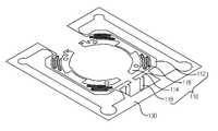
도 2는 본 발명의 판 스프링 구조체(100)를 도시한 평면도이다. 도 3은 본 발명의 지지부(120)가 제거된 판 스프링 구조체(100)를 도시한 사시도이다. 도 4는 본 발명의 보빈(200)이 고정된 판 스프링 구조체(100)를 도시한 사시도이다. 도 2 내지 도 4를 참조하면, 보이스 코일 모터(10)의 판 스프링 구조체(100)는 판 스프링(110), 틀(130) 및 지지부(120)를 포함한다. 판 스프링(110), 틀(130) 및 지지부(120)는 일체로 성형되며, 동일한 평면에 위치한다.2 is a plan view showing the
판 스프링(110)은 렌즈가 장착되는 보빈(200) 및 보빈(200)이 이동 가능하게 삽입되는 하우징(300)을 탄성적으로 연결하여 상기 보빈(200)을 탄성 지지한다. 즉, 보빈(200)의 외주면에 권선된 코일(420)에 전류가 인가되면 인접한 마그네트(430)와의 인력 및 척력에 의하여 보빈(200)을 렌즈의 광축을 따라 이동시키는데, 판 스프링(110)의 일측은 코일(420)이 권선된 보빈(200)과 결합하여 보빈(200)의 이동을 탄성 지지하게 된다.The
한편, 판 스프링(110)은 외부 프레임(112), 내부 프레임(114), 스프링(122) 암(116) 및 단자부(118)를 포함한다. 외부 프레임(112)은 베이스(400)와 결합되고 내부 프레임(114)은 보빈(200)과 결합된다. 따라서, 판 스프링(110)은 보빈(200)과 베이스(400) 사이를 기구적으로 고정, 지지하게 된다.Meanwhile, the
스프링(122) 암(116)은 외부 프레임(112)과 내부 프레임(114) 사이를 탄성적으로 연결하며, 보빈(200)의 이동에 따라 탄성 변형된다. 한편, 도시된 스프링(122) 암(116)은 규칙적인 파문의 개곡선(開曲線) 형상이지만, 그 형상에 의하여 본 발명이 한정되는 것은 아니다.The
단자부(118)는 외부 프레임(112)에 마련되고, 외부 프레임(112)의 외측에 돌출된다. 그리고 보이스 코일 모터(10)의 조립 시 판 스프링(110)의 면에 대하여 수직으로 절곡됨으로써 베이스(400)에 형성된 홈에 삽입된다. 단자부(118)에 전류를 인가함으로써 보이스 코일 모터(10)가 구동된다.The
틀(130)은 판 스프링(110)의 외측에 연결되어 판 스프링(110)의 구조체의 포장 또는 운송 시 판 스프링(110)을 외부의 충격이나 접촉으로부터 판 스프링(110)을 보호하여 준다. 틀(130)과 판 스프링(110)의 외부 프레임(112)이 연결되는 부분은 중심부로 갈수록 넓이가 얇아져 판 스프링(110)의 구조체에서 틀(130)이 용이하게 제거된다.The
지지부(120)는 판 스프링(110)의 내측 및 틀(130)에 연결되며 링(122), 제1연결부(124) 및 제2연결부(126)를 포함한다. 즉, 지지부(120)는 판 스프링(110)의 내부 프레임(114)과 틀(130)에 연결되어 판 스프링(110)의 변형을 방지하여 그 형상을 유지시키며, 보이스 코일 모터(10)의 조립시 보빈(200)을 판 스프링(110)에 고정시키기 전에 지지부(120)는 판 스프링 구조체(100)로부터 제거된다. 링(122)은 내부 프레임(114)의 내측에 마련되고, 링(122)의 외측에 돌출된 제1연결부(124)가 내부 프레임(114)과 링(122)을 연결한다. 제2연결부(126)는 제1연결부(124)와 마찬가지로 링(122)의 외측에 돌출되고, 내부 프레임(114)의 개구된 부분을 통과하여 틀(130)과 링(122)을 연결한다. 도시된 링(122)은 원 형상이지만 사각 링이나 다각형 링 등도 무방하며 그 형상에 의하여 본 발명이 한정되는 것은 아니다.The
한편, 본 발명의 보이스 코일 모터(10)는 렌즈가 장착되는 보빈(200), 보빈(200)이 이동 가능하게 삽입되는 하우징(300) 및 보빈(200) 및 하우징(300)을 탄성적으로 연결하여 보빈(200)을 탄성 지지하는 판 스프링(110)을 포함하며, 판 스 프링(110)은 판 스프링(110)에 틀(130) 및 지지부(120)가 추가 설치된 판 스프링 구조체로(100)부터 지지부(120)가 제거된 후 보빈(200)과 상호 결합되고, 틀(130)이 판 스프링 구조체(100)로부터 분리되어 조립된다.Meanwhile, the
본 발명의 보이스 코일 모터(10)의 조립 방법은, 렌즈가 장착되는 보빈(200) 및 보빈(200)이 이동 가능하게 삽입되는 하우징(300)을 탄성적으로 연결하여 보빈(200)을 탄성 지지하는 판 스프링(110), 판 스프링(110)의 외측에 연결되는 틀(130), 판 스프링(110)의 내측 및 틀(130)에 연결되는 지지부(120)를 포함하는 판 스프링 구조체(100)를 얇은 박막으로부터 프레스 금형으로 분리하는 단계, 판 스프링 구조체(100)에서 상기 지지부(120)를 제거하는 단계, 보빈(200)을 판 스프링(110)에 고정시키는 단계, 판 스프링 구조체(100)에서 틀(130)을 제거하는 단계를 포함한다.In the assembly method of the
이상에서 본 발명에 따른 실시예들이 설명되었으나, 이는 예시적인 것에 불과하며, 당해 분야에서 통상적 지식을 가진 자라면 이로부터 다양한 변형 및 균등한 범위의 실시예가 가능하다는 점을 이해할 것이다. 따라서, 본 발명의 진정한 기술적 보호 범위는 다음의 특허청구범위에 의해서 정해져야 할 것이다.Although embodiments according to the present invention have been described above, these are merely exemplary, and it will be understood by those skilled in the art that various modifications and equivalent embodiments of the present invention are possible therefrom. Accordingly, the true scope of the present invention should be determined by the following claims.
도 1은 본 발명의 일 실시예에 따른 보이스 코일 모터의 분해 사시도이다.1 is an exploded perspective view of a voice coil motor according to an embodiment of the present invention.
도 2는 본 발명의 판 스프링 구조체를 도시한 평면도이다.Figure 2 is a plan view showing a leaf spring structure of the present invention.
도 3은 본 발명의 지지부가 제거된 판 스프링 구조체를 도시한 사시도이다.Figure 3 is a perspective view showing a leaf spring structure with the support of the present invention removed.
도 4는 본 발명의 보빈이 고정된 판 스프링 구조체를 도시한 사시도이다.Figure 4 is a perspective view showing a leaf spring structure fixed to the bobbin of the present invention.
<도면의 주요 부분에 대한 부호의 설명><Explanation of symbols for the main parts of the drawings>
10...보이스 코일 모터100...판 스프링 구조체10 ...
110...판 스프링112...외부 프레임110 ...
114...내부 프레임116...스프링 암114 ...
118...단자부120...지지부118 ...
122...링124...제1연결부122 ...
126...제2연결부130...틀126 ...
200...보빈300...하우징200 ...
400...베이스410...스페이서400 ...
420...코일430...마그네트420
440...커버440 ... cover
Claims (5)
Translated fromKoreanPriority Applications (1)
| Application Number | Priority Date | Filing Date | Title |
|---|---|---|---|
| KR1020090096572AKR101199667B1 (en) | 2009-10-12 | 2009-10-12 | Flat spring of voice coil motor and assembly method of voice coil motor using the same |
Applications Claiming Priority (1)
| Application Number | Priority Date | Filing Date | Title |
|---|---|---|---|
| KR1020090096572AKR101199667B1 (en) | 2009-10-12 | 2009-10-12 | Flat spring of voice coil motor and assembly method of voice coil motor using the same |
Publications (2)
| Publication Number | Publication Date |
|---|---|
| KR20110039637A KR20110039637A (en) | 2011-04-20 |
| KR101199667B1true KR101199667B1 (en) | 2012-11-08 |
Family
ID=44046128
Family Applications (1)
| Application Number | Title | Priority Date | Filing Date |
|---|---|---|---|
| KR1020090096572AActiveKR101199667B1 (en) | 2009-10-12 | 2009-10-12 | Flat spring of voice coil motor and assembly method of voice coil motor using the same |
Country Status (1)
| Country | Link |
|---|---|
| KR (1) | KR101199667B1 (en) |
Cited By (4)
| Publication number | Priority date | Publication date | Assignee | Title |
|---|---|---|---|---|
| CN103997180A (en)* | 2014-06-11 | 2014-08-20 | 深圳市世尊科技有限公司 | Controllable multi-axial-movement spring for voice coil motor |
| KR101515123B1 (en)* | 2013-11-28 | 2015-04-24 | (주)포시스 | A bobbin coupled to the outer side of the spring guide for a cutting device cutting |
| KR101515126B1 (en)* | 2013-11-28 | 2015-04-24 | (주)포시스 | A bobbin coupled to the spring by a cutting device for cutting the inner guide |
| KR101565475B1 (en)* | 2013-11-26 | 2015-11-03 | (주)포시스 | VCM lens and a bobbin of the spring manufacturing method of combining the |
Families Citing this family (18)
| Publication number | Priority date | Publication date | Assignee | Title |
|---|---|---|---|---|
| KR101971639B1 (en)* | 2011-11-30 | 2019-08-13 | 엘지이노텍 주식회사 | Voice coil motor |
| CN102710087B (en)* | 2012-01-09 | 2015-03-18 | 金龙机电股份有限公司 | Reed for voice coil motor, assembly method of reed and produced voice coil motor |
| CN102710088B (en)* | 2012-01-09 | 2015-03-25 | 金龙机电股份有限公司 | Improved voice coil motor |
| CN102967912B (en)* | 2012-01-09 | 2015-07-22 | 金龙机电股份有限公司 | Lens driving device |
| CN203054326U (en)* | 2012-01-09 | 2013-07-10 | 金龙机电股份有限公司 | Lens driving device |
| KR102022090B1 (en)* | 2012-07-30 | 2019-09-18 | 엘지이노텍 주식회사 | Voice coil motor |
| CN103795217B (en)* | 2014-02-17 | 2016-08-17 | 宜兴市贵鑫磁电高科技有限公司 | It is provided with the voice coil motor of pin reinforced structure |
| KR20180064259A (en) | 2016-12-05 | 2018-06-14 | 김규리 | Bath temperature telling the temperature of the water |
| KR102514529B1 (en)* | 2017-05-11 | 2023-03-27 | 주식회사 탑 엔지니어링 | cutting and assembly apparatus for camera module spring |
| KR102262571B1 (en)* | 2019-04-17 | 2021-06-09 | 엘지이노텍 주식회사 | Voice coil motor |
| KR102109774B1 (en)* | 2019-04-17 | 2020-05-12 | 엘지이노텍 주식회사 | Voice coil motor |
| KR102108518B1 (en)* | 2019-09-09 | 2020-05-08 | 엘지이노텍 주식회사 | Voice coil motor |
| KR102270280B1 (en)* | 2020-04-29 | 2021-06-29 | 엘지이노텍 주식회사 | Voice coil motor |
| KR102177843B1 (en)* | 2020-04-29 | 2020-11-11 | 엘지이노텍 주식회사 | Voice coil motor |
| KR102384414B1 (en)* | 2020-05-06 | 2022-04-08 | 엘지이노텍 주식회사 | Voice coil motor |
| KR102415390B1 (en)* | 2020-11-05 | 2022-07-01 | 엘지이노텍 주식회사 | Voice coil motor |
| CN112637455B (en)* | 2020-12-08 | 2022-07-08 | Oppo广东移动通信有限公司 | Camera motor, camera and electronic device |
| CN113389832B (en)* | 2021-07-16 | 2025-01-07 | 成都易迅光电科技有限公司 | A new type of stacked filled spring |
Citations (3)
| Publication number | Priority date | Publication date | Assignee | Title |
|---|---|---|---|---|
| KR100562720B1 (en) | 2004-05-19 | 2006-03-20 | 주식회사 포엠 | Compact camera device for communication device and communication device having same |
| KR100614763B1 (en) | 2004-08-11 | 2006-08-23 | 주식회사 하이소닉 | Video recording device |
| JP2008310237A (en)* | 2007-06-18 | 2008-12-25 | Shicoh Engineering Co Ltd | Lens-driving device, camera and mobile phone with camera |
- 2009
- 2009-10-12KRKR1020090096572Apatent/KR101199667B1/enactiveActive
Patent Citations (3)
| Publication number | Priority date | Publication date | Assignee | Title |
|---|---|---|---|---|
| KR100562720B1 (en) | 2004-05-19 | 2006-03-20 | 주식회사 포엠 | Compact camera device for communication device and communication device having same |
| KR100614763B1 (en) | 2004-08-11 | 2006-08-23 | 주식회사 하이소닉 | Video recording device |
| JP2008310237A (en)* | 2007-06-18 | 2008-12-25 | Shicoh Engineering Co Ltd | Lens-driving device, camera and mobile phone with camera |
Cited By (5)
| Publication number | Priority date | Publication date | Assignee | Title |
|---|---|---|---|---|
| KR101565475B1 (en)* | 2013-11-26 | 2015-11-03 | (주)포시스 | VCM lens and a bobbin of the spring manufacturing method of combining the |
| KR101515123B1 (en)* | 2013-11-28 | 2015-04-24 | (주)포시스 | A bobbin coupled to the outer side of the spring guide for a cutting device cutting |
| KR101515126B1 (en)* | 2013-11-28 | 2015-04-24 | (주)포시스 | A bobbin coupled to the spring by a cutting device for cutting the inner guide |
| CN103997180A (en)* | 2014-06-11 | 2014-08-20 | 深圳市世尊科技有限公司 | Controllable multi-axial-movement spring for voice coil motor |
| CN103997180B (en)* | 2014-06-11 | 2016-08-10 | 深圳市世尊科技有限公司 | Controllable Multi-Axis Motion Springs for Voice Coil Motors |
Also Published As
| Publication number | Publication date |
|---|---|
| KR20110039637A (en) | 2011-04-20 |
Similar Documents
| Publication | Publication Date | Title |
|---|---|---|
| KR101199667B1 (en) | Flat spring of voice coil motor and assembly method of voice coil motor using the same | |
| KR101072677B1 (en) | Voice coil motor and assembly method of the same | |
| KR101081631B1 (en) | Voice coil motor | |
| US7751134B2 (en) | Lens actuator, and electronic device using the same | |
| KR101230089B1 (en) | Voice coil motor | |
| US7990625B2 (en) | Camera module | |
| KR101230199B1 (en) | Voice coil motor | |
| KR101230128B1 (en) | Voice coil motor | |
| CN102073194B (en) | Camera module with autofocus function | |
| US10205371B2 (en) | Voice coil motor | |
| KR101644191B1 (en) | Voice coil motor and assembly method of the same | |
| KR101009129B1 (en) | Camera module | |
| US8643964B2 (en) | Lens driving device without permanent magnet | |
| KR20120090382A (en) | Voice coil motor | |
| KR20080099567A (en) | Small camera | |
| KR20120025811A (en) | Voice coil motor | |
| KR20110029346A (en) | Voice coil motor and its assembly method | |
| KR101696927B1 (en) | Voice coil motor | |
| KR20110076063A (en) | Voice coil motor | |
| JP2009036825A (en) | Lens drive device | |
| JP2008090008A (en) | Lens driving apparatus | |
| KR20110029345A (en) | Voice coil motor and its manufacturing method | |
| WO2016199394A1 (en) | Lens driving device, camera module, and camera-equipped apparatus | |
| JP2006017924A (en) | Small camera | |
| US20130154396A1 (en) | Voice coil motor |
Legal Events
| Date | Code | Title | Description |
|---|---|---|---|
| PA0109 | Patent application | Patent event code:PA01091R01D Comment text:Patent Application Patent event date:20091012 | |
| A201 | Request for examination | ||
| PA0201 | Request for examination | Patent event code:PA02012R01D Patent event date:20110401 Comment text:Request for Examination of Application Patent event code:PA02011R01I Patent event date:20091012 Comment text:Patent Application | |
| PG1501 | Laying open of application | ||
| PE0902 | Notice of grounds for rejection | Comment text:Notification of reason for refusal Patent event date:20120502 Patent event code:PE09021S01D | |
| E701 | Decision to grant or registration of patent right | ||
| PE0701 | Decision of registration | Patent event code:PE07011S01D Comment text:Decision to Grant Registration Patent event date:20121025 | |
| GRNT | Written decision to grant | ||
| PR0701 | Registration of establishment | Comment text:Registration of Establishment Patent event date:20121102 Patent event code:PR07011E01D | |
| PR1002 | Payment of registration fee | Payment date:20121102 End annual number:3 Start annual number:1 | |
| PG1601 | Publication of registration | ||
| FPAY | Annual fee payment | Payment date:20151005 Year of fee payment:4 | |
| PR1001 | Payment of annual fee | Payment date:20151005 Start annual number:4 End annual number:4 | |
| FPAY | Annual fee payment | Payment date:20161006 Year of fee payment:5 | |
| PR1001 | Payment of annual fee | Payment date:20161006 Start annual number:5 End annual number:5 | |
| FPAY | Annual fee payment | Payment date:20171011 Year of fee payment:6 | |
| PR1001 | Payment of annual fee | Payment date:20171011 Start annual number:6 End annual number:6 | |
| FPAY | Annual fee payment | Payment date:20181010 Year of fee payment:7 | |
| PR1001 | Payment of annual fee | Payment date:20181010 Start annual number:7 End annual number:7 | |
| FPAY | Annual fee payment | Payment date:20191010 Year of fee payment:8 | |
| PR1001 | Payment of annual fee | Payment date:20191010 Start annual number:8 End annual number:8 | |
| PR1001 | Payment of annual fee | Payment date:20201013 Start annual number:9 End annual number:9 | |
| PR1001 | Payment of annual fee | Payment date:20211013 Start annual number:10 End annual number:10 | |
| PR1001 | Payment of annual fee | Payment date:20221011 Start annual number:11 End annual number:11 | |
| PR1001 | Payment of annual fee | Payment date:20231012 Start annual number:12 End annual number:12 | |
| PR1001 | Payment of annual fee | Payment date:20241015 Start annual number:13 End annual number:13 |