KR101197655B1 - Intervertebral disc prosthesis - Google Patents
Intervertebral disc prosthesisDownload PDFInfo
- Publication number
- KR101197655B1 KR101197655B1KR1020067022408AKR20067022408AKR101197655B1KR 101197655 B1KR101197655 B1KR 101197655B1KR 1020067022408 AKR1020067022408 AKR 1020067022408AKR 20067022408 AKR20067022408 AKR 20067022408AKR 101197655 B1KR101197655 B1KR 101197655B1
- Authority
- KR
- South Korea
- Prior art keywords
- core
- plate
- prosthesis
- intervertebral disc
- coupling means
- Prior art date
- Legal status (The legal status is an assumption and is not a legal conclusion. Google has not performed a legal analysis and makes no representation as to the accuracy of the status listed.)
- Expired - Fee Related
Links
Images


Classifications
- A—HUMAN NECESSITIES
- A61—MEDICAL OR VETERINARY SCIENCE; HYGIENE
- A61F—FILTERS IMPLANTABLE INTO BLOOD VESSELS; PROSTHESES; DEVICES PROVIDING PATENCY TO, OR PREVENTING COLLAPSING OF, TUBULAR STRUCTURES OF THE BODY, e.g. STENTS; ORTHOPAEDIC, NURSING OR CONTRACEPTIVE DEVICES; FOMENTATION; TREATMENT OR PROTECTION OF EYES OR EARS; BANDAGES, DRESSINGS OR ABSORBENT PADS; FIRST-AID KITS
- A61F2/00—Filters implantable into blood vessels; Prostheses, i.e. artificial substitutes or replacements for parts of the body; Appliances for connecting them with the body; Devices providing patency to, or preventing collapsing of, tubular structures of the body, e.g. stents
- A61F2/02—Prostheses implantable into the body
- A61F2/30—Joints
- A61F2/44—Joints for the spine, e.g. vertebrae, spinal discs
- A61F2/442—Intervertebral or spinal discs, e.g. resilient
- A61F2/4425—Intervertebral or spinal discs, e.g. resilient made of articulated components
- A—HUMAN NECESSITIES
- A61—MEDICAL OR VETERINARY SCIENCE; HYGIENE
- A61F—FILTERS IMPLANTABLE INTO BLOOD VESSELS; PROSTHESES; DEVICES PROVIDING PATENCY TO, OR PREVENTING COLLAPSING OF, TUBULAR STRUCTURES OF THE BODY, e.g. STENTS; ORTHOPAEDIC, NURSING OR CONTRACEPTIVE DEVICES; FOMENTATION; TREATMENT OR PROTECTION OF EYES OR EARS; BANDAGES, DRESSINGS OR ABSORBENT PADS; FIRST-AID KITS
- A61F2/00—Filters implantable into blood vessels; Prostheses, i.e. artificial substitutes or replacements for parts of the body; Appliances for connecting them with the body; Devices providing patency to, or preventing collapsing of, tubular structures of the body, e.g. stents
- A61F2/02—Prostheses implantable into the body
- A61F2/30—Joints
- A61F2/44—Joints for the spine, e.g. vertebrae, spinal discs
- A61F2/442—Intervertebral or spinal discs, e.g. resilient
- A—HUMAN NECESSITIES
- A61—MEDICAL OR VETERINARY SCIENCE; HYGIENE
- A61F—FILTERS IMPLANTABLE INTO BLOOD VESSELS; PROSTHESES; DEVICES PROVIDING PATENCY TO, OR PREVENTING COLLAPSING OF, TUBULAR STRUCTURES OF THE BODY, e.g. STENTS; ORTHOPAEDIC, NURSING OR CONTRACEPTIVE DEVICES; FOMENTATION; TREATMENT OR PROTECTION OF EYES OR EARS; BANDAGES, DRESSINGS OR ABSORBENT PADS; FIRST-AID KITS
- A61F2/00—Filters implantable into blood vessels; Prostheses, i.e. artificial substitutes or replacements for parts of the body; Appliances for connecting them with the body; Devices providing patency to, or preventing collapsing of, tubular structures of the body, e.g. stents
- A61F2/02—Prostheses implantable into the body
- A61F2/30—Joints
- A61F2002/30001—Additional features of subject-matter classified in A61F2/28, A61F2/30 and subgroups thereof
- A61F2002/30316—The prosthesis having different structural features at different locations within the same prosthesis; Connections between prosthetic parts; Special structural features of bone or joint prostheses not otherwise provided for
- A61F2002/30329—Connections or couplings between prosthetic parts, e.g. between modular parts; Connecting elements
- A61F2002/30331—Connections or couplings between prosthetic parts, e.g. between modular parts; Connecting elements made by longitudinally pushing a protrusion into a complementarily-shaped recess, e.g. held by friction fit
- A61F2002/30362—Connections or couplings between prosthetic parts, e.g. between modular parts; Connecting elements made by longitudinally pushing a protrusion into a complementarily-shaped recess, e.g. held by friction fit with possibility of relative movement between the protrusion and the recess
- A—HUMAN NECESSITIES
- A61—MEDICAL OR VETERINARY SCIENCE; HYGIENE
- A61F—FILTERS IMPLANTABLE INTO BLOOD VESSELS; PROSTHESES; DEVICES PROVIDING PATENCY TO, OR PREVENTING COLLAPSING OF, TUBULAR STRUCTURES OF THE BODY, e.g. STENTS; ORTHOPAEDIC, NURSING OR CONTRACEPTIVE DEVICES; FOMENTATION; TREATMENT OR PROTECTION OF EYES OR EARS; BANDAGES, DRESSINGS OR ABSORBENT PADS; FIRST-AID KITS
- A61F2/00—Filters implantable into blood vessels; Prostheses, i.e. artificial substitutes or replacements for parts of the body; Appliances for connecting them with the body; Devices providing patency to, or preventing collapsing of, tubular structures of the body, e.g. stents
- A61F2/02—Prostheses implantable into the body
- A61F2/30—Joints
- A61F2002/30001—Additional features of subject-matter classified in A61F2/28, A61F2/30 and subgroups thereof
- A61F2002/30316—The prosthesis having different structural features at different locations within the same prosthesis; Connections between prosthetic parts; Special structural features of bone or joint prostheses not otherwise provided for
- A61F2002/30329—Connections or couplings between prosthetic parts, e.g. between modular parts; Connecting elements
- A61F2002/30383—Connections or couplings between prosthetic parts, e.g. between modular parts; Connecting elements made by laterally inserting a protrusion, e.g. a rib into a complementarily-shaped groove
- A61F2002/3039—Connections or couplings between prosthetic parts, e.g. between modular parts; Connecting elements made by laterally inserting a protrusion, e.g. a rib into a complementarily-shaped groove with possibility of relative movement of the rib within the groove
- A—HUMAN NECESSITIES
- A61—MEDICAL OR VETERINARY SCIENCE; HYGIENE
- A61F—FILTERS IMPLANTABLE INTO BLOOD VESSELS; PROSTHESES; DEVICES PROVIDING PATENCY TO, OR PREVENTING COLLAPSING OF, TUBULAR STRUCTURES OF THE BODY, e.g. STENTS; ORTHOPAEDIC, NURSING OR CONTRACEPTIVE DEVICES; FOMENTATION; TREATMENT OR PROTECTION OF EYES OR EARS; BANDAGES, DRESSINGS OR ABSORBENT PADS; FIRST-AID KITS
- A61F2/00—Filters implantable into blood vessels; Prostheses, i.e. artificial substitutes or replacements for parts of the body; Appliances for connecting them with the body; Devices providing patency to, or preventing collapsing of, tubular structures of the body, e.g. stents
- A61F2/02—Prostheses implantable into the body
- A61F2/30—Joints
- A61F2002/30001—Additional features of subject-matter classified in A61F2/28, A61F2/30 and subgroups thereof
- A61F2002/30316—The prosthesis having different structural features at different locations within the same prosthesis; Connections between prosthetic parts; Special structural features of bone or joint prostheses not otherwise provided for
- A61F2002/30329—Connections or couplings between prosthetic parts, e.g. between modular parts; Connecting elements
- A61F2002/30518—Connections or couplings between prosthetic parts, e.g. between modular parts; Connecting elements with possibility of relative movement between the prosthetic parts
- A61F2002/30528—Means for limiting said movement
- A—HUMAN NECESSITIES
- A61—MEDICAL OR VETERINARY SCIENCE; HYGIENE
- A61F—FILTERS IMPLANTABLE INTO BLOOD VESSELS; PROSTHESES; DEVICES PROVIDING PATENCY TO, OR PREVENTING COLLAPSING OF, TUBULAR STRUCTURES OF THE BODY, e.g. STENTS; ORTHOPAEDIC, NURSING OR CONTRACEPTIVE DEVICES; FOMENTATION; TREATMENT OR PROTECTION OF EYES OR EARS; BANDAGES, DRESSINGS OR ABSORBENT PADS; FIRST-AID KITS
- A61F2/00—Filters implantable into blood vessels; Prostheses, i.e. artificial substitutes or replacements for parts of the body; Appliances for connecting them with the body; Devices providing patency to, or preventing collapsing of, tubular structures of the body, e.g. stents
- A61F2/02—Prostheses implantable into the body
- A61F2/30—Joints
- A61F2002/30001—Additional features of subject-matter classified in A61F2/28, A61F2/30 and subgroups thereof
- A61F2002/30316—The prosthesis having different structural features at different locations within the same prosthesis; Connections between prosthetic parts; Special structural features of bone or joint prostheses not otherwise provided for
- A61F2002/30535—Special structural features of bone or joint prostheses not otherwise provided for
- A61F2002/30563—Special structural features of bone or joint prostheses not otherwise provided for having elastic means or damping means, different from springs, e.g. including an elastomeric core or shock absorbers
- A—HUMAN NECESSITIES
- A61—MEDICAL OR VETERINARY SCIENCE; HYGIENE
- A61F—FILTERS IMPLANTABLE INTO BLOOD VESSELS; PROSTHESES; DEVICES PROVIDING PATENCY TO, OR PREVENTING COLLAPSING OF, TUBULAR STRUCTURES OF THE BODY, e.g. STENTS; ORTHOPAEDIC, NURSING OR CONTRACEPTIVE DEVICES; FOMENTATION; TREATMENT OR PROTECTION OF EYES OR EARS; BANDAGES, DRESSINGS OR ABSORBENT PADS; FIRST-AID KITS
- A61F2/00—Filters implantable into blood vessels; Prostheses, i.e. artificial substitutes or replacements for parts of the body; Appliances for connecting them with the body; Devices providing patency to, or preventing collapsing of, tubular structures of the body, e.g. stents
- A61F2/02—Prostheses implantable into the body
- A61F2/30—Joints
- A61F2002/30001—Additional features of subject-matter classified in A61F2/28, A61F2/30 and subgroups thereof
- A61F2002/30316—The prosthesis having different structural features at different locations within the same prosthesis; Connections between prosthetic parts; Special structural features of bone or joint prostheses not otherwise provided for
- A61F2002/30535—Special structural features of bone or joint prostheses not otherwise provided for
- A61F2002/30604—Special structural features of bone or joint prostheses not otherwise provided for modular
- A61F2002/30616—Sets comprising a plurality of prosthetic parts of different sizes or orientations
- A—HUMAN NECESSITIES
- A61—MEDICAL OR VETERINARY SCIENCE; HYGIENE
- A61F—FILTERS IMPLANTABLE INTO BLOOD VESSELS; PROSTHESES; DEVICES PROVIDING PATENCY TO, OR PREVENTING COLLAPSING OF, TUBULAR STRUCTURES OF THE BODY, e.g. STENTS; ORTHOPAEDIC, NURSING OR CONTRACEPTIVE DEVICES; FOMENTATION; TREATMENT OR PROTECTION OF EYES OR EARS; BANDAGES, DRESSINGS OR ABSORBENT PADS; FIRST-AID KITS
- A61F2/00—Filters implantable into blood vessels; Prostheses, i.e. artificial substitutes or replacements for parts of the body; Appliances for connecting them with the body; Devices providing patency to, or preventing collapsing of, tubular structures of the body, e.g. stents
- A61F2/02—Prostheses implantable into the body
- A61F2/30—Joints
- A61F2002/30001—Additional features of subject-matter classified in A61F2/28, A61F2/30 and subgroups thereof
- A61F2002/30621—Features concerning the anatomical functioning or articulation of the prosthetic joint
- A61F2002/30649—Ball-and-socket joints
- A61F2002/3065—Details of the ball-shaped head
- A—HUMAN NECESSITIES
- A61—MEDICAL OR VETERINARY SCIENCE; HYGIENE
- A61F—FILTERS IMPLANTABLE INTO BLOOD VESSELS; PROSTHESES; DEVICES PROVIDING PATENCY TO, OR PREVENTING COLLAPSING OF, TUBULAR STRUCTURES OF THE BODY, e.g. STENTS; ORTHOPAEDIC, NURSING OR CONTRACEPTIVE DEVICES; FOMENTATION; TREATMENT OR PROTECTION OF EYES OR EARS; BANDAGES, DRESSINGS OR ABSORBENT PADS; FIRST-AID KITS
- A61F2/00—Filters implantable into blood vessels; Prostheses, i.e. artificial substitutes or replacements for parts of the body; Appliances for connecting them with the body; Devices providing patency to, or preventing collapsing of, tubular structures of the body, e.g. stents
- A61F2/02—Prostheses implantable into the body
- A61F2/30—Joints
- A61F2002/30001—Additional features of subject-matter classified in A61F2/28, A61F2/30 and subgroups thereof
- A61F2002/30621—Features concerning the anatomical functioning or articulation of the prosthetic joint
- A61F2002/30649—Ball-and-socket joints
- A61F2002/30654—Details of the concave socket
- A—HUMAN NECESSITIES
- A61—MEDICAL OR VETERINARY SCIENCE; HYGIENE
- A61F—FILTERS IMPLANTABLE INTO BLOOD VESSELS; PROSTHESES; DEVICES PROVIDING PATENCY TO, OR PREVENTING COLLAPSING OF, TUBULAR STRUCTURES OF THE BODY, e.g. STENTS; ORTHOPAEDIC, NURSING OR CONTRACEPTIVE DEVICES; FOMENTATION; TREATMENT OR PROTECTION OF EYES OR EARS; BANDAGES, DRESSINGS OR ABSORBENT PADS; FIRST-AID KITS
- A61F2/00—Filters implantable into blood vessels; Prostheses, i.e. artificial substitutes or replacements for parts of the body; Appliances for connecting them with the body; Devices providing patency to, or preventing collapsing of, tubular structures of the body, e.g. stents
- A61F2/02—Prostheses implantable into the body
- A61F2/30—Joints
- A61F2/44—Joints for the spine, e.g. vertebrae, spinal discs
- A61F2/442—Intervertebral or spinal discs, e.g. resilient
- A61F2/4425—Intervertebral or spinal discs, e.g. resilient made of articulated components
- A61F2002/443—Intervertebral or spinal discs, e.g. resilient made of articulated components having two transversal endplates and at least one intermediate component
- A—HUMAN NECESSITIES
- A61—MEDICAL OR VETERINARY SCIENCE; HYGIENE
- A61F—FILTERS IMPLANTABLE INTO BLOOD VESSELS; PROSTHESES; DEVICES PROVIDING PATENCY TO, OR PREVENTING COLLAPSING OF, TUBULAR STRUCTURES OF THE BODY, e.g. STENTS; ORTHOPAEDIC, NURSING OR CONTRACEPTIVE DEVICES; FOMENTATION; TREATMENT OR PROTECTION OF EYES OR EARS; BANDAGES, DRESSINGS OR ABSORBENT PADS; FIRST-AID KITS
- A61F2220/00—Fixations or connections for prostheses classified in groups A61F2/00 - A61F2/26 or A61F2/82 or A61F9/00 or A61F11/00 or subgroups thereof
- A61F2220/0025—Connections or couplings between prosthetic parts, e.g. between modular parts; Connecting elements
- A61F2220/0033—Connections or couplings between prosthetic parts, e.g. between modular parts; Connecting elements made by longitudinally pushing a protrusion into a complementary-shaped recess, e.g. held by friction fit
Landscapes
- Health & Medical Sciences (AREA)
- Engineering & Computer Science (AREA)
- Biomedical Technology (AREA)
- Orthopedic Medicine & Surgery (AREA)
- Neurology (AREA)
- Heart & Thoracic Surgery (AREA)
- Oral & Maxillofacial Surgery (AREA)
- Transplantation (AREA)
- Cardiology (AREA)
- Vascular Medicine (AREA)
- Life Sciences & Earth Sciences (AREA)
- Animal Behavior & Ethology (AREA)
- General Health & Medical Sciences (AREA)
- Public Health (AREA)
- Veterinary Medicine (AREA)
- Prostheses (AREA)
Abstract
Translated fromKoreanDescription
Translated fromKorean본 발명은 섬유성 연골 디스크(fibro-cartilaginous disc)의 대용으로 사용하여 척추(the spinal column)의 척추골(vertebrae) 간의 결합을 확실히 하는 것을 목적으로 하는 추간판 보철물에 관한 것이다.The present invention relates to an intervertebral disc prosthesis aimed at ensuring the coupling between the vertebrae of the spinal column using a fibro-cartilaginous disc.
종래기술로서 여러 가지 타입의 추간판 보철물이 알려져 있다. 예를 들어, 프랑스 특허출원 제2 846 550호 및 국제특허출원 WO 02 089 701호에 개시된 다수의 보철물들은, 중심 코어(central core) 둘레에 일종의 케이지(cage)를 형성하는 하측 플레이트(lower plate)와 상측 플레이트(upper plate)로 구성되어 있다. 이러한 보철물들의 일부분은 상측 플레이트가 중심 코어에 대하여 선회(swivel) 할 수 있도록 하고, 선택적으로 중심 코어를 하측 플레이트에 대해 슬라이드시킬 수 있도록 한다. 중심 코어의 하측 플레이트에 대한 슬라이딩은 필수적인 특징인데, 이것은 보철물을 착용하고 있는 환자가 움직이는 동안, 보철물에 부과되는 압박을 흡수하는 이상적인 위치에 코어가 자발적으로 위치하도록 해야 하기 때문이다. 불균일한 표면 주위로의 적어도 하나의 플레이트와 상호작용하는 코어의 변위에 의해, 보철물의 플레이트들 간의 경사를 가능하게 하여, 보철물을 착용한 환자의 움직임을 용이하게 한다. 코어의 변위는, 또한, 큰 압박을 받을 때 크리프(creep)의 발생을 방지한다.Various types of intervertebral disc prostheses are known as prior art. For example, many of the prostheses disclosed in French Patent Application No. 2 846 550 and International Patent Application WO 02 089 701 form a lower plate that forms a kind of cage around a central core. And upper plate. Some of these prostheses allow the upper plate to swivel with respect to the center core and optionally allow the center core to slide against the lower plate. Sliding to the lower plate of the central core is an essential feature, since the core should be spontaneously positioned in an ideal position to absorb the pressure imposed on the prosthesis while the patient wearing the prosthesis moves. Displacement of the core interacting with the at least one plate around the non-uniform surface enables tilt between the plates of the prosthesis, thereby facilitating the movement of the patient wearing the prosthesis. The displacement of the core also prevents the occurrence of creep when under high pressure.
이러한 상황에서, 플레이트들 사이에 영구적인 경사가 지도록 하고, 예를 들어, 척추전만(lordosis)을 유도하는 보철물을 제공하는 것이 중요하다. 보철물을 착용하는 환자의 척추의 장해에 따라, 때때로 보철물이 이러한 장해를 보정하는 것이 바람직하다. 외과의(surgeon)의 요망에 따라, 코어의 변위는 적어도 한 방향으로 제한되어야 한다. 그러나, 환자가 움직일 때, 보철물의 구성요소의 상대적인 위치는, 변위의 허용된 범위 내에서 변경될 수 있다.In such a situation, it is important to provide a prosthesis that allows a permanent slope between the plates and, for example, induces lordosis. Depending on the disorder of the spine of the patient wearing the prosthesis, it is sometimes desirable for the prosthesis to correct this disorder. According to the surgeon's desire, the displacement of the core should be limited in at least one direction. However, when the patient moves, the relative position of the components of the prosthesis may change within the allowed range of displacement.
본 발명의 어떤 실시예의 하나의 목적은, 보철물의 다양한 부품들 상호 간의 한정된 움직임(이동)을 가능하게 하고, 적어도 하나의 방향으로 그의 변위를 제한하도록 사용되는 코어를 포함하는, 추간판 보철물을 제공하는 것이다.One object of certain embodiments of the present invention is to provide an intervertebral disc prosthesis comprising a core used to allow limited movement (movement) between various parts of the prosthesis and to limit its displacement in at least one direction. will be.
제1플레이트, 제2플레이트 및 적어도 회전하는, 적어도 플레이트 중 하나에 대하여, 움직이는 코어를 포함하는 세부분으로 구성되는 추간판 보철물로서, 코어는 제1플레이트의 상보적인 곡면의 적어도 일부분과 접촉하는 곡면과, 제2플레이트의 실질적으로 평평한 면의 적어도 일부와 접촉하는 실질적으로 평평한 면을 가지고, 제2플레이트와 코어의 주변(periphery) 가까이에 위치하는 수 및 암 결합수단은 실질적으로 평평한 면과 실질적으로 평행하는 축을 따라 제2플레이트에 대하여 코어의 이동에서 움직임을 제한하거나 막도록 하고, 실질적으로 평평한 면에 실질적으로 수직인 축 주위로, 제2플레이트에 대해 코어의 회전에서 움직임을 제한하거나 막도록 하며, 코어의 곡면의 정상부는 코어의 이 곡면의 기하학적인 중심과의 관계에서 적어도 한 방향으로 중심에서 벗어나 있다.An intervertebral plate prosthesis consisting of details comprising a moving core, with respect to at least one of a first plate, a second plate and at least a plate, the core having a curved surface in contact with at least a portion of the complementary curved surface of the first plate. The male and female coupling means having a substantially flat surface in contact with at least a portion of the substantially flat surface of the second plate and located near the periphery of the second plate and the core are substantially parallel to the substantially flat surface. Limiting or preventing movement in the movement of the core with respect to the second plate along an axis thereof, around the axis substantially perpendicular to the substantially flat surface, limiting or preventing movement in the rotation of the core relative to the second plate, The top of the surface of the core is at least one square in relation to the geometric center of this surface of the core. As it has off-center.
다른 실시예에 따르면, 환자가 움직이지 않을때, 코어의 나머지 부분은, 제1 및 제2 플레이트의 대칭축이 척추골에 고정되어 있고, 코어의 곡면과 상보적인 제1플레이트의 곡면이 플레이트의 대칭축과 함께 코어의 이 곡면의 중심에서 벗어난 정상부를 정렬하도록 유도하는 사실 때문에, 코어의 곡면의 정상부의 벗어난 중심의 방향과 반대방향으로 이동되며, 따라서 그 곡면의 중심에서 벗어난 정상부의 방향과 반대방향으로의 코어의 이동(shifting)은 코어에 존재하는 결합수단과 제2플레이트에 존재하는 결합수단의 접합을 야기하고, 이러한 접합은 결과적으로 곡면의 중심에서 벗어난 정상부의 방향과 반대방향으로 코어의 변위(displacement)를 제한한다.According to another embodiment, when the patient is not moving, the remainder of the core has the axis of symmetry of the first and second plates fixed to the vertebrae and the surface of the first plate complementary to the surface of the core has an axis of symmetry of the plate. Due to the fact that they together lead to align the tops off the center of this curved surface of the core, they are moved in a direction opposite to the direction of the off center of the top of the curved surface of the core, and therefore in the opposite direction of the tops off the center of the curved surface. The shifting of the core results in the joining of the joining means present in the core and the joining means present in the second plate, and this joining results in displacement of the core in the direction opposite to the direction of the top off the center of the curved surface. ).
다른 실시예에 따르면, 동일한 플레이트가 다른 코어들과 조립되고, 코어들간의 차는 코어의 이 곡면의 중심에 대하여 그들의 곡면의 중심의 위치를 포함한다.According to another embodiment, the same plate is assembled with other cores, and the difference between the cores includes the position of the center of their curved surface with respect to the center of this curved surface of the core.
다른 실시예에 따르면, 동일한 코어들이 다른 플레이트들과 조립되고, 플레이트들 간의 차는 플레이트들의 상측 면 및 하측 면을 나타내는 중간 평면 사이의 각도를 포함한다.According to another embodiment, the same cores are assembled with other plates and the difference between the plates comprises an angle between the intermediate plane representing the upper and lower sides of the plates.
다른 실시예에 따르면, 상측 플레이트의 상측 면과 제2플레이트의 하측 면 사이의 각도는, 제2플레이트 및/또는 제1플레이트의 상측 면 및 하측 면을 나타내는 중간 평면이 각을 만들어내는 사실 또는, 결합수단에 의해, 플레이트 중 적어도 어느 하나의 기울기를 부과하는 위치에 대하여 코어의 움직임을 제한함으로써, 부과된다.According to another embodiment, the angle between the upper face of the upper plate and the lower face of the second plate is such that the intermediate plane representing the upper face and the lower face of the second plate and / or the first plate creates an angle, or By means of engaging means is imposed by limiting the movement of the core relative to the position which imposes the inclination of at least one of the plates.
다른 실시예에 따르면, 동일한 플레이트들이 다른 두께 및/또는 크기의 코어들과 조립된다.According to another embodiment, the same plates are assembled with cores of different thickness and / or size.
다른 실시예에 따르면, 코어의 곡면은 코어의 볼록한 상측 면이고, 제1플레이트의 곡면은 상측 플레이트의 하측 면의 불록부이다.According to another embodiment, the curved surface of the core is a convex upper surface of the core and the curved surface of the first plate is a block on the lower surface of the upper plate.
다른 실시예에 따르면, 각각의 수 결합수단의 크기는 각각의 암 결합수단의 크기보다 약간 작아서, 코어와 제2플레이트 사이에 간극을 형성하게 한다.According to another embodiment, the size of each male coupling means is slightly smaller than the size of each female coupling means, thereby forming a gap between the core and the second plate.
다른 실시예에 따르면, 각각의 수 결합 수단의 치수는 각각의 암 결합 수단의 크기와 실질적으로 동일하여 코어와 제2플레이트 사이의 어떤 간극도 없도록 한다.According to another embodiment, the dimensions of each male coupling means are substantially the same as the size of each female coupling means such that there is no gap between the core and the second plate.
다른 실시예에 따르면, 코어는 폴리에틸렌으로 제작된다.According to another embodiment, the core is made of polyethylene.
다른 실시예에 따르면, 제1 및 제2플레이트는 금속으로 제작된다.According to another embodiment, the first and second plates are made of metal.
다른 실시예에 따르면, 제2플레이트는 코어의 수 결합 수단과 결합되는 암 결합 수단을 포함한다.According to another embodiment, the second plate comprises female coupling means engaged with the male coupling means of the core.
다른 실시예에 따르면, 코어의 수 결합 수단은 코어의 두개의 측면 에지에 위치하는 두개의 접촉 플레이트이고, 제2플레이트의 암 결합 수단은 제2플레이트의 두개의 측면 에지의 각각에 쌍으로 위치하는 네개의 벽이다.According to another embodiment, the male coupling means of the core is two contact plates located at two side edges of the core, and the female coupling means of the second plate are located in pairs at each of the two side edges of the second plate. Four walls.
다른 실시예에 따르면, 제2플레이트의 암 결합수단을 형성하는 벽들은 보철물의 중심을 향하여 구부러져서, 코어의 수 결합 수단의 적어도 일부를 감싸고, 코어의 수 결합 수단이 들려지는 것을 방지한다.According to another embodiment, the walls forming the female engagement means of the second plate are bent towards the center of the prosthesis to enclose at least part of the male engagement means of the core and to prevent the male engagement means of the core from being lifted.
다른 실시예에 따르면, 제2플레이트는 코어의 암 결합 수단과 결합하는 수 결합 수단을 포함한다.According to another embodiment, the second plate comprises male coupling means for engaging with the female coupling means of the core.
다른 실시예에 따르면, 제2플레이트의 수 결합 수단은 보철물의 두 에지에서 서로서로 마주보는 두 개의 접촉 플레이트이고, 코어의 암 결합 수단은 두개의 오목부이다.According to another embodiment, the male engagement means of the second plate are two contact plates facing each other at two edges of the prosthesis, and the female engagement means of the core are two recesses.
다른 실시예에 따르면, 제2플레이트의 수 결합 수단은 보철물의 두개의 에지의 근처에서 서로 마주보며, 코어의 암 결합 수단은 오목부이다.According to another embodiment, the male engagement means of the second plate face each other near the two edges of the prosthesis, and the female engagement means of the core is a recess.
다른 실시예에 따르면, 제2플레이트의 수 결합 수단은 보철물의 내부를 향해 구부러지고 보철물의 두개의 에지에서 서로 마주보는 두개의 첨두(nib)이고, 코어의 암 결합 수단은 두 개의 오목부이다.According to another embodiment, the male engagement means of the second plate are two nibs that are bent towards the interior of the prosthesis and face each other at two edges of the prosthesis, and the female engagement means of the core are two recesses.
삭제delete
다른 실시예에 따르면, 제1플레이트는 척추골의 형태에 적합한 그 상측 면의 적어도 일부분에서 볼록하게 되어 있다.According to another embodiment, the first plate is convex on at least a portion of its upper face suitable for the shape of the vertebrae.
다양한 실시예의 다른 특징 및 장점은 첨부된 도면을 참조로 하여, 이하의 설명에서 소개되며, 첨부된 도면은 다음과 같다:Other features and advantages of various embodiments are introduced in the following description with reference to the accompanying drawings, which are as follows:
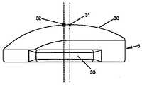
도 1a 및 도 1b는 각각 본 발명의 일실시예에 따른 보철물의 중심의 측면도와 평면도를 나타내고,1A and 1B show a side view and a plan view, respectively, of a center of a prosthesis according to an embodiment of the present invention;
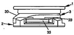
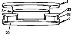
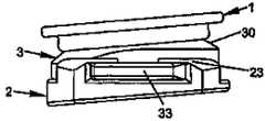
도 2a 및 도 2b는 각각 본 발명의 제1실시예에서의 보철물의 전면도와 측면도를 나타내고, 도 2c 및 도 2d는 각각 본 발명의 제2실시예의 보철물의 투시도 및 측면도를 나타내며,2A and 2B show front and side views, respectively, of the prosthesis in the first embodiment of the present invention, and FIGS. 2C and 2D respectively show perspective and side views of the prosthesis of the second embodiment of the present invention,
도 3a 및 도 3b는 각각 본 발명의 일실시예에서 보철물의 하측 플레이트의 평면도와 도 3a의 A-A에 따른 단면도를 나타내고, 도 3c는 코어가 있는 하측 플레이트의 평면도를 나타내며, 도 3d와 도 3e는 각각 본 발명의 일실시예에서 보철물의 상측 플레이트의 평면도와 도 3d의 B-B에 따른 단면도를 나타낸다.3A and 3B respectively show a plan view of the lower plate of the prosthesis and a cross-sectional view along AA of FIG. 3A in one embodiment of the invention, and FIG. 3C shows a plan view of the lower plate with the core, FIGS. 3D and 3E In each embodiment of the present invention, a plan view of the upper plate of the prosthesis and a cross-sectional view taken along BB of FIG. 3D are shown.
본 발명의 일 실시예에 따른 추간판 보철물은, 도 2a 내지 도 2d에 명백히 도시된 바와 같이, 코어(3)에 의해 제2플레이트(2)에 대해 관절식으로 결합된 제1플레이트(1)로 구성된다. 다음 설명에 있어서, 도시되는 보철물에 주어지는 방향에 따라, 제1플레이트(1)는 상측 플레이트로, 제2플레이트(2)는 하측 플레이트로 칭한다. 본 발명의 범위에서 벗어남이 없이, 여기서 기술되는 보철물은 척추골 사이에서 방향이 바뀔 수도 있으며, 따라서 제1플레이트(1)가 하측 플레이트가 되고 제2플레이트(2)가 상측 플레이트가 될 수 있다. 아래 기술하는 바와 같이, 제1플레이트는, 중심부(nucleus)의 곡면형태이고 상보적인 표면(볼록면 또는 오목면)과 상호작용하는 곡면(오목면 또는 볼록면)을 포함하며, 제2플레이트는 중심부의 실질적으로 평평한 면과 상호작용하는 실질적으로 평평한 면을 포함한다. 이들 여러 표면들은 본 발명의 범위에서 벗어남이 없이 보철물의 제1 및 제2플레이트 중 어느 것에도 속할 수 있다.The intervertebral disc prosthesis according to one embodiment of the present invention is, as is clearly shown in FIGS. 2A-2D, with the first plate 1 articulated to the
본 발명의 이러한 실시예에 따른 보철물의 이점은, 척추의 개별적인 척추골에 적합한 치수로 될 수 있는 단순한 부품들을 포함하는 것이다.An advantage of the prosthesis according to this embodiment of the present invention is that it includes simple parts that can be dimensioned to the individual vertebrae of the spine.
코어(3)는 그 두께가 얇다(보철물이 삽입되는 척추골에 따라 3 내지 15mm). 압박을 잘 흡수하기 위해, 코어(3)는 본래의 추간판의 물리적 탄성에 맞는 압축성 재료, 예를 들어, 폴리에틸렌으로 형성될 수 있다.The
바람직하게, 코어(3)는 상측 면과 하측 면의 적어도 하나의 적어도 일부분에 볼록부(30)를 가진다. 바람직하게, 코어(3)는 또한 플레이트(1, 2)의 적어도 하나의 위에 있는 수 또는 암 결합수단(co-operation mean)(23)과 각각 상보적인 암 또는 수 결합수단(33)을 갖는다.Preferably, the
본 실시예 중 하나를 도 1 내지 도 3을 참조하여 설명한다. 본 실시예에서, 도 1a에 명백히 나타난 바와 같이, 코어(3)의 상측 면은 볼록부(30)를 갖는다. 코어(3)의 볼록부(볼록면)(30)는, 도 3d 및 도 3e에 명백하게 나타난 바와 같이, 상측 플레이트(1)의 오목부(10)와 상보적이다. 도 3d에 명백하게 나타난 바와 같이, 상측 플레이트(1)의 오목부(10)의 둘레는 원형이고, 오목부(10)는 상측 플레이트(1)에 대하여 중심을 이룬다. 도 1a 및 도 1b에 명백히 나타난 바와 같이, 코어(3)의 볼록부(30)는 상측 플레이트(1)의 오목부(10)와 결합하도록 되어 있고, 상측 플레이트(1)의 오목부(10)의 원형 둘레는, 예컨대 볼록부(30) 상의 상측 플레이트(1)의 경사(어느 방향으로도)에 의해, 코어(3)의 볼록부(30)를 따라 변위될 수 있다. 따라서, 코어(3)의 볼록부(30)는 원형 둘레를 가지는 상보적인 곡면들 간의 접촉을 통해 상측 플레이트(1)의 오목부(10)를 항상 지지한다. 이 오목부(10)는 보철물을 착용한 환자가 몸을 위로 굽힐 때 상측 플레이트(1)를 경사 시킬 수 있다. 코어(3)의 하측 면과 하측 플레이트(2)의 상측 면을 평면으로 하여, 하측 플레이트(2)에 실질적으로 평행한 축에 따른 병진(translation) 및 하측 플레이트(2)에 실질적으로 수직인 축 주위의 회전에 있어서의, 코어(3)의 하측 플레이트(2)에 대한 간극을 허용할 수 있다. 또한, 코어(3)의 볼록부(30)와 상측 플레이트(1)의 원형 오목부(10)의 상보적인 형상은, 상측 플레이트(1)에 실질적으로 수직인 축 주위로, 코어(3)에서 상측 플레이트(1)가 회전하도록 한다. 보철물을 착용한 환자가 움직이는 동안에, 상측 플레이트(1)의 경사와 코어의 이 간극은 보철물에 가해지는 압박을 흡수하는 이상적인 위치로 코어(3)가 변위하도록 한다. 상측 플레이트(1)와 코어(3) 사이의 움직임은 물론 하측 플레이트(2)에 대한 코어(3)의 간극에 의해, 환자의 이동이 가능하게 되고, 선택적으로, 보철물의 위치맞춤의 문제를 없애도록 할 수 있다. 이와 같은 간극은 보철물에 가해지는 압박에 기인하는 조기 마모를 방지하는 장점이 있다.One of the embodiments will be described with reference to FIGS. 1 to 3. In this embodiment, as clearly shown in FIG. 1A, the upper surface of the
어떤 실시예에 따른 추간판 보철물은 예를 들어, 척추전만의 단점을 교정한다. 보철물의 상측 플레이트(1)와 하측 플레이트(2) 간에 각도(angle)가 존재하는 것이 바람직할 수 있다. 이러한 각도는 상측 플레이트를 제작할 때 얻어질 수 있으며, 그 하측 면 및 상측 면을 나타내는 상측 플레이트의 중간 평면(median plane)이 각도를 생성한다. 이와 같은 각도를 얻기 위한 다른 가능성은, 도 2c 및 도 2d에 나타낸 바와 같이, 플레이트(2)의 하측 면 및 상측 면을 나타내는 중간 평면이 각도를 생성하는 하측 플레이트(2)를 포함하고, 이 경우 하측 플레이트(2)의 하측 면(20)이 그 상측면과 함께 각을 생성한다. 이러한 각도를 얻을 수 있는 다른 가능성은 본 발명의 바람직한 실시예와 같은 타입의 보철물에 의해 얻어지며, 보철물의 중심에 대하여 코어의 위치를 약간 어긋나게 하는 것이다. 이러한 코어의 약간의 어긋난 위치는, 예를 들어, 수 또는 암 결합수단이 그들 사이의 조정 가능한 위치에 의해 유지될 수 있는 것이다. 외과의가, 예컨대, 보철물이 어떤 범위의 값으로 유지되는 척추천만을 유발하기를 원한다면, 그는 보철물의 코어(3)가, 하측 플레이트(2)에 대하여 병진 및 회전운동으로 약간의 간극을 갖거나, 위치에 관해서는, 코어와 하측 플레이트(2) 간의 결합수단의 정확한 조정에 의해, 적어도 하나의 플레이트의 항구적인 약간의 경사를 부과하여, 보철물을 선택할 수 있다. 도 3a 및 도 3c에서 하측 플레이트(2)의 중심에 대해 대칭적으로 위치한 이들 결합수단(23)은, 플레이트 중 적어도 하나의 이러한 항구적인 약간의 경사를 부가하도록 적어도 하나의 방향으로 어긋날 수도 있다.Intervertebral disc prostheses, according to some embodiments, for example correct the shortcomings of the spine. It may be desirable to have an angle between the upper plate 1 and the
바람직한 일 실시예에 따른 보철물은 환자의 척추골 사이에 위치되는 거동을 개선시키는 특징이 있다. 이러한 특징은 코어(3)의 곡면(30)의 정상부(top)(31), 즉 이 곡면의 최정점(31)(측면도에 있어서)이, 코어(3)의 곡면(30)의 기하학적 중심(32)에 대해, 즉 곡면의 주변부에서의 어떠한 점으로부터 등거리의 점(32)(상면도에 있어서) 또는 코어(3)의 대칭의 종축 및 횡축의 교점에 대해, 중심이 벗어나 있다는 사실에 있다. 나타난 예에서, 코어(3)의 곡면(30)은 볼록하고, 제1플레이트의 곡면은 상측 플레이트(2)의 하측 면의 오목부(10)이지만, 본 발명의 보철물의 다양한 구성요소들의 배치를 변경하여, 볼록면이 플레이트의 하나에 있고 오목면이 코어에 있도록 할 수 있음은 자명하다. 이 볼록면(30)과 상보적인 상측 플레이트(1)의 오목부(10)의 중심은, 볼록면(30)의 정상부(31) 주위로 선회한다. 이 정상부 주위로 가동하지만, 상측 플레이트(1)는 코어(3)의 볼록면(30)의 정상부(31)에 평균 중심을 두고 있는데, 그 이유는 오목부(10)가 상측 플레이트(1) 상에 중심을 두고 있고 볼록면(30)의 정상부(31) 주위로 선회하기 때문이다. 두 개의 인접한 척추골의 중심을 통하는 수직축은, 환자의 운동에 따라 또는 척추의 문제로 되는 곳에 따라 약간 경사지게 할 수는 있어도, 일반적으로는 일직선으로 정렬된다. 따라서 플레이트(1, 2)의 중심과 코어의 볼록면(30)의 정상부(31)를 통하는 수직축이 정렬되는 것도 중요하다. 이들 축들이 정렬되기 위해서는, 코어(3)의 볼록면(30)의 중심에서 벗어난 정상부(31)가, 플레이트의 중심축에 있어야 하고, 따라서 코어(3)가 하측 플레이트(2)에 대하여 중심에서 벗어나야 한다. 따라서 코어(3)의 정지 위치는 보철물의 중심에 대해 그 중심에서 벗어나게 된다. 도 3c에 도시된 바와 같이, 상측 플레이트(1)는 명확성을 위해 도시되지는 않았으나, 코어는 보철물의 중심에 대해 중심이 어긋나 있고, 코어(3)의 결합수단(33)은, 점선으로 둘러싸인 영역 내에서 하측 플레이트(2)의 결합수단(23)과 접촉하고 있다. 도 2b는 보철물의 중심의 측면도에 대한 코어(3)의 이동(shift)을 강조하여 나타낸다. 코어(3)의 이동 및 결합수단(33)과 하측 플레이트의 결합수단(23) 간의 접촉은 또한 볼록면(30)의 정상부(31)의 중심이 벗어난 방향과 반대 방향으로의 코어(3)의 변위를 제한한다. 코어(3)의 볼록면(30)의 정상부에 가해지는 이동의 방향과 크기를 선택함으로써, 변위에 있어서의 원하는 감소를 얻는다. 코어(3)는 예를 들어, 코어(3)의 볼록면(30)의 중심(32)에 대해, 정상부(31)의 이동 방향으로만 변위될 수 있다. 만약 본 실시예에 따른 보철물을 착용한 환자가 정상부(31)의 이러한 이동의 반대 방향으로 몸을 구부린다면, 코어(3)는 정상부(31)의 이러한 이동의 방향으로 움직일 수 있고, 따라서 플레이트들의 중심을 통과하는 수직축 간의 이동을 감소시킬 수 있는데, 이는 코어(3)의 볼록면(30)의 정상부(31)가 중심에서 벗어나 있지 않은 경우에 발생한다. 따라서 이 형태의 중요한 결과는, 환자기 몸을 구부릴 때에도, 척추골의 중심을 통과하는 수직 축 간의 이동을 영구적으로 제한하도록 하는 것이다. 예를 들어, 코어(3)의 볼록면(30)의 정상부(31)가 후방(rear)으로 중심이 벗어나 있는 코어(3)를 선택함으로써, 정지 위치에 있어서, 코어가 보철물의 전방으로 완전히 중심에서 벗어나고, 전방으로 더 이동할 수 없도록 할 수 있다. 따라서 이러한 코어는 전방으로 코어가 이동하는 것을 제한하고, 환자가 뒤쪽으로 구부릴 수 있는 각도를 감소시킨다. 그러나, 환자가 앞으로 구부린다면, 상측 플레이트(1)는 앞쪽으로 기울고, 따라서 하측 플레이트(2)의 중심을 통하는 수직축에 대한 플레이트의 중심을 통하는 수직축의 이동을 발생시킨다. 그러나, 이러한 이동은 보철물의 후방으로 코어(3)를 옮김으로써 제거될 수 있다. 이러한 이동은 코어(3)의 볼록면(30)의 중심에서 벗어난 정상부(31)의 주위로 상측 플레이트가 움직일 때 더 잘 제거될 수 있다. 중심에서 벗어난 정상부(31)를 가지는 코어(3)는, 보철물의 개구부의 후방으로 밀려 들어가고(wedge), 중심에서 벗어난 정상부를 가지는 코어에 비해, 플레이트의 중심을 통하는 수직축이 더 잘 정렬되도록 한다.Prosthesis according to a preferred embodiment is characterized by improving the behavior located between the vertebrae of the patient. This feature is characterized by the fact that the top 31 of the
몇 실시예의 또다른 이점은 환자의 척추골 사이에 보철물을 삽입하는 것과 관련한다. 가동 코어를 갖는 보철물을 이식하는 동안에, 보철물의 코어는, 보철물 내에서 그의 개구부 내의 이동 범위의 먼 단부(far end)로 이동하는 경향이 있다. 이에 따라 환자는 척추에 대해 약간 경사진 보철물을 장착한다. 이 경사는, 환자가 수술로부터 회복되는 대로 환자가 운동함에 따라 제거될 수 있다. 그러나, 이 경사는 환자를 상당히 불편하게 한다. 바람직한 실시예에 따른 보철물의 코어(3)의 정상부(31)의 중심이 어긋나 있기 때문에, 코어(3), 중심이 벗어난 정지 위치로 움직이려는 경향이 있고, 정상부(31)는, 상측 및 하측 플레이트의 축에 대해 정렬된다. 이러한 보철물의 축의 자발적인 정렬에 의해, 플레이트의 경사는, 정지 위치에서는 일어나지 않으며, 환자는 어떤 불편도 야기하지 않는 보철물을 장착하게 된다.Another advantage of some embodiments relates to the insertion of a prosthesis between the vertebrae of the patient. During implantation of the prosthesis with the movable core, the core of the prosthesis tends to move in the prosthesis to the far end of the range of movement in its opening. The patient thus mounts a slightly inclined prosthesis against the spine. This incline can be removed as the patient moves as the patient recovers from surgery. However, this tilt makes the patient quite uncomfortable. Since the center of the
도 1 내지 도 3의 실시예에서, 코어(3)는, 하측 플레이트(2)에 있는 암(female) 결합수단(23)과 상보적인 수(male) 결합수단(33)을 갖는다. 코어(3)의 수 결합수단(33)은, 예컨대 도 1a 및 도 1b에 상세히 나타낸 바와 같이, 실질적으로 평행 6면체 형상의 걸쇠(hasp)이다. 암 결합수단(23)은, 도 3a 및 도 3b에 나타낸 바와 같이, 예를 들어, 하측 플레이트(2)의 두 측면 에지의 각각에 쌍으로 배치된 네 개의 벽(wall)으로 구성된다. 이들 벽들은 보철물의 중심을 향하여 곡면을 이루고 있어서, 코어(3)의 수 결합수단(33)의 적어도 일부를 감싸서, 코어(3)와 상측 플레이트(1)가 들려지는 것을 방지한다. 도 1 내지 도 3에 도시된 본 실시예에서, 각 수 결합 수단(33)의 치수(dimension)를 하측 플레이트의 각각의 암 결합 수단(23)의 치수보다 약간 작게 함으로써, 하측 플레이트(2)에 대한 코어의 한정된 간극이, 하측 플레이트(2)에 실질적으로 평행한 축에 따른 병진 및 하측 플레이트(2)에 실질적으로 수직인 축 주위로의 회전에 있어서의 제한된 간극을 가능하게 한다. 이들 결합수단(23, 33)은 또한 보철물에 과도한 압박이 가해지는 경우, 코어(3)가 보철물에서 이탈되는 것을 방지한다.In the embodiment of FIGS. 1 to 3, the
도시되지 않은 실시예에서, 코어(3)의 수 결합수단(33)의 치수를, 하측 플레이트(2)의 각각의 암 결합수단(23)의 치수와 실질적으로 동일하게 함으로써, 하측 플레이트(2)에 대한, 병진 또는 회전에 있어서의 코어(3)의 간극을 없애도록 한다. 회전의 경우에서, 보철물에 유일하게 허용되는 이동은 코어(3)에 대한 상측 플레이트(1)의 이동만이다.In the embodiment not shown, the
도시되지 않은 실시예에서, 코어(3)는 암 결합수단을 가지고, 하측 플레이트(2)에 상보적인 수 결합 수단의 오목한 곳이 존재한다. 하측 플레이트(2)의 이러한 수 결합 수단은 예를 들어, 보철물의 안쪽으로 구부러져서 하측 플레이트(2)의 두 에지에서 서로 마주보고 있는, 두개의 접촉 플레이트 또는 두개의 첨두(nib)를 포함한다.In the embodiment not shown, the
도시되지 않은 실시예에서, 하측 플레이트(2)는 은못(dowel)을 가진다. 상보의 목적으로, 코어(3)는 그 하측 면 아래에 구멍(well)을 가진다. 하측 플레이트(2)의 은못의 치수 및 코어(3)의 구멍의 치수는, 코어의 병진 또는 회전에 있어서의 약간의 간극 또는 임의의 간극의 소망 결과에 따라, 선택에 의해 적응될 수 있다.In the embodiment not shown, the
도시되지 않은 다른 실시예에서, 상측 플레이트(1)의 상측 면의 일부분은 볼록(bulge)하기 때문에 보철물이 놓여지는 척추골에 더 잘 적응될 수 있으며, 척추골의 하측 면은 중공(hollow)이다. 상측 플레이트(1)의 불록한 부분은 상측 플레이트의 앞부분에 위치된다. 하측 플레이트(2)는, 척추골의 상측 면이 실질적으로 평평하기 때문에, 그의 하측 면이 볼록하거나 또는 중공일 필요가 없을 때는 실질적으로 평면이다.In another embodiment, not shown, a portion of the upper side of the upper plate 1 is convex and better adapted to the vertebrae on which the prosthesis is placed, and the lower side of the vertebrae is hollow. The concave part of the upper plate 1 is located in front of the upper plate. The
본 발명이 청구된 발명의 응용 분야를 벗어나지 않고 다양한 다른 구체적인 형태로서 실시예를 구현할 수 있는 것은 전문가에게 자명하다. 결과적으로, 실시예는 실례의 방편으로써 고려되어야 하고, 첨부된 청구항의 범위에 의해 정의되는 범위 내에서 수정될 수 있으며, 발명은 위에 주어진 세부사항에 한정되지 않는다.It will be apparent to those skilled in the art that the present invention may be embodied in various other specific forms without departing from the scope of the claimed invention. As a result, the embodiments are to be considered as illustrative and may be modified within the scope defined by the appended claims, and the invention is not limited to the details given above.
Claims (20)
Translated fromKoreanApplications Claiming Priority (3)
| Application Number | Priority Date | Filing Date | Title |
|---|---|---|---|
| FR04/04501 | 2004-04-28 | ||
| FR0404501AFR2869528B1 (en) | 2004-04-28 | 2004-04-28 | INTERVERTEBRAL DISC PROSTHESIS |
| PCT/IB2005/001151WO2005104996A1 (en) | 2004-04-28 | 2005-04-28 | Intervertebral disc prothesis |
Publications (2)
| Publication Number | Publication Date |
|---|---|
| KR20070004069A KR20070004069A (en) | 2007-01-05 |
| KR101197655B1true KR101197655B1 (en) | 2012-11-07 |
Family
ID=34945460
Family Applications (1)
| Application Number | Title | Priority Date | Filing Date |
|---|---|---|---|
| KR1020067022408AExpired - Fee RelatedKR101197655B1 (en) | 2004-04-28 | 2005-04-28 | Intervertebral disc prosthesis |
Country Status (13)
| Country | Link |
|---|---|
| US (6) | US7494508B2 (en) |
| EP (1) | EP1750624B1 (en) |
| JP (2) | JP4986846B2 (en) |
| KR (1) | KR101197655B1 (en) |
| CN (1) | CN1964681B (en) |
| BR (1) | BRPI0510391A (en) |
| CA (1) | CA2564987C (en) |
| FR (1) | FR2869528B1 (en) |
| IL (1) | IL178842A (en) |
| MX (1) | MXPA06012459A (en) |
| RU (1) | RU2361546C2 (en) |
| WO (1) | WO2005104996A1 (en) |
| ZA (1) | ZA200608883B (en) |
Cited By (1)
| Publication number | Priority date | Publication date | Assignee | Title |
|---|---|---|---|---|
| KR100436450B1 (en)* | 1996-10-09 | 2004-09-01 | 미츠비시 가스 가가쿠 가부시키가이샤 | Preparation of purified aqueous hydrogen peroxide solution |
Families Citing this family (76)
| Publication number | Priority date | Publication date | Assignee | Title |
|---|---|---|---|---|
| FR2897259B1 (en) | 2006-02-15 | 2008-05-09 | Ldr Medical Soc Par Actions Si | INTERSOMATIC TRANSFORAMINAL CAGE WITH INTERBREBAL FUSION GRAFT AND CAGE IMPLANTATION INSTRUMENT |
| FR2824261B1 (en) | 2001-05-04 | 2004-05-28 | Ldr Medical | INTERVERTEBRAL DISC PROSTHESIS AND IMPLEMENTATION METHOD AND TOOLS |
| FR2846550B1 (en) | 2002-11-05 | 2006-01-13 | Ldr Medical | INTERVERTEBRAL DISC PROSTHESIS |
| WO2004066884A1 (en)* | 2003-01-31 | 2004-08-12 | Spinalmotion, Inc. | Intervertebral prosthesis placement instrument |
| ZA200506029B (en)* | 2003-01-31 | 2006-10-25 | Spinalmotion Inc | Spinal Midline Indicator |
| US10052211B2 (en) | 2003-05-27 | 2018-08-21 | Simplify Medical Pty Ltd. | Prosthetic disc for intervertebral insertion |
| US7442211B2 (en)* | 2003-05-27 | 2008-10-28 | Spinalmotion, Inc. | Intervertebral prosthetic disc |
| US7575599B2 (en) | 2004-07-30 | 2009-08-18 | Spinalmotion, Inc. | Intervertebral prosthetic disc with metallic core |
| FR2858546B1 (en)* | 2003-08-04 | 2006-04-28 | Spine Next Sa | INTERVERTEBRAL DISC PROSTHESIS |
| EP2113227B1 (en) | 2004-02-04 | 2015-07-29 | LDR Medical | Intervertebral disc prosthesis |
| FR2865629B1 (en) | 2004-02-04 | 2007-01-26 | Ldr Medical | INTERVERTEBRAL DISC PROSTHESIS |
| FR2869528B1 (en)* | 2004-04-28 | 2007-02-02 | Ldr Medical | INTERVERTEBRAL DISC PROSTHESIS |
| US7585326B2 (en) | 2004-08-06 | 2009-09-08 | Spinalmotion, Inc. | Methods and apparatus for intervertebral disc prosthesis insertion |
| WO2006058221A2 (en) | 2004-11-24 | 2006-06-01 | Abdou Samy M | Devices and methods for inter-vertebral orthopedic device placement |
| FR2879436B1 (en) | 2004-12-22 | 2007-03-09 | Ldr Medical | INTERVERTEBRAL DISC PROSTHESIS |
| US8083797B2 (en)* | 2005-02-04 | 2011-12-27 | Spinalmotion, Inc. | Intervertebral prosthetic disc with shock absorption |
| US7799083B2 (en)* | 2005-05-02 | 2010-09-21 | Seaspine, Inc. | Prosthesis for restoring motion in an appendage or spinal joint and an intervertebral spacer |
| AU2006242416A1 (en)* | 2005-05-02 | 2006-11-09 | Seaspine, Inc. | Motion restoring intervertebral device |
| FR2887435B1 (en)* | 2005-06-24 | 2007-10-05 | Abbott Spine Sa | INTERVERTEBRAL DISC PROSTHESIS |
| FR2887762B1 (en) | 2005-06-29 | 2007-10-12 | Ldr Medical Soc Par Actions Si | INTERVERTEBRAL DISC PROSTHESIS INSERTION INSTRUMENTATION BETWEEN VERTEBRATES |
| US8152850B2 (en) | 2005-07-06 | 2012-04-10 | Spontech Spine Intelligence Group Ag | Intervertebral disc prosthesis |
| US8366718B2 (en) | 2005-07-06 | 2013-02-05 | Copf Jr Franz | Preparation device for preparing an intervertebral disc compartment |
| US8585764B2 (en) | 2005-07-06 | 2013-11-19 | Spontech Spine Intelligence Group Ag | Intervertebral disc prosthesis manufacturing method |
| FR2891135B1 (en) | 2005-09-23 | 2008-09-12 | Ldr Medical Sarl | INTERVERTEBRAL DISC PROSTHESIS |
| FR2893838B1 (en) | 2005-11-30 | 2008-08-08 | Ldr Medical Soc Par Actions Si | PROSTHESIS OF INTERVERTEBRAL DISC AND INSTRUMENTATION OF INSERTION OF THE PROSTHESIS BETWEEN VERTEBRATES |
| FR2898487B1 (en)* | 2006-03-14 | 2008-11-14 | Spineart Sa Sa | PROSTHETICS OF INTERVERTEBRAL DISCS |
| WO2007121320A2 (en) | 2006-04-12 | 2007-10-25 | Spinalmotion, Inc. | Posterior spinal device and method |
| EP3628244A1 (en)* | 2006-07-24 | 2020-04-01 | Centinel Spine Schweiz GmbH | Intervertebral implant with keel |
| US8715352B2 (en) | 2006-12-14 | 2014-05-06 | Depuy Spine, Inc. | Buckling disc replacement |
| FR2910267B1 (en) | 2006-12-21 | 2009-01-23 | Ldr Medical Soc Par Actions Si | VERTEBRAL SUPPORT DEVICE |
| US8465546B2 (en) | 2007-02-16 | 2013-06-18 | Ldr Medical | Intervertebral disc prosthesis insertion assemblies |
| US9289310B2 (en) | 2007-03-10 | 2016-03-22 | Spinesmith Partners, L.P. | Artificial disc with post and modular collar |
| US9358121B2 (en)* | 2007-03-10 | 2016-06-07 | Spinesmith Partners, L.P. | Artificial disc with unique articulating geometry and associated methods |
| US10335288B2 (en)* | 2007-03-10 | 2019-07-02 | Spinesmith Partners, L.P. | Surgical implant secured by pegs and associated methods |
| FR2916956B1 (en) | 2007-06-08 | 2012-12-14 | Ldr Medical | INTERSOMATIC CAGE, INTERVERTEBRAL PROSTHESIS, ANCHORING DEVICE AND IMPLANTATION INSTRUMENTATION |
| FR2917287B1 (en) | 2007-06-15 | 2010-09-03 | Ldr Medical | INTERVERTEBRAL PROSTHESIS |
| FR2918555B1 (en) | 2007-07-12 | 2010-04-02 | Ldr Medical | DEVICE AND SYSTEM FOR TRANSVERSE SPINACH CONNECTION |
| US20090043391A1 (en) | 2007-08-09 | 2009-02-12 | Spinalmotion, Inc. | Customized Intervertebral Prosthetic Disc with Shock Absorption |
| US20090105834A1 (en) | 2007-10-22 | 2009-04-23 | Spinalmotion, Inc. | Dynamic Spacer Device and Method for Spanning a Space Formed upon Removal of an Intervertebral Disc |
| WO2009094477A1 (en)* | 2008-01-25 | 2009-07-30 | Spinalmotion, Inc. | Compliant implantable prosthetic joint with preloaded spring |
| US9034038B2 (en)* | 2008-04-11 | 2015-05-19 | Spinalmotion, Inc. | Motion limiting insert for an artificial intervertebral disc |
| EP2278941A1 (en)* | 2008-05-05 | 2011-02-02 | Spinalmotion Inc. | Polyaryletherketone artificial intervertebral disc |
| US9220603B2 (en)* | 2008-07-02 | 2015-12-29 | Simplify Medical, Inc. | Limited motion prosthetic intervertebral disc |
| EP2299944A4 (en) | 2008-07-17 | 2013-07-31 | Spinalmotion Inc | SYSTEM FOR INSTALLING ARTIFICIAL INTERVERTEBRAL DISCS |
| EP2299941A1 (en) | 2008-07-18 | 2011-03-30 | Spinalmotion Inc. | Posterior prosthetic intervertebral disc |
| US8641766B2 (en) | 2009-04-15 | 2014-02-04 | DePuy Synthes Products, LLC | Arcuate fixation member |
| US9408715B2 (en) | 2009-04-15 | 2016-08-09 | DePuy Synthes Products, Inc. | Arcuate fixation member |
| US8764806B2 (en) | 2009-12-07 | 2014-07-01 | Samy Abdou | Devices and methods for minimally invasive spinal stabilization and instrumentation |
| WO2011080535A1 (en) | 2009-12-31 | 2011-07-07 | Lrd Medical | Anchoring device, intervertebral implant and implantation instrument |
| US9358122B2 (en) | 2011-01-07 | 2016-06-07 | K2M, Inc. | Interbody spacer |
| RU2465870C1 (en)* | 2011-02-28 | 2012-11-10 | Общество с ограниченной ответственностью "Эндокарбон" | Intervertebral disc prosthesis |
| US8845728B1 (en) | 2011-09-23 | 2014-09-30 | Samy Abdou | Spinal fixation devices and methods of use |
| US20130226240A1 (en) | 2012-02-22 | 2013-08-29 | Samy Abdou | Spinous process fixation devices and methods of use |
| FR2987256B1 (en) | 2012-02-24 | 2014-08-08 | Ldr Medical | ANCHORING DEVICE FOR INTERVERTEBRAL IMPLANT, INTERVERTEBRAL IMPLANT AND IMPLANTATION INSTRUMENTATION |
| US9198767B2 (en) | 2012-08-28 | 2015-12-01 | Samy Abdou | Devices and methods for spinal stabilization and instrumentation |
| US9987142B2 (en) | 2012-08-31 | 2018-06-05 | Institute for Musculoskeletal Science and Education, Ltd. | Fixation devices for anterior lumbar or cervical interbody fusion |
| US9161842B2 (en) | 2012-09-24 | 2015-10-20 | Spinefrontier, Inc | System and method for an interbody spinal fusion assembly |
| US9320617B2 (en) | 2012-10-22 | 2016-04-26 | Cogent Spine, LLC | Devices and methods for spinal stabilization and instrumentation |
| WO2014138047A1 (en)* | 2013-03-04 | 2014-09-12 | OpenMed, Inc. | Appointment scheduling |
| KR101555317B1 (en) | 2013-09-11 | 2015-10-06 | 주식회사 솔고 바이오메디칼 | Cage having the spike |
| JP6643364B2 (en) | 2015-06-25 | 2020-02-12 | インスティテュート フォー マスキュロスケレタル サイエンス アンド エジュケイション,リミテッド | Interbody fusion device and system for implantation |
| CN105030388A (en)* | 2015-08-19 | 2015-11-11 | 深圳清华大学研究院 | Lumbar intervertebral disc prosthesis, implanting instrument, device composed of waist prosthesis and implanting instrument and method for inserting lumbar vertebra implantation material |
| CN105266928B (en)* | 2015-09-29 | 2017-11-10 | 深圳清华大学研究院 | The method of cervical intervertebral disk prosthesis, implantation instrument, cervical intervertebral disk prosthesis and implantation instrument combination unit and utilization of cervical implants implantation cervical vertebra |
| US10857003B1 (en) | 2015-10-14 | 2020-12-08 | Samy Abdou | Devices and methods for vertebral stabilization |
| US10307265B2 (en) | 2016-10-18 | 2019-06-04 | Institute for Musculoskeletal Science and Education, Ltd. | Implant with deployable blades |
| US10405992B2 (en) | 2016-10-25 | 2019-09-10 | Institute for Musculoskeletal Science and Education, Ltd. | Spinal fusion implant |
| US10449060B2 (en) | 2016-10-25 | 2019-10-22 | Institute for Musculoskeletal Science and Education, Ltd. | Spinal fusion implant |
| US10973648B1 (en) | 2016-10-25 | 2021-04-13 | Samy Abdou | Devices and methods for vertebral bone realignment |
| US10744000B1 (en) | 2016-10-25 | 2020-08-18 | Samy Abdou | Devices and methods for vertebral bone realignment |
| US11678995B2 (en) | 2018-07-20 | 2023-06-20 | Fellowship Of Orthopaedic Researchers, Inc. | Magnetic intervertebral disc replacement devices and methods thereof |
| CN111419485A (en)* | 2018-07-27 | 2020-07-17 | 深圳清华大学研究院 | A kind of intervertebral motion retention device, positioning implantation device and implantation method thereof |
| CN108969162A (en)* | 2018-07-27 | 2018-12-11 | 深圳清华大学研究院 | A kind of intervertebral motion retaining device |
| US11179248B2 (en) | 2018-10-02 | 2021-11-23 | Samy Abdou | Devices and methods for spinal implantation |
| US11197765B2 (en) | 2019-12-04 | 2021-12-14 | Robert S. Bray, Jr. | Artificial disc replacement device |
| US11839554B2 (en) | 2020-01-23 | 2023-12-12 | Robert S. Bray, Jr. | Method of implanting an artificial disc replacement device |
| CN118021489B (en)* | 2024-04-11 | 2024-07-05 | 北京爱康宜诚医疗器材有限公司 | A cartilage prosthesis |
Citations (4)
| Publication number | Priority date | Publication date | Assignee | Title |
|---|---|---|---|---|
| FR2718635A1 (en)* | 1994-04-15 | 1995-10-20 | Axcyl Medical | Vertebral cervical prosthesis |
| US5507816A (en)* | 1991-12-04 | 1996-04-16 | Customflex Limited | Spinal vertebrae implants |
| US5888226A (en)* | 1997-11-12 | 1999-03-30 | Rogozinski; Chaim | Intervertebral prosthetic disc |
| WO2003075804A1 (en)* | 2002-03-12 | 2003-09-18 | Cervitech Inc. | Cervical intervertebral prosthesis |
Family Cites Families (605)
| Publication number | Priority date | Publication date | Assignee | Title |
|---|---|---|---|---|
| US566360A (en) | 1896-08-25 | Adjustable support | ||
| US1436573A (en) | 1921-07-28 | 1922-11-21 | Choppinet Joseph | Joint |
| FR560141A (en)* | 1922-12-21 | 1923-09-28 | Int Motor Co | Drive mechanism for motor vehicles |
| US2836442A (en)* | 1955-07-19 | 1958-05-27 | Milton A Moskovitz | Dust seals for ball joints |
| US3325197A (en) | 1964-06-12 | 1967-06-13 | Moog Industries Inc | Ball joint |
| US3374786A (en) | 1964-12-15 | 1968-03-26 | George R. Callender Jr. | Fractured bone setting fastener assembly |
| US3486505A (en) | 1967-05-22 | 1969-12-30 | Gordon M Morrison | Orthopedic surgical instrument |
| US3791380A (en) | 1971-12-13 | 1974-02-12 | G Dawidowski | Method and apparatus of immobilizing a fractured femur |
| US3857642A (en) | 1973-02-26 | 1974-12-31 | Ingersoll Rand Co | Flexible or universal coupling means |
| US3892232A (en) | 1973-09-24 | 1975-07-01 | Alonzo J Neufeld | Method and apparatus for performing percutaneous bone surgery |
| GB1509194A (en) | 1974-04-22 | 1978-05-04 | Nat Res Dev | Endoprosthetic devices |
| US4085466A (en) | 1974-11-18 | 1978-04-25 | National Research Development Corporation | Prosthetic joint device |
| US4009712A (en) | 1975-08-07 | 1977-03-01 | The Sampson Corporation | Fluted hip nail implant system for orthopaedic surgery |
| CH612341A5 (en) | 1976-03-16 | 1979-07-31 | Max Bernhard Ulrich | |
| US4074542A (en)* | 1976-11-03 | 1978-02-21 | Rockwell International Corporation | Coupling |
| FR2372622A1 (en) | 1976-12-03 | 1978-06-30 | Fassio Bernard | Intervertebral prosthesis for surgical use - has flat semicircular disc with hemispherical boss each side to support between vertebrae |
| GB1565178A (en) | 1977-02-24 | 1980-04-16 | Interfix Ltd | Bone screw |
| CH624573A5 (en) | 1978-02-01 | 1981-08-14 | Sulzer Ag | Intervertebral prosthesis |
| US4237875A (en) | 1979-02-23 | 1980-12-09 | Towmotor Corporation | Dynamic intramedullary compression nailing |
| CA1146301A (en) | 1980-06-13 | 1983-05-17 | J. David Kuntz | Intervertebral disc prosthesis |
| US4379451A (en) | 1980-11-04 | 1983-04-12 | Getscher Philip E | Intramedullary hip pin and cortical plate |
| US4309777A (en) | 1980-11-13 | 1982-01-12 | Patil Arun A | Artificial intervertebral disc |
| US4494535A (en) | 1981-06-24 | 1985-01-22 | Haig Armen C | Hip nail |
| US4409974A (en) | 1981-06-29 | 1983-10-18 | Freedland Jeffrey A | Bone-fixating surgical implant device |
| FR2519857A1 (en) | 1982-01-19 | 1983-07-22 | Butel Jean | DEVICE FOR OSTEOSYNTHESIS OF THE FRACTURES OF THE END OF THE FEMUR |
| US4432358A (en) | 1982-01-22 | 1984-02-21 | Fixel Irving E | Compression hip screw apparatus |
| US4519100A (en) | 1982-09-30 | 1985-05-28 | Orthopedic Equipment Co. Inc. | Distal locking intramedullary nail |
| US4561432A (en) | 1983-09-15 | 1985-12-31 | Floyd A. Coard, M.D. | Fractured femur fixation system |
| CA1227902A (en) | 1984-04-02 | 1987-10-13 | Raymond G. Tronzo | Fenestrated hip screw and method of augmented internal fixation |
| US4657001A (en) | 1984-07-25 | 1987-04-14 | Fixel Irving E | Antirotational hip screw |
| EP0176728B1 (en) | 1984-09-04 | 1989-07-26 | Humboldt-Universität zu Berlin | Intervertebral-disc prosthesis |
| US4612920A (en) | 1984-11-06 | 1986-09-23 | Zimmer, Inc. | Compression hip screw |
| US4721103A (en) | 1985-01-31 | 1988-01-26 | Yosef Freedland | Orthopedic device |
| US4632101A (en) | 1985-01-31 | 1986-12-30 | Yosef Freedland | Orthopedic fastener |
| US4655778A (en)* | 1985-08-12 | 1987-04-07 | Harrington Arthritis Research Center | Joint prosthesis |
| US4621629A (en) | 1985-08-12 | 1986-11-11 | Harrington Arthritis Research Center | Compression hip screw |
| US4973333A (en) | 1985-09-20 | 1990-11-27 | Richards Medical Company | Resorbable compressing screw and method |
| DE3534747A1 (en) | 1985-09-28 | 1987-04-09 | Hasselbach Christoph Von | THIGH NECK IMPLANT |
| FR2591885B1 (en) | 1985-12-24 | 1990-06-15 | Mai Christian | SELF-LOCKING PROSTHESIS, METHODS OF MAKING AND IMPLEMENTING SAME |
| US4776330A (en) | 1986-06-23 | 1988-10-11 | Pfizer Hospital Products Group, Inc. | Modular femoral fixation system |
| GB8620937D0 (en) | 1986-08-29 | 1986-10-08 | Shepperd J A N | Spinal implant |
| US4969887A (en) | 1986-09-08 | 1990-11-13 | Sodhi Jitendra S | Self-retaining nail kit for repairing a fractured neck of femur |
| US4787378A (en) | 1986-09-08 | 1988-11-29 | Sodhi Jitendra S | Self-retaining nail for fracture of neck of femur |
| US4759352A (en) | 1986-11-10 | 1988-07-26 | Zimmer, Inc. | Instrument for inserting a locking pin |
| SU1651778A3 (en) | 1986-12-19 | 1991-05-23 | Хута Баильдон, Пшедсембиорство Паньствове (Инопредприятие) | Appliance for ostheosynthesis of fractures of the femoral neck |
| CA1283501C (en) | 1987-02-12 | 1991-04-30 | Thomas P. Hedman | Artificial spinal disc |
| US4714469A (en) | 1987-02-26 | 1987-12-22 | Pfizer Hospital Products Group, Inc. | Spinal implant |
| US4787908A (en) | 1987-04-30 | 1988-11-29 | Queen's University At Kingston | Metatarsal-phalangeal replacement joint |
| US4898156A (en) | 1987-05-18 | 1990-02-06 | Mitek Surgical Products, Inc. | Suture anchor |
| CH672588A5 (en) | 1987-07-09 | 1989-12-15 | Sulzer Ag | |
| GB8725921D0 (en) | 1987-11-05 | 1987-12-09 | Precision Proc Textiles Ltd | Treatment of wool |
| JPH01136655A (en) | 1987-11-24 | 1989-05-29 | Asahi Optical Co Ltd | Movable type pyramid spacer |
| US4874389A (en) | 1987-12-07 | 1989-10-17 | Downey Ernest L | Replacement disc |
| US5176681A (en) | 1987-12-14 | 1993-01-05 | Howmedica International Inc. | Intramedullary intertrochanteric fracture fixation appliance and fitting device |
| US4968315A (en) | 1987-12-15 | 1990-11-06 | Mitek Surgical Products, Inc. | Suture anchor and suture anchor installation tool |
| DE3809793A1 (en) | 1988-03-23 | 1989-10-05 | Link Waldemar Gmbh Co | SURGICAL INSTRUMENT SET |
| DE8807485U1 (en) | 1988-06-06 | 1989-08-10 | Mecron Medizinische Produkte Gmbh, 1000 Berlin | Intervertebral disc endoprosthesis |
| US4911718A (en) | 1988-06-10 | 1990-03-27 | University Of Medicine & Dentistry Of N.J. | Functional and biocompatible intervertebral disc spacer |
| US7452359B1 (en) | 1988-06-13 | 2008-11-18 | Warsaw Orthopedic, Inc. | Apparatus for inserting spinal implants |
| US6770074B2 (en) | 1988-06-13 | 2004-08-03 | Gary Karlin Michelson | Apparatus for use in inserting spinal implants |
| US5772661A (en) | 1988-06-13 | 1998-06-30 | Michelson; Gary Karlin | Methods and instrumentation for the surgical correction of human thoracic and lumbar spinal disease from the antero-lateral aspect of the spine |
| US5484437A (en) | 1988-06-13 | 1996-01-16 | Michelson; Gary K. | Apparatus and method of inserting spinal implants |
| US6210412B1 (en) | 1988-06-13 | 2001-04-03 | Gary Karlin Michelson | Method for inserting frusto-conical interbody spinal fusion implants |
| US5015247A (en) | 1988-06-13 | 1991-05-14 | Michelson Gary K | Threaded spinal implant |
| EP0703757B1 (en) | 1988-06-13 | 2003-08-27 | Karlin Technology, Inc. | Apparatus for inserting spinal implants |
| CA1333209C (en) | 1988-06-28 | 1994-11-29 | Gary Karlin Michelson | Artificial spinal fusion implants |
| US5609635A (en) | 1988-06-28 | 1997-03-11 | Michelson; Gary K. | Lordotic interbody spinal fusion implants |
| US4892545A (en)* | 1988-07-14 | 1990-01-09 | Ohio Medical Instrument Company, Inc. | Vertebral lock |
| AU624627B2 (en) | 1988-08-18 | 1992-06-18 | Johnson & Johnson Orthopaedics, Inc. | Functional and biocompatible intervertebral disc spacer containing elastomeric material of varying hardness |
| US5545229A (en) | 1988-08-18 | 1996-08-13 | University Of Medicine And Dentistry Of Nj | Functional and biocompatible intervertebral disc spacer containing elastomeric material of varying hardness |
| US4973332A (en) | 1988-09-12 | 1990-11-27 | Hospital For Joint Diseases | Attachment for femur sliding screw plate |
| DE8900121U1 (en) | 1989-01-04 | 1990-02-15 | Mecron Medizinische Produkte Gmbh, 1000 Berlin | Compression screw connection device |
| CA1318469C (en) | 1989-02-15 | 1993-06-01 | Acromed Corporation | Artificial disc |
| US5098433A (en) | 1989-04-12 | 1992-03-24 | Yosef Freedland | Winged compression bolt orthopedic fastener |
| SE466937B (en) | 1989-04-25 | 1992-05-04 | Branemark Per Ingvar | ANCHORING DEVICE FOR BONE WOVEN APPLICABLE PROTESTES, SPEC LED MECHANISMS |
| SE466936B (en) | 1989-04-25 | 1992-05-04 | Branemark Per Ingvar | ANCHORING ELEMENT FOR PROCESSING |
| US4955916A (en) | 1989-05-01 | 1990-09-11 | Techmedica, Inc. | Thumb joint prosthesis |
| US4946468A (en) | 1989-06-06 | 1990-08-07 | Mitek Surgical Products, Inc. | Suture anchor and suture anchor installation tool |
| US5002550A (en) | 1989-06-06 | 1991-03-26 | Mitek Surgical Products, Inc. | Suture anchor installation tool |
| US5895427A (en) | 1989-07-06 | 1999-04-20 | Sulzer Spine-Tech Inc. | Method for spinal fixation |
| US4932975A (en) | 1989-10-16 | 1990-06-12 | Vanderbilt University | Vertebral prosthesis |
| US5032125A (en) | 1990-02-06 | 1991-07-16 | Smith & Nephew Richards Inc. | Intramedullary hip screw |
| FR2659226B1 (en)* | 1990-03-07 | 1992-05-29 | Jbs Sa | PROSTHESIS FOR INTERVERTEBRAL DISCS AND ITS IMPLEMENTATION INSTRUMENTS. |
| CH681595A5 (en) | 1990-03-19 | 1993-04-30 | Synthes Ag | |
| US5197986A (en) | 1990-04-11 | 1993-03-30 | Mikhail Michael W E | Recessed patellar prosthesis |
| US5057103A (en) | 1990-05-01 | 1991-10-15 | Davis Emsley A | Compressive intramedullary nail |
| US5342394A (en) | 1990-05-16 | 1994-08-30 | Olympus Optical Co., Ltd. | Apparatus for blocking a vein branch and method of blocking a vein branch |
| US5041116A (en) | 1990-05-21 | 1991-08-20 | Wilson James T | Compression hip screw system |
| CH682300A5 (en) | 1990-12-17 | 1993-08-31 | Synthes Ag | |
| US5123926A (en) | 1991-02-22 | 1992-06-23 | Madhavan Pisharodi | Artificial spinal prosthesis |
| US5192327A (en)* | 1991-03-22 | 1993-03-09 | Brantigan John W | Surgical prosthetic implant for vertebrae |
| US5129901A (en) | 1991-06-10 | 1992-07-14 | Decoste Vern X | Cannulated orthopedic screw |
| FR2678823B1 (en) | 1991-07-11 | 1995-07-07 | Legrand Jean Jacques | DEVICE FOR REINFORCING A LIGAMENT DURING A LIGAMENT PLASTY. |
| US5242448A (en) | 1991-08-01 | 1993-09-07 | Pettine Kenneth A | Bone probe |
| US5290312A (en)* | 1991-09-03 | 1994-03-01 | Alphatec | Artificial vertebral body |
| US5207679A (en) | 1991-09-26 | 1993-05-04 | Mitek Surgical Products, Inc. | Suture anchor and installation tool |
| CA2181674A1 (en) | 1991-12-03 | 1993-10-04 | Theodore V. Benderev | Support structure for supporting and positioning medical equipment |
| US5356410A (en) | 1991-12-13 | 1994-10-18 | Dietmar Pennig | Adjuvant for osteosynthesis in the case of pertrochanteric fracture of the neck of the femur |
| FR2685633B1 (en) | 1991-12-27 | 1998-02-27 | Tornier Sa | MODULAR HUMER PROSTHESIS. |
| US5258031A (en) | 1992-01-06 | 1993-11-02 | Danek Medical | Intervertebral disk arthroplasty |
| US5425773A (en) | 1992-01-06 | 1995-06-20 | Danek Medical, Inc. | Intervertebral disk arthroplasty device |
| US5217486A (en) | 1992-02-18 | 1993-06-08 | Mitek Surgical Products, Inc. | Suture anchor and installation tool |
| DE4208116C2 (en) | 1992-03-13 | 1995-08-03 | Link Waldemar Gmbh Co | Intervertebral disc prosthesis |
| DE4208115A1 (en) | 1992-03-13 | 1993-09-16 | Link Waldemar Gmbh Co | DISC ENDOPROTHESIS |
| EP0566810B1 (en) | 1992-04-21 | 1996-08-14 | SULZER Medizinaltechnik AG | Artificial spinal disc |
| US5306309A (en) | 1992-05-04 | 1994-04-26 | Calcitek, Inc. | Spinal disk implant and implantation kit |
| FR2694882B1 (en) | 1992-08-24 | 1994-10-21 | Sofamor | Intervertebral disc prosthesis. |
| FR2695026B1 (en) | 1992-08-25 | 1994-10-28 | Alexandre Worcel | Device for maintaining compression of a fractured bone. |
| US5246458A (en) | 1992-10-07 | 1993-09-21 | Graham Donald V | Artificial disk |
| US5417699A (en) | 1992-12-10 | 1995-05-23 | Perclose Incorporated | Device and method for the percutaneous suturing of a vascular puncture site |
| JPH06178787A (en) | 1992-12-14 | 1994-06-28 | Shima Yumiko | Centrum spacer with joint, intervertebral cavity measuring device and centrum spacer pattern |
| US5445899A (en)* | 1992-12-16 | 1995-08-29 | Westinghouse Norden Systems Corp. | Color thin film electroluminescent display |
| US5676701A (en) | 1993-01-14 | 1997-10-14 | Smith & Nephew, Inc. | Low wear artificial spinal disc |
| US5702472A (en) | 1996-12-26 | 1997-12-30 | Huebner; Randall J. | Phalangeal finger joint prosthesis and method |
| EP0610837B1 (en) | 1993-02-09 | 2001-09-05 | Acromed Corporation | Spine disc |
| US5324292A (en) | 1993-02-10 | 1994-06-28 | Zimmer, Inc. | Fracture fixation assembly with selectively removable protrusion |
| CA2155422C (en) | 1993-02-10 | 2005-07-12 | Stephen D. Kuslich | Spinal stabilization surgical method |
| US5356413A (en) | 1993-03-12 | 1994-10-18 | Mitek Surgical Products, Inc. | Surgical anchor and method for deploying the same |
| US5372599A (en) | 1993-03-12 | 1994-12-13 | Mitek Surgical Products, Inc. | Surgical anchor and method for deploying the same |
| IL105183A (en) | 1993-03-28 | 1996-07-23 | Yehiel Gotfried | Surgical device for connection of fractured bones |
| US5505735A (en) | 1993-06-10 | 1996-04-09 | Mitek Surgical Products, Inc. | Surgical anchor and method for using the same |
| FR2707480B1 (en) | 1993-06-28 | 1995-10-20 | Bisserie Michel | Intervertebral disc prosthesis. |
| RU2080841C1 (en)* | 1993-06-28 | 1997-06-10 | Частное предприятие "Алекс" | Intervertebral disk endoprosthesis |
| US5645596A (en) | 1993-07-07 | 1997-07-08 | Asahi Kogaku Kogyo Kabushiki Kaisha | Ceramic vertebrae prosthesis |
| EP0636346A1 (en) | 1993-07-23 | 1995-02-01 | Massimo Santangelo | Device for preventive support of the femur |
| CA2124651C (en) | 1993-08-20 | 2004-09-28 | David T. Green | Apparatus and method for applying and adjusting an anchoring device |
| US5507754A (en) | 1993-08-20 | 1996-04-16 | United States Surgical Corporation | Apparatus and method for applying and adjusting an anchoring device |
| DE4328690B4 (en) | 1993-08-26 | 2006-08-17 | SDGI Holdings, Inc., Wilmington | Intervertebral implant for vertebral body blocking and implantation instrument for positioning the intervertebral implant |
| FR2709949B1 (en)* | 1993-09-14 | 1995-10-13 | Commissariat Energie Atomique | Intervertebral disc prosthesis. |
| BE1007549A3 (en) | 1993-09-21 | 1995-08-01 | Beckers Louis Francois Charles | Implant. |
| US5443514A (en) | 1993-10-01 | 1995-08-22 | Acromed Corporation | Method for using spinal implants |
| US5397364A (en) | 1993-10-12 | 1995-03-14 | Danek Medical, Inc. | Anterior interbody fusion device |
| FR2711505B1 (en) | 1993-10-25 | 1995-12-29 | Tornier Sa | Device for synthesizing fractures of the upper end of the femur. |
| US5417692A (en) | 1994-01-04 | 1995-05-23 | Goble; E. Marlowe | Bone fixation and fusion system |
| FR2715293B1 (en) | 1994-01-26 | 1996-03-22 | Biomat | Vertebral interbody fusion cage. |
| US5417712A (en) | 1994-02-17 | 1995-05-23 | Mitek Surgical Products, Inc. | Bone anchor |
| FR2716619B1 (en) | 1994-02-25 | 1998-04-24 | Lepine Groupe | Knee prosthesis. |
| US5458601A (en) | 1994-03-28 | 1995-10-17 | Medical University Of South Carolina | Adjustable ligament anchor |
| CA2551185C (en) | 1994-03-28 | 2007-10-30 | Sdgi Holdings, Inc. | Apparatus and method for anterior spinal stabilization |
| US5489210A (en) | 1994-05-13 | 1996-02-06 | Hanosh; Frederick N. | Expanding dental implant and method for its use |
| US5571189A (en) | 1994-05-20 | 1996-11-05 | Kuslich; Stephen D. | Expandable fabric implant for stabilizing the spinal motion segment |
| JP3509103B2 (en) | 1994-05-23 | 2004-03-22 | スルザー スパイン−テック インコーポレイテッド | Intervertebral fusion implant |
| US5531792A (en) | 1994-06-14 | 1996-07-02 | Huene; Donald R. | Bone plug fixation assembly, expansible plug assembly therefor, and method of fixation |
| US5478342A (en) | 1994-06-30 | 1995-12-26 | Spinetech, Inc. | Reversible bone screw lock |
| US5980522A (en) | 1994-07-22 | 1999-11-09 | Koros; Tibor | Expandable spinal implants |
| US7494507B2 (en)* | 2000-01-30 | 2009-02-24 | Diamicron, Inc. | Articulating diamond-surfaced spinal implants |
| DE9413471U1 (en) | 1994-08-20 | 1995-12-21 | Schäfer micomed GmbH, 73614 Schorndorf | Ventral intervertebral implant |
| FR2723841B1 (en) | 1994-08-23 | 1998-11-06 | Fabien Gauchet | INTERVERTEBRAL DISK PROSTHESIS. |
| US5472452A (en) | 1994-08-30 | 1995-12-05 | Linvatec Corporation | Rectilinear anchor for soft tissue fixation |
| FR2724108B1 (en)* | 1994-09-02 | 1997-01-17 | Jbs Sa | JOINT PROSTHESIS |
| US5522845A (en) | 1994-09-27 | 1996-06-04 | Mitek Surgical Products, Inc. | Bone anchor and bone anchor installation |
| US5643321A (en) | 1994-11-10 | 1997-07-01 | Innovasive Devices | Suture anchor assembly and methods |
| US5674296A (en) | 1994-11-14 | 1997-10-07 | Spinal Dynamics Corporation | Human spinal disc prosthesis |
| US6344057B1 (en) | 1994-11-22 | 2002-02-05 | Sdgi Holdings, Inc. | Adjustable vertebral body replacement |
| ES2259169T3 (en)* | 1994-12-09 | 2006-09-16 | Sdgi Holdings, Inc. | REPLACEMENT OF ADJUSTABLE VERTEBRAL BODY. |
| FR2728159B1 (en) | 1994-12-16 | 1997-06-27 | Tornier Sa | ELASTIC DISC PROSTHESIS |
| US5766252A (en) | 1995-01-24 | 1998-06-16 | Osteonics Corp. | Interbody spinal prosthetic implant and method |
| FR2730159B1 (en) | 1995-02-06 | 1997-04-25 | Teule Jean Germain | PROSTHESIS FOR INTERVERTEBRAL DISC |
| CN1134810A (en) | 1995-02-17 | 1996-11-06 | 索发默达纳集团股份有限公司 | Improved interbody spinal fusion implants |
| ES2236792T3 (en) | 1995-03-27 | 2005-07-16 | Sdgi Holdings, Inc. | IMPLANTS OF SPINAL FUSION AND INSTRUMENTS FOR INSERTION AND REVIEW. |
| US5782919A (en) | 1995-03-27 | 1998-07-21 | Sdgi Holdings, Inc. | Interbody fusion device and method for restoration of normal spinal anatomy |
| US6245072B1 (en) | 1995-03-27 | 2001-06-12 | Sdgi Holdings, Inc. | Methods and instruments for interbody fusion |
| US6206922B1 (en) | 1995-03-27 | 2001-03-27 | Sdgi Holdings, Inc. | Methods and instruments for interbody fusion |
| EP0738504B1 (en) | 1995-04-20 | 2000-03-22 | Sulzer Orthopädie AG | Tibial tray for a knee joint prosthesis |
| US5578035A (en) | 1995-05-16 | 1996-11-26 | Lin; Chih-I | Expandable bone marrow cavity fixation device |
| US5702449A (en) | 1995-06-07 | 1997-12-30 | Danek Medical, Inc. | Reinforced porous spinal implants |
| FR2737656B1 (en)* | 1995-08-09 | 1997-10-17 | Jbs Sa | IMPACTOR DEVICE FOR PLACING A PROSTHESIS FOR INTERVERTEBRAL DISCS |
| DE19529605C2 (en)* | 1995-08-11 | 1997-10-09 | Bernhard Zientek | Intervertebral implant |
| US6423095B1 (en) | 1995-10-16 | 2002-07-23 | Sdgi Holdings, Inc. | Intervertebral spacers |
| US5709683A (en)* | 1995-12-19 | 1998-01-20 | Spine-Tech, Inc. | Interbody bone implant having conjoining stabilization features for bony fusion |
| US5766253A (en) | 1996-01-16 | 1998-06-16 | Surgical Dynamics, Inc. | Spinal fusion device |
| US5722977A (en) | 1996-01-24 | 1998-03-03 | Danek Medical, Inc. | Method and means for anterior lumbar exact cut with quadrilateral osteotome and precision guide/spacer |
| US5800550A (en) | 1996-03-13 | 1998-09-01 | Sertich; Mario M. | Interbody fusion cage |
| US5683465A (en) | 1996-03-18 | 1997-11-04 | Shinn; Gary Lee | Artificial intervertebral disk prosthesis |
| FR2753368B1 (en) | 1996-09-13 | 1999-01-08 | Chauvin Jean Luc | EXPANSIONAL OSTEOSYNTHESIS CAGE |
| US5782832A (en) | 1996-10-01 | 1998-07-21 | Surgical Dynamics, Inc. | Spinal fusion implant and method of insertion thereof |
| US6063088A (en)* | 1997-03-24 | 2000-05-16 | United States Surgical Corporation | Method and instrumentation for implant insertion |
| US5968098A (en) | 1996-10-22 | 1999-10-19 | Surgical Dynamics, Inc. | Apparatus for fusing adjacent bone structures |
| WO1998017209A2 (en) | 1996-10-23 | 1998-04-30 | Sdgi Holdings, Inc. | Spinal spacer |
| US5895428A (en) | 1996-11-01 | 1999-04-20 | Berry; Don | Load bearing spinal joint implant |
| US5827328A (en) | 1996-11-22 | 1998-10-27 | Buttermann; Glenn R. | Intervertebral prosthetic device |
| US6712819B2 (en) | 1998-10-20 | 2004-03-30 | St. Francis Medical Technologies, Inc. | Mating insertion instruments for spinal implants and methods of use |
| ES2182015T3 (en) | 1997-01-10 | 2003-03-01 | Sulzer Orthopadie Ag | TIBIA PLATFORM FOR AN ARTIFICIAL ARTICLE OF KNEE. |
| US6306170B2 (en) | 1997-04-25 | 2001-10-23 | Tegementa, L.L.C. | Threaded fusion cage anchoring device and method |
| US6641614B1 (en) | 1997-05-01 | 2003-11-04 | Spinal Concepts, Inc. | Multi-variable-height fusion device |
| US6033438A (en) | 1997-06-03 | 2000-03-07 | Sdgi Holdings, Inc. | Open intervertebral spacer |
| US5893889A (en)* | 1997-06-20 | 1999-04-13 | Harrington; Michael | Artificial disc |
| GB9713330D0 (en) | 1997-06-25 | 1997-08-27 | Bridport Gundry Plc | Surgical implant |
| US6146421A (en) | 1997-08-04 | 2000-11-14 | Gordon, Maya, Roberts And Thomas, Number 1, Llc | Multiple axis intervertebral prosthesis |
| AU8768998A (en) | 1997-08-04 | 1999-02-22 | Gordon, Maya, Roberts & Thomas Number 1 Llc | Multiple axis intervertebral prosthesis |
| FR2767675B1 (en) | 1997-08-26 | 1999-12-03 | Materiel Orthopedique En Abreg | INTERSOMATIC IMPLANT AND ANCILLARY OF PREPARATION SUITABLE FOR ALLOWING ITS POSITION |
| WO1999009914A1 (en) | 1997-08-27 | 1999-03-04 | University Of Florida Tissue Bank, Inc. | Cortical bone cervical smith-robinson fusion implant |
| US5865848A (en)* | 1997-09-12 | 1999-02-02 | Artifex, Ltd. | Dynamic intervertebral spacer and method of use |
| FR2768613B1 (en) | 1997-09-23 | 1999-12-17 | Tornier Sa | KNEE PROSTHESIS WITH ROTATABLE PLATFORM |
| US5824094A (en) | 1997-10-17 | 1998-10-20 | Acromed Corporation | Spinal disc |
| US5899941A (en) | 1997-12-09 | 1999-05-04 | Chubu Bearing Kabushiki Kaisha | Artificial intervertebral disk |
| FR2772594B1 (en) | 1997-12-19 | 2000-05-05 | Henry Graf | REAR PARTIAL DISCAL PROSTHESIS |
| ES2163216T3 (en)* | 1998-03-13 | 2002-01-16 | Link Waldemar Gmbh Co | ENDOPROTESIS GAME FOR INTERVERTEBRAL DISCS. |
| US6045552A (en) | 1998-03-18 | 2000-04-04 | St. Francis Medical Technologies, Inc. | Spine fixation plate system |
| WO1999049818A1 (en) | 1998-03-30 | 1999-10-07 | Marchosky J Alexander | Prosthetic system |
| US6019792A (en) | 1998-04-23 | 2000-02-01 | Cauthen Research Group, Inc. | Articulating spinal implant |
| DE19818143A1 (en) | 1998-04-23 | 1999-10-28 | Medinorm Ag | Device for connecting vertebrae of the spine |
| US6679915B1 (en) | 1998-04-23 | 2004-01-20 | Sdgi Holdings, Inc. | Articulating spinal implant |
| WO1999053871A1 (en) | 1998-04-23 | 1999-10-28 | Cauthen Research Group, Inc. | Articulating spinal implant |
| US6241769B1 (en) | 1998-05-06 | 2001-06-05 | Cortek, Inc. | Implant for spinal fusion |
| US6800093B2 (en) | 1998-05-06 | 2004-10-05 | Cortek, Inc. | Device for spinal fusion |
| EP0956836B1 (en) | 1998-05-13 | 2004-07-28 | DePuy Products, Inc. | Tibial tray with adjustable keel |
| DK173331B1 (en)* | 1998-06-16 | 2000-07-24 | Waveplane Internat A S | Plants to harness the energy of waves |
| US6136031A (en) | 1998-06-17 | 2000-10-24 | Surgical Dynamics, Inc. | Artificial intervertebral disc |
| US6296664B1 (en) | 1998-06-17 | 2001-10-02 | Surgical Dynamics, Inc. | Artificial intervertebral disc |
| US6231609B1 (en) | 1998-07-09 | 2001-05-15 | Hamid M. Mehdizadeh | Disc replacement prosthesis |
| WO2000004851A1 (en)* | 1998-07-22 | 2000-02-03 | Spinal Dynamics Corporation | Threaded cylindrical multidiscoid single or multiple array disc prosthesis |
| US6063121A (en) | 1998-07-29 | 2000-05-16 | Xavier; Ravi | Vertebral body prosthesis |
| DE29814174U1 (en) | 1998-08-07 | 1999-12-16 | Howmedica GmbH, 24232 Schönkirchen | Instruments for inserting an implant into the human spine |
| US6099531A (en) | 1998-08-20 | 2000-08-08 | Bonutti; Peter M. | Changing relationship between bones |
| FR2782632B1 (en) | 1998-08-28 | 2000-12-29 | Materiel Orthopedique En Abreg | EXPANSIBLE INTERSOMATIC FUSION CAGE |
| US6749635B1 (en) | 1998-09-04 | 2004-06-15 | Sdgi Holdings, Inc. | Peanut spectacle multi discoid thoraco-lumbar disc prosthesis |
| US6500208B1 (en) | 1998-10-16 | 2002-12-31 | Biomet, Inc. | Nonmodular joint prosthesis convertible in vivo to a modular prosthesis |
| EP1123069B1 (en) | 1998-10-20 | 2008-02-06 | Synthes GmbH | Strain regulating fusion cage for spinal fusion surgery |
| US6113637A (en) | 1998-10-22 | 2000-09-05 | Sofamor Danek Holdings, Inc. | Artificial intervertebral joint permitting translational and rotational motion |
| US6039763A (en) | 1998-10-27 | 2000-03-21 | Disc Replacement Technologies, Inc. | Articulating spinal disc prosthesis |
| US6174311B1 (en)* | 1998-10-28 | 2001-01-16 | Sdgi Holdings, Inc. | Interbody fusion grafts and instrumentation |
| US6193757B1 (en) | 1998-10-29 | 2001-02-27 | Sdgi Holdings, Inc. | Expandable intervertebral spacers |
| FR2787019B1 (en) | 1998-12-11 | 2001-03-02 | Dimso Sa | INTERVERTEBRAL DISC PROSTHESIS WITH IMPROVED MECHANICAL BEHAVIOR |
| FR2787015B1 (en) | 1998-12-11 | 2001-04-27 | Dimso Sa | INTERVERTEBRAL DISC PROSTHESIS WITH COMPRESSIBLE BODY |
| FR2787016B1 (en) | 1998-12-11 | 2001-03-02 | Dimso Sa | INTERVERTEBRAL DISK PROSTHESIS |
| FR2787017B1 (en) | 1998-12-11 | 2001-04-27 | Dimso Sa | INTERVERTEBRAL DISC PROSTHESIS WITH IMPROVED MECHANICAL BEHAVIOR |
| US6102950A (en) | 1999-01-19 | 2000-08-15 | Vaccaro; Alex | Intervertebral body fusion device |
| ATE464847T1 (en)* | 1999-01-25 | 2010-05-15 | Warsaw Orthopedic Inc | INSTRUMENT FOR CREATION OF AN INTERVERBEL SPACE FOR ACCOMMODATION OF AN IMPLANT |
| US6146422A (en) | 1999-01-25 | 2000-11-14 | Lawson; Kevin Jon | Prosthetic nucleus replacement for surgical reconstruction of intervertebral discs and treatment method |
| DE19903762C1 (en) | 1999-01-30 | 2000-11-16 | Aesculap Ag & Co Kg | Surgical instrument for inserting intervertebral implants |
| US6113638A (en) | 1999-02-26 | 2000-09-05 | Williams; Lytton A. | Method and apparatus for intervertebral implant anchorage |
| US6368350B1 (en)* | 1999-03-11 | 2002-04-09 | Sulzer Spine-Tech Inc. | Intervertebral disc prosthesis and method |
| US6267763B1 (en) | 1999-03-31 | 2001-07-31 | Surgical Dynamics, Inc. | Method and apparatus for spinal implant insertion |
| AU4246000A (en) | 1999-04-16 | 2000-11-02 | Nuvasive, Inc. | Articulation systems for positioning minimally invasive surgical tools |
| US7094239B1 (en) | 1999-05-05 | 2006-08-22 | Sdgi Holdings, Inc. | Screws of cortical bone and method of manufacture thereof |
| AU4988700A (en) | 1999-05-05 | 2000-11-17 | Gary K. Michelson | Spinal fusion implants with opposed locking screws |
| EP1198208B1 (en) | 1999-05-05 | 2013-07-10 | Warsaw Orthopedic, Inc. | Nested interbody spinal fusion implants |
| US6607530B1 (en) | 1999-05-10 | 2003-08-19 | Highgate Orthopedics, Inc. | Systems and methods for spinal fixation |
| US6214050B1 (en) | 1999-05-11 | 2001-04-10 | Donald R. Huene | Expandable implant for inter-bone stabilization and adapted to extrude osteogenic material, and a method of stabilizing bones while extruding osteogenic material |
| US6283998B1 (en) | 1999-05-13 | 2001-09-04 | Board Of Trustees Of The University Of Arkansas | Alloplastic vertebral disk replacement |
| US20050234553A1 (en) | 1999-05-17 | 2005-10-20 | Vanderbilt University | Intervertebral disc replacement prothesis |
| US7331994B2 (en)* | 1999-05-17 | 2008-02-19 | Vanderbilt University | Intervertebral disc replacement prosthesis |
| US6964686B2 (en)* | 1999-05-17 | 2005-11-15 | Vanderbilt University | Intervertebral disc replacement prosthesis |
| ES2195470T3 (en) | 1999-05-21 | 2003-12-01 | Link Waldemar Gmbh Co | INTERVERTEBRAL ENDOPROTESIS WITH A DENTED CONNECTION PLATE. |
| US6419704B1 (en) | 1999-10-08 | 2002-07-16 | Bret Ferree | Artificial intervertebral disc replacement methods and apparatus |
| US6520996B1 (en) | 1999-06-04 | 2003-02-18 | Depuy Acromed, Incorporated | Orthopedic implant |
| AU770261B2 (en)* | 1999-06-04 | 2004-02-19 | Warsaw Orthopedic, Inc. | Artificial disc implant |
| US6277149B1 (en) | 1999-06-08 | 2001-08-21 | Osteotech, Inc. | Ramp-shaped intervertebral implant |
| US6770096B2 (en) | 1999-07-01 | 2004-08-03 | Spinevision S.A. | Interbody spinal stabilization cage and spinal stabilization method |
| US6936071B1 (en)* | 1999-07-02 | 2005-08-30 | Spine Solutions, Inc. | Intervertebral implant |
| US7824445B2 (en) | 1999-07-26 | 2010-11-02 | Ladislau Biro | Corpectomy vertebral body replacement implant system |
| FR2797179B1 (en) | 1999-08-03 | 2002-03-08 | Michel Gau | INTERVERTEBRAL NUCLEAR PROSTHESIS AND SURGICAL IMPLANTATION METHOD |
| FR2897259B1 (en) | 2006-02-15 | 2008-05-09 | Ldr Medical Soc Par Actions Si | INTERSOMATIC TRANSFORAMINAL CAGE WITH INTERBREBAL FUSION GRAFT AND CAGE IMPLANTATION INSTRUMENT |
| US6699466B1 (en)* | 1999-08-05 | 2004-03-02 | Research Corporation Technologies, Inc. | IL-16 antagonist peptides and DNA encoding the peptides |
| US7972337B2 (en) | 2005-12-28 | 2011-07-05 | Intrinsic Therapeutics, Inc. | Devices and methods for bone anchoring |
| US6080158A (en) | 1999-08-23 | 2000-06-27 | Lin; Chih-I | Intervertebral fusion device |
| EP1792586B1 (en)* | 1999-09-14 | 2012-12-26 | Spine Solutions Inc. | Insert instrument for an implant between vertebrae |
| US6527773B1 (en) | 1999-10-07 | 2003-03-04 | Osteotech, Inc. | Cervical dowel and insertion tool |
| US6436101B1 (en) | 1999-10-13 | 2002-08-20 | James S. Hamada | Rasp for use in spine surgery |
| FR2799639B1 (en) | 1999-10-18 | 2002-07-19 | Dimso Sa | TOOTHED FACED INTERVERTEBRAL DISC PROSTHESIS |
| US6520967B1 (en) | 1999-10-20 | 2003-02-18 | Cauthen Research Group, Inc. | Spinal implant insertion instrument for spinal interbody prostheses |
| US6811567B2 (en) | 1999-10-22 | 2004-11-02 | Archus Orthopedics Inc. | Facet arthroplasty devices and methods |
| US6592624B1 (en) | 1999-11-24 | 2003-07-15 | Depuy Acromed, Inc. | Prosthetic implant element |
| US6432106B1 (en) | 1999-11-24 | 2002-08-13 | Depuy Acromed, Inc. | Anterior lumbar interbody fusion cage with locking plate |
| US6319257B1 (en) | 1999-12-20 | 2001-11-20 | Kinamed, Inc. | Inserter assembly |
| US6447512B1 (en) | 2000-01-06 | 2002-09-10 | Spinal Concepts, Inc. | Instrument and method for implanting an interbody fusion device |
| US6814756B1 (en) | 2000-02-04 | 2004-11-09 | Gary K. Michelson | Expandable threaded arcuate interbody spinal fusion implant with lordotic configuration during insertion |
| US6500205B1 (en) | 2000-04-19 | 2002-12-31 | Gary K. Michelson | Expandable threaded arcuate interbody spinal fusion implant with cylindrical configuration during insertion |
| US6716247B2 (en) | 2000-02-04 | 2004-04-06 | Gary K. Michelson | Expandable push-in interbody spinal fusion implant |
| US6709458B2 (en) | 2000-02-04 | 2004-03-23 | Gary Karlin Michelson | Expandable push-in arcuate interbody spinal fusion implant with tapered configuration during insertion |
| EP1645248B8 (en) | 2000-02-04 | 2010-06-16 | Warsaw Orthopedic, Inc. | Expandable interbody spinal fusion implant having pivotally attached blocker |
| ATE390100T1 (en)* | 2000-02-22 | 2008-04-15 | Warsaw Orthopedic Inc | SPINAL IMPLANT AND INTRODUCTION DEVICE |
| US6221077B1 (en)* | 2000-02-28 | 2001-04-24 | Beere Precision Medical Instruments, Inc. | Human spine fixation template and method of making same |
| FR2805733B1 (en) | 2000-03-03 | 2002-06-07 | Scient X | DISC PROSTHESIS FOR CERVICAL VERTEBRUS |
| FR2805985B1 (en) | 2000-03-10 | 2003-02-07 | Eurosurgical | INTERVERTEBRAL DISK PROSTHESIS |
| US6514260B1 (en) | 2000-03-15 | 2003-02-04 | Sdgi Holdings, Inc. | Methods and instruments for laparoscopic spinal surgery |
| US6579291B1 (en) | 2000-10-10 | 2003-06-17 | Spinalabs, Llc | Devices and methods for the treatment of spinal disorders |
| EP1142544B1 (en) | 2000-04-04 | 2008-03-26 | Link Spine Group, Inc. | Intervertebral implant |
| US6402750B1 (en) | 2000-04-04 | 2002-06-11 | Spinlabs, Llc | Devices and methods for the treatment of spinal disorders |
| US6821298B1 (en) | 2000-04-18 | 2004-11-23 | Roger P. Jackson | Anterior expandable spinal fusion cage system |
| US6482234B1 (en) | 2000-04-26 | 2002-11-19 | Pearl Technology Holdings, Llc | Prosthetic spinal disc |
| US6478800B1 (en) | 2000-05-08 | 2002-11-12 | Depuy Acromed, Inc. | Medical installation tool |
| FR2808995B1 (en) | 2000-05-18 | 2003-02-21 | Aesculap Sa | INTERSOMATIC CAGE WITH UNIFIED GRAFT |
| US6808537B2 (en) | 2000-07-07 | 2004-10-26 | Gary Karlin Michelson | Expandable implant with interlocking walls |
| US6730127B2 (en) | 2000-07-10 | 2004-05-04 | Gary K. Michelson | Flanged interbody spinal fusion implants |
| FR2811543B1 (en) | 2000-07-12 | 2003-07-04 | Spine Next Sa | INTERSOMATIC IMPLANT |
| US6610093B1 (en) | 2000-07-28 | 2003-08-26 | Perumala Corporation | Method and apparatus for stabilizing adjacent vertebrae |
| US20020035400A1 (en)* | 2000-08-08 | 2002-03-21 | Vincent Bryan | Implantable joint prosthesis |
| US6447546B1 (en) | 2000-08-11 | 2002-09-10 | Dale G. Bramlet | Apparatus and method for fusing opposing spinal vertebrae |
| US6824565B2 (en) | 2000-09-08 | 2004-11-30 | Nabil L. Muhanna | System and methods for inserting a vertebral spacer |
| US7204851B2 (en)* | 2000-08-30 | 2007-04-17 | Sdgi Holdings, Inc. | Method and apparatus for delivering an intervertebral disc implant |
| US6723128B2 (en) | 2000-10-17 | 2004-04-20 | Chang Jong Uk | Prosthetic device for correcting deformity of spine |
| JP4130126B2 (en) | 2000-10-27 | 2008-08-06 | ウォーソー・オーソペディック・インコーポレーテッド | Annulus repair system and method |
| US6648893B2 (en) | 2000-10-27 | 2003-11-18 | Blackstone Medical, Inc. | Facet fixation devices |
| US20050080486A1 (en) | 2000-11-29 | 2005-04-14 | Fallin T. Wade | Facet joint replacement |
| US6579319B2 (en) | 2000-11-29 | 2003-06-17 | Medicinelodge, Inc. | Facet joint replacement |
| US6419703B1 (en) | 2001-03-01 | 2002-07-16 | T. Wade Fallin | Prosthesis for the replacement of a posterior element of a vertebra |
| US6565605B2 (en) | 2000-12-13 | 2003-05-20 | Medicinelodge, Inc. | Multiple facet joint replacement |
| DE10065232C2 (en) | 2000-12-27 | 2002-11-14 | Ulrich Gmbh & Co Kg | Implant for insertion between the vertebral body and surgical instrument for handling the implant |
| US6520993B2 (en) | 2000-12-29 | 2003-02-18 | Depuy Acromed, Inc. | Spinal implant |
| EP1222903B1 (en) | 2001-01-12 | 2005-01-19 | Link Spine Group, Inc. | Surgical instrument for implanting an intervertebral prosthesis |
| US6972019B2 (en) | 2001-01-23 | 2005-12-06 | Michelson Gary K | Interbody spinal implant with trailing end adapted to receive bone screws |
| DE60224850T2 (en) | 2001-02-04 | 2009-01-22 | Warsaw Orthopedic, Inc., Warsaw | Instrumentation for introducing and positioning an expandable intervertebral fusion implant |
| US6764515B2 (en) | 2001-02-15 | 2004-07-20 | Spinecore, Inc. | Intervertebral spacer device utilizing a spirally slotted belleville washer and a rotational mounting |
| US6740117B2 (en) | 2001-02-15 | 2004-05-25 | Spinecore, Inc. | Intervertebral spacer device having a radially thinning slotted belleville spring |
| US6669730B2 (en) | 2001-02-15 | 2003-12-30 | Spinecore, Inc. | Intervertebral spacer device utilizing a spirally slotted belleville washer having radially extending grooves |
| US6607559B2 (en) | 2001-07-16 | 2003-08-19 | Spine Care, Inc. | Trial intervertebral distraction spacers |
| US7575576B2 (en) | 2001-07-16 | 2009-08-18 | Spinecore, Inc. | Wedge ramp distractor and related methods for use in implanting artificial intervertebral discs |
| US6673113B2 (en) | 2001-10-18 | 2004-01-06 | Spinecore, Inc. | Intervertebral spacer device having arch shaped spring elements |
| US7169182B2 (en) | 2001-07-16 | 2007-01-30 | Spinecore, Inc. | Implanting an artificial intervertebral disc |
| US7090698B2 (en) | 2001-03-02 | 2006-08-15 | Facet Solutions | Method and apparatus for spine joint replacement |
| US6849093B2 (en) | 2001-03-09 | 2005-02-01 | Gary K. Michelson | Expansion constraining member adapted for use with an expandable interbody spinal fusion implant and method for use thereof |
| US6540753B2 (en) | 2001-03-23 | 2003-04-01 | Howmedica Osteonics Corp. | Instrumentation for implant insertion |
| US20020143343A1 (en) | 2001-03-27 | 2002-10-03 | Surgical Dynamics, Inc. | Method and apparatus for spinal implant insertion |
| US7128760B2 (en) | 2001-03-27 | 2006-10-31 | Warsaw Orthopedic, Inc. | Radially expanding interbody spinal fusion implants, instrumentation, and methods of insertion |
| US6749636B2 (en) | 2001-04-02 | 2004-06-15 | Gary K. Michelson | Contoured spinal fusion implants made of bone or a bone composite material |
| DE10116412C1 (en) | 2001-04-02 | 2003-01-16 | Ulrich Gmbh & Co Kg | Implant to be inserted between the vertebral body of the spine |
| US6890355B2 (en) | 2001-04-02 | 2005-05-10 | Gary K. Michelson | Artificial contoured spinal fusion implants made of a material other than bone |
| EP1250898A1 (en) | 2001-04-05 | 2002-10-23 | Waldemar Link (GmbH & Co.) | Intervertebral disc prosthesis system |
| FR2823095B1 (en) | 2001-04-06 | 2004-02-06 | Ldr Medical | RACHIS OSTEOSYNTHESIS DEVICE AND PLACEMENT METHOD |
| US6440142B1 (en) | 2001-04-27 | 2002-08-27 | Third Millennium Engineering, Llc | Femoral ring loader |
| JP3629557B2 (en) | 2001-04-28 | 2005-03-16 | 李 春澤 | Spinal fusion transfer |
| US20030149438A1 (en) | 2001-04-30 | 2003-08-07 | Howmedica Osteonics Corp. | Insertion instrument |
| US6719794B2 (en) | 2001-05-03 | 2004-04-13 | Synthes (U.S.A.) | Intervertebral implant for transforaminal posterior lumbar interbody fusion procedure |
| TW571720U (en) | 2001-05-04 | 2004-01-11 | Chih-I Lin | Spine fastener with support component |
| FR2824261B1 (en) | 2001-05-04 | 2004-05-28 | Ldr Medical | INTERVERTEBRAL DISC PROSTHESIS AND IMPLEMENTATION METHOD AND TOOLS |
| US6558424B2 (en) | 2001-06-28 | 2003-05-06 | Depuy Acromed | Modular anatomic fusion device |
| US6607558B2 (en) | 2001-07-03 | 2003-08-19 | Axiomed Spine Corporation | Artificial disc |
| FR2827156B1 (en) | 2001-07-13 | 2003-11-14 | Ldr Medical | VERTEBRAL CAGE DEVICE WITH MODULAR FASTENING |
| ATE426377T1 (en) | 2001-07-16 | 2009-04-15 | Spinecore Inc | ARTIFICIAL DISC WITH A FORCE-RESTORING ELEMENT IN THE FORM OF A WAVE WASHER |
| US6527806B2 (en) | 2001-07-16 | 2003-03-04 | Third Millennium Engineering, Llc | Intervertebral spacer device having a spiral wave washer force restoring element |
| US6468310B1 (en) | 2001-07-16 | 2002-10-22 | Third Millennium Engineering, Llc | Intervertebral spacer device having a wave washer force restoring element |
| US7182784B2 (en) | 2001-07-18 | 2007-02-27 | Smith & Nephew, Inc. | Prosthetic devices employing oxidized zirconium and other abrasion resistant surfaces contacting surfaces of cross-linked polyethylene |
| US6652586B2 (en) | 2001-07-18 | 2003-11-25 | Smith & Nephew, Inc. | Prosthetic devices employing oxidized zirconium and other abrasion resistant surfaces contacting surfaces of cross-linked polyethylene |
| DE50114038D1 (en) | 2001-08-24 | 2008-07-31 | Zimmer Gmbh | Artificial disc |
| EP1437989A2 (en) | 2001-08-27 | 2004-07-21 | James C. Thomas, Jr. | Expandable implant for partial disc replacement and reinforcement of a disc partially removed in a discectomy and for reduction and maintenance of alignment of cancellous bone fractures and methods and apparatuses for same. |
| TW545211U (en) | 2001-08-29 | 2003-08-01 | Jung-Chiuan Ye | Device for fastening spine |
| US20030055503A1 (en)* | 2001-09-19 | 2003-03-20 | O'neil Michael J. | Alignment verification device and method of use |
| US6652533B2 (en) | 2001-09-20 | 2003-11-25 | Depuy Acromed, Inc. | Medical inserter tool with slaphammer |
| CA2461407A1 (en) | 2001-09-28 | 2003-04-03 | Sulzer Spine-Tech Inc. | Skeletal stabilization implant |
| FR2831049B1 (en)* | 2001-10-18 | 2004-08-13 | Ldr Medical | PLATE FOR OSTEOSYNTHESIS DEVICE AND PRE-ASSEMBLY METHOD |
| FR2831048B1 (en) | 2001-10-18 | 2004-09-17 | Ldr Medical | PROGRESSIVE APPROACH OSTEOSYNTHESIS DEVICE AND PRE-ASSEMBLY PROCESS |
| WO2003037230A2 (en) | 2001-10-29 | 2003-05-08 | Waldemar Link (Gmbh & Co.) | Instrumentation for insertion of an inter-vertebral prosthesis |
| US6709439B2 (en) | 2001-10-30 | 2004-03-23 | Depuy Spine, Inc. | Slaphammer tool |
| FR2831796B1 (en) | 2001-11-06 | 2003-12-26 | Ldr Medical | BONE ANCHORING DEVICE FOR PROSTHESIS |
| US7025787B2 (en)* | 2001-11-26 | 2006-04-11 | Sdgi Holdings, Inc. | Implantable joint prosthesis and associated instrumentation |
| US7572295B2 (en)* | 2001-12-04 | 2009-08-11 | Active Implants Corporation | Cushion bearing implants for load bearing applications |
| US6572653B1 (en) | 2001-12-07 | 2003-06-03 | Rush E. Simonson | Vertebral implant adapted for posterior insertion |
| FR2833151B1 (en) | 2001-12-12 | 2004-09-17 | Ldr Medical | BONE ANCHORING IMPLANT WITH POLYAXIAL HEAD |
| US7833255B2 (en) | 2001-12-27 | 2010-11-16 | Osteotech, Inc. | Bone fasteners and method for stabilizing vertebral bone facets using the bone fasteners |
| US6736850B2 (en) | 2001-12-28 | 2004-05-18 | Spinal Concepts, Inc. | Vertebral pseudo arthrosis device and method |
| US6740118B2 (en)* | 2002-01-09 | 2004-05-25 | Sdgi Holdings, Inc. | Intervertebral prosthetic joint |
| US7708776B1 (en)* | 2002-01-16 | 2010-05-04 | Nuvasive, Inc. | Intervertebral disk replacement system and methods |
| US7105023B2 (en) | 2002-01-17 | 2006-09-12 | Concept Matrix, L.L.C. | Vertebral defect device |
| US7011684B2 (en)* | 2002-01-17 | 2006-03-14 | Concept Matrix, Llc | Intervertebral disk prosthesis |
| US6923830B2 (en) | 2002-02-02 | 2005-08-02 | Gary K. Michelson | Spinal fusion implant having deployable bone engaging projections |
| FR2835739B1 (en) | 2002-02-11 | 2004-05-14 | Spinevision | SYSTEM FOR FIXING A WORKPIECE ON A BONE BODY |
| AR038680A1 (en) | 2002-02-19 | 2005-01-26 | Synthes Ag | INTERVERTEBRAL IMPLANT |
| EP1482877B1 (en)* | 2002-03-11 | 2007-05-30 | Spinal Concepts Inc. | Instrumentation for implanting spinal implant devices |
| EP1344506A1 (en) | 2002-03-12 | 2003-09-17 | Waldemar Link (GmbH & Co.) | Intervertebral prosthesis for the cervical spine |
| RU2303422C2 (en)* | 2002-03-12 | 2007-07-27 | Сервитек Инк. | Intervertebral prosthesis and system of intervertebral prostheses, in peculiar case, for cervical department of vertebral column |
| DE50210270D1 (en) | 2002-03-12 | 2007-07-19 | Cervitech Inc | Intervertebral prosthesis, especially for the cervical spine |
| US6726720B2 (en) | 2002-03-27 | 2004-04-27 | Depuy Spine, Inc. | Modular disc prosthesis |
| US7717959B2 (en)* | 2002-03-30 | 2010-05-18 | Lytton William | Intervertebral device and method of use |
| US20030187509A1 (en) | 2002-04-01 | 2003-10-02 | Lemole G. Michael | Modulus plating system and method |
| US8038713B2 (en) | 2002-04-23 | 2011-10-18 | Spinecore, Inc. | Two-component artificial disc replacements |
| US7223289B2 (en) | 2002-04-16 | 2007-05-29 | Warsaw Orthopedic, Inc. | Annulus repair systems and techniques |
| US20040093082A1 (en) | 2002-04-19 | 2004-05-13 | Ferree Bret A. | Mobile-bearing artificial disc replacement |
| US6706068B2 (en) | 2002-04-23 | 2004-03-16 | Bret A. Ferree | Artificial disc replacements with natural kinematics |
| US6960232B2 (en) | 2002-04-25 | 2005-11-01 | Blackstone Medical, Inc. | Artificial intervertebral disc |
| US7179294B2 (en) | 2002-04-25 | 2007-02-20 | Warsaw Orthopedic, Inc. | Articular disc prosthesis and method for implanting the same |
| US20030201237A1 (en) | 2002-04-26 | 2003-10-30 | Grichar Charles Newton | Shale shakers |
| US8388684B2 (en)* | 2002-05-23 | 2013-03-05 | Pioneer Signal Technology, Inc. | Artificial disc device |
| US7001433B2 (en) | 2002-05-23 | 2006-02-21 | Pioneer Laboratories, Inc. | Artificial intervertebral disc device |
| US7169153B2 (en)* | 2002-06-10 | 2007-01-30 | Depuy Spine | Surgical instrument for inserting intervertebral prosthesis |
| US6770095B2 (en) | 2002-06-18 | 2004-08-03 | Depuy Acroned, Inc. | Intervertebral disc |
| EP1534194A2 (en) | 2002-06-26 | 2005-06-01 | Nuvasive, Inc. | Total disc replacement system and related methods |
| US6793678B2 (en) | 2002-06-27 | 2004-09-21 | Depuy Acromed, Inc. | Prosthetic intervertebral motion disc having dampening |
| US20040010312A1 (en) | 2002-07-09 | 2004-01-15 | Albert Enayati | Intervertebral prosthesis |
| FR2843293B1 (en) | 2002-08-08 | 2005-07-01 | Didier Capon | PROTHETIC IMPLANT FOR THE JOINT OF AN ANATOMIC MEMBER |
| EP1542626B1 (en) | 2002-08-15 | 2012-09-26 | Synthes GmbH | Controlled artificial intervertebral disc implant |
| ES2269743T3 (en)* | 2002-09-02 | 2007-04-01 | Synthes Gmbh | INTERVERTEBRAL IMPLANT WITH THREE PIECES ARTICULATION. |
| US6899735B2 (en) | 2002-10-02 | 2005-05-31 | Sdgi Holdings, Inc. | Modular intervertebral prosthesis system |
| DE10247762A1 (en) | 2002-10-14 | 2004-04-22 | Waldemar Link (Gmbh & Co.) | Intervertebral prosthesis |
| US7232463B2 (en) | 2002-10-23 | 2007-06-19 | U.S. Spinal Technologies, Llc | Intervertebral cage designs |
| JP4654125B2 (en) | 2002-10-29 | 2011-03-16 | スパインコア,インコーポレイテッド | Instruments, methods, and functions for use in implanting an artificial disc |
| US7931674B2 (en) | 2005-03-21 | 2011-04-26 | Kyphon Sarl | Interspinous process implant having deployable wing and method of implantation |
| US6966929B2 (en) | 2002-10-29 | 2005-11-22 | St. Francis Medical Technologies, Inc. | Artificial vertebral disk replacement implant with a spacer |
| AU2003287370B2 (en) | 2002-10-31 | 2009-05-07 | Zimmer Spine, Inc. | Movable disc implant |
| US20040133278A1 (en) | 2002-10-31 | 2004-07-08 | Marino James F. | Spinal disc implant |
| FR2846550B1 (en) | 2002-11-05 | 2006-01-13 | Ldr Medical | INTERVERTEBRAL DISC PROSTHESIS |
| US6685742B1 (en) | 2002-11-12 | 2004-02-03 | Roger P. Jackson | Articulated anterior expandable spinal fusion cage system |
| FR2846876B1 (en) | 2002-11-12 | 2005-07-29 | Hassan Razian | INTERVENIAL CAGE WITH MEDIAN ANCHOR BLADE |
| US7204852B2 (en)* | 2002-12-13 | 2007-04-17 | Spine Solutions, Inc. | Intervertebral implant, insertion tool and method of inserting same |
| AU2003297195A1 (en)* | 2002-12-17 | 2004-07-22 | Amedica Corporation | Total disc implant |
| JP4276625B2 (en) | 2002-12-17 | 2009-06-10 | ジンテーズ ゲゼルシャフト ミト ベシュレンクテル ハフツング | Intervertebral implants with joints arranged in a cardan fashion |
| AU2002347119B2 (en) | 2002-12-17 | 2007-01-25 | Synthes Gmbh | Intervertebral implant |
| DE50212249D1 (en) | 2002-12-17 | 2008-06-19 | Synthes Gmbh | INTERMEDIATE IMPLANT WITH TILTING JOINT PARTS |
| GB0301085D0 (en)* | 2003-01-17 | 2003-02-19 | Krishna Manoj | Articulating spinal disc prosthesis |
| CA2515247C (en) | 2003-02-06 | 2010-10-05 | Synthes (U.S.A.) | Intervertebral implant |
| WO2004071360A2 (en) | 2003-02-12 | 2004-08-26 | Sdgi Holdings Inc. | Instruments and methods for aligning implants for insertion |
| US20040158254A1 (en)* | 2003-02-12 | 2004-08-12 | Sdgi Holdings, Inc. | Instrument and method for milling a path into bone |
| US7235101B2 (en)* | 2003-09-15 | 2007-06-26 | Warsaw Orthopedic, Inc. | Revisable prosthetic device |
| US20050049590A1 (en) | 2003-03-07 | 2005-03-03 | Neville Alleyne | Spinal implant with securement spikes |
| US7819903B2 (en) | 2003-03-31 | 2010-10-26 | Depuy Spine, Inc. | Spinal fixation plate |
| US6893465B2 (en) | 2003-03-31 | 2005-05-17 | Shi, Tain-Yew | Vividly simulated prosthetic intervertebral disc |
| US7060097B2 (en) | 2003-03-31 | 2006-06-13 | Depuy Spine, Inc. | Method and apparatus for implant stability |
| EP1610740A4 (en) | 2003-04-04 | 2009-04-08 | Theken Disc Llc | Artificial disc prosthesis |
| NZ543434A (en) | 2003-04-11 | 2007-04-27 | Synthes Gmbh | Anchoring means for intervertebral implants, with locking means for minimal operating time |
| US7985255B2 (en) | 2003-04-21 | 2011-07-26 | Rsb Spine Llc | Implant subsidence control |
| US9278009B2 (en) | 2003-04-21 | 2016-03-08 | Rsb Spine Llc | Spine implants |
| US7419505B2 (en) | 2003-04-22 | 2008-09-02 | Fleischmann Lewis W | Collapsible, rotatable, and tiltable hydraulic spinal disc prosthesis system with selectable modular components |
| US7105024B2 (en) | 2003-05-06 | 2006-09-12 | Aesculap Ii, Inc. | Artificial intervertebral disc |
| US20050143824A1 (en) | 2003-05-06 | 2005-06-30 | Marc Richelsoph | Artificial intervertebral disc |
| US7291173B2 (en) | 2003-05-06 | 2007-11-06 | Aesculap Ii, Inc. | Artificial intervertebral disc |
| DE10323363A1 (en) | 2003-05-21 | 2004-12-09 | Ulrich Gmbh & Co. Kg | Implant for insertion between elements of the vertebral column comprises a hinge which consist of a socket plate and a head element, and is located between the hinge cover plates |
| US7575599B2 (en)* | 2004-07-30 | 2009-08-18 | Spinalmotion, Inc. | Intervertebral prosthetic disc with metallic core |
| WO2004105655A1 (en) | 2003-06-02 | 2004-12-09 | Impliant Ltd. | Spinal disc prosthesis |
| FR2856587B1 (en) | 2003-06-26 | 2006-02-24 | Scient X | DISCRETE PROSTHESIS FOR CERVICAL VERTEBRATES WITH CONTROLLED DEBATMENT |
| DE20310432U1 (en)* | 2003-07-08 | 2003-09-18 | Aesculap AG & Co. KG, 78532 Tuttlingen | Artificial intervertebral disc, comprising particularly shaped complementary joint surfaces |
| DE10330698B4 (en)* | 2003-07-08 | 2005-05-25 | Aesculap Ag & Co. Kg | Intervertebral implant |
| DE20310433U1 (en)* | 2003-07-08 | 2003-09-04 | Aesculap AG & Co. KG, 78532 Tuttlingen | Surgical device for inserting dual component implant into appropriate space at spine, comprising particularly shaped holding area |
| US7320689B2 (en)* | 2003-07-15 | 2008-01-22 | Cervitech, Inc. | Multi-part cervical endoprosthesis with insertion instrument |
| US20050015095A1 (en) | 2003-07-15 | 2005-01-20 | Cervitech, Inc. | Insertion instrument for cervical prostheses |
| US7803162B2 (en)* | 2003-07-21 | 2010-09-28 | Spine Solutions, Inc. | Instruments and method for inserting an intervertebral implant |
| EP1646336B1 (en) | 2003-07-22 | 2009-07-08 | Synthes GmbH | Intervertebral implant comprising dome-shaped joint surfaces |
| CN100566677C (en) | 2003-07-22 | 2009-12-09 | 斯恩蒂斯有限公司 | The intraarticular prosthese |
| DE602004023039D1 (en) | 2003-07-23 | 2009-10-22 | Ebi Llc | Expandable intervertebral implant |
| US7621956B2 (en)* | 2003-07-31 | 2009-11-24 | Globus Medical, Inc. | Prosthetic spinal disc replacement |
| US7022138B2 (en)* | 2003-07-31 | 2006-04-04 | Mashburn M Laine | Spinal interbody fusion device and method |
| US7811329B2 (en)* | 2003-07-31 | 2010-10-12 | Globus Medical | Transforaminal prosthetic spinal disc replacement and methods thereof |
| US7153325B2 (en) | 2003-08-01 | 2006-12-26 | Ultra-Kinetics, Inc. | Prosthetic intervertebral disc and methods for using the same |
| FR2858546B1 (en)* | 2003-08-04 | 2006-04-28 | Spine Next Sa | INTERVERTEBRAL DISC PROSTHESIS |
| DE50307429D1 (en) | 2003-08-04 | 2007-07-19 | Cervitech Inc | Cervical prosthesis with insertion instrument |
| US7753958B2 (en) | 2003-08-05 | 2010-07-13 | Gordon Charles R | Expandable intervertebral implant |
| US20050038516A1 (en)* | 2003-08-14 | 2005-02-17 | Mark Spoonamore | Intervertebral disk prosthesis and method |
| DE10339170B4 (en)* | 2003-08-22 | 2009-10-15 | Aesculap Ag | Intervertebral implant |
| FR2859095B1 (en) | 2003-09-01 | 2006-05-12 | Ldr Medical | BONE ANCHORING IMPLANT WITH A POLYAXIAL HEAD AND METHOD OF PLACING THE IMPLANT |
| FR2860701B1 (en) | 2003-10-09 | 2006-01-06 | Ldr Medical | DEVICE AND METHOD FOR SECTIONING THE BLADE OF A VERTEBRA |
| US7628813B2 (en)* | 2003-10-20 | 2009-12-08 | Cervitech, Inc. | Cervical intervertebral prosthesis system |
| FR2861581B1 (en) | 2003-10-29 | 2006-01-06 | Laurent Salle | TOTAL PROSTHESIS OF INTERVERTEBRAL DISC |
| GB0325421D0 (en) | 2003-10-30 | 2003-12-03 | Gill Steven S | An intervertebral prosthesis |
| US6955691B2 (en) | 2003-11-21 | 2005-10-18 | Kyungwon Medical Co., Ltd. | Expandable interfusion cage |
| US7217293B2 (en) | 2003-11-21 | 2007-05-15 | Warsaw Orthopedic, Inc. | Expandable spinal implant |
| US7670377B2 (en) | 2003-11-21 | 2010-03-02 | Kyphon Sarl | Laterally insertable artifical vertebral disk replacement implant with curved spacer |
| US20050154462A1 (en)* | 2003-12-02 | 2005-07-14 | St. Francis Medical Technologies, Inc. | Laterally insertable artificial vertebral disk replacement implant with translating pivot point |
| US7217291B2 (en) | 2003-12-08 | 2007-05-15 | St. Francis Medical Technologies, Inc. | System and method for replacing degenerated spinal disks |
| US7588590B2 (en) | 2003-12-10 | 2009-09-15 | Facet Solutions, Inc | Spinal facet implant with spherical implant apposition surface and bone bed and methods of use |
| US7588600B2 (en) | 2003-12-10 | 2009-09-15 | Axiomed Spine Corporation | Method for replacing a damaged spinal disc |
| DE20320454U1 (en) | 2003-12-22 | 2004-10-14 | Meisel, Hans Jörg, Dr. med. | Component for a prosthesis, especially a cervica vertebra, comprises two base parts coupled together by a hinge |
| DE10361772B4 (en) | 2003-12-31 | 2006-10-12 | Henning Kloss | Intervertebral disc implant |
| FR2864763B1 (en) | 2004-01-07 | 2006-11-24 | Scient X | PROSTHETIC DISCALE FOR VERTEBRATES |
| US20050171610A1 (en) | 2004-01-09 | 2005-08-04 | Sdgi Holdings, Inc. | Mobile bearing spinal device and method |
| US7235103B2 (en)* | 2004-01-13 | 2007-06-26 | Rivin Evgeny I | Artificial intervertebral disc |
| US7625379B2 (en) | 2004-01-26 | 2009-12-01 | Warsaw Orthopedic, Inc. | Methods and instrumentation for inserting intervertebral grafts and devices |
| US7250060B2 (en)* | 2004-01-27 | 2007-07-31 | Sdgi Holdings, Inc. | Hybrid intervertebral disc system |
| US20050171605A1 (en)* | 2004-02-02 | 2005-08-04 | Cervitech, Inc. | Cervical prosthesis and instrument set |
| FR2865629B1 (en) | 2004-02-04 | 2007-01-26 | Ldr Medical | INTERVERTEBRAL DISC PROSTHESIS |
| US7850733B2 (en) | 2004-02-10 | 2010-12-14 | Atlas Spine, Inc. | PLIF opposing wedge ramp |
| US7211112B2 (en) | 2004-02-10 | 2007-05-01 | Atlas Spine | Spinal fusion device |
| US7993373B2 (en) | 2005-02-22 | 2011-08-09 | Hoy Robert W | Polyaxial orthopedic fastening apparatus |
| EP1570813A1 (en) | 2004-03-05 | 2005-09-07 | Cervitech, Inc. | Cervical intervertebral disc prosthesis with anti-luxation means, and instrument |
| US7799053B2 (en) | 2004-03-08 | 2010-09-21 | Warsaw Orthopedic, Inc. | Occipital and cervical stabilization systems and methods |
| ATE387165T1 (en) | 2004-03-08 | 2008-03-15 | Impliant Ltd | SPINAL PROSTHESIS |
| US20050216092A1 (en) | 2004-03-23 | 2005-09-29 | Sdgi Holdings, Inc. | Constrained artificial implant for orthopaedic applications |
| US7637955B2 (en) | 2004-03-23 | 2009-12-29 | Warsaw Orthopedic, Inc. | Constrained artificial spinal disc |
| US8070816B2 (en) | 2004-03-29 | 2011-12-06 | 3Hbfm, Llc | Arthroplasty spinal prosthesis and insertion device |
| US7175662B2 (en)* | 2004-04-01 | 2007-02-13 | Cervitech, Inc. | Cervical intervertebral prosthesis |
| FR2869528B1 (en)* | 2004-04-28 | 2007-02-02 | Ldr Medical | INTERVERTEBRAL DISC PROSTHESIS |
| FR2870719B1 (en) | 2004-05-27 | 2007-09-21 | Spine Next Sa | SPINAL ARTHROPLASTY SYSTEM |
| DE102004027966B4 (en) | 2004-06-08 | 2019-02-28 | Audi Ag | Method and apparatus for operating an actuator operating a switching cam device |
| DE202004009542U1 (en)* | 2004-06-16 | 2004-08-12 | Aesculap Ag & Co. Kg | Artificial intervertebral disk, comprising core with intensely curved upper and less curved lower surface |
| US8454699B2 (en)* | 2004-06-30 | 2013-06-04 | Synergy Disc Replacement, Inc | Systems and methods for vertebral disc replacement |
| CA2573340A1 (en)* | 2004-07-09 | 2006-02-16 | Pioneer Laboratories, Inc. | Skeletal reconstruction device |
| US7594919B2 (en)* | 2004-07-23 | 2009-09-29 | Warsaw Orthopedic, Inc. | Artificial disc inserter |
| WO2006016384A1 (en) | 2004-08-12 | 2006-02-16 | Sintea Biotech S.P.A. | Disc prosthesis |
| US20060036261A1 (en) | 2004-08-13 | 2006-02-16 | Stryker Spine | Insertion guide for a spinal implant |
| US20060041313A1 (en)* | 2004-08-19 | 2006-02-23 | Sdgi Holdings, Inc. | Intervertebral disc system |
| US20060041314A1 (en)* | 2004-08-20 | 2006-02-23 | Thierry Millard | Artificial disc prosthesis |
| US7641690B2 (en) | 2004-08-23 | 2010-01-05 | Abdou M Samy | Bone fixation and fusion device |
| US7799081B2 (en) | 2004-09-14 | 2010-09-21 | Aeolin, Llc | System and method for spinal fusion |
| US7780731B2 (en) | 2004-11-26 | 2010-08-24 | Spine Solutions, Inc. | Intervertebral implant |
| US7481840B2 (en)* | 2004-09-29 | 2009-01-27 | Kyphon Sarl | Multi-piece artificial spinal disk replacement device with selectably positioning articulating element |
| US20060069441A1 (en)* | 2004-09-29 | 2006-03-30 | Zucherman James F | Posterior approach implant method for assembly of multi-piece artificial spinal disk replacement device in situ |
| US7575600B2 (en)* | 2004-09-29 | 2009-08-18 | Kyphon Sarl | Artificial vertebral disk replacement implant with translating articulation contact surface and method |
| US7582115B2 (en)* | 2004-09-30 | 2009-09-01 | Helmut Weber | Intervertebral prosthesis |
| US20060085076A1 (en) | 2004-10-15 | 2006-04-20 | Manoj Krishna | Posterior spinal arthroplasty-development of a new posteriorly inserted artificial disc and an artificial facet joint |
| US20060085077A1 (en) | 2004-10-18 | 2006-04-20 | Ebi, L.P. | Intervertebral implant and associated method |
| JP2008517723A (en) | 2004-10-25 | 2008-05-29 | アルファスパイン インコーポレイテッド | Expandable intervertebral spacer method and device |
| US9463012B2 (en)* | 2004-10-26 | 2016-10-11 | P Tech, Llc | Apparatus for guiding and positioning an implant |
| US20060095136A1 (en) | 2004-11-03 | 2006-05-04 | Mcluen Design, Inc. | Bone fusion device |
| US20070016297A1 (en) | 2004-11-18 | 2007-01-18 | University Of South Florida | Prostheses for Spine Facets |
| US20060149378A1 (en)* | 2004-11-24 | 2006-07-06 | Brad Chase | Articulating spinal disc prosthetic |
| US20060111783A1 (en) | 2004-11-24 | 2006-05-25 | Kamran Aflatoon | Articulating spinal disc prosthetic |
| AU2005314224B2 (en) | 2004-12-06 | 2009-10-08 | Axiomed Spine Corporation | Method for replacing a spinal disc |
| US20060149371A1 (en)* | 2004-12-10 | 2006-07-06 | Sdgi Holdings, Inc. | Intervertebral prosthetic device and method with locking mechanism |
| US7776090B2 (en) | 2004-12-13 | 2010-08-17 | Warsaw Orthopedic, Inc. | Inter-cervical facet implant and method |
| US8066749B2 (en) | 2004-12-13 | 2011-11-29 | Warsaw Orthopedic, Inc. | Implant for stabilizing a bone graft during spinal fusion |
| FR2879436B1 (en)* | 2004-12-22 | 2007-03-09 | Ldr Medical | INTERVERTEBRAL DISC PROSTHESIS |
| CH697737B1 (en)* | 2004-12-28 | 2009-01-30 | Synthes Gmbh | Kit for assembling an intervertebral implant. |
| FR2880795B1 (en) | 2005-01-17 | 2008-01-18 | Hassan Razian | PERFECTED BLADE CUTTER FOR BLADE |
| US7690381B2 (en) | 2005-02-10 | 2010-04-06 | Depuy Spine, Inc. | Intervertebral prosthetic disc and method for installing using a guidewire |
| US8911498B2 (en)* | 2005-02-10 | 2014-12-16 | DePuy Synthes Products, LLC | Intervertebral prosthetic disc |
| US7578848B2 (en) | 2005-03-03 | 2009-08-25 | Cervical Xpand, Llc | Intervertebral stabilizer |
| US7972363B2 (en) | 2005-04-12 | 2011-07-05 | Moskowitz Ahmnon D | Bi-directional fixating/locking transvertebral body screw/intervertebral cage stand-alone constructs and posterior cervical and lumbar interarticulating joint stapling guns and devices for spinal fusion |
| US7942903B2 (en) | 2005-04-12 | 2011-05-17 | Moskowitz Ahmnon D | Bi-directional fixating transvertebral body screws and posterior cervical and lumbar interarticulating joint calibrated stapling devices for spinal fusion |
| EP1712207B1 (en)* | 2005-04-15 | 2012-05-09 | Eden Spine Europe SA | Intervertebral disc |
| US20060235520A1 (en) | 2005-04-19 | 2006-10-19 | Pannu Yashdip S | Spinal implant apparatus, method and system |
| US7951198B2 (en) | 2005-05-10 | 2011-05-31 | Acumed Llc | Bone connector with pivotable joint |
| US8777959B2 (en) | 2005-05-27 | 2014-07-15 | Spinecore, Inc. | Intervertebral disc and insertion methods therefor |
| US20060287728A1 (en) | 2005-06-21 | 2006-12-21 | Mokhtar Mourad B | System and method for implanting intervertebral disk prostheses |
| FR2887435B1 (en) | 2005-06-24 | 2007-10-05 | Abbott Spine Sa | INTERVERTEBRAL DISC PROSTHESIS |
| FR2887762B1 (en) | 2005-06-29 | 2007-10-12 | Ldr Medical Soc Par Actions Si | INTERVERTEBRAL DISC PROSTHESIS INSERTION INSTRUMENTATION BETWEEN VERTEBRATES |
| FR2888489B1 (en) | 2005-07-18 | 2008-05-16 | Abbott Spine Sa | INTERVERTEBRAL DISC PROSTHESIS WITH ANCHORING MEANS |
| US7799057B2 (en) | 2005-09-02 | 2010-09-21 | Zimmer Spine, Inc. | Translaminar facet augmentation and flexible spinal stabilization |
| JP4740337B2 (en)* | 2005-09-22 | 2011-08-03 | ブラックストーン メディカル,インコーポレイティド | Artificial disc |
| FR2891135B1 (en) | 2005-09-23 | 2008-09-12 | Ldr Medical Sarl | INTERVERTEBRAL DISC PROSTHESIS |
| WO2007041648A2 (en) | 2005-10-03 | 2007-04-12 | Abdou Samy M | Devices and methods for inter-vertebral orthopedic device placement |
| US7927373B2 (en) | 2005-10-31 | 2011-04-19 | Depuy Spine, Inc. | Intervertebral disc prosthesis |
| US8202320B2 (en)* | 2005-10-31 | 2012-06-19 | Depuy Spine, Inc. | Intervertebral disc prosthesis |
| US7967862B2 (en)* | 2005-11-23 | 2011-06-28 | Warsaw Orthopedic, Inc. | Posterior articular disc and method for implantation |
| FR2893838B1 (en) | 2005-11-30 | 2008-08-08 | Ldr Medical Soc Par Actions Si | PROSTHESIS OF INTERVERTEBRAL DISC AND INSTRUMENTATION OF INSERTION OF THE PROSTHESIS BETWEEN VERTEBRATES |
| US7594932B2 (en) | 2005-12-29 | 2009-09-29 | International Spinal Innovations, Llc | Apparatus for anterior intervertebral spinal fixation and fusion |
| US7811326B2 (en) | 2006-01-30 | 2010-10-12 | Warsaw Orthopedic Inc. | Posterior joint replacement device |
| WO2007095333A2 (en) | 2006-02-15 | 2007-08-23 | Abdou M S | Devices and methods for inter-vertebral orthopedic device placement |
| EP1988855A2 (en) | 2006-02-27 | 2008-11-12 | Synthes GmbH | Intervertebral implant with fixation geometry |
| US20070270954A1 (en) | 2006-04-05 | 2007-11-22 | Shing-Sheng Wu | Human bone substitutional implant |
| WO2007121320A2 (en) | 2006-04-12 | 2007-10-25 | Spinalmotion, Inc. | Posterior spinal device and method |
| US20070270961A1 (en) | 2006-04-25 | 2007-11-22 | Sdgi Holdings, Inc. | Spinal implant with deployable and retractable barbs |
| US8353962B2 (en) | 2006-04-28 | 2013-01-15 | Concept Matrix, Llc | Dual composition vertebral defect device |
| US7658766B2 (en) | 2006-05-01 | 2010-02-09 | Warsaw Orthopedic, Inc. | Intervertebral implants with covered inner chamber and methods of use |
| US7905906B2 (en)* | 2006-06-08 | 2011-03-15 | Disc Motion Technologies, Inc. | System and method for lumbar arthroplasty |
| US7771473B2 (en) | 2006-07-06 | 2010-08-10 | Lanx, Inc. | Expandable spinal fusion cage |
| US20080027547A1 (en) | 2006-07-27 | 2008-01-31 | Warsaw Orthopedic Inc. | Prosthetic device for spinal joint reconstruction |
| US7850731B2 (en) | 2006-10-04 | 2010-12-14 | Seaspine, Inc. | Articulating spinal implant |
| US8275594B2 (en) | 2006-10-30 | 2012-09-25 | The Regents Of The University Of Michigan | Engineered scaffolds for intervertebral disc repair and regeneration and for articulating joint repair and regeneration |
| GB0623801D0 (en) | 2006-11-29 | 2007-01-10 | Surgicraft Ltd | Orthopaedic implants and prosthesis |
| US7850732B2 (en) | 2006-12-11 | 2010-12-14 | Warsaw Orthopedic, Inc. | Sacral prosthesis and surgical method |
| US20080161930A1 (en)* | 2007-01-03 | 2008-07-03 | Warsaw Orthopedic, Inc. | Spinal Prosthesis Systems |
| US8465546B2 (en) | 2007-02-16 | 2013-06-18 | Ldr Medical | Intervertebral disc prosthesis insertion assemblies |
| US20080249569A1 (en) | 2007-04-03 | 2008-10-09 | Warsaw Orthopedic, Inc. | Implant Face Plates |
| US8268000B2 (en) | 2007-04-03 | 2012-09-18 | Warsaw Orthopedic, Inc. | Composite interbody spacer |
| US8425607B2 (en) | 2007-04-03 | 2013-04-23 | Warsaw Orthopedic, Inc. | Anchor member locking features |
| WO2008128067A2 (en) | 2007-04-11 | 2008-10-23 | Eduardo Gonzalez-Hernandez | Curved assembly for reattachment of fragmented bone segments |
| US8043334B2 (en) | 2007-04-13 | 2011-10-25 | Depuy Spine, Inc. | Articulating facet fusion screw |
| EP2142146A4 (en) | 2007-05-01 | 2010-12-01 | Spinal Simplicity Llc | Interspinous implants and methods for implanting same |
| US8480715B2 (en) | 2007-05-22 | 2013-07-09 | Zimmer Spine, Inc. | Spinal implant system and method |
| US8216312B2 (en) | 2007-05-31 | 2012-07-10 | Zimmer Spine, Inc. | Spinal interbody system and method |
| US8864832B2 (en) | 2007-06-20 | 2014-10-21 | Hh Spinal Llc | Posterior total joint replacement |
| US8273127B2 (en) | 2007-06-06 | 2012-09-25 | Spinesmith Partners, L.P. | Interbody fusion device and associated methods |
| US8882813B2 (en) | 2007-10-19 | 2014-11-11 | Spinesmith Partners, L.P. | Locking mechanisms and associated methods |
| FR2916956B1 (en) | 2007-06-08 | 2012-12-14 | Ldr Medical | INTERSOMATIC CAGE, INTERVERTEBRAL PROSTHESIS, ANCHORING DEVICE AND IMPLANTATION INSTRUMENTATION |
| EP2173264A4 (en) | 2007-07-02 | 2013-04-03 | Scorpion Surgical Technologies Ltd | Bone anchoring system |
| ES2404883T3 (en) | 2007-07-26 | 2013-05-29 | Biedermann Technologies Gmbh & Co. Kg | Bone fixation device |
| US20110196492A1 (en) | 2007-09-07 | 2011-08-11 | Intrinsic Therapeutics, Inc. | Bone anchoring systems |
| US8167950B2 (en) | 2007-10-11 | 2012-05-01 | International Spinal Innovations, Llc | Minimally invasive lateral intervertbral fixation system, device and method |
| US20090125071A1 (en) | 2007-10-23 | 2009-05-14 | Skinlo David M | Shape-changing anatomical anchor |
| US8267997B2 (en) | 2007-11-12 | 2012-09-18 | Theken Spine, Llc | Vertebral interbody compression implant |
| JP2011502708A (en) | 2007-11-16 | 2011-01-27 | ジンテス ゲゼルシャフト ミット ベシュレンクテル ハフツング | Low profile intervertebral implant |
| US8888850B2 (en) | 2007-11-19 | 2014-11-18 | Linares Medical Devices, Llc | Combination spacer insert and support for providing inter-cervical vertebral support |
| US8540769B2 (en) | 2007-11-28 | 2013-09-24 | Pioneer Surgical Technology, Inc. | Device for securing an implant to tissue |
| WO2009070721A1 (en) | 2007-11-28 | 2009-06-04 | Pioneer Surgical Technology, Inc | Device for securing an implant to tissue |
| US8377132B2 (en) | 2008-01-16 | 2013-02-19 | Aesculap Implant Systems, Llc | Standalone dynamic interbody |
| US8118873B2 (en) | 2008-01-16 | 2012-02-21 | Warsaw Orthopedic, Inc. | Total joint replacement |
| US8414651B2 (en) | 2008-01-16 | 2013-04-09 | Aesculap Implant Systems, Llc | Dynamic interbody |
| US8167949B2 (en) | 2008-01-25 | 2012-05-01 | Aesculap Implant Systems, Llc | Hydrostatic interbody |
| US20090210062A1 (en) | 2008-02-20 | 2009-08-20 | John Thalgott | Orthopaedic Implants and Prostheses |
| US8267939B2 (en) | 2008-02-28 | 2012-09-18 | Stryker Spine | Tool for implanting expandable intervertebral implant |
| US8328872B2 (en) | 2008-09-02 | 2012-12-11 | Globus Medical, Inc. | Intervertebral fusion implant |
| US8709083B2 (en) | 2009-06-04 | 2014-04-29 | William E. Duffield | Intervertebral fusion implant |
| US20100082109A1 (en) | 2008-09-22 | 2010-04-01 | Stout Medical Group, L.P. | Expandable intervertebral implant |
| US8137405B2 (en) | 2008-10-08 | 2012-03-20 | K2M, Inc. | Spinal interbody spacer |
| US8182539B2 (en) | 2008-10-23 | 2012-05-22 | Aesculap Implant Systems, Llc | Dynamic interbody with motion control mechanisms |
| CN102256570B (en) | 2008-11-07 | 2015-09-02 | 斯恩蒂斯有限公司 | Spacer and connecting plate assembly between vertebral bodies |
| US20100211176A1 (en) | 2008-11-12 | 2010-08-19 | Stout Medical Group, L.P. | Fixation device and method |
| JP5686742B2 (en) | 2008-12-17 | 2015-03-18 | ジンテス ゲゼルシャフト ミット ベシュレンクテル ハフツング | All-metal buffer intervertebral implant |
| US10045860B2 (en) | 2008-12-19 | 2018-08-14 | Amicus Design Group, Llc | Interbody vertebral prosthetic device with self-deploying screws |
| US8721723B2 (en) | 2009-01-12 | 2014-05-13 | Globus Medical, Inc. | Expandable vertebral prosthesis |
| US8968405B2 (en) | 2009-01-20 | 2015-03-03 | Incite Innovation Llc | Interbody fusion device and method of operation |
| US8349015B2 (en) | 2009-02-11 | 2013-01-08 | Howmedica Osteonics Corp. | Intervertebral implant with integrated fixation |
| US8257443B2 (en) | 2009-02-19 | 2012-09-04 | Aflatoon Kamran | Open body box form interbody fusion cage |
| WO2010096773A1 (en) | 2009-02-20 | 2010-08-26 | Spartan Cage Holding, Llc | Interbody fusion system with intervertebral implant retention assembly |
| WO2010099239A2 (en) | 2009-02-24 | 2010-09-02 | Flex Technology, Inc. | Flexible screw |
| US9220547B2 (en) | 2009-03-27 | 2015-12-29 | Spinal Elements, Inc. | Flanged interbody fusion device |
| US9526620B2 (en) | 2009-03-30 | 2016-12-27 | DePuy Synthes Products, Inc. | Zero profile spinal fusion cage |
| US20100286777A1 (en) | 2009-05-08 | 2010-11-11 | Stryker Spine | Stand alone anterior cage |
| WO2011008864A1 (en) | 2009-07-14 | 2011-01-20 | Life Spine, Inc. | Combined interbody and plate assemblies |
| US8328870B2 (en) | 2009-08-06 | 2012-12-11 | Alphatec Spine, Inc. | Stand-alone interbody fixation system |
| US8641765B2 (en) | 2009-08-12 | 2014-02-04 | Nabil L. Muhanna | Posterior spinal implant system |
| PL215752B1 (en) | 2009-09-28 | 2014-01-31 | Lfc Spolka Z Ograniczona Odpowiedzialnoscia | Equipment for surgical vertebra movement |
| US8062375B2 (en) | 2009-10-15 | 2011-11-22 | Globus Medical, Inc. | Expandable fusion device and method of installation thereof |
| EP2498721B1 (en) | 2009-11-09 | 2015-10-14 | Centinel Spine Inc. | Spinal implant with attachment system |
| US8870961B2 (en) | 2009-11-09 | 2014-10-28 | Centinal Spine, Inc. | Spinal implant configured for midline insertion |
| WO2011057181A1 (en) | 2009-11-09 | 2011-05-12 | Centinel Spine, Inc. | Spinal implant configured for lateral insertion |
| US20110196494A1 (en) | 2009-12-04 | 2011-08-11 | Osteo Innovations Llc | Percutaneous interbody spine fusion devices, nuclear support device, spine fracture support device, delivery tools, percutaneous off-angle bone stapling/nailing fixation device and methods of use |
| US8945226B2 (en) | 2009-12-31 | 2015-02-03 | Rhausler | Vertebral spacer |
| WO2011080535A1 (en) | 2009-12-31 | 2011-07-07 | Lrd Medical | Anchoring device, intervertebral implant and implantation instrument |
| US8795366B2 (en) | 2010-01-11 | 2014-08-05 | Innova Spinal Technologies, Llc | Expandable intervertebral implant and associated surgical method |
| BRPI1002012A2 (en) | 2010-02-11 | 2011-06-14 | M D T Ind E Com De Implantes Ortopedicos Ltda | anterior intervertebral fusion system of the lumbar spine |
| ES2420989T3 (en) | 2010-02-26 | 2013-08-28 | Biedermann Technologies Gmbh & Co. Kg | Implant to stabilize bones or vertebrae |
| WO2011153536A1 (en) | 2010-06-04 | 2011-12-08 | Spartan Cage, Llc. | Expandable intervertebral implant |
| US8460387B2 (en) | 2010-06-04 | 2013-06-11 | Spartan Cage, LLC | Intervertebral implant and face plate combination |
| US8377139B2 (en) | 2010-06-17 | 2013-02-19 | Aesculap Implant Systems, Llc | Standalone interbody fusion device with locking and release mechanism |
| FR2987256B1 (en) | 2012-02-24 | 2014-08-08 | Ldr Medical | ANCHORING DEVICE FOR INTERVERTEBRAL IMPLANT, INTERVERTEBRAL IMPLANT AND IMPLANTATION INSTRUMENTATION |
- 2004
- 2004-04-28FRFR0404501Apatent/FR2869528B1/ennot_activeExpired - Lifetime
- 2005
- 2005-04-04USUS11/098,266patent/US7494508B2/ennot_activeExpired - Lifetime
- 2005-04-28BRBRPI0510391-6Apatent/BRPI0510391A/enactiveSearch and Examination
- 2005-04-28CNCN2005800183618Apatent/CN1964681B/ennot_activeExpired - Fee Related
- 2005-04-28WOPCT/IB2005/001151patent/WO2005104996A1/enactiveApplication Filing
- 2005-04-28KRKR1020067022408Apatent/KR101197655B1/ennot_activeExpired - Fee Related
- 2005-04-28MXMXPA06012459Apatent/MXPA06012459A/enactiveIP Right Grant
- 2005-04-28CACA2564987Apatent/CA2564987C/ennot_activeExpired - Fee Related
- 2005-04-28JPJP2007510151Apatent/JP4986846B2/ennot_activeExpired - Fee Related
- 2005-04-28RURU2006141843/14Apatent/RU2361546C2/ennot_activeIP Right Cessation
- 2005-04-28EPEP05732766.0Apatent/EP1750624B1/ennot_activeExpired - Lifetime
- 2006
- 2006-10-24ILIL178842Apatent/IL178842A/ennot_activeIP Right Cessation
- 2006-10-25ZAZA200608883Apatent/ZA200608883B/enunknown
- 2009
- 2009-02-23USUS12/391,086patent/US8002835B2/ennot_activeExpired - Lifetime
- 2011
- 2011-08-22USUS13/215,123patent/US8974532B2/ennot_activeExpired - Lifetime
- 2012
- 2012-01-12JPJP2012004188Apatent/JP2012115681A/ennot_activeWithdrawn
- 2015
- 2015-03-09USUS14/642,696patent/US9445915B2/ennot_activeExpired - Lifetime
- 2016
- 2016-09-19USUS15/269,923patent/US9889017B2/ennot_activeExpired - Lifetime
- 2018
- 2018-02-13USUS15/895,463patent/US20180235770A1/ennot_activeAbandoned
Patent Citations (4)
| Publication number | Priority date | Publication date | Assignee | Title |
|---|---|---|---|---|
| US5507816A (en)* | 1991-12-04 | 1996-04-16 | Customflex Limited | Spinal vertebrae implants |
| FR2718635A1 (en)* | 1994-04-15 | 1995-10-20 | Axcyl Medical | Vertebral cervical prosthesis |
| US5888226A (en)* | 1997-11-12 | 1999-03-30 | Rogozinski; Chaim | Intervertebral prosthetic disc |
| WO2003075804A1 (en)* | 2002-03-12 | 2003-09-18 | Cervitech Inc. | Cervical intervertebral prosthesis |
Cited By (1)
| Publication number | Priority date | Publication date | Assignee | Title |
|---|---|---|---|---|
| KR100436450B1 (en)* | 1996-10-09 | 2004-09-01 | 미츠비시 가스 가가쿠 가부시키가이샤 | Preparation of purified aqueous hydrogen peroxide solution |
Also Published As
| Publication number | Publication date |
|---|---|
| US20180235770A1 (en) | 2018-08-23 |
| US20150245918A1 (en) | 2015-09-03 |
| JP2012115681A (en) | 2012-06-21 |
| CN1964681A (en) | 2007-05-16 |
| US7494508B2 (en) | 2009-02-24 |
| US8974532B2 (en) | 2015-03-10 |
| US20170071754A1 (en) | 2017-03-16 |
| JP2007534410A (en) | 2007-11-29 |
| JP4986846B2 (en) | 2012-07-25 |
| CN1964681B (en) | 2010-06-02 |
| IL178842A (en) | 2011-11-30 |
| MXPA06012459A (en) | 2007-01-31 |
| RU2006141843A (en) | 2008-06-10 |
| IL178842A0 (en) | 2007-03-08 |
| WO2005104996A1 (en) | 2005-11-10 |
| EP1750624A1 (en) | 2007-02-14 |
| ZA200608883B (en) | 2008-11-26 |
| FR2869528A1 (en) | 2005-11-04 |
| CA2564987A1 (en) | 2005-11-10 |
| FR2869528B1 (en) | 2007-02-02 |
| CA2564987C (en) | 2013-05-28 |
| EP1750624B1 (en) | 2021-03-10 |
| US9445915B2 (en) | 2016-09-20 |
| BRPI0510391A (en) | 2007-11-13 |
| US20120053693A1 (en) | 2012-03-01 |
| US9889017B2 (en) | 2018-02-13 |
| US8002835B2 (en) | 2011-08-23 |
| RU2361546C2 (en) | 2009-07-20 |
| KR20070004069A (en) | 2007-01-05 |
| US20090157188A1 (en) | 2009-06-18 |
| US20050246024A1 (en) | 2005-11-03 |
Similar Documents
| Publication | Publication Date | Title |
|---|---|---|
| KR101197655B1 (en) | Intervertebral disc prosthesis | |
| US20220241086A1 (en) | Intervertebral disc prosthesis | |
| JP4990296B2 (en) | Intervertebral disk replacement device | |
| KR101270099B1 (en) | Intervertebral disc prosthesis | |
| KR101087153B1 (en) | Intervertebral disc prosthesis | |
| US20140052261A1 (en) | Intervertebral Implant, Insertion Tool and Method of Inserting Same | |
| US8182536B2 (en) | Total disc replacement device | |
| EP2259756B1 (en) | Intervertebral disk prosthesis notably for cervical vertebrae | |
| EP4210639B1 (en) | Spinal implant with features facilitating independent expansion of portions thereof | |
| US20110264223A1 (en) | Self-adjusting and self-stabilizing intervertebral disc prothesis | |
| KR102107606B1 (en) | Inserting angle adjustable implant cage for oblique lumbar interbody fusion | |
| EP1706076A1 (en) | Intervertebral discal prosthesis |
Legal Events
| Date | Code | Title | Description |
|---|---|---|---|
| PA0105 | International application | St.27 status event code:A-0-1-A10-A15-nap-PA0105 | |
| PG1501 | Laying open of application | St.27 status event code:A-1-1-Q10-Q12-nap-PG1501 | |
| P11-X000 | Amendment of application requested | St.27 status event code:A-2-2-P10-P11-nap-X000 | |
| P11-X000 | Amendment of application requested | St.27 status event code:A-2-2-P10-P11-nap-X000 | |
| P13-X000 | Application amended | St.27 status event code:A-2-2-P10-P13-nap-X000 | |
| PE0801 | Dismissal of amendment | St.27 status event code:A-2-2-P10-P12-nap-PE0801 | |
| A201 | Request for examination | ||
| PA0201 | Request for examination | St.27 status event code:A-1-2-D10-D11-exm-PA0201 | |
| PE0902 | Notice of grounds for rejection | St.27 status event code:A-1-2-D10-D21-exm-PE0902 | |
| T11-X000 | Administrative time limit extension requested | St.27 status event code:U-3-3-T10-T11-oth-X000 | |
| T11-X000 | Administrative time limit extension requested | St.27 status event code:U-3-3-T10-T11-oth-X000 | |
| E13-X000 | Pre-grant limitation requested | St.27 status event code:A-2-3-E10-E13-lim-X000 | |
| P11-X000 | Amendment of application requested | St.27 status event code:A-2-2-P10-P11-nap-X000 | |
| P13-X000 | Application amended | St.27 status event code:A-2-2-P10-P13-nap-X000 | |
| E701 | Decision to grant or registration of patent right | ||
| PE0701 | Decision of registration | St.27 status event code:A-1-2-D10-D22-exm-PE0701 | |
| GRNT | Written decision to grant | ||
| PR0701 | Registration of establishment | St.27 status event code:A-2-4-F10-F11-exm-PR0701 | |
| PR1002 | Payment of registration fee | St.27 status event code:A-2-2-U10-U12-oth-PR1002 Fee payment year number:1 | |
| PG1601 | Publication of registration | St.27 status event code:A-4-4-Q10-Q13-nap-PG1601 | |
| R18-X000 | Changes to party contact information recorded | St.27 status event code:A-5-5-R10-R18-oth-X000 | |
| R18-X000 | Changes to party contact information recorded | St.27 status event code:A-5-5-R10-R18-oth-X000 | |
| R18-X000 | Changes to party contact information recorded | St.27 status event code:A-5-5-R10-R18-oth-X000 | |
| FPAY | Annual fee payment | Payment date:20151008 Year of fee payment:4 | |
| PR1001 | Payment of annual fee | St.27 status event code:A-4-4-U10-U11-oth-PR1001 Fee payment year number:4 | |
| PR1001 | Payment of annual fee | St.27 status event code:A-4-4-U10-U11-oth-PR1001 Fee payment year number:5 | |
| R18-X000 | Changes to party contact information recorded | St.27 status event code:A-5-5-R10-R18-oth-X000 | |
| PR1001 | Payment of annual fee | St.27 status event code:A-4-4-U10-U11-oth-PR1001 Fee payment year number:6 | |
| LAPS | Lapse due to unpaid annual fee | ||
| PC1903 | Unpaid annual fee | St.27 status event code:A-4-4-U10-U13-oth-PC1903 Not in force date:20181031 Payment event data comment text:Termination Category : DEFAULT_OF_REGISTRATION_FEE | |
| PC1903 | Unpaid annual fee | St.27 status event code:N-4-6-H10-H13-oth-PC1903 Ip right cessation event data comment text:Termination Category : DEFAULT_OF_REGISTRATION_FEE Not in force date:20181031 |