KR101196702B1 - Shock absorption type traffic sign - Google Patents
Shock absorption type traffic signDownload PDFInfo
- Publication number
- KR101196702B1 KR101196702B1KR1020110006776AKR20110006776AKR101196702B1KR 101196702 B1KR101196702 B1KR 101196702B1KR 1020110006776 AKR1020110006776 AKR 1020110006776AKR 20110006776 AKR20110006776 AKR 20110006776AKR 101196702 B1KR101196702 B1KR 101196702B1
- Authority
- KR
- South Korea
- Prior art keywords
- binding
- sign
- support
- spring
- coupled
- Prior art date
- Legal status (The legal status is an assumption and is not a legal conclusion. Google has not performed a legal analysis and makes no representation as to the accuracy of the status listed.)
- Expired - Fee Related
Links
Images


Classifications
- G—PHYSICS
- G09—EDUCATION; CRYPTOGRAPHY; DISPLAY; ADVERTISING; SEALS
- G09F—DISPLAYING; ADVERTISING; SIGNS; LABELS OR NAME-PLATES; SEALS
- G09F7/00—Signs, name or number plates, letters, numerals, or symbols; Panels or boards
- G09F7/18—Means for attaching signs, plates, panels, or boards to a supporting structure
- E—FIXED CONSTRUCTIONS
- E01—CONSTRUCTION OF ROADS, RAILWAYS, OR BRIDGES
- E01F—ADDITIONAL WORK, SUCH AS EQUIPPING ROADS OR THE CONSTRUCTION OF PLATFORMS, HELICOPTER LANDING STAGES, SIGNS, SNOW FENCES, OR THE LIKE
- E01F9/00—Arrangement of road signs or traffic signals; Arrangements for enforcing caution
- E01F9/60—Upright bodies, e.g. marker posts or bollards; Supports for road signs
- E01F9/623—Upright bodies, e.g. marker posts or bollards; Supports for road signs characterised by form or by structural features, e.g. for enabling displacement or deflection
- E01F9/65—Upright bodies, e.g. marker posts or bollards; Supports for road signs characterised by form or by structural features, e.g. for enabling displacement or deflection with rotatable, swingable or adjustable signs or signals
- G—PHYSICS
- G09—EDUCATION; CRYPTOGRAPHY; DISPLAY; ADVERTISING; SEALS
- G09F—DISPLAYING; ADVERTISING; SIGNS; LABELS OR NAME-PLATES; SEALS
- G09F7/00—Signs, name or number plates, letters, numerals, or symbols; Panels or boards
- G09F7/18—Means for attaching signs, plates, panels, or boards to a supporting structure
- G09F7/20—Means for attaching signs, plates, panels, or boards to a supporting structure for adjustably mounting
- G09F7/205—Means for attaching signs, plates, panels, or boards to a supporting structure for adjustably mounting for adjustably raising or lowering suspended signs
- G—PHYSICS
- G09—EDUCATION; CRYPTOGRAPHY; DISPLAY; ADVERTISING; SEALS
- G09F—DISPLAYING; ADVERTISING; SIGNS; LABELS OR NAME-PLATES; SEALS
- G09F7/00—Signs, name or number plates, letters, numerals, or symbols; Panels or boards
- G09F7/18—Means for attaching signs, plates, panels, or boards to a supporting structure
- G09F2007/1804—Means for attaching signs, plates, panels, or boards to a supporting structure for fastening to a post
- G09F2007/1817—Means for attaching signs, plates, panels, or boards to a supporting structure for fastening to a post using fastening means to grip the post
- G—PHYSICS
- G09—EDUCATION; CRYPTOGRAPHY; DISPLAY; ADVERTISING; SEALS
- G09F—DISPLAYING; ADVERTISING; SIGNS; LABELS OR NAME-PLATES; SEALS
- G09F7/00—Signs, name or number plates, letters, numerals, or symbols; Panels or boards
- G09F7/18—Means for attaching signs, plates, panels, or boards to a supporting structure
- G09F2007/1873—Means for attaching signs, plates, panels, or boards to a supporting structure characterised by the type of sign
- G09F2007/1878—Traffic orientation, street markers
Landscapes
- Engineering & Computer Science (AREA)
- Physics & Mathematics (AREA)
- General Physics & Mathematics (AREA)
- Theoretical Computer Science (AREA)
- Architecture (AREA)
- Civil Engineering (AREA)
- Structural Engineering (AREA)
- Road Signs Or Road Markings (AREA)
- Refuge Islands, Traffic Blockers, Or Guard Fence (AREA)
Abstract
Translated fromKoreanDescription
Translated fromKorean본 발명은 충격흡수형 표지판에 관한 것으로서, 더욱 상세하게는 차량의 충돌 및 강풍에 의한 외부의 충격시 표지판재가 결속되는 지주에서 탄력적으로 충격을 흡수하여 기존 표지판기초 크기를 절반으로 줄일 수 있어 복잡한 도심지에 적합하고, 차량 및 보행자 충돌시 충격을 흡수하여 사고의 위험을 줄이면서 충격후 지주의 복원에 의해 표지판의 파손을 방지할 수 있는 충격흡수형 표지판에 관한 것이다.The present invention relates to a shock-absorbing sign, and more particularly, to absorb the shock elastically in the props to which the sign material is bound during external impact due to the impact of the vehicle and the strong winds to reduce the size of the existing sign base in half, which is a complicated urban area. The present invention relates to a shock-absorbing sign that is suitable for and prevents damage to the sign by restoring the post after the shock while reducing the risk of an accident by absorbing a shock during a vehicle and pedestrian collision.
표지판 중에서 도로에 설치되는 표지판은 일 도로교통의 안전에 필요한 주의, 규제, 지시 따위를 알려주기 위한 것으로서, 고속도로, 국도, 일반도 등에 소정의 거리에서 용이하게 주시할 수 있도록 소정의 높이로 설치된다.The signs installed on the road among the signs are for informing the cautions, regulations, and instructions necessary for the safety of road traffic, and are installed at a predetermined height so that the highway, national road, and general roads can be easily watched at a predetermined distance. .
상기 표지판은 노면상의 소정높이에 위치토록 도로변에 고정되는 지주를 통하여 그 높이가 조절되며, 상기 지주는 도로변에 터파기를 통하여 타설되는 기초 콘크리트상의 앵커볼트로서 체결된다.The sign is adjusted in height through a support fixed to the road side to be positioned at a predetermined height on the road surface, the support is fastened as anchor bolts on the base concrete that is poured through the trench on the road side.
이때 표지판재를 지주에 결속시킬 경우 통상적인 원형의 밴드를 사용하거나, 끝단이 드릴 형상으로 절삭 가공된 볼트가 지주의 파이프에 박히도록 설치하거나 또는 세로 방향의 원형 철재 지주를 세우고 표지판재에 체결판(판재)를 점용접하여 밴드로 철재 지주를 감싸며 볼트로 부착을 하여 마감하였다.In this case, when fastening the sign material to the prop, use a conventional circular band, or install a bolt with the end of which is drilled into the pipe of the support, or install a vertical steel post in the vertical direction and fasten the signboard to the sign. Spot welding the (plate) to wrap the steel strut with a band and then attach it with bolts for finishing.
이러한 표지판은 지주에 차량이 충돌하게 되면, 과도한 충격으로 차량 운전자 또는 탑승객에게 큰 위험을 유발하게 되고, 지주가 꺾이면서 표지판이 파손되어 재설치를 위한 비용이 증가하게 된다.These signs cause the vehicle to crash on the props, causing a great risk to the vehicle driver or passengers due to excessive shock, and the signs are broken as the props are broken, thereby increasing the cost for reinstallation.
또한, 지주에 표지판재가 고정되게 결속되기 때문에 지주의 높이, 폭이나 방향 조절이 불가능하여 나무나 외부 설치물 등과 같은 장애물에 의해 표지판의 설치시 제약이 따르고, 도로의 보차도 경계석 및 각종 도로변의 여건으로 인하여 도로의 시설규정에 요구되는 위치에 설치되지 못하고 있는 실정이다.In addition, since the sign material is fixedly fixed to the prop, it is impossible to adjust the height, width or direction of the prop so that the installation of the sign is restricted by obstacles such as trees or external installations. It is not installed in the position required by the road facility regulation.
그리고 지주가 고정되게 세워져 있어 강풍이 부는 경우에 표지판이 강풍을 모두 맞기 때문에, 강풍에 의해 뽑히거나 날아가지 않도록 하기 위해서 표지판기초의 크기를 크게 해야 하며, 인도폭이 매우 협소하고 지하매설물이 복잡한 도심지역에서는 유용하지 못한 문제점이 있었다.Since the signposts are fixed and stand upright in case of strong winds, the signposts meet all the strong winds.In order to avoid being pulled out or flying by the strong winds, the sign base must be large in size, and the width of the sidewalk is very narrow and the underground works are complicated. There was a problem that was not useful in the region.
본 발명은 상술한 문제점을 해결하기 위하여 안출된 것으로서, 차량의 충돌과 같은 외부의 충격시 표지판재가 결속되는 지주에서 탄력적으로 충격을 흡수하여 차량 운전자 또는 탑승객에게 일어날 수 있는 사고의 위험성을 줄이고, 충격 이후에 표지판이 원래의 위치로 복원되어 표지판의 파손을 방지할 수 있는 충격흡수형 표지판을 제공하는데 그 목적이 있다.The present invention has been made in order to solve the above-mentioned problems, to reduce the risk of accidents that can occur to the vehicle driver or passengers by absorbing the shock elastically in the props that the sign material is bound when an external impact such as a collision of the vehicle, After that, the purpose of the sign is to provide a shock-absorbing sign that can be restored to its original position to prevent breakage of the sign.
또한, 본 발명의 다른 목적은 표지판재의 높이, 폭 또는 방향 조절을 가능하게 함으로써, 도로변 여건이나 지반 상황에 따라 유연하게 설치할 수 있고 도로의 시설규정에 맞추어 설치할 수 있으며 쉽게 인지할 수 있는 방향 및 위치에 설치할 수 있는 충격흡수형 표지판을 제공하는데 있다.In addition, another object of the present invention is to be able to adjust the height, width or direction of the sign material, can be installed flexibly according to road conditions or ground conditions, can be installed in accordance with the facility regulations of the road and easily recognizable direction and location To provide shock-absorbing signs that can be installed on
또한, 본 발명의 또 다른 목적은 강풍시 표지판이 기울어지면서 강풍과 접하는 면적이 줄어들어 표지판기초의 크기를 기존보다 줄일 수 있으며, 이에 의해 인도폭이 협소하고 지하매설물이 복잡한 도심지역에 매우 유용한 충격흡수형 표지판을 제공하는데 있다.In addition, another object of the present invention is to reduce the area of the sign base to reduce the size of the base of the sign as the sign is inclined during the strong winds, which is very useful shock absorption in urban areas where narrow sidewalks and complex underground buried To provide the type signs.
상술한 목적을 달성하기 위한 본 발명의 제일실시예에 따른 충격흡수형 표지판은 지면에 수직으로 설치되고 상하로 분리되는 상측지주와 하측지주로 이루어지는 지주;Shock absorption type signs according to the first embodiment of the present invention for achieving the above object is a strut made up of the upper and lower pillars vertically installed on the ground and separated up and down;
상기 지주의 상부에 결속되고 금속판에 발광용 도료로 문자나 기호를 표시하여 이루어지는 표지판재;A sign material which is bound to an upper part of the support and displays a letter or a symbol with a light-emitting paint on a metal plate;
ㄷ자 형태의 결속구와, 상기 결속구를 지주에 결속하는 제1결속클립과, 상기 결속구에 표지판재를 결속하는 제2결속클립으로 이루어지는 결속수단; 및Binding means consisting of a c-shaped binding sphere, a first binding clip for binding the binding sphere to a support, and a second binding clip for binding a sign material to the binding sphere; And
상기 상측지주와 하측지주 사이에 개재되어 결합하되, 중앙의 와이어에 의해 상측지주와 하측지주가 텐션을 갖도록 연결되고, 상기 와이어의 외측에 하측의 흡수스프링과 상측의 복원스프링이 구비되며, 상기 흡수스프링과 복원스프링의 외측에 하측에서 상측으로 하측지주에 결합되는 고정관, 유동관과 상측지주에 결합되는 상측관이 구비되어 제1스페이서와 제2스페이서에 의해 분리되는 충격흡수수단을 포함하여 구성된다.Interposed between the upper column and the lower column is coupled to each other, the upper and lower column is connected to the tension by the central wire, the lower absorption spring and the upper restoring spring is provided on the outside of the wire, the absorption The outer side of the spring and the restoring spring is provided with a fixed tube coupled to the lower column from the bottom to the upper side, the upper tube coupled to the flow tube and the upper column is configured to include a shock absorbing means separated by the first spacer and the second spacer.
또한, 본 발명의 제2실시예에 따른 충격흡수형 표지판은 표지판기초에 수직으로 설치되는 지주;In addition, the shock-absorbing sign according to the second embodiment of the present invention is a strut installed perpendicular to the base of the sign;
상기 지주의 상부에 결속되고 금속판에 발광용 도료로 문자나 기호를 표시하여 이루어지는 표지판재;A sign material which is bound to an upper part of the support and displays a letter or a symbol with a light-emitting paint on a metal plate;
ㄷ자 형태의 결속구와, 상기 결속구를 지주에 결속하는 제1결속클립과, 상기 결속구에 표지판재를 결속하는 제2결속클립으로 이루어지는 결속수단; 및Binding means consisting of a c-shaped binding sphere, a first binding clip for binding the binding sphere to a support, and a second binding clip for binding a sign material to the binding sphere; And
상기 표지판기초와 지주 사이에 개재되어 결합하되, 중앙의 와이어에 의해 표지판기초와 지주가 텐션을 갖도록 연결되고 상기 와이어의 외측에 하측의 복원스프링과 상측의 흡수스프링이 구비되며, 상기 복원스프링과 흡수스프링의 외측에 하측에서 상측으로 표지판기초에 결합되는 고정관, 제1유동관, 제2유동관과 지주에 결합되는 상측관이 구비되어 제1스페이서, 제2스페이서와 갭에 의해 분리되는 충격흡수수단을 포함하여 구성된다.Is interposed between the sign base and the strut, coupled, the center of the sign base and the strut is connected to have a tension and the restoring spring of the lower side and the upper absorption spring is provided on the outside of the wire, the restoring spring and absorption A fixed tube coupled to the base of the sign from the lower side to the outer side of the spring, the first flow tube, the upper side tube is coupled to the second flow tube and the support is provided with a shock absorbing means separated by the first spacer, the second spacer and the gap It is configured by.
상술한 과제의 해결 수단에 의하면, 차량의 충돌과 같은 외부의 충격시 표지판재가 결속되는 지주에서 탄력적으로 충격을 흡수하여 차량 운전자 또는 탑승객에게 일어날 수 있는 사고의 위험성을 줄이고 충격 이후에 표지판이 원래의 위치로 복원되어 표지판의 파손을 방지할 수 있다.According to the above-mentioned means of solving the problem, in the external impact such as a collision of the vehicle elastically absorbs the shock in the props that the sign material is bound to reduce the risk of accidents that may occur to the driver or passengers of the vehicle, the sign after the impact It can be restored to its position to prevent breakage of the sign.
또한, 상술한 과제의 해결 수단에 의하면, 높이, 폭 또는 방향 조절을 가능하게 함으로써, 도로변 여건이나 지반 상황에 따라 유연하게 설치할 수 있고 도로의 시설규정에 맞추어 설치할 수 있으며 쉽게 인지할 수 있는 방향 및 위치에 설치할 수 있다.In addition, according to the above-mentioned means for solving the problem, by adjusting the height, width or direction, it can be installed flexibly according to the road conditions or ground conditions, can be installed in accordance with the road facility regulations, and easily recognized direction and Can be installed at location.
또한, 상술한 과제의 해결 수단에 의하면, 강풍시 표지판이 기울어지면서 강풍과 접하는 면적이 줄어들어 표지판기초의 크기를 기존보다 줄일 수 있으며, 이에 의해 인도폭이 협소하고 지하매설물이 복잡한 도심지역에 매우 유용한 표지판을 제공할 수 있다.In addition, according to the above-mentioned means to solve the problem, as the sign is inclined during strong winds, the area in contact with the strong winds can be reduced to reduce the size of the base of the sign than before, which is very useful in urban areas with narrow sidewalks and complex underground burial Signs can be provided.
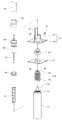
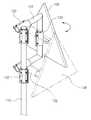
도 1은 본 발명의 제1실시예에 따른 충격흡수형 표지판의 사시도,
도 2는 도 1의 분해 사시도,
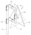
도 3a 내지 도 3d는 도 1에 나타낸 표지판재의 사용 상태도,
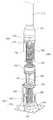
도 4는 본 발명의 제2실시예에 따른 충격흡수형 표지판의 일부 사시도,
도 5a와 도 5b는 도 4의 일부를 절개한 부분 분해 사시도.1 is a perspective view of a shock absorbing sign according to a first embodiment of the present invention;
Fig. 2 is an exploded perspective view of Fig. 1,
3A to 3D are diagrams showing a state of use of the sign material shown in FIG. 1,
4 is a partial perspective view of a shock absorbing sign according to a second embodiment of the present invention;
5A and 5B are partially exploded perspective views cut away from a portion of FIG. 4;
이하 본 발명의 실시예에 대하여 첨부된 도면을 참고로 그 구성 및 작용을 설명하기로 한다.Hereinafter, the configuration and operation of the present invention will be described with reference to the accompanying drawings.
도 1은 본 발명의 제1실시예에 따른 충격흡수형 표지판의 사시도이고, 도 2는 도 1의 분해 사시도이다.1 is a perspective view of a shock absorbing sign according to a first embodiment of the present invention, Figure 2 is an exploded perspective view of FIG.
도시된 바와 같이 본 발명의 제1실시예에 따른 충격흡수형 표지판(100)은 지주(110), 표지판재(120), 결속수단(130), 충격흡수수단(150)을 포함하여 구성된다.As shown, the shock-absorbing
지주(110)는 도로나 보차도 등과 같은 도로의 시설규정에 요구되는 지면에 지면과 수직되게 설치되고 둥근 관형상으로 이루어진다.The
상기 지주(110)는 상측지주(112)와 하측지주(111)로 분리되고 그 사이에 개재되어 상측지주(112)와 하측지주(111)를 결합하는 충격흡수수단(150)에 의해 외부의 충격을 흡수하고 충격 이후에 원위치로 복귀된다.The
상기 지주(110)의 상부에 결속수단(130)에 의해 결속되는 표지판재(120)는 금속판에 발광용 도료로 문자나 기호를 표시하여 이루어진다.
이 표지판재(120)에 표시되는 문자나 기호는 도로 이용자의 눈에 잘 띄도록 뚜렷해야 하며, 멀리서도 읽을 수 있는 크기여야 하고, 지명이나 거리?방향 등을 형광페인트로 표시하여 밤에도 잘 읽을 수 있어야 한다.Characters or symbols displayed on the
상기 결속수단(130)은 ㄷ자 형태의 결속구(131)와, 상기 결속구(131)를 지주(110)에 결속하는 제1결속클립(132)과, 상기 결속구(132)에 표지판재(120)를 결속하는 제2결속클립(133)으로 이루어진다.The binding means 130 is a
상기 ㄷ자 형태 결속구(131)의 개방된 상하 양측과 지주(110)에 제1결속클립(132)이 각각 끼워지고 각 제1결속클립(132)끼리는 땜이나 용접 등으로 고정되어 결속구(131)가 지주(110)에 결속된다.The first binding
또한, 상기 결속구(131)의 수직 부분에 끼워져 표지판재(120)를 고정하는 제2결속클립(133)은 상기 표지판재(120)에 결합된 결합대(121)에 볼트와 너트로 결합되거나 땜이나 용접 등에 의해 고정되어 결속구(131)에 표지판재(120)가 결속된다.In addition, the second binding
상기 제1,2결속클립(132,133)은 일측이 절개된 내부가 빈 둥근 형태로 내부에 결속구(131)나 지주(110)가 끼워진 상태에서 절개된 2개의 마주보는 조립편(134)에 볼트, 너트 등의 결합부재(135)가 결합되어 결속구(131)나 지주(110)에 결속된다.The first and second binding
상기 제1,2결속클립(132,133)은 결합부재(135)를 푸는 것에 의해 분리가 가능하여, 결속구(131)와 지주(110)에 결속시, 그 결속 위치를 조절함으로써 도로변 여건이나 도로 지반상황에 따라 유연하게 설치할 수 있다.The first and second binding clips (132, 133) can be separated by loosening the
또한, 상기 제1,2결속클립(132,133)은 상기 결속구(131)나 지주(110)에 완전 고정되는 것이 아니라, 슬라이드 형태로 상하나 좌우로 이동이 가능하고 회전할 수 있되, 수직으로 결속클립(132,133)이 결속된 경우 중력에 의해 아래로 처짐을 방지하기 위하여 상기 결속클립(132,133)와 지주(110)나 결속구(131) 사이의 하부에 고무링과 같은 마찰부재(136)를 끼워 지주(110)나 결속구(131)에 결속할 수 있다.In addition, the first and second binding
상기 충격흡수수단(150)의 와이어(151)는 서로 떨어진 상측지주(112)와 하측지주(111)의 중앙 부분을 약간의 텐션을 갖도록 연결하되, 와이어(151)의 하측은 하측지주(111)의 중심에서 상부로 돌출된 하측돌기(152)에 연결되고, 상기 하측돌기(152)의 바닥에는 흡수스프링(154)의 하부가 지지될 수 있도록 원형의 장착판(153)이 형성된다.The
상기 하측돌기(152)의 외측에 삽입되는 흡수스프링(154)은 내측스프링(155)과 외측스프링(156)의 2중 스프링으로 이루어지고 이에 따라 흡수스프링(154)의 하부를 지지되는 장착판(153)도 서로 다른 직경을 갖도록 2중으로 형성된다.
한편, 하측지주(111)에는 상하로 관통홀이 형성된 제1결합판(157)이 고정되고 이 제1결합판(157)에는 그 상부에 위치한 결합구(158)의 제2결합판(159)에 볼트/너트 등의 결합부재(161)에 결합된다.Meanwhile, a
상기 결합구(158)는 상하로 관통홀이 형성된 제2결합판(159) 상부에 고정관(160)이 결합되어 이루어지되, 고정관(160) 내에는 흡수스프링(154)이 위치되고 제2결합판(159)과 고정관(160)의 결합력을 높이기 위해 제2결합판(159) 상측과 고정관(160) 외측 사이에 보강리브(162)가 덧대어 진다.The
마찬가지로 제1결합판(157)과 하측지주(111)의 결합력을 높이기 위해 제1결합판(157) 하측과 하측지주(111) 사이에 보강리브(미도시)가 덧대어 질 수도 있다.Similarly, reinforcing ribs (not shown) may be padded between the lower side of the
상기 2중의 흡수스프링(154)의 상부와 후술하는 복원스프링(166)의 하부를 지지하는 매개구(163)의 하부도 서로 다른 직경을 갖도록 2중으로 형성되고 와어어(151)가 관통할 수 있도록 관통홀이 형성된다.The upper portion of the double absorbing
상기 결합구(158)의 고정관(160) 상부에는 제1스페이서(164)를 사이에 두고 유동관(165)이 위치하며, 이 유동관(165) 내에는 복원스프링(166)이 삽입된 상태에서 복원스프링(166)의 상부는 제2스페이서(167)에 지지되고 하부는 매개구(163)에 지지된다.The
한편, 고정관(160)의 일측에 지지대(168)가 용접 등에 의해 고정되게 결합된 상태에서 상측으로 돌출되게 형성하여 유동관(165)의 일측을 지지하게 하는 것이 바람직하다.On the other hand, the
상기 지지대(168)가 차도 측을 향하도록 지주(110)를 설치하면, 유동관(165)을 포함한 상측지주(112)가 차도 측으로 기울어지지 않도록 하여 사고를 미리 방지할 수 있다.When the
제2스페이서(167)는 상기 복원스프링(166)의 상부를 지지하면서 유동관(165)의 상부와 상측관(169)의 하부를 이격시키며 와이어(151)가 관통할 수 있도록 중앙의 상하로 관통홀이 형성된다.The
상기 상측관(169)은 상측지주(112)에 고정되게 결합되고 와이어(151)의 상부는 이 상측관(169)의 중앙을 관통하여 상측지주(112)의 하부에 연결된다.
The
이와 같이 중앙의 와이어(151)가 상측지주(112)와 하측지주(111)를 텐션을 갖도록 연결하고, 상기 와이어(151)의 외측에 삽입되어 하측의 흡수스프링(153)과 상측의 복원스프링(166)이 구비되며, 그 외측에 삽입되어 하측에서 상측으로 고정관(160)과 유동관(165), 유동관(165)과 상측관(166)이 제1스페이서(164)와 제2스페이서(167)에 의해 분리된 상태에서 상측지주(112)에 충격이 발생하는 경우 2중의 흡수스프링(154)이 충격이 발생한 반대 방향으로 기울어지면서 충격을 흡수하게 된다.In this way, the
이때 유동관(165)을 비롯한 상측지주(112)도 충격이 발생한 반대 방향으로 기울어지면서 충격을 흡수하여 인명 피해를 줄일 수 있고, 충격이 가해진 후 계속되는 외력이 없는 경우, 상측지주(112)는 하측지주(111)에 텐션을 갖도록 와이어(151)로 연결되고 흡수스프링(154) 및 복원스프링(166)의 복원력에 의해 상측지주(112)가 원래 위치로 복원되어 파손되지 않게 된다.At this time, the
또한 강풍이 부는 경우에는 강풍에 의해 지주(110)가 강풍이 부는 방향으로 기울어지면서 표지판(100)의 세로길이(높이)가 낮아지고, 강풍과 접하는 표지판재(120)의 면적이 줄어들어 표지판기초를 기존보다 작게 만들 수 있다.
In addition, when the strong wind is blowing, the vertical length (height) of the
도 3a 내지 도 3d는 도 1에 나타낸 표지판재의 사용 상태도이다.3A to 3D are use state diagrams of the sign material shown in FIG. 1.
도 3a는 지주(110)와 결속구(131)에 수직으로 결속된 제1결속클립(132)이 좌우로 회전하여 충격을 흡수할 수 있는 모습을 나타낸다.3a shows a state in which the first
도 3b는 표지판재(120)와 결합된 제2결속클립(133)이 좌우로 회전하여 표지판재(120)의 방향을 조절할 수 있는 모습을 나타낸다.3b shows a state in which the second
도 3c는 결속구(131)와 지주(110)에 결속된 제1결속클립(132)이 지주(110)에서 슬라이드 방식으로 승강하여 표지판재(120)의 높이를 조절하는 모습을 나타낸다.3c shows a state in which the first
도 3d는 결속구(131)에 수평으로 결속된 제1결속클립(132)에 의해 결속구(131)가 슬라이드 방식으로 좌우로 이동하여 표지판재(120)의 좌우 위치를 조절하는 모습을 나타낸다.3d illustrates a state in which the
이에 의해 나무나 외부 설치물 등과 같은 장애물이나, 도로의 보차도 경계석 및 각종 도로변의 여건으로 인하여 도로의 시설규정에 요구되는 위치에서도 설치할 수 있다.As a result, it can be installed at a position required for road facility regulation due to obstacles such as trees or external installations, road sidewalks, boundary stones, and various roadside conditions.
또한, 강풍이나 태풍과 같은 자연재해에도 표지판재(120)의 휘어짐이나, 파손을 방지할 수 있다.In addition, even when a natural disaster such as a strong wind or a typhoon, the bending and damage of the
그리고 수동으로 충격흡수형 표지판의 높이, 좌우 위치나 방향을 조절할 수 있으며, 차량의 진행방향과 표지판재(120)의 방향을 일치시켜 제2의 교통사고를 예방할 수 있다.
And the height of the shock-absorbing signs can be adjusted, the left and right position or direction, and the second traffic accident can be prevented by matching the direction of the vehicle and the direction of the
도 4는 본 발명의 제2실시예에 따른 충격흡수형 표지판의 일부 사시도이고, 도 5a와 도 5b는 도 4의 일부를 절개한 부분 분해 사시도이다.4 is a partial perspective view of a shock absorbing sign according to a second embodiment of the present invention, Figures 5a and 5b is a partially exploded perspective view of a portion of FIG.
도시된 바와 같이 본 발명의 제2실시예에 따른 충격흡수형 표지판(200)은 지주(210), 표지판재, 결속수단, 충격흡수수단(250)을 포함하여 구성되되, 표지판재와 결속수단의 구성과 작용은 제1실시예와 같으므로 여기서는 상세한 설명을 약한다.As shown, the shock-absorbing
지주(210)는 도로나 보차도 등과 같은 도로의 시설규정에 요구되는 지면에 지면과 수직되게 설치되고 둥근 관형상으로 이루어진다.The
상기 지주(210)는 충격흡수수단(250)을 통해 하부의 표지판기초(미도시) 상부에 수직되게 설치되고, 이 충격흡수수단(250)에 의해 외부의 충격을 흡수하고 충격 이후에 원위치로 복귀되어 지주(210)가 파손되는 것을 방지한다.The
상기 충격흡수수단(250)의 와이어(251)는 서로 떨어진 지주(210)와 표지판기초의 중앙 부분을 약간의 텐션을 갖도록 연결하되, 와이어(251)의 하측은 하측돌기(252)에 연결되고, 상기 하측돌기(252)는 표지판기초 상부에 결합되는 결합구(253)에 고정된다.The
더 상세하게는 상기 결합구(253))는 표지판기초에 결합되는 결합판(254)에 고정관(255)이 결합되어 이루어지고, 상기 하측돌기(252)는 고정관(255) 내측에 삽입되어 결합판(254)에 고정되고, 상기 하측돌기(252)의 바닥에는 하측돌기(252)의 외측에 삽입되는 복원스프링(256)이 장착될 수 있도록 원형의 장착판(257)이 형성된다.More specifically, the
이때 결합판(254)과 고정관(255)의 결합력을 높이기 위해 결합판(254) 상측과 고정관(255) 외측 사이에 보강리브(258)가 덧대어 진다.At this time, the reinforcing
상기 결합구(253)의 고정관(255) 상부에는 제1스페이서(259)를 사이에 두고 제1유동관(260)이 위치하며, 상기 복원스프링(256)의 상부는 제1스페이서(259)에 의해 지지된다.The
이때 고정관(255)의 일측에 지지대(261)가 용접 등에 의해 고정되게 결합된 상태에서 상측으로 돌출되게 형성하여 제1유동관(260)의 일측을 지지하게 하는 것이 바람직하다.At this time, it is preferable that the
상기 지지대(261)가 차도 측을 향하도록 지주(210)를 설치하면, 제1유동관(260)을 포함한 지주(210)가 차도 측으로 기울어지지 않도록 하여 사고를 미리 방지할 수 있다.When the
상기 제1유동관(260)의 상부에는 제2스페이서(262)를 사이에 두고 제2유동관(263)이 위치하며, 상기 제1유동관(260)과 제2유동관(263)의 내부에는 흡수스프링(264)이 삽입되되, 상기 흡수스프링(264)은 내측스프링(265)과 외측스프링(266)의 2중 스프링으로 이루어진다.A
이때 내측스프링(265)의 하부는 상대적으로 하부에 위치한 제1스페이서(259)에 지지되며, 외측스프링(266)의 하부는 상대적으로 상부에 위치한 제2스페이서(262)에 지지되어 내측스프링(265)은 제1,2유동관(260,263)을 걸쳐서 내부에 위치하고, 외측스프링(266)은 제2유동관(263)의 내부에 위치한다.At this time, the lower portion of the
상기 흡수스프링(264)의 상부를 지지하면서 제2유동관(263)과 상측관(267)을 구분하는 갭(268)은 관통공이 형성된 원형판(269)과 하측돌기(270)로 이루어지며, 상기 하측돌기(270)의 외측으로 흡수스프링(264)이 삽입되면서 상기 원형판(269)과 하측돌기(270)의 관통공을 와이어(251)가 관통하여 지주(210)에 고정되게 결합하는 상측관(267)을 통해 지주(210)에 연결된다.
The
이와 같이 와이어(251)가 지주(210)와 표지판기초를 텐션을 갖도록 연결하고, 상기 와이어(251)의 외측에 삽입되어 하측의 복원스프링(256)과 하측의 흡수스프링(264)이 구비되며, 그 외측에 삽입되어 하측에서 상측으로 고정관(255)과 제1유동관(260), 제1유동관(260)과 제2유동관(263), 제2유동관(2630과 상측관(267)이 제1스페이서(259), 제2스페이서(262) 및 갭(268)에 의해 분리된 상태에서 외부에서 지주(210)에 충격을 가하는 경우, 2중의 흡수스프링(261)이 충격이 발생한 반대 방향으로 기울어지면서 충격을 흡수하게 된다.As such, the
이때 제1유동관(260)을 비롯한 지주(210)도 충격이 발생한 반대 방향으로 기울어지면서 충격을 흡수하여 인명 피해를 줄일 수 있고 충격이 가해진 후, 계속되는 외력이 없는 경우 흡수스프링(264) 및 복원스프링(256)의 복원력에 의해 지주(210)가 원래 위치로 복원되어 파손되지 않게 된다.At this time, the
또한 강풍이 부는 경우에는 강풍에 의해 지주(210)가 강풍이 부는 방향으로 기울어지면서 표지판(100)의 세로길이(높이)가 낮아지고, 강풍과 접하는 표지판재의 면적이 줄어들어 표지판기초를 기존보다 작게 만들 수 있다.In addition, when strong winds blow, the vertical length (height) of the
100,200: 표지판110,210: 지주
120: 표지판재130: 결속수단
150,250: 충격흡수수단100,200: Sign 110,210: Holding
120: sign material 130: binding means
150,250: shock absorbing means
Claims (9)
Translated fromKorean상기 지주의 상부에 결속되고 금속판에 발광용 도료로 문자나 기호를 표시하여 이루어지는 표지판재;
ㄷ자 형태의 결속구와, 상기 결속구를 지주에 결속하는 제1결속클립과, 상기 결속구에 표지판재를 결속하는 제2결속클립으로 이루어지는 결속수단; 및
상기 상측지주와 하측지주 사이에 개재되어 결합하되, 중앙의 와이어에 의해 상측지주와 하측지주가 텐션을 갖도록 연결되고, 상기 와이어의 외측에 하측의 흡수스프링과 상측의 복원스프링이 구비되며, 상기 흡수스프링과 복원스프링의 외측에 하측에서 상측으로 하측지주에 결합되는 고정관, 유동관과 상측지주에 결합되는 상측관이 구비되어 제1스페이서와 제2스페이서에 의해 분리되는 충격흡수수단을 포함하는 충격흡수형 표지판.Shore consisting of upper and lower supporters vertically installed on the ground and separated up and down;
A sign material which is bound to an upper part of the support and displays a letter or a symbol with a light-emitting paint on a metal plate;
Binding means consisting of a c-shaped binding sphere, a first binding clip for binding the binding sphere to a support, and a second binding clip for binding a sign material to the binding sphere; And
Interposed between the upper column and the lower column is coupled to each other, the upper and lower column is connected to the tension by the central wire, the lower absorption spring and the upper restoring spring is provided on the outside of the wire, the absorption Shock absorbing type including a shock absorbing means is provided on the outside of the spring and the restoring spring is coupled to the lower column from the lower side to the upper column, the upper tube coupled to the flow tube and the upper column is separated by the first spacer and the second spacer sign.
상기 고정관은 하측지주의 상부에 결합되는 결합판의 상부에 결합되되, 결합판 상측과 고정관 외측 사이에 보강리브가 덧대어 지는 것을 특징으로 하는 충격흡수형 표지판.The method of claim 1,
The fixing tube is coupled to the upper portion of the coupling plate is coupled to the upper portion of the lower column, shock absorbing sign characterized in that the reinforcing rib is padded between the upper side of the coupling plate and the fixing tube.
상기 고정관의 일측에 지지대가 고정되게 결합된 상태에서 상측으로 돌출 형성되어 유동관의 일측을 지지하는 것을 특징으로 하는 충격흡수형 표지판.The method according to claim 1 or 2,
Shock absorption type signs characterized in that the support is formed on the one side of the fixed tube is protruded upwardly to support one side of the flow pipe.
상기 지주의 상부에 결속되고 금속판에 발광용 도료로 문자나 기호를 표시하여 이루어지는 표지판재;
ㄷ자 형태의 결속구와, 상기 결속구를 지주에 결속하는 제1결속클립과, 상기 결속구에 표지판재를 결속하는 제2결속클립으로 이루어지는 결속수단; 및
상기 표지판기초와 지주 사이에 개재되어 결합하되, 중앙의 와이어에 의해 표지판기초와 지주가 텐션을 갖도록 연결되고 상기 와이어의 외측에 하측의 복원스프링과 상측의 흡수스프링이 구비되며, 상기 복원스프링과 흡수스프링의 외측에 하측에서 상측으로 표지판기초에 결합되는 고정관, 제1유동관, 제2유동관과 지주에 결합되는 상측관이 구비되어 제1스페이서, 제2스페이서와 갭에 의해 분리되는 충격흡수수단을 포함하는 충격흡수형 표지판.Struts installed perpendicular to the foundation of the sign;
A sign material which is bound to an upper part of the support and displays a letter or a symbol with a light-emitting paint on a metal plate;
Binding means consisting of a c-shaped binding sphere, a first binding clip for binding the binding sphere to a support, and a second binding clip for binding a sign material to the binding sphere; And
Is interposed between the sign base and the strut, coupled, the center of the sign base and the strut is connected to have a tension and the restoring spring of the lower side and the upper absorption spring is provided on the outside of the wire, the restoring spring and absorption A fixed tube coupled to the base of the sign from the lower side to the outer side of the spring, the first flow tube, the upper side tube is coupled to the second flow tube and the support is provided with a shock absorbing means separated by the first spacer, the second spacer and the gap Shock-absorbing signs.
상기 고정관은 표지판기초에 결합되는 결합판의 상부에 결합되되, 결합판 상측과 고정관 외측 사이에 보강리브가 덧대어 지는 것을 특징으로 하는 충격흡수형 표지판.The method of claim 4, wherein
The fixing tube is coupled to the upper portion of the coupling plate coupled to the base of the sign, shock absorbing sign characterized in that the reinforcing rib is padded between the upper side of the coupling plate and the fixed tube.
상기 고정관의 일측에 지지대가 고정되게 결합된 상태에서 상측으로 돌출 형성되어 제1유동관의 일측을 지지하는 것을 특징으로 하는 충격흡수형 표지판.The method according to claim 4 or 5,
Shock absorbing type signs characterized in that the support is formed on the one side of the fixed tube is protruded upwardly to support one side of the first flow tube.
상기 흡수스프링은 내측스프링과 외측스프링의 2중 스프링으로 이루어지는 것을 특징으로 하는 충격흡수형 표지판.The method according to claim 1 or 4,
The absorbing spring is shock-absorbing sign, characterized in that consisting of a double spring of the inner spring and the outer spring.
상기 제1,2결속클립은 일측이 절개된 관통된 형태로 내부에 결속구나 지주가 끼워진 상태에서 절개된 2개의 마주보는 조립편에 결합부재가 결합되어 결속구나 지주에 결속되는 것을 특징으로 하는 충격흡수형 표지판.The method according to claim 1 or 4,
The first and second binding clips are shock-resistant, characterized in that the coupling member is coupled to the two opposite assembly pieces cut in a state in which the binding or support is inserted in a penetrated form in which one side is cut and bound to the binding or support. Absorbent signs.
상기 제1,2결속클립이 수직으로 결속된 경우 제1,2결속클립과 지주나 결속구 사이의 하부에 마찰부재가 끼워지는 것을 특징으로 하는 충격흡수형 표지판.The method of claim 8,
When the first and second binding clips are vertically bound, the shock absorbing sign, characterized in that the friction member is fitted to the lower portion between the first and second binding clips and the support or the binding port.
Priority Applications (1)
| Application Number | Priority Date | Filing Date | Title |
|---|---|---|---|
| KR1020110006776AKR101196702B1 (en) | 2011-01-24 | 2011-01-24 | Shock absorption type traffic sign |
Applications Claiming Priority (1)
| Application Number | Priority Date | Filing Date | Title |
|---|---|---|---|
| KR1020110006776AKR101196702B1 (en) | 2011-01-24 | 2011-01-24 | Shock absorption type traffic sign |
Publications (2)
| Publication Number | Publication Date |
|---|---|
| KR20120085449A KR20120085449A (en) | 2012-08-01 |
| KR101196702B1true KR101196702B1 (en) | 2012-11-19 |
Family
ID=46871677
Family Applications (1)
| Application Number | Title | Priority Date | Filing Date |
|---|---|---|---|
| KR1020110006776AExpired - Fee RelatedKR101196702B1 (en) | 2011-01-24 | 2011-01-24 | Shock absorption type traffic sign |
Country Status (1)
| Country | Link |
|---|---|
| KR (1) | KR101196702B1 (en) |
Cited By (1)
| Publication number | Priority date | Publication date | Assignee | Title |
|---|---|---|---|---|
| KR101511066B1 (en) | 2014-05-29 | 2015-04-13 | 주식회사 시온시스 | Apparatus for supporting the road managing device |
Families Citing this family (3)
| Publication number | Priority date | Publication date | Assignee | Title |
|---|---|---|---|---|
| CN112447096B (en)* | 2020-12-26 | 2022-08-02 | 义乌市巨界机械设备有限公司 | Put in formula car warning tripod |
| KR102516667B1 (en)* | 2021-10-28 | 2023-03-30 | 김준형 | Attached type LED traffic sign structure |
| KR102516668B1 (en)* | 2021-10-28 | 2023-03-30 | 김준형 | No-welding type LED traffic sign structure |
Citations (2)
| Publication number | Priority date | Publication date | Assignee | Title |
|---|---|---|---|---|
| JP2000322692A (en) | 1999-05-12 | 2000-11-24 | Shigemi Saito | Buffering device for road sign pole |
| JP2004197480A (en) | 2002-12-20 | 2004-07-15 | Hoan Kogyo Kk | Sign fixture |
- 2011
- 2011-01-24KRKR1020110006776Apatent/KR101196702B1/ennot_activeExpired - Fee Related
Patent Citations (2)
| Publication number | Priority date | Publication date | Assignee | Title |
|---|---|---|---|---|
| JP2000322692A (en) | 1999-05-12 | 2000-11-24 | Shigemi Saito | Buffering device for road sign pole |
| JP2004197480A (en) | 2002-12-20 | 2004-07-15 | Hoan Kogyo Kk | Sign fixture |
Cited By (1)
| Publication number | Priority date | Publication date | Assignee | Title |
|---|---|---|---|---|
| KR101511066B1 (en) | 2014-05-29 | 2015-04-13 | 주식회사 시온시스 | Apparatus for supporting the road managing device |
Also Published As
| Publication number | Publication date |
|---|---|
| KR20120085449A (en) | 2012-08-01 |
Similar Documents
| Publication | Publication Date | Title |
|---|---|---|
| US8282082B2 (en) | Impact absorbing barrier assembly | |
| US3902818A (en) | Portable traffic sign and base therefor | |
| KR101196702B1 (en) | Shock absorption type traffic sign | |
| KR101742292B1 (en) | Support device for post | |
| KR101358426B1 (en) | The post structure of traffic signal | |
| KR20130000173U (en) | Integrated Road Traffic Equipment | |
| KR101272869B1 (en) | Multi-function guide post | |
| KR101197144B1 (en) | A device for shock absorption and revolving pillar traffic sign | |
| KR102305527B1 (en) | Wind load matching type road sign device | |
| KR20190003183U (en) | mounting apparatus of traffic safety sign board for temporary facilities | |
| KR101088869B1 (en) | Variable fence | |
| JP6290140B2 (en) | Road protection facility with safety parts for warning and safety parts for warning | |
| KR100859660B1 (en) | Strut fixing base of road facility | |
| CN107815993B (en) | V-shaped road traffic safety guardrail | |
| CN205348049U (en) | Road pile is separated to two -way lane for bridge | |
| KR20110031554A (en) | Guard fence with cushioning function | |
| KR20190142621A (en) | mounting apparatus of traffic safety sign board for guard rail | |
| KR20160057272A (en) | In the event of a traffic accident, it is designed to minimize the casualties caused by human accidents, which are combined with facilities for safety of traffic accidents including street light landing pillar, road sign pillar, interrupted camera pillar, traffic signal pillar, electric power pole, Prevention of joints | |
| CN211735179U (en) | Municipal administration guardrail with shock-absorbing function | |
| KR101057721B1 (en) | Detachable street lamp struts that prevent cables from overturning by inserting cables into the extrusion column | |
| CN205242293U (en) | Pressure warning profile mark is prevented bumping in luminous reflection of light of country road | |
| KR101053103B1 (en) | Detachable street light struts that prevent cables from overturning by inserting cables into steel pillars | |
| KR101311383B1 (en) | Post assembly for hanging signal lamp with Pedestrian signal lanp | |
| KR20200014058A (en) | Safety fence | |
| CN214061411U (en) | Rural highway rail guard |
Legal Events
| Date | Code | Title | Description |
|---|---|---|---|
| A201 | Request for examination | ||
| PA0109 | Patent application | St.27 status event code:A-0-1-A10-A12-nap-PA0109 | |
| PA0201 | Request for examination | St.27 status event code:A-1-2-D10-D11-exm-PA0201 | |
| D13-X000 | Search requested | St.27 status event code:A-1-2-D10-D13-srh-X000 | |
| D14-X000 | Search report completed | St.27 status event code:A-1-2-D10-D14-srh-X000 | |
| E701 | Decision to grant or registration of patent right | ||
| PE0701 | Decision of registration | St.27 status event code:A-1-2-D10-D22-exm-PE0701 | |
| PG1501 | Laying open of application | St.27 status event code:A-1-1-Q10-Q12-nap-PG1501 | |
| GRNT | Written decision to grant | ||
| N231 | Notification of change of applicant | ||
| PN2301 | Change of applicant | St.27 status event code:A-5-5-R10-R13-asn-PN2301 St.27 status event code:A-5-5-R10-R11-asn-PN2301 | |
| PR0701 | Registration of establishment | St.27 status event code:A-2-4-F10-F11-exm-PR0701 | |
| PR1002 | Payment of registration fee | St.27 status event code:A-2-2-U10-U11-oth-PR1002 Fee payment year number:1 | |
| PG1601 | Publication of registration | St.27 status event code:A-4-4-Q10-Q13-nap-PG1601 | |
| LAPS | Lapse due to unpaid annual fee | ||
| PC1903 | Unpaid annual fee | St.27 status event code:A-4-4-U10-U13-oth-PC1903 Not in force date:20151027 Payment event data comment text:Termination Category : DEFAULT_OF_REGISTRATION_FEE | |
| P22-X000 | Classification modified | St.27 status event code:A-4-4-P10-P22-nap-X000 | |
| PC1903 | Unpaid annual fee | St.27 status event code:N-4-6-H10-H13-oth-PC1903 Ip right cessation event data comment text:Termination Category : DEFAULT_OF_REGISTRATION_FEE Not in force date:20151027 | |
| P22-X000 | Classification modified | St.27 status event code:A-4-4-P10-P22-nap-X000 | |
| P22-X000 | Classification modified | St.27 status event code:A-4-4-P10-P22-nap-X000 |