KR101193644B1 - Vaporizing and inhaling apparatus - Google Patents
Vaporizing and inhaling apparatusDownload PDFInfo
- Publication number
- KR101193644B1 KR101193644B1KR1020110053564AKR20110053564AKR101193644B1KR 101193644 B1KR101193644 B1KR 101193644B1KR 1020110053564 AKR1020110053564 AKR 1020110053564AKR 20110053564 AKR20110053564 AKR 20110053564AKR 101193644 B1KR101193644 B1KR 101193644B1
- Authority
- KR
- South Korea
- Prior art keywords
- vaporization
- vaporized
- liquefied
- vaporizing
- solid form
- Prior art date
- Legal status (The legal status is an assumption and is not a legal conclusion. Google has not performed a legal analysis and makes no representation as to the accuracy of the status listed.)
- Expired - Fee Related
Links
Images


Classifications
- A—HUMAN NECESSITIES
- A24—TOBACCO; CIGARS; CIGARETTES; SIMULATED SMOKING DEVICES; SMOKERS' REQUISITES
- A24F—SMOKERS' REQUISITES; MATCH BOXES; SIMULATED SMOKING DEVICES
- A24F40/00—Electrically operated smoking devices; Component parts thereof; Manufacture thereof; Maintenance or testing thereof; Charging means specially adapted therefor
- A24F40/40—Constructional details, e.g. connection of cartridges and battery parts
- A—HUMAN NECESSITIES
- A24—TOBACCO; CIGARS; CIGARETTES; SIMULATED SMOKING DEVICES; SMOKERS' REQUISITES
- A24B—MANUFACTURE OR PREPARATION OF TOBACCO FOR SMOKING OR CHEWING; TOBACCO; SNUFF
- A24B15/00—Chemical features or treatment of tobacco; Tobacco substitutes, e.g. in liquid form
- A24B15/10—Chemical features of tobacco products or tobacco substitutes
- A24B15/16—Chemical features of tobacco products or tobacco substitutes of tobacco substitutes
- A24B15/167—Chemical features of tobacco products or tobacco substitutes of tobacco substitutes in liquid or vaporisable form, e.g. liquid compositions for electronic cigarettes
- A—HUMAN NECESSITIES
- A24—TOBACCO; CIGARS; CIGARETTES; SIMULATED SMOKING DEVICES; SMOKERS' REQUISITES
- A24F—SMOKERS' REQUISITES; MATCH BOXES; SIMULATED SMOKING DEVICES
- A24F40/00—Electrically operated smoking devices; Component parts thereof; Manufacture thereof; Maintenance or testing thereof; Charging means specially adapted therefor
- A24F40/10—Devices using liquid inhalable precursors
- A—HUMAN NECESSITIES
- A24—TOBACCO; CIGARS; CIGARETTES; SIMULATED SMOKING DEVICES; SMOKERS' REQUISITES
- A24F—SMOKERS' REQUISITES; MATCH BOXES; SIMULATED SMOKING DEVICES
- A24F40/00—Electrically operated smoking devices; Component parts thereof; Manufacture thereof; Maintenance or testing thereof; Charging means specially adapted therefor
- A24F40/20—Devices using solid inhalable precursors
- A—HUMAN NECESSITIES
- A61—MEDICAL OR VETERINARY SCIENCE; HYGIENE
- A61M—DEVICES FOR INTRODUCING MEDIA INTO, OR ONTO, THE BODY; DEVICES FOR TRANSDUCING BODY MEDIA OR FOR TAKING MEDIA FROM THE BODY; DEVICES FOR PRODUCING OR ENDING SLEEP OR STUPOR
- A61M15/00—Inhalators
- A61M15/06—Inhaling appliances shaped like cigars, cigarettes or pipes
Landscapes
- Health & Medical Sciences (AREA)
- Engineering & Computer Science (AREA)
- Biomedical Technology (AREA)
- Heart & Thoracic Surgery (AREA)
- Chemical Kinetics & Catalysis (AREA)
- Bioinformatics & Cheminformatics (AREA)
- Pulmonology (AREA)
- Anesthesiology (AREA)
- Chemical & Material Sciences (AREA)
- General Chemical & Material Sciences (AREA)
- Hematology (AREA)
- Life Sciences & Earth Sciences (AREA)
- Animal Behavior & Ethology (AREA)
- General Health & Medical Sciences (AREA)
- Public Health (AREA)
- Veterinary Medicine (AREA)
- Manufacture Of Tobacco Products (AREA)
- Disinfection, Sterilisation Or Deodorisation Of Air (AREA)
Abstract
Translated fromKoreanDescription
Translated fromKorean본 발명은 기화 흡입 장치에 관한 것으로서, 더욱 상세히는 내부에 수용된 기화 대상체를 기화시켜 사용자가 흡입할 수 있도록 하는 기화 흡입 장치에 관한 것이다.The present invention relates to a vaporization suction device, and more particularly to a vaporization suction device that allows a user to inhale by vaporizing the vaporization object accommodated therein.
기화 흡입 장치는 내부에 소정의 기화 대상체를 함유한 필터를 내장하여, 그 필터 내의 기화 대상체를 기화기를 통해 기화시켜 사용자가 흡입할 수 있도록 하는 장치이다.The vaporization suction device is a device having a filter containing a predetermined vaporization object therein, and vaporizing the vaporization object in the filter through a vaporizer so that a user can inhale.
이러한 기화 흡입 장치 내에는 니코틴 액, 건강 보조 성분이 함유된 액체 등의 기화 대상체가 수용될 수 있다. 그 대표적인 기화 흡입 장치로는 내부에 니코틴 액을 수용한 전자 담배가 있다.The vaporization inhalation device may contain a vaporization object such as a nicotine liquid, a liquid containing a health supplement component, and the like. A typical vaporization suction device is an electronic cigarette containing nicotine liquid inside.
최근 금연 보조용으로 담배 잎 가루를 종이로 말아놓은 실제 담배와 유사한 전자 담배의 이용이 늘어나고 있다.Recently, the use of electronic cigarettes similar to real cigarettes, which are made of paper dusted tobacco leaf powder, is increasing.
사용자가 실제 담배를 피울 때처럼 전자 담배를 입에 물고 흡입을 하게 되면, 전자 담배의 노출된 말단에서는 실제 담배에서 발생되는 불꽃과 유사한 불빛이 발생되고, 전자 담배의 사용자 입 내부의 말단에서는 실제 담배에서 발생되는 연기와 유사한 연기가 발생된다. 따라서, 이러한 전자 담배를 이용하면, 사용자는 실제 담배를 피우는 것과 유사한 느낌을 가질 수 있게 된다.If the user inserts the electronic cigarette into the mouth and sucks the same as when the user actually feels smoking, the exposed end of the electronic cigarette produces a light similar to that of a real cigarette, A smoke similar to the smoke generated in the combustion chamber is generated. Thus, with such an electronic cigarette, the user can have a feeling similar to smoking a real cigarette.
상기와 같은 전자 담배는 신체에 해로운 타르를 함유하지 아니하고, 담배의 유효 성분인 니코틴만 함유하고 있으므로, 사용자에게 담배 사용의 만족감을 주면서도 사용자의 신체에 가해지는 해로움을 최소화할 수 있다.Since the electronic cigarette does not contain tar harmful to the body but contains only nicotine, which is an effective component of the cigarette, harmfulness to the user's body can be minimized while giving the user satisfaction of using the cigarette.
일반적으로 전자 담배는 다수 개의 부재로 분할되고, 그 부재 중 제일 앞쪽의 부재 내에 발광 다이오드, 배터리, 회로 기판 및 흡입 감지 스위치가 수용되고, 그 다음 부재 내에 연기 제조 장치가 수용되며, 그 다음 부재 내에 니코틴 액을 함유한 필터가 수용된다.In general, the electronic cigarette is divided into a plurality of members, in which the light emitting diode, the battery, the circuit board and the suction detection switch are accommodated in the frontmost member, in which the smoke manufacturing apparatus is received, and then in the member. Filters containing nicotine liquid are accommodated.
상기 연기 제조 장치는 필터와 접촉되어 필터로부터 니코틴 액이 스며드는 액체 유도체와, 그 액체 유도체에 스며든 니코틴 액을 가열하여 기화시키는 기화 부재로 구성된다.The smoke producing apparatus comprises a liquid derivative contacting with a filter and permeating the nicotine solution from the filter, and a vaporizing member for vaporizing and heating the nicotine solution impregnated in the liquid derivative.
상기 흡입 감지 스위치는 사용자가 전자 담배를 물고 흡입하는지 여부를 그 기류 변화에 의해 감지하는 것이다.The inhalation detection switch detects whether the user inhales the electronic cigarette by the change of the airflow.
그러나, 종래의 전자 담배에서는, 기화 대상체로 니코틴 액 등 액체를 기화시키기 위한 구조를 이루고 있어서, 고체 형태의 기화 대상체를 기화시키기 곤란할 수 있는 단점이 있다.However, in the conventional electronic cigarette, there is a disadvantage in that it is difficult to vaporize the vaporized object in the solid form, since the vaporized object has a structure for vaporizing a liquid such as nicotine liquid.
본 발명은 고체 형태의 기화 대상체를 기화시킬 수 있는 구조를 가진 기화 흡입 장치를 제공하는 것을 일 목적으로 한다.It is an object of the present invention to provide a vaporization inhalation device having a structure capable of vaporizing a vaporized object in solid form.
본 발명의 일 측면에 따른 기화 흡입 장치는 사용자가 흡입할 수 있도록 내부에 수용된 기화 대상체를 흡입 대상 기체로 기화할 수 있는 것으로서,The vaporization suction device according to an aspect of the present invention is to vaporize the vaporization object accommodated therein to the inhalation target gas for the user to inhale,
고체 형태의 상기 기화 대상체를 수용하는 기화 대상체 수용 부재; 및 상기 기화 대상체 수용 부재에 수용된 고체 형태의 상기 기화 대상체를 액화 및 기화시키는 액화 기화 부재;를 포함하고,
상기 액화 기화 부재는 상기 기화 대상체 수용 부재에 수용된 고체 형태의 상기 기화 대상체를 액화시키는 액화 부재와, 상기 액화 부재에 의해 액화된 상기 기화 대상체를 기화시키는 기화 부재로 구성되고,
상기 수용 부재에 수용된 고체 형태의 상기 기화 대상체는 상기 액화 부재와 상기 기화 부재를 경유하면서, 순차적으로 액화 및 기화되는 것을 특징으로 한다.A vaporized object receiving member for receiving the vaporized object in solid form; And a liquefied vaporization member configured to liquefy and vaporize the vaporized object in a solid form accommodated in the vaporized object receiving member.
The liquefied vaporizing member is composed of a liquefied member for liquefying the vaporized object in the solid form accommodated in the vaporized object receiving member, and a vaporized member for vaporizing the vaporized object liquefied by the liquefied member,
The vaporized object in the solid form accommodated in the receiving member is liquefied and vaporized sequentially while passing through the liquefied member and the vaporized member.
본 발명의 일 측면에 따른 기화 흡입 장치에 의하면, 고체 형태로 기화 대상체 수용 부재 내에 수용된 기화 대상체가 액화 부재에 의해 1차적으로 액화되고, 상기와 같이 액화된 기화 대상체가 기화 부재를 거치면서 2차적으로 기화되어 사용자가 흡입할 수 있는 상태가 됨에 따라, 고체 형태의 기화 대상체에 대한 기화 흡입이 가능할 수 있는 효과가 있다.According to the vaporization suction device according to an aspect of the present invention, the vaporized object accommodated in the vaporized object receiving member in the solid form is primarily liquefied by the liquefied member, and the liquefied vaporized object as described above is subjected to secondary As it is vaporized to the user can be inhaled, there is an effect that the inhalation of vaporization for the vaporized subject in the solid form is possible.
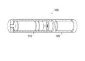
도 1은 본 발명의 제 1 실시예에 따른 기화 흡입 장치가 분리된 모습을 보이는 사시도.
도 2는 본 발명의 제 1 실시예에 따른 기화 흡입 장치가 결합된 모습을 보이는 사시도.
도 3은 본 발명의 제 1 실시예에 따른 기화 흡입 장치의 제 2 분할 부재의 구성을 보이는 단면도.
도 4는 본 발명의 제 1 실시예에 따른 기화 흡입 장치의 제 2 분할 부재에서 기화 대상체가 감소되었을 때의 모습을 보이는 단면도.
도 5는 본 발명의 제 2 실시예에 따른 기화 흡입 장치의 제 2 분할 부재의 구성을 보이는 단면도.
도 6은 본 발명의 제 2 실시예에 따른 기화 흡입 장치의 제 2 분할 부재에서 기화 대상체가 감소되었을 때의 모습을 보이는 단면도.1 is a perspective view showing a state in which the vaporization suction device according to the first embodiment of the present invention is separated.
2 is a perspective view showing a state in which the vaporization suction device according to the first embodiment of the present invention is coupled.
3 is a cross-sectional view showing the configuration of a second partition member of the vaporization suction apparatus according to the first embodiment of the present invention.
Figure 4 is a cross-sectional view showing the appearance when the vaporization object is reduced in the second partition member of the vaporization suction apparatus according to the first embodiment of the present invention.
5 is a cross-sectional view showing the configuration of a second partition member of the vaporization suction apparatus according to the second embodiment of the present invention.
6 is a cross-sectional view showing the appearance of when the vaporization object is reduced in the second partition member of the vaporization suction apparatus according to the second embodiment of the present invention.
본 실시예들에서는 기화 흡입 장치로 내부에 니코틴 액을 수용한 전자 담배(electronic cigarette) 방식의 장치가 제시되나, 이는 예시적인 것이다. 즉, 이하에서 설명되는 기화 흡입 장치 내에 수용되는 기화 대상체로는 니코틴 액 대신 주사액, 아로마 등의 각종 향료, 기능성 성분 포함 물질, 건강 보조 성분 포함 물질, 의약 성분 포함 물질 등이 제시될 수 있다. 이러한 기화 대상체가 기화 흡입 장치 내에서 기화됨으로써 사용자에게 흡입될 수도 있다. 이러한 경우, 아래의 발광 다이오드 등의 구성 요소는 필요에 따라 생략될 수도 있을 것이다.In the present embodiments, there is provided an electronic cigarette type device in which nicotine liquid is received as a vaporization suction device, but this is exemplary. That is, the vaporization object accommodated in the vaporization inhalation apparatus described below may be presented with various flavors such as injection liquids, aromas, functional ingredient-containing substances, health supplement-containing substances, pharmaceutical ingredient-containing substances, and the like instead of nicotine liquid. Such a vaporized object may be inhaled by a user by being vaporized in a vaporization inhalation device. In such a case, the following components such as the light emitting diode may be omitted as needed.
도 1은 본 발명의 제 1 실시예에 따른 기화 흡입 장치가 분리된 모습을 보이는 사시도이고, 도 2는 본 발명의 제 1 실시예에 따른 기화 흡입 장치가 결합된 모습을 보이는 사시도이고, 도 3은 본 발명의 제 1 실시예에 따른 기화 흡입 장치의 제 2 분할 부재의 구성을 보이는 단면도이고, 도 4는 본 발명의 제 1 실시예에 따른 기화 흡입 장치의 제 2 분할 부재에서 기화 대상체가 감소되었을 때의 모습을 보이는 단면도이다.1 is a perspective view showing the separated vaporization suction apparatus according to a first embodiment of the present invention, Figure 2 is a perspective view showing a combined vaporization suction apparatus according to a first embodiment of the present invention, Figure 3 Is a cross-sectional view showing the configuration of the second partition member of the vaporization suction device according to the first embodiment of the present invention, Figure 4 is a reduced vaporization object in the second partition member of the vaporization suction device according to the first embodiment of the present invention Here is a cross-sectional view of what it looks like.
도 1 내지 도 4를 함께 참조하면, 본 실시예에 따른 기화 흡입 장치(100)는 제 1 분할 부재(110)와, 제 2 분할 부재(120)를 포함하고, 사용자가 흡입할 수 있도록 내부에 수용된 기화 대상체(162)를 흡입 대상 기체로 기화할 수 있는 것이다.1 to 4 together, the
여기서, 상기 기화 흡입 장치(100)가 상기 제 1 분할 부재(110)와 상기 제 2 분할 부재(120)로 구성되는 것으로 제시되나, 이는 예시적인 것이고, 상기 기화 흡입 장치(100)는 더 많은 개수의 분할 부재로 분할될 수도 있고, 그러한 복수 개의 분할 부재 내에 상기 기화 대상체(162)를 상기 흡입 대상 기체로 기화시키기 위한 구성 요소들이 분할되어 수용될 수 있다.Here, the
상기 제 1 분할 부재(110)의 케이스(111) 내에는 발광 다이오드(113), 발광부(130), 배터리(115), 제어부(114) 및 흡입 감지 스위치(150)가 배치된다.The
상기 제 2 분할 부재(120)의 케이스(121) 내에는 기화 부재(170), 기화 대상체 수용 부재(160) 및 뚜껑(124)이 배치된다.The
여기서, 상기 제 1 분할 부재(110)의 케이스(111)는 전측 케이스로, 상기 제 2 분할 부재(120)의 케이스(121)는 후측 케이스로 정의될 수 있다.Here, the
상기 발광 다이오드(113)는 상기 배터리(115)에 전기적으로 연결되어, 붉은 색으로 발광할 수 있는 부분이다. 이러한 발광 다이오드(113)는 케이스(111) 전면의 전면 부재(112)에 형성된다. 상기 발광부(130)는 상기 발광 다이오드(113)와 연결되어, 상기 제어부(114)의 제어에 따라 상기 발광 다이오드(113)를 발광시킨다.The
상기 배터리(115)는 상기 발광 다이오드(113), 상기 제어부(114), 상기 기화 부재(170) 등에 전원을 인가하는 부분으로, 폴리머 리튬 전지 등이 제시될 수 있다.The
상기 제어부(114)는 상기 기화 흡입 장치(100)의 작동을 위해 요구되는 각종 회로가 형성된 부분이다. 이러한 제어부(114)는 상기 흡입 감지 스위치(150)에서 전달된 감지값에 따라 상기 발광 다이오드(113), 상기 기화 부재(170) 등의 작동을 제어할 수 있다.The
상기 케이스(111)의 후측 말단에는 부압 형성부(116)가 형성된다. 상기 부압 형성부(116)에는 외기 도입 홀(117)이 형성된다. 상기 외기 도입 홀(117)은 복수 개 형성될 수 있다. 상기 외기 도입 홀(117)은 외기 도입부로 정의될 수 있다.A negative
사용자가 흡입을 하면, 상기 부압 형성부(116) 내의 공기가 상기 제 2 분할 부재(120)를 통해 사용자의 입 속으로 유입되고, 그에 따라 상기 부압 형성부(116)에 부압(負壓)이 형성되고, 그에 따라 상기 외기 도입 홀(117)을 통해 외기가 상기 부압 형성부(116)로 유입된다.When the user inhales, air in the negative
사용자가 흡입 시에 상기 외기 도입 홀(117)을 통해 상기 부압 형성부(116)로 도입되는 외기는 상기 기화 부재(170)에 의해 기화된 흡입 대상 기체인 니코틴과 함께 사용자에게 흡입된다.When the user inhales, the outside air introduced into the negative
상기 흡입 감지 스위치(150)는 사용자가 상기 제 2 분할 부재(120)의 말단부를 입으로 물고 흡입을 할 때, 그러한 흡입 여부를 감지하는 부분이다.The
상기 흡입 감지 스위치(150)가 사용자의 흡입을 감지하면, 상기 제어부(114)는 상기 기화 대상체 수용 부재(160) 내의 액체가 기화되도록, 상기 기화 부재(170)를 작동시킨다.When the
상기 제 2 분할 부재(120)의 전측에는 삽입체(122)가 형성된다. 상기 삽입체(122)는 상기 부압 형성부(116)의 말단에 삽입된다. 상기 삽입체(122)가 상기 부압 형성부(116)에 삽입되더라도, 상기 외기 도입 홀(117)은 상기 삽입체(122)에 의해 가려지지 아니한다. 그리고, 상기 삽입체(122)는 상기 배터리(115) 및 상기 제어부(114)와 전기적으로 연결된다. 예를 들어, 상기 삽입체(122)의 외면과 상기 부압 형성부(116)의 내면에 서로 맞닿는 전극이 형성되고, 상기 삽입체(122)의 외면에 형성된 전극은 상기 액화 부재(165) 및 상기 기화 부재(170)와 전기적으로 연결되고, 상기 부압 형성부(116)의 내면에 형성된 전극은 상기 제어부(114) 및 상기 배터리(115)와 전기적으로 연결될 수 있다.An
상기 삽입체(122)의 중앙부에는 외기 유동 홀(123)이 형성된다. 상기 외기 유동 홀(123)을 통해 상기 부압 형성부(116) 내의 공기가 상기 제 2 분할 부재(120) 케이스(121) 내부로 유입될 수 있다. 상기와 같이 유입된 공기는 상기 기화 부재(170)를 거쳐 상기 뚜껑(124)에 형성된 흡입 홀(121d)을 통해 사용자의 입으로 유출된다.The outside
상기 외기 유동 홀(123) 주변부(127)의 주변에는 함몰된 형태의 함몰부(128)가 형성되고, 상기 함몰부(128)의 주변에는 상기 삽입체(122)의 외곽부(129)가 형성된다.A
상기 기화 대상체 수용 부재(160)는 상기 제 2 분할 부재(120)의 케이스(121) 내에 교환 가능하게 삽입될 수 있는 것으로, 고체 형태의 기화 대상체(162)를 수용한다.The vaporization
여기서, 상기 기화 대상체(162)는 분말 등의 형태로 고체 형태를 이룰 수 있다.Here, the
상기 기화 대상체 수용 부재(160)는 수용 부재 몸체(161)와, 푸싱 부재(163)와, 탄성 부재(164)를 포함한다. 상기 기화 대상체 수용 부재(160) 내에는 액화 부재(165)가 배치될 수 있다. 상기 액화 부재(165)가 상기 기화 대상체 수용 부재(160) 내에 배치되는 것은 예시적인 것이다.The vaporization
상기 수용 부재 몸체(161)는 상기 기화 대상체(162)가 내부에 수용되는 것이고, 상기 푸싱 부재(163)는 상기 수용 부재 몸체(161)를 따라 이동되면서 상기 액화 부재(165) 쪽으로 상기 기화 대상체(162)를 밀어주는 것이다. 상기 탄성 부재(164)는 상기 푸싱 부재(163)의 후방에서 상기 푸싱 부재(163)에 탄성을 가하여, 상기 푸싱 부재(163)가 상기 수용 부재 몸체(161)를 따라 이동되면서 상기 액화 부재(165) 쪽으로 상기 기화 대상체(162)를 밀도록 한다. 이러한 탄성 부재(164)로 스프링 등이 제시될 수 있으나, 이는 예시적인 것이고, 다양한 탄성체가 적용될 수 있다.The receiving
상기 액화 부재(165)는 액화 부재 연결 도선(121e)을 통해 상기 제어부(114) 및 상기 배터리(115)와 전기적으로 연결되는 것으로, 상기 흡입 감지 스위치(150)에서 흡입이 감지되는 경우, 발열하면서 그 부근에 있는 고체 형태의 상기 기화 대상체(162)를 액화시킨다.The
상기 액화 부재 연결 도선(121e)은 상기 삽입체(122) 등을 통해 상기 제어부(114) 및 상기 배터리(115)와 전기적으로 연결될 수 있다.The liquefaction
상기 액화 부재(165)에 의해 액화된 상기 기화 대상체(162)는 상기 기화 부재(170)의 몸체(171)와 상기 기화 대상체 수용 부재 몸체(161)를 함께 관통한 흡수체(174)에 의해 흡수되어, 상기 기화 부재 몸체(171)로 유입된다.The
상기 기화 부재 몸체(171) 내부로 유입된 액화된 상기 기화 대상체(162)는 상기 기화 부재 몸체(171) 내에 형성된 기화 발열 부재(173)에 의해 기화된다. 상기 기화 발열 부재(173)는 상기 제어부(114)의 명령에 따라 상기 배터리(115)로부터 전원을 공급받아 발열할 수 있는 부분이다. 상기 기화 발열 부재(173)가 발열하면, 그 열에 의해 상기 기화 대상체 수용 부재(160)에서 전달된 액화된 기화 대상체(162)가 기화될 수 있다.The liquefied
상기 기화 부재(173)가 상기 액화 부재(165)보다 상대적으로 더 높은 온도로 발열되도록 구성될 수 있다.The
상기 기화 발열 부재(170)에 의해 기화된 니코틴은 상기 기화 부재 몸체(171)에 형성된 관통 홀(172)을 통해 유출되어, 상기 외기 유동 홀(123)을 통해 유입된 공기와 혼합된 후, 상기 기화 부재 몸체(171)와 상기 제 2 분할 부재(120)의 케이스(121) 사이와, 상기 수용 부재 몸체(161)와 상기 제 2 분할 부재(120)의 케이스(121) 사이에 형성되는 틈(121b)을 통해 유동되어, 상기 흡입 홀(121d)을 통해 사용자의 입으로 유출된다.Nicotine vaporized by the
한편, 상기 액화 부재(165)에 의해 그 부근의 기화 대상체(162)가 액화되어 상기 흡수체(174)로 흡수되면, 그 흡수된 양만큼 상기 기화 대상체 수용 부재(160) 내부가 비게 된다. 그러면, 상기 탄성 부재(164)에 의해 밀린 상기 푸싱 부재(163)가 전진되어, 상기 기화 대상체(162)를 상기 액화 부재(165) 부근으로 밀게 된다. 따라서, 상기 기화 대상체(162)에 대한 액화가 원활하게 이루어질 수 있다.Meanwhile, when the vaporized
상기와 같이, 고체 형태의 상기 기화 대상체(162)가 상기 액화 부재(165)에 의해 1차적으로 액화되고, 상기 기화 부재(170)를 거치면서 2차적으로 기화되어 사용자가 흡입할 수 있는 상태가 됨에 따라, 고체 형태의 기화 대상체(162)에 대한 기화 흡입이 가능할 수 있다.As described above, the
여기서, 상기 액화 부재(165)와 상기 기화 부재(170)가 별도로 구성되어, 상기 기화 대상체 수용 부재(160)에 수용된 상기 기화 대상체(162)가 상기 액화 부재(165)에 의해 액화된 후, 별도로 상기 기화 부재(170)에 의해 다시 기화되는 것으로 제시되나, 이는 예시적인 것이고, 상기와 같이 상기 기화 대상체 수용 부재(160)에 수용된 고체 형태의 상기 기화 대상체(162)가 상기 액화 부재(165)와 상기 기화 부재(170)를 경유하면서, 순차적으로 액화 및 기화되는 방식 이외에, 상기 액화 부재(165)와 상기 기화 부재(170)가 하나의 부재로 이루어져서, 상기 기화 대상체 수용 부재(160)에 수용된 고체 형태의 상기 기화 대상체(162)를 액화시키면서 동시에 기화시키는 방식도 제시될 수 있다.Here, the
이러한 경우의 예시로, 상기 액화 부재(165)와 상기 기화 부재(170)의 기능을 모두 수행할 수 있는 하나의 부재가 상기 액화 부재(165) 대신 배치되고, 그 말단부가 상기 수용 부재 몸체(161) 내부까지 연장된 형태를 이루고 발열하는 방식이 제시될 수 있다.In this example, one member capable of performing the functions of both the
이러한 측면에서, 별도로 구성된 상기 액화 부재(165)와 상기 기화 부재(170)의 쌍 및 상기 액화 부재(165)와 상기 기화 부재(170)의 기능을 모두 수행할 수 있는 하나의 부재는 모두 상기 기화 대상체 수용 부재(160)에 수용된 고체 형태의 상기 기화 대상체(162)를 액화 및 기화시키는 액화 기화 부재로 정의될 수 있다.In this aspect, a pair of the liquefied
이하에서는 상기와 같이 구성된 기화 흡입 장치(100)의 작동에 대하여 간단히 설명한다.Hereinafter, the operation of the
먼저, 사용자가 상기 기화 흡입 장치(100)를 입에 물고 흡입을 하면, 상기 흡입 감지 스위치(150)가 이를 감지하고, 상기 제어부(114)에 해당 감지값을 전달한다.First, when the user inhales the
상세히, 사용자가 흡입을 시작하면, 상기 제 2 분할 부재(120) 케이스(121) 내부의 공기가 사용자의 입 속으로 유출되고, 순차적으로 상기 부압 형성부(116) 내의 공기도 유출되어, 상기 부압 형성부(116) 내에 부압이 형성된다. 상기 외기 도입 홀(117)을 통해 소량의 공기가 지속적으로 유입됨으로써, 사용자의 흡입 과정 동안, 상기 부압 형성부(116) 내에 지속적으로 부압이 형성되도록 한다.In detail, when the user starts sucking, the air in the
상기 부압 형성부(116) 내에 부압이 형성되면, 상기 흡입 감지 스위치(150)가 사용자의 흡입 여부를 감지하게 된다.When a negative pressure is formed in the negative
한편, 상기 감지값을 전달받은 상기 제어부(114)는 상기 발광 다이오드(113), 상기 액화 부재(165) 및 상기 기화 발열 부재(173)에 구동 명령을 전달하고, 그에 따라 상기 발광 다이오드(113), 상기 액화 부재(165) 및 상기 기화 발열 부재(173)는 상기 배터리(115)의 전원을 공급받아 각각 발광 및 발열을 하게 된다.On the other hand, the
상기 액화 부재(165) 및 상기 기화 발열 부재(173)가 발열하면, 그 열에 의해 전달된 니코틴 액이 순차적으로 액화 및 기화되어 연기가 형성된다. 상기와 같이 형성된 연기는 사용자의 입 내부로 유출된다.When the
상기와 같은 기화 흡입 장치(100)의 작동에 의해, 사용자는 실제 담배를 피우는 것과 유사한 느낌을 얻게 된다.By the operation of the
이하에서는 도면을 참조하여 본 발명의 다른 실시예들에 대하여 설명한다. 이러한 설명을 수행함에 있어서 상기된 본 발명의 제 1 실시예에서 이미 기재된 내용과 중복되는 설명은 그에 갈음하고, 여기서는 생략하기로 한다.Hereinafter, other embodiments of the present invention will be described with reference to the accompanying drawings. In carrying out this description, the description overlapping with the contents already described in the above-described first embodiment of the present invention will be replaced with the description thereof, and will be omitted herein.
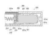
도 5는 본 발명의 제 2 실시예에 따른 기화 흡입 장치의 제 2 분할 부재의 구성을 보이는 단면도이고, 도 6은 본 발명의 제 2 실시예에 따른 기화 흡입 장치의 제 2 분할 부재에서 기화 대상체가 감소되었을 때의 모습을 보이는 단면도이다.5 is a cross-sectional view showing a configuration of a second partition member of the vaporization suction device according to a second embodiment of the present invention, Figure 6 is a vaporization object in the second partition member of the vaporization suction device according to a second embodiment of the present invention Is a cross-sectional view of the state when is reduced.
도 5 및 도 6을 함께 참조하면, 본 실시예에서는, 기화 대상체 수용 부재(260)의 수용 부재 몸체(261)가 고무 재질 등 탄성을 가진 물질로 이루어진다. 그러면, 상기 수용 부재 몸체(261) 내부에 수용된 기화 대상체(261)가 액화되어 상기 수용 부재 몸체(261)에서 이탈되면, 도 6에 도시된 바와 같이, 상기 수용 부재 몸체(261)가 자체적인 탄성에 의해 축소될 수 있다. 따라서, 상기 기화 대상체(262)가 상기 수용 부재 몸체(261)의 탄성에 의해 액화 부재(265) 쪽으로 밀리게 되므로, 상기 액화 부재(265)에 의한 상기 기화 대상체(262)의 액화가 원활하게 이루어질 수 있다.5 and 6 together, in the present embodiment, the receiving
상기 수용 부재 몸체(261)를 구성하는 재질은 고무 재질 외에도 변형 가능한 다양한 재질이 제시될 수 있다.The material constituting the receiving
상기에서 본 발명은 특정한 실시예에 관하여 도시되고 설명되었지만, 당업계에서 통상의 지식을 가진 자라면 이하의 특허청구범위에 기재된 본 발명의 사상 및 영역을 벗어나지 않는 범위 내에서 본 발명을 다양하게 수정 및 변경시킬 수 있음을 알 수 있을 것이다. 그렇지만 이러한 수정 및 변형 구조들은 모두 본 발명의 권리범위 내에 포함되는 것임을 분명하게 밝혀두고자 한다.While the invention has been shown and described with respect to specific embodiments thereof, those skilled in the art can variously modify the invention without departing from the spirit and scope of the invention as set forth in the claims below. And that it can be changed. However, it is intended that the present invention covers the modifications and variations of this invention provided they come within the scope of the appended claims and their equivalents.
본 발명의 일 측면에 따른 기화 흡입 장치에 의하면, 고체 형태의 기화 대상체를 기화시킬 수 있으므로, 그 산업상 이용 가능성이 높다고 하겠다.
According to the vaporization suction device according to an aspect of the present invention, since it is possible to vaporize the vaporized object in the solid form, it is said that the industrial applicability is high.
Claims (4)
Translated fromKorean고체 형태의 상기 기화 대상체를 수용하는 기화 대상체 수용 부재; 및
상기 기화 대상체 수용 부재에 수용된 고체 형태의 상기 기화 대상체를 액화 및 기화시키는 액화 기화 부재;를 포함하고,
상기 액화 기화 부재는
상기 기화 대상체 수용 부재에 수용된 고체 형태의 상기 기화 대상체를 액화시키는 액화 부재와, 상기 액화 부재에 의해 액화된 상기 기화 대상체를 기화시키는 기화 부재로 구성되고,
상기 수용 부재에 수용된 고체 형태의 상기 기화 대상체는 상기 액화 부재와 상기 기화 부재를 경유하면서, 순차적으로 액화 및 기화되는 것을 특징으로 하는 기화 흡입 장치.A vaporization suction device capable of vaporizing a vaporization object accommodated therein for inhalation by a user to inhalation gas,
A vaporized object receiving member for receiving the vaporized object in solid form; And
And a liquefied vaporization member configured to liquefy and vaporize the vaporized object in a solid form accommodated in the vaporized object receiving member.
The liquefied vaporization member
A liquefaction member for liquefying the vaporized object in solid form accommodated in the vaporization object receiving member, and a vaporization member for vaporizing the vaporized object liquefied by the liquefied member,
The vaporization object of the solid form accommodated in the receiving member is liquefied and vaporized sequentially while passing through the liquefaction member and the vaporization member, vaporization suction device.
상기 기화 대상체 수용 부재는
상기 기화 대상체가 내부에 수용되는 수용 부재 몸체와,
상기 액화 부재 쪽으로 상기 기화 대상체를 밀어주는 푸싱 부재와,
상기 푸싱 부재가 상기 액화 부재 쪽으로 밀리도록 탄성을 가하는 탄성 부재를 포함하는 것을 특징으로 하는 기화 흡입 장치.The method of claim 1,
The vaporization object receiving member is
An accommodation member body in which the vaporization object is received;
A pushing member for pushing the vaporization object toward the liquefaction member;
And an elastic member for applying elasticity to push the pushing member toward the liquefied member.
상기 기화 대상체 수용 부재는 상기 액화 부재 쪽으로 상기 기화 대상체가 밀리도록 탄성을 가진 물질로 이루어진 것을 특징으로 하는 기화 흡입 장치.
The method of claim 1,
And the vaporizing object receiving member is made of an elastic material such that the vaporizing object is pushed toward the liquefied member.
Priority Applications (1)
| Application Number | Priority Date | Filing Date | Title |
|---|---|---|---|
| KR1020110053564AKR101193644B1 (en) | 2011-06-02 | 2011-06-02 | Vaporizing and inhaling apparatus |
Applications Claiming Priority (1)
| Application Number | Priority Date | Filing Date | Title |
|---|---|---|---|
| KR1020110053564AKR101193644B1 (en) | 2011-06-02 | 2011-06-02 | Vaporizing and inhaling apparatus |
Related Parent Applications (1)
| Application Number | Title | Priority Date | Filing Date |
|---|---|---|---|
| KR2020090013128UDivisionKR20110003709U (en) | 2009-10-08 | 2009-10-08 | Vaporizing and inhaling apparatus |
Publications (2)
| Publication Number | Publication Date |
|---|---|
| KR20110084388A KR20110084388A (en) | 2011-07-22 |
| KR101193644B1true KR101193644B1 (en) | 2012-10-24 |
Family
ID=44921579
Family Applications (1)
| Application Number | Title | Priority Date | Filing Date |
|---|---|---|---|
| KR1020110053564AExpired - Fee RelatedKR101193644B1 (en) | 2011-06-02 | 2011-06-02 | Vaporizing and inhaling apparatus |
Country Status (1)
| Country | Link |
|---|---|
| KR (1) | KR101193644B1 (en) |
Cited By (4)
| Publication number | Priority date | Publication date | Assignee | Title |
|---|---|---|---|---|
| EP3504991B1 (en) | 2013-12-23 | 2021-01-27 | Juul Labs International Inc. | Vaporization device systems |
| US11992044B2 (en) | 2013-12-23 | 2024-05-28 | Juul Labs, Inc. | Vaporization device systems and methods |
| US12063973B2 (en) | 2016-02-25 | 2024-08-20 | Juul Labs, Inc. | Vaporization device control systems and methods |
| US12279646B2 (en) | 2014-02-06 | 2025-04-22 | Juul Labs, Inc. | Cartridge of vaporization device systems having unequal transverse cartridge dimensions |
Families Citing this family (3)
| Publication number | Priority date | Publication date | Assignee | Title |
|---|---|---|---|---|
| KR101186229B1 (en)* | 2011-12-13 | 2012-09-27 | 주식회사 기하정밀 | Electornic cigar |
| US10226073B2 (en)* | 2015-06-09 | 2019-03-12 | Rai Strategic Holdings, Inc. | Electronic smoking article including a heating apparatus implementing a solid aerosol generating source, and associated apparatus and method |
| KR102142635B1 (en)* | 2018-03-06 | 2020-08-07 | 주식회사 케이티앤지 | Method and device for supplying power |
- 2011
- 2011-06-02KRKR1020110053564Apatent/KR101193644B1/ennot_activeExpired - Fee Related
Cited By (5)
| Publication number | Priority date | Publication date | Assignee | Title |
|---|---|---|---|---|
| EP3504991B1 (en) | 2013-12-23 | 2021-01-27 | Juul Labs International Inc. | Vaporization device systems |
| US11752283B2 (en) | 2013-12-23 | 2023-09-12 | Juul Labs, Inc. | Vaporization device systems and methods |
| US11992044B2 (en) | 2013-12-23 | 2024-05-28 | Juul Labs, Inc. | Vaporization device systems and methods |
| US12279646B2 (en) | 2014-02-06 | 2025-04-22 | Juul Labs, Inc. | Cartridge of vaporization device systems having unequal transverse cartridge dimensions |
| US12063973B2 (en) | 2016-02-25 | 2024-08-20 | Juul Labs, Inc. | Vaporization device control systems and methods |
Also Published As
| Publication number | Publication date |
|---|---|
| KR20110084388A (en) | 2011-07-22 |
Similar Documents
| Publication | Publication Date | Title |
|---|---|---|
| KR101193644B1 (en) | Vaporizing and inhaling apparatus | |
| KR101165772B1 (en) | Liquid vaporizing and inhaling apparatus | |
| KR101233985B1 (en) | Electronic cigarette Liquid vaporizing and inhaling type | |
| KR101162688B1 (en) | Vaporizing and inhaling apparatus | |
| KR20120104964A (en) | Electronic cigarette liquid vaporizing and inhaling type | |
| KR20100006995U (en) | Liquid vaporizing and inhaling apparatus | |
| KR20200005159A (en) | Cigarette type electronic cigarette | |
| KR101184082B1 (en) | Vaporizing and inhaling apparatus | |
| KR20120025569A (en) | Vaporizing and inhaling apparatus | |
| KR101269244B1 (en) | Vaporizing and inhaling apparatus | |
| KR20110003309U (en) | Vaporizing and inhaling apparatus | |
| KR101165778B1 (en) | Liquid vaporizing and inhaling apparatus | |
| CN113056213B (en) | Smoking tools | |
| KR20100011034U (en) | Liquid vaporizing and inhaling apparatus | |
| KR20090003871U (en) | Liquid vaporization suction device | |
| KR101269246B1 (en) | Vaporizing and inhaling apparatus | |
| KR20110079587A (en) | Liquid vaporization suction device including cloud protection | |
| KR20110003709U (en) | Vaporizing and inhaling apparatus | |
| KR200467156Y1 (en) | Liquid vaporization suction device | |
| KR200479089Y1 (en) | Bundle type e-cigarette, case for bundle type e-cigarette and bundle type inhaling member for e-cigarette | |
| KR101269245B1 (en) | Vaporizing and inhaling apparatus | |
| KR20150003311U (en) | Bundle type e-cigarette, case for bundle type e-cigarette and bundle type inhaling member for e-cigarette | |
| KR200455132Y1 (en) | Liquid vaporization suction device | |
| KR101162683B1 (en) | Liquid vaporizing and inhaling apparatus | |
| KR20100012095U (en) | Liquid vaporizing and inhaling apparatus comprising rolling preventing portion |
Legal Events
| Date | Code | Title | Description |
|---|---|---|---|
| A201 | Request for examination | ||
| PA0106 | Converted application | St.27 status event code:A-0-1-A10-A19-cnv-PA0106 St.27 status event code:A-0-1-A10-A21-cnv-PA0106 | |
| PA0201 | Request for examination | St.27 status event code:A-1-2-D10-D11-exm-PA0201 | |
| PG1501 | Laying open of application | St.27 status event code:A-1-1-Q10-Q12-nap-PG1501 | |
| D13-X000 | Search requested | St.27 status event code:A-1-2-D10-D13-srh-X000 | |
| D14-X000 | Search report completed | St.27 status event code:A-1-2-D10-D14-srh-X000 | |
| E902 | Notification of reason for refusal | ||
| PE0902 | Notice of grounds for rejection | St.27 status event code:A-1-2-D10-D21-exm-PE0902 | |
| T11-X000 | Administrative time limit extension requested | St.27 status event code:U-3-3-T10-T11-oth-X000 | |
| E13-X000 | Pre-grant limitation requested | St.27 status event code:A-2-3-E10-E13-lim-X000 | |
| P11-X000 | Amendment of application requested | St.27 status event code:A-2-2-P10-P11-nap-X000 | |
| P13-X000 | Application amended | St.27 status event code:A-2-2-P10-P13-nap-X000 | |
| R18-X000 | Changes to party contact information recorded | St.27 status event code:A-3-3-R10-R18-oth-X000 | |
| E701 | Decision to grant or registration of patent right | ||
| PE0701 | Decision of registration | St.27 status event code:A-1-2-D10-D22-exm-PE0701 | |
| GRNT | Written decision to grant | ||
| PR0701 | Registration of establishment | St.27 status event code:A-2-4-F10-F11-exm-PR0701 | |
| PR1002 | Payment of registration fee | Fee payment year number:1 St.27 status event code:A-2-2-U10-U11-oth-PR1002 | |
| PG1601 | Publication of registration | St.27 status event code:A-4-4-Q10-Q13-nap-PG1601 | |
| PN2301 | Change of applicant | St.27 status event code:A-5-5-R10-R11-asn-PN2301 St.27 status event code:A-5-5-R10-R13-asn-PN2301 | |
| R18-X000 | Changes to party contact information recorded | St.27 status event code:A-5-5-R10-R18-oth-X000 | |
| R18-X000 | Changes to party contact information recorded | St.27 status event code:A-5-5-R10-R18-oth-X000 | |
| FPAY | Annual fee payment | Payment date:20150819 Year of fee payment:4 | |
| PR1001 | Payment of annual fee | Fee payment year number:4 St.27 status event code:A-4-4-U10-U11-oth-PR1001 | |
| P22-X000 | Classification modified | St.27 status event code:A-4-4-P10-P22-nap-X000 | |
| FPAY | Annual fee payment | Payment date:20170328 Year of fee payment:5 | |
| PR1001 | Payment of annual fee | Fee payment year number:5 St.27 status event code:A-4-4-U10-U11-oth-PR1001 | |
| FPAY | Annual fee payment | Payment date:20170927 Year of fee payment:6 | |
| PR1001 | Payment of annual fee | Fee payment year number:6 St.27 status event code:A-4-4-U10-U11-oth-PR1001 | |
| FPAY | Annual fee payment | Payment date:20180912 Year of fee payment:7 | |
| PR1001 | Payment of annual fee | Fee payment year number:7 St.27 status event code:A-4-4-U10-U11-oth-PR1001 | |
| P22-X000 | Classification modified | St.27 status event code:A-4-4-P10-P22-nap-X000 | |
| PC1903 | Unpaid annual fee | Not in force date:20191017 Payment event data comment text:Termination Category : DEFAULT_OF_REGISTRATION_FEE St.27 status event code:A-4-4-U10-U13-oth-PC1903 | |
| PC1903 | Unpaid annual fee | Ip right cessation event data comment text:Termination Category : DEFAULT_OF_REGISTRATION_FEE Not in force date:20191017 St.27 status event code:N-4-6-H10-H13-oth-PC1903 | |
| P22-X000 | Classification modified | St.27 status event code:A-4-4-P10-P22-nap-X000 |