KR101193002B1 - Cleaning appliance and control circuitry - Google Patents
Cleaning appliance and control circuitryDownload PDFInfo
- Publication number
- KR101193002B1 KR101193002B1KR1020077018882AKR20077018882AKR101193002B1KR 101193002 B1KR101193002 B1KR 101193002B1KR 1020077018882 AKR1020077018882 AKR 1020077018882AKR 20077018882 AKR20077018882 AKR 20077018882AKR 101193002 B1KR101193002 B1KR 101193002B1
- Authority
- KR
- South Korea
- Prior art keywords
- motor
- stirrer
- cleaner
- dust
- main motor
- Prior art date
- Legal status (The legal status is an assumption and is not a legal conclusion. Google has not performed a legal analysis and makes no representation as to the accuracy of the status listed.)
- Expired - Fee Related
Links
Images

Classifications
- A—HUMAN NECESSITIES
- A47—FURNITURE; DOMESTIC ARTICLES OR APPLIANCES; COFFEE MILLS; SPICE MILLS; SUCTION CLEANERS IN GENERAL
- A47L—DOMESTIC WASHING OR CLEANING; SUCTION CLEANERS IN GENERAL
- A47L9/00—Details or accessories of suction cleaners, e.g. mechanical means for controlling the suction or for effecting pulsating action; Storing devices specially adapted to suction cleaners or parts thereof; Carrying-vehicles specially adapted for suction cleaners
- A47L9/02—Nozzles
- A47L9/04—Nozzles with driven brushes or agitators
- A47L9/0405—Driving means for the brushes or agitators
- A47L9/0411—Driving means for the brushes or agitators driven by electric motor
- A—HUMAN NECESSITIES
- A47—FURNITURE; DOMESTIC ARTICLES OR APPLIANCES; COFFEE MILLS; SPICE MILLS; SUCTION CLEANERS IN GENERAL
- A47L—DOMESTIC WASHING OR CLEANING; SUCTION CLEANERS IN GENERAL
- A47L5/00—Structural features of suction cleaners
- A47L5/12—Structural features of suction cleaners with power-driven air-pumps or air-compressors, e.g. driven by motor vehicle engine vacuum
- A47L5/22—Structural features of suction cleaners with power-driven air-pumps or air-compressors, e.g. driven by motor vehicle engine vacuum with rotary fans
- A47L5/28—Suction cleaners with handles and nozzles fixed on the casings, e.g. wheeled suction cleaners with steering handle
- A47L5/30—Suction cleaners with handles and nozzles fixed on the casings, e.g. wheeled suction cleaners with steering handle with driven dust-loosening tools, e.g. rotating brushes
- A—HUMAN NECESSITIES
- A47—FURNITURE; DOMESTIC ARTICLES OR APPLIANCES; COFFEE MILLS; SPICE MILLS; SUCTION CLEANERS IN GENERAL
- A47L—DOMESTIC WASHING OR CLEANING; SUCTION CLEANERS IN GENERAL
- A47L9/00—Details or accessories of suction cleaners, e.g. mechanical means for controlling the suction or for effecting pulsating action; Storing devices specially adapted to suction cleaners or parts thereof; Carrying-vehicles specially adapted for suction cleaners
- A47L9/02—Nozzles
- A47L9/04—Nozzles with driven brushes or agitators
- A—HUMAN NECESSITIES
- A47—FURNITURE; DOMESTIC ARTICLES OR APPLIANCES; COFFEE MILLS; SPICE MILLS; SUCTION CLEANERS IN GENERAL
- A47L—DOMESTIC WASHING OR CLEANING; SUCTION CLEANERS IN GENERAL
- A47L9/00—Details or accessories of suction cleaners, e.g. mechanical means for controlling the suction or for effecting pulsating action; Storing devices specially adapted to suction cleaners or parts thereof; Carrying-vehicles specially adapted for suction cleaners
- A47L9/28—Installation of the electric equipment, e.g. adaptation or attachment to the suction cleaner; Controlling suction cleaners by electric means
- A47L9/2836—Installation of the electric equipment, e.g. adaptation or attachment to the suction cleaner; Controlling suction cleaners by electric means characterised by the parts which are controlled
- A47L9/2842—Suction motors or blowers
- A—HUMAN NECESSITIES
- A47—FURNITURE; DOMESTIC ARTICLES OR APPLIANCES; COFFEE MILLS; SPICE MILLS; SUCTION CLEANERS IN GENERAL
- A47L—DOMESTIC WASHING OR CLEANING; SUCTION CLEANERS IN GENERAL
- A47L9/00—Details or accessories of suction cleaners, e.g. mechanical means for controlling the suction or for effecting pulsating action; Storing devices specially adapted to suction cleaners or parts thereof; Carrying-vehicles specially adapted for suction cleaners
- A47L9/28—Installation of the electric equipment, e.g. adaptation or attachment to the suction cleaner; Controlling suction cleaners by electric means
- A47L9/2836—Installation of the electric equipment, e.g. adaptation or attachment to the suction cleaner; Controlling suction cleaners by electric means characterised by the parts which are controlled
- A47L9/2847—Surface treating elements
- A—HUMAN NECESSITIES
- A47—FURNITURE; DOMESTIC ARTICLES OR APPLIANCES; COFFEE MILLS; SPICE MILLS; SUCTION CLEANERS IN GENERAL
- A47L—DOMESTIC WASHING OR CLEANING; SUCTION CLEANERS IN GENERAL
- A47L9/00—Details or accessories of suction cleaners, e.g. mechanical means for controlling the suction or for effecting pulsating action; Storing devices specially adapted to suction cleaners or parts thereof; Carrying-vehicles specially adapted for suction cleaners
- A47L9/28—Installation of the electric equipment, e.g. adaptation or attachment to the suction cleaner; Controlling suction cleaners by electric means
- A47L9/2857—User input or output elements for control, e.g. buttons, switches or displays
- A—HUMAN NECESSITIES
- A47—FURNITURE; DOMESTIC ARTICLES OR APPLIANCES; COFFEE MILLS; SPICE MILLS; SUCTION CLEANERS IN GENERAL
- A47L—DOMESTIC WASHING OR CLEANING; SUCTION CLEANERS IN GENERAL
- A47L9/00—Details or accessories of suction cleaners, e.g. mechanical means for controlling the suction or for effecting pulsating action; Storing devices specially adapted to suction cleaners or parts thereof; Carrying-vehicles specially adapted for suction cleaners
- A47L9/28—Installation of the electric equipment, e.g. adaptation or attachment to the suction cleaner; Controlling suction cleaners by electric means
- A47L9/2894—Details related to signal transmission in suction cleaners
- Y—GENERAL TAGGING OF NEW TECHNOLOGICAL DEVELOPMENTS; GENERAL TAGGING OF CROSS-SECTIONAL TECHNOLOGIES SPANNING OVER SEVERAL SECTIONS OF THE IPC; TECHNICAL SUBJECTS COVERED BY FORMER USPC CROSS-REFERENCE ART COLLECTIONS [XRACs] AND DIGESTS
- Y10—TECHNICAL SUBJECTS COVERED BY FORMER USPC
- Y10S—TECHNICAL SUBJECTS COVERED BY FORMER USPC CROSS-REFERENCE ART COLLECTIONS [XRACs] AND DIGESTS
- Y10S15/00—Brushing, scrubbing, and general cleaning
- Y10S15/10—Handles, reels and switches
Landscapes
- Engineering & Computer Science (AREA)
- Mechanical Engineering (AREA)
- Nozzles For Electric Vacuum Cleaners (AREA)
- Electric Vacuum Cleaner (AREA)
Abstract
Translated fromKoreanDescription
Translated fromKorean본 발명은 진공 청소기와 같은, 청소 기구용 클리너 헤드에 관한 것이다.The present invention relates to a cleaner head for a cleaning appliance, such as a vacuum cleaner.
대부분의 진공 청소기는 일부의 국가에서 캐니스터(canister) 청소기 또는 배럴(barrel) 청소기라 하는, '직립'형 또는 '실린더'형이다. 직립 진공 청소기는 통상적으로 먼지 및 티끌 분리 장치를 포함하는 메인 바디, 상기 메인 바디 위에 회전 가능하게 장착되어 있고 더러운 공기 입구(dirty air inlet)를 가진 클리너 헤드, 및 상기 더러운 공기 입구를 통해 상기 먼지 및 티끌 분리 장치로 더러운 공기를 빨아들이고 먼지 및 티끌을 공기흐름으로부터 분리시켜 깨끗한 공기를 대기중으로 배출시키는 모터 및 팬 유닛을 포함한다. 진공 청소기에 더러운 공기를 빨아들이는 상기 더러운 공기 입구는 청소할 마루와 마주하도록 아래로 향하게 되어 있다. 상기 먼지 및 티끌 분리 장치는 필터 백(filter bag)의 형태일 수도 있고, 사이클로닉 장치(cyclonic arrangement)의 형태일 수도 있다. 본 발명은 먼지 및 티끌 분리 장치의 특성에 관한 것이 아니므로 어느 한 쪽의 장치를 사용하는 진공 청소기에 적용될 수 있다.Most vacuum cleaners are 'upright' or 'cylinder' type, in some countries called canister cleaners or barrel cleaners. An upright vacuum cleaner typically includes a main body comprising a dust and dust separation device, a cleaner head rotatably mounted on the main body and having a dirty air inlet, and the dust and dirt through the dirty air inlet. It includes a motor and fan unit that sucks in dirty air with a dust separation device and separates dust and dust from the airflow and discharges clean air into the atmosphere. The dirty air inlet, which sucks dirty air into the vacuum cleaner, is faced down to face the floor to be cleaned. The dust and dust separation device may be in the form of a filter bag or in the form of a cyclonic arrangement. The present invention does not relate to the characteristics of the dust and dust separating apparatus and therefore can be applied to a vacuum cleaner using either apparatus.
예를 들어 브러시 바 형태의 교반기는 상기 더러운 공기 입구로부터 약간 튀어나와서 상기 더러운 공기 입구에서 지지된다. 상기 브러시 바는 통상적으로 그 길이를 따라 방사상으로 연장된 긴 원통형 코어(elongate cylindrical core)를 포함한다. 상기 브러시 바는 통상적으로 구동 벨트를 통해 모터에 의해 구동되어 상기 더러운 공기 입구 내에서 회전한다. 상기 브러시 바가 회전함에 따라 솔(bristles)이 청소할 카페트의 섬유로부터 먼지와 부스러기를 털어낸다. 공기의 흡입에 의해 브러시 바 주위와 브러시 바 아래에서 공기가 흐르게 되어 청소할 표면으로부터 먼지 및 티끌이 들어올려진 다음 더러운 공기 입구로부터 먼지 및 티끌 분리 장치로 운반된다. 카페트가 깔린 표면을 청소할 때 교반기를 사용하면 사용하지 않을 때보다 청소가 더 깨끗하게 된다.A stirrer, for example in the form of a brush bar, sticks slightly out of the dirty air inlet and is supported at the dirty air inlet. The brush bar typically comprises an elongate cylindrical core extending radially along its length. The brush bar is typically driven by a motor through a drive belt to rotate within the dirty air inlet. As the brush bar rotates, the brushes shake off dirt and debris from the fibers of the carpet to be cleaned. Inhalation of air causes air to flow around the brush bar and under the brush bar, picking up dust and dirt from the surface to be cleaned and then transporting it from the dirty air inlet to the dust and dust separator. If you use a stirrer to clean carpeted surfaces, the cleaning will be cleaner than when not in use.
본 발명의 제1 실시예에서는 청소 기구용 클리너 헤드가 제공되며, 상기 청소 기구는 먼지 및 티끌 분리 수단, 흡입 공기 흐름(suction air flow)을 발생하는 팬을 구동하도록 배치된 모터, 및 상기 모터를 구동하기 위한 선택적으로 작동 가능한 스위치(selectively-operable switch)를 포함하며, 상기 클리너 헤드는, 사용자가 상기 모터를 스위치 온 하였을 때 자동으로 구동되도록 배치된 구동 가능한 교반기(driveable agitator)를 포함한다.In a first embodiment of the invention there is provided a cleaner head for a cleaning appliance, the cleaning appliance comprising a motor arranged to drive dust and dirt separating means, a fan generating suction air flow, and the motor. And a selectively-operable switch for driving, wherein the cleaner head includes a driveable agitator arranged to be automatically driven when the user switches on the motor.
본 발명의 제2 실시예에서는, 먼지 및 티끌 분리 수단; 흡입 공기 흐름을 발생하는 팬을 구동하도록 배치된 모터; 상기 모터를 구동하기 위한 선택적으로 작동 가능한 스위치; 및 사용자가 상기 모터를 스위치 온 하였을 때 자동으로 구동되도록 배치된 구동 가능한 교반기를 갖는 클리너 헤드가 내장된 메인 바디를 포함하는 청소 기구가 제공된다.In a second embodiment of the present invention, there is provided a dust and dust separating means; A motor arranged to drive a fan generating intake air flow; A selectively operable switch for driving the motor; And a main body with a built-in cleaner head having a driveable agitator arranged to be automatically driven when the user switches on the motor.
본 발명의 다른 실시예에서는 청소 기구용 제어 회로가 제공되며, 상기 청소 기구는, 먼지 및 티끌 분리 수단, 흡입 공기 흐름을 발생하는 팬을 구동하도록 배치된 모터, 및 구동 가능한 교반기를 갖는 클리너 헤드를 포함하며, 상기 제어 회로는, 상기 모터를 구동하기 위한 선택적으로 작동 가능한 스위치를 포함하고, 사용자가 상기 모터가 스위치 온 하였을 때 상기 구동 가능한 교반기가 자동으로 구동된다.In another embodiment of the present invention there is provided a control circuit for a cleaning appliance, said cleaning appliance comprising a cleaner head having dust and dust separating means, a motor arranged to drive a fan generating intake air flow, and a stirrer capable of driving. And the control circuit includes a selectively operable switch for driving the motor, wherein the driveable agitator is automatically driven when the user switches on the motor.
종래의 청소기에서는 사용자가 청소기를 사용할 때 교반기를 사용하는 것을 잊어버려 청소를 최적으로 하지 못하는 경향이 있다는 것이 밝혀졌다. 본 발명에서는 메인 진공 모터가 작동하기 시작할 때 교반기가 자동으로 구동되도록 함으로써 이런 일이 생기는 것을 방지한다.It has been found in conventional cleaners that a user tends to forget to use an agitator when using the cleaner and thus does not optimally clean. The present invention prevents this from happening by having the stirrer run automatically when the main vacuum motor starts to operate.
양호하게, 상기 교반기는 클리너 헤드에 설치될 수 있는 그 자체의 전용 모터에 의해 구동된다.Preferably, the stirrer is driven by its own dedicated motor which can be installed in the cleaner head.
교반기 모터용 스위치를 설치하여, 사용자가 카페트가 깔리지 않은 표면을 청소하고자 할 때는 상기 교반기 모터를 구동하지 않을 수 있다. 계속해서 카페트가 깔린 표면을 청소할 때는 상기 교반기 모터를 재구동할 수 있다,By installing a switch for the stirrer motor, the user may not drive the stirrer motor when the user wants to clean the uncarpeted surface. When the carpeted surface is subsequently cleaned, the stirrer motor can be restarted.
본 발명에 대해 첨부된 도면을 참조하여 예를 들어 설명한다.With reference to the accompanying drawings, the present invention will be described by way of example.
도 1은 본 발명의 제1 실시예에 따라 구성된 표면 청소 기구의 정면도이다.1 is a front view of a surface cleaning mechanism constructed in accordance with a first embodiment of the present invention.
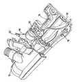
도 2는 도 1의 표면 청소 기구의 표면 청소 헤드를 부분적으로 절단하여 도시한 사시도이다.FIG. 2 is a perspective view partially cut of the surface cleaning head of the surface cleaning mechanism of FIG. 1. FIG.
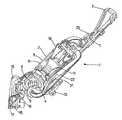
도 3은 사용 모드 시에서의 도 1의 표면 청소 기구를 부분적으로 절단하여 도시한 사시도이다.3 is a perspective view partially cut away and showing the surface cleaning mechanism of FIG. 1 in the use mode.
상세한 설명에서 동일한 도면 부호는 동일한 부분을 나타낸다.Like reference symbols in the detailed description indicate like parts.
도 1 및 도 3을 참조하면, 표면 청소 기구는 진공 청소기의 형태로 도시되어 있고 일반적으로 도면 부호 1로 표시되어 있다. 진공 청소기(1)는 메인 바디(main body)(2), 사용자 동작 가능 핸들(user-operable hanle)(3) 및 마루 표면을 따라 청소기를 굴러가게 하는 대형 롤러(4)를 포함한다.1 and 3, the surface cleaning device is shown in the form of a vacuum cleaner and is generally indicated with reference 1. The vacuum cleaner 1 comprises a
도 3에서 볼 수 있는 바와 같이, 상기 대형 롤러(4)는 팬(5)과 상기 팬을 구동하는 모터(6)를 내장하고 있다. 상기 모터(6)와 상기 팬(5)은 공기와 같은 유체(fluid)를 장치 안으로 빨아들이기 위한 흡입(suction)을 생성한다. 상기 모터(6)와 상기 팬(5)은 상기 대형 롤러(4)와 함께 회전하도록 배치되어 있거나, 상기 대형 롤러(4)가 상기 모터(6)와 상기 팬(5)에 대해 회전하도록 되어 있다. 상기 메인 바디(2)의 상부 위에 사용자 동작 가능 버튼(7)이 설치되어, 상기 사용자 동작 가능 버튼(7)을 누르면 상기 모터(6)가 구동된다. 상기 모터 역시 상기 사용자 동작 가능 버튼(7)에 의해 구동되지 않을 수 있다.As can be seen in FIG. 3, the
상기 메인 바디(2)는 또한 상기 팬(5)과 상기 모터(6)에 의해 상기 청소기 안으로 빨아들이는 더러운 공기흐름으로부터 먼지, 티끌 및 그외 부스러기를 분리하는 분리 장치(8)를 내장한다. 본 실시예에서, 상기 분리 장치(8)는 상기 더러운 공기흐름으로부터 먼지 및 티끌을 회전시키는 사이클로닉이다. 상기 사이클로닉 분리 장치(8)는 서로 직렬로 배열된 2단의 사이클론 분리로 이루어져 있다. 제1 단은 원통형 벽의 챔버(cylindrically-walled chamber)(9)이고, 제2 단은 서로 평행하게 배열된 테이퍼식의, 실질적으로 원추대 형상의 챔버(frusto-conically shaped chambers) 세트(10)로 이루어져 있다. 공기흐름은 제1 사이클로닉 챔버(9)의 상부쪽으로 접하게(tangentially) 향하도록 되어 있다. 큰 부스러기 및 작은 조각은 제1 사이클로닉 챔버(9)로 옮겨져서 집진된다. 이때 공기 흐름이 덮개(11)를 통과하여 소형의 원추대 형상의 챔버 세트(10)로 향한다. 미세 먼지는 이러한 챔버들에 의해 분리되고 분리된 먼지는 공통 집진 영역에 집진된다. 제2 분리기 세트(10)는 직립형이 될 수 있는데, 즉 유체 입구 및 유체 출구를 상부에 그리고 쓰레기 출구(dirt outlet)를 하부에 설치하거나, 반대로 유체 입구 및 유체 출구를 하부에 그리고 쓰레기 출구를 상부에 설치한다. 먼지 분리 장치(8)의 특성은 본 발명에 관한 것이 아니다.The
메인 바디(2) 역시 정화된 공기흐름 속에서 미세 입자를 걸러내기 위한 필터들(도면에서는 보이지 않음)을 내장한다. 이들 필터는 상기 먼지 분리 장치에 의해 공기흐름에서 이미 제거되지 않은 어떠한 미세 먼지 입자라도 제거한다. 프리-모터 필터(pre-motor filter)라 하는 제1 필터를 모터(6) 및 팬(5) 앞에 설치한다. 포스트-모터 필터(post-motor filter)라 하는 제2 필터를 모터(6) 및 팬(5) 뒤에 설치한다. 흡입 팬(5)을 구동하는 모터(6)에 카본 브러시(carbon brushes)가 있는 경우, 포스트-모터 필터 역시 상기 카본 브러시에 의해 방출된 카본 입자를 걸러내는 기능을 한다. 그런 다음 깨끗한 공기가 대기중으로 배출된다.The
대형 롤러(4)에 의해 청소기는 마루 표면을 따라 쉽게 기동할 수 있다. 그 렇지만, 메인 바디(2)가 수직으로 있을 때나 실질적으로 수직 위치에 있을 때에는, 상기 대형 롤러(4)는 청소기를 충분히 지지하지 못한다. 이 목적을 위해, 지지 어셈블리(12)를 설치한다.The
사용자 동작 가능 핸들(3)은 메인 바디(2)의 뒷부분으로부터 위로 연장한다. 청소기가 도 1에 도시된 바와 같은 위치로 되어 있을 때, 사용자 동작 가능 핸들을 실린더 모드에서 사용할 수 있는데, 이 경우 사용자 동작 가능 핸들(3)을 해제하여 호스 및 청소대 어셈블리(hose and wand assembly)로서 사용할 수도 있다. 메인 바디(2) 위의 전환 밸브(changeover valve)에 의해 상기 먼지 분리 장치(8)가 상기 호스 및 청소대 어셈블리에 자동으로 연결되어 마루 청소를 위한 이러한 실린더 모드에서 청소기를 사용할 수 있다. 적당한 조작으로 청소기로부터 해제할 수 있는 청소대의 단부를 통해 공기를 청소기로 빨아들인다.The user
청소기(1)를 종래의 직립 모드에서 사용할 때, 사용자는 메인 바디(2)를 기울인다. 도 3에 도시된 바와 같이, 직립으로 청소하기 위해 청소기(1)의 메인 바디(2)를 위해 기울일 때는 지지 어셈블리(2)를 접어 넣을 수 있도록 되어 있다.When using the vacuum cleaner 1 in the conventional upright mode, the user tilts the
클리너 헤드(13)는 직립 청소 모드에서 마루 표면을 청소하는 기능을 하며, 도 2에 상세히 도시되어 있다. 본 실시예에서, 클리너 헤드는 브러시 바(15) 형태의 교반기를 지지하는 챔버(14)를 포함한다. 상기 챔버(14)의 하부의 마루 대향 측에는 공기 입구 슬롯(16)이 있고 상기 브러시 바(15)는 상기 챔버 내에 회전 가능하게 장착되어 있어, 브리서 바 위의 솔(17)이 상기 공기 입구 슬롯을 통해 돌출하여 클리너 헤드가 지나가는 마루 표면을 휘저을 수 있도록 되어 있다. 상기 브 러시 바(15)는 상기 클리너 헤드 내측에 위치한 전용 모터(18)에 의해 회전 가능하게 구동된다. 기어 시스템(19)은 모터(18)를 브러시 바(15)에 연결하여 구동력을 제공한다.The
상기 브러시 바 모터(18)에 전기 접속(20)이 제공되어 상기 브러시 바 모터가 구동된다. 본 발명과 관련해서는, 메인 진공 모터(6)가 스위치 온 되었을 때, 상기 클리너 헤드 내의 상기 브러시 바 모터(18) 역시 구동하도록 배치되어 있으므로, 클리너가 가동하기 시작하면 상기 브러시 바(15)는 자동으로 구동된다.An
부분적으로 절단된 부분을 나타내는 도 3에는 청소를 시작할 때 브러시 바(15)의 구동이 자동으로 이루어지도록 적용될 수 있는 제어 회로(21)가 도시되어 있다. 상기 제어 회로(21)는 먼지 분리 장치(8)의 뒤 그리고 대형 롤러(4) 내에 위치한 메인 진공 모터(6)의 상류(upstream)에, 흡입 공기흐름 경로의 일부를 형성하는 덕트(22) 내에 위치한다. 공기흐름 내의 상기 제어 회로(21)의 위치 선정은 전자 부품이 적절하게 냉각될 수 있게 한다.3, which shows a partially cut away portion, is shown a
사용자는 또한 누름 버튼(23)의 형태로 청소기에 제공된 스위치에 의해 브러시 바 모터(18)의 구동 및 비구동을 선택할 수 있다. 상기 누름 버튼(23)은 종래부터 청소기의 메인 바디(2)의 상부에서 쉽게 눈에 띄이는 위치에 편리하게 설치되어 있다. 상기 누름 버튼(18)을 사용하여 브러시 바(15)용 모터(18)를 스위치 오프할 수 있다. 예를 들어, 사용자가 카페트가 깔리지 않은 표면을 청소하고자 할 때는 상기 브러시 바(15)를 사용할 필요가 없다. 대안으로, 사용자는 호스 및 청소대 어셈블리를 사용하여 청소할 수도 있다.The user can also select the drive and non-drive of the
본 실시예에서, 상기 누름 버튼(23)은 버튼(7)에 인접하여 제공되며, 상기 버튼(7)에 의해 사용자는 청소기(1)를 스위치 온하여, 흡입 공기흐름을 생성하는데 사용되는 메인 진공 모터(6)를 구동한다. 상기 버튼(7, 23) 위에는 그 버튼의 기능을 나타내는 시각적 표시(visual indicia)가 있다.In the present embodiment, the
제어 회로(21)는 그 자체가 리셋되도록 배치되어 있어서, 메인 진공 모터(6)가 스위치 오프되고 이어서 재구동될 때, 브러시 바 모터(18)가 자동으로 다시 가동을 시작하여 브러시 바(15)가 회전된다.The
본 발명을 직립 청소기를 참조하여 설명하였으나, 호스 및 청소대 어셈블리의 단부에 표면 청소 헤드가 설치된 실린더 청소기에도 적용 가능하다. 상기 클리너 헤드는 또한 어느 한 쪽 유형의 진공 청소기의 호스 및 청소대 어셈블리의 단부에 맞추어질 수 있는 마루 용구(floor tool)의 형태로 제공될 수도 있다.Although the present invention has been described with reference to an upright cleaner, it is also applicable to a cylinder cleaner provided with a surface cleaning head at the end of the hose and cleaning assembly. The cleaner head may also be provided in the form of a floor tool that can be fitted to the end of the hose and sweep assembly of either type of vacuum cleaner.
물론, 본 발명의 범주를 벗어남이 없이 다른 변형이 수행될 수도 있다. 예를 들어, 청소기의 메인 바디와 클리너 헤드 사이에 물리적 전기 접속이 없어도 된다. 전용 브러시 바 모터를 스위치 온하는데 무선 신호를 사용하며, 이 경우 브러시 바 모터는 배터리 팩(battery pack)과 같은 전용의 에너지원으로 편리하게 구동될 수 있다.Of course, other modifications may be made without departing from the scope of the present invention. For example, there may be no physical electrical connection between the main body of the cleaner and the cleaner head. Wireless signals are used to switch on a dedicated brush bar motor, in which case the brush bar motor can be conveniently driven by a dedicated energy source such as a battery pack.
기술한 실시예에서는 덕트가 공기흐름을 흐르게 하는 진공 청소기에 대해 설명하였으나, 본 발명은 물이나 세제와 같은 다른 유체가 흐르는 진공 청소기에도 적용될 수 있다는 것을 이해해야 한다.While the described embodiment has described a vacuum cleaner that allows air flow through the duct, it should be understood that the present invention can be applied to a vacuum cleaner through which other fluids, such as water or detergent, flow.
Claims (14)
Translated fromKoreanApplications Claiming Priority (3)
| Application Number | Priority Date | Filing Date | Title |
|---|---|---|---|
| GB0500990.7 | 2005-01-18 | ||
| GB0500990AGB2422093B (en) | 2005-01-18 | 2005-01-18 | Cleaner head for a cleaning appliance |
| PCT/GB2006/000061WO2006077377A1 (en) | 2005-01-18 | 2006-01-09 | Cleaner head for a cleaning appliance |
Publications (2)
| Publication Number | Publication Date |
|---|---|
| KR20070106725A KR20070106725A (en) | 2007-11-05 |
| KR101193002B1true KR101193002B1 (en) | 2012-10-19 |
Family
ID=34224768
Family Applications (1)
| Application Number | Title | Priority Date | Filing Date |
|---|---|---|---|
| KR1020077018882AExpired - Fee RelatedKR101193002B1 (en) | 2005-01-18 | 2006-01-09 | Cleaning appliance and control circuitry |
Country Status (12)
| Country | Link |
|---|---|
| US (1) | US7603745B2 (en) |
| EP (1) | EP1838194B1 (en) |
| JP (1) | JP4891263B2 (en) |
| KR (1) | KR101193002B1 (en) |
| CN (1) | CN101106930A (en) |
| AU (1) | AU2006207348B2 (en) |
| CA (1) | CA2594748C (en) |
| GB (1) | GB2422093B (en) |
| MY (1) | MY140526A (en) |
| RU (1) | RU2395224C2 (en) |
| TW (1) | TW200642652A (en) |
| WO (1) | WO2006077377A1 (en) |
Families Citing this family (18)
| Publication number | Priority date | Publication date | Assignee | Title |
|---|---|---|---|---|
| GB2440717A (en)* | 2006-08-08 | 2008-02-13 | Dyson Technology Ltd | Circuit breaker system for a vacuum cleaner |
| US20090193613A1 (en)* | 2008-02-04 | 2009-08-06 | Ruben Brian K | Dirt cup with secondary cyclonic cleaning chambers |
| US20100269289A1 (en)* | 2009-04-23 | 2010-10-28 | Ruben Brian K | Internal air separators in a dirt separation device |
| GB2470919A (en)* | 2009-06-09 | 2010-12-15 | Dyson Technology Ltd | Agitating means for a cleaning head |
| GB2470917A (en)* | 2009-06-09 | 2010-12-15 | Dyson Technology Ltd | Agitating means for cleaning head |
| GB2470918A (en)* | 2009-06-09 | 2010-12-15 | Dyson Technology Ltd | Agitating means for a cleaning head |
| GB2470920A (en)* | 2009-06-09 | 2010-12-15 | Dyson Technology Ltd | Agitating menas for a cleaning head |
| US8152877B2 (en)* | 2010-03-12 | 2012-04-10 | Euro-Pro Operating Llc | Shroud for a cleaning service apparatus |
| US8941659B1 (en) | 2011-01-28 | 2015-01-27 | Rescon Ltd | Medical symptoms tracking apparatus, methods and systems |
| EP2581014A1 (en)* | 2011-10-12 | 2013-04-17 | Black & Decker Inc. | A vaccum cleaner |
| GB2507320B (en)* | 2012-10-26 | 2014-12-10 | Dyson Technology Ltd | Switching mechanism |
| KR101768316B1 (en)* | 2015-07-29 | 2017-08-14 | 엘지전자 주식회사 | Vacuum cleaner and battery assembly |
| CN110049705A (en)* | 2016-10-14 | 2019-07-23 | 尚科宁家运营有限公司 | Vacuum cleaner with air agitation auxiliary |
| JP6506809B6 (en)* | 2017-09-28 | 2019-06-05 | 日立グローバルライフソリューションズ株式会社 | Electric vacuum cleaner |
| EP4009844A4 (en) | 2019-08-08 | 2023-09-06 | SharkNinja Operating LLC | CLEANING ROBOT WITH AIR NOZZLE ARRANGEMENT |
| EP4322812A4 (en) | 2021-04-12 | 2025-04-23 | SharkNinja Operating LLC | Robotic cleaner |
| US20240245190A1 (en) | 2023-01-19 | 2024-07-25 | Sharkninja Operating Llc | Identification of hair care appliance attachments |
| US20250213029A1 (en) | 2023-01-19 | 2025-07-03 | Sharkninja Operating Llc | Hair care appliance with powered attachment |
Family Cites Families (18)
| Publication number | Priority date | Publication date | Assignee | Title |
|---|---|---|---|---|
| GB456984A (en)* | 1935-05-18 | 1936-11-18 | Archibald Joseph Holt | Improvements in or relating to vacuum cleaners |
| US3588943A (en)* | 1968-11-12 | 1971-06-29 | Whirlpool Co | Vacuum cleaner suction and brush control |
| US4099291A (en)* | 1977-06-01 | 1978-07-11 | Bowerman Leonard E | Vacuum cleaner having magnetic drive for agitator brush |
| JPS5450156A (en)* | 1977-09-28 | 1979-04-19 | Hitachi Ltd | Upright electric cleaner |
| DE2902161A1 (en)* | 1979-01-20 | 1980-07-24 | Miele & Cie | Vacuum cleaner with pedal and manually operated pushbutton switch - has parallel circuit connection incorporated in control circuit of motor and relay which switches brushes (NL 22.7.80) |
| DE2947994A1 (en)* | 1979-11-28 | 1981-07-23 | Düpro AG, Romanshorn | ELECTRIC BRUSHES FOR VACUUM CLEANERS |
| DE3112376A1 (en)* | 1981-03-28 | 1982-11-18 | Miele & Cie GmbH & Co, 4830 Gütersloh | Vacuum cleaner, especially a floor vacuum cleaner |
| US4987637A (en) | 1986-10-20 | 1991-01-29 | Whirlpool Corporation | Canister vacuum cleaner and method of manufacture |
| JPH03186243A (en)* | 1989-12-15 | 1991-08-14 | Matsushita Electric Ind Co Ltd | Upright vacuum cleaner |
| JPH0497725A (en)* | 1990-08-14 | 1992-03-30 | Matsushita Electric Ind Co Ltd | Power nozzle driving device in storage battery type vacuum cleaner |
| JP2750976B2 (en)* | 1992-03-19 | 1998-05-18 | シャープ株式会社 | Electric vacuum cleaner |
| RU2152160C1 (en)* | 1998-01-06 | 2000-07-10 | Чепурина Наталья Николаевна | Vacuum cleaner control system |
| US6351872B1 (en)* | 1999-07-16 | 2002-03-05 | Matsushita Electric Corporation Of America | Agitator motor projection system for vacuum cleaner |
| US7159277B2 (en)* | 2001-02-06 | 2007-01-09 | The Hoover Company | Multiple chamber suction nozzle configuration |
| US20040134014A1 (en)* | 2003-01-10 | 2004-07-15 | Hawkins Thomas W. | Vacuum cleaner having a variable speed brushroll |
| FR2852811B1 (en)* | 2003-03-27 | 2005-06-24 | Nielsen Innovation | AUTONOMOUS BIMOTING VACUUM CLEANER |
| KR100504894B1 (en)* | 2003-05-07 | 2005-07-29 | 엘지전자 주식회사 | Brush of upright type vacuum cleaner |
| KR100531224B1 (en)* | 2003-06-09 | 2005-11-28 | 삼성광주전자 주식회사 | Turbine brush |
- 2005
- 2005-01-18GBGB0500990Apatent/GB2422093B/ennot_activeExpired - Lifetime
- 2006
- 2006-01-09KRKR1020077018882Apatent/KR101193002B1/ennot_activeExpired - Fee Related
- 2006-01-09USUS11/794,979patent/US7603745B2/enactiveActive
- 2006-01-09JPJP2007550832Apatent/JP4891263B2/ennot_activeExpired - Fee Related
- 2006-01-09WOPCT/GB2006/000061patent/WO2006077377A1/enactiveApplication Filing
- 2006-01-09RURU2007131285/12Apatent/RU2395224C2/ennot_activeIP Right Cessation
- 2006-01-09AUAU2006207348Apatent/AU2006207348B2/ennot_activeCeased
- 2006-01-09CNCNA2006800025746Apatent/CN101106930A/enactivePending
- 2006-01-09CACA2594748Apatent/CA2594748C/ennot_activeExpired - Fee Related
- 2006-01-09EPEP06700228.7Apatent/EP1838194B1/ennot_activeNot-in-force
- 2006-01-16MYMYPI20060176Apatent/MY140526A/enunknown
- 2006-01-17TWTW095101656Apatent/TW200642652A/enunknown
Also Published As
| Publication number | Publication date |
|---|---|
| US7603745B2 (en) | 2009-10-20 |
| EP1838194B1 (en) | 2014-12-24 |
| MY140526A (en) | 2009-12-31 |
| WO2006077377A1 (en) | 2006-07-27 |
| CA2594748C (en) | 2013-06-25 |
| CN101106930A (en) | 2008-01-16 |
| RU2007131285A (en) | 2009-02-27 |
| RU2395224C2 (en) | 2010-07-27 |
| US20080000043A1 (en) | 2008-01-03 |
| JP4891263B2 (en) | 2012-03-07 |
| AU2006207348B2 (en) | 2010-04-01 |
| GB2422093B (en) | 2008-04-09 |
| TW200642652A (en) | 2006-12-16 |
| CA2594748A1 (en) | 2006-07-27 |
| AU2006207348A1 (en) | 2006-07-27 |
| EP1838194A1 (en) | 2007-10-03 |
| KR20070106725A (en) | 2007-11-05 |
| JP2008526414A (en) | 2008-07-24 |
| GB0500990D0 (en) | 2005-02-23 |
| GB2422093A (en) | 2006-07-19 |
Similar Documents
| Publication | Publication Date | Title |
|---|---|---|
| KR101193002B1 (en) | Cleaning appliance and control circuitry | |
| KR101178295B1 (en) | Dust collection assembly of vacuum cleaner | |
| JP7738483B2 (en) | Wet/dry vacuum cleaner | |
| KR100701177B1 (en) | Body mounting structure of upright type vacuum cleaner that can be switched to canister type | |
| US7124467B2 (en) | Edge cleaning system for vacuum cleaner | |
| US20100306955A1 (en) | Filter Cleaning System for a Vacuum Cleaner | |
| US20240090716A1 (en) | Vacuum cleaner | |
| TW200829200A (en) | Switch and motor assembly | |
| KR100829544B1 (en) | Vacuum steam cleaner | |
| CN101897559B (en) | Fixation structure of dust collecting barrel of vacuum cleaner | |
| US7357823B1 (en) | Disposable filter within a removable chamber | |
| KR200449314Y1 (en) | Auxiliary suction device for cleaning gaps in vacuum cleaners | |
| JP7744697B2 (en) | Dust unit and vacuum cleaner | |
| KR100598899B1 (en) | Handy cleaner filter assembly | |
| CA2547048C (en) | Floor cleaning apparatus equipped with removable half-plenum | |
| KR200353549Y1 (en) | An accessory structure of vacuum cleaner | |
| KR200366789Y1 (en) | Vacuum cleaner | |
| JP2003144357A (en) | Electric vacuum cleaner | |
| KR20050057799A (en) | Vacuum cleaner |
Legal Events
| Date | Code | Title | Description |
|---|---|---|---|
| PA0105 | International application | St.27 status event code:A-0-1-A10-A15-nap-PA0105 | |
| PG1501 | Laying open of application | St.27 status event code:A-1-1-Q10-Q12-nap-PG1501 | |
| A201 | Request for examination | ||
| E13-X000 | Pre-grant limitation requested | St.27 status event code:A-2-3-E10-E13-lim-X000 | |
| P11-X000 | Amendment of application requested | St.27 status event code:A-2-2-P10-P11-nap-X000 | |
| P13-X000 | Application amended | St.27 status event code:A-2-2-P10-P13-nap-X000 | |
| PA0201 | Request for examination | St.27 status event code:A-1-2-D10-D11-exm-PA0201 | |
| PE0902 | Notice of grounds for rejection | St.27 status event code:A-1-2-D10-D21-exm-PE0902 | |
| T11-X000 | Administrative time limit extension requested | St.27 status event code:U-3-3-T10-T11-oth-X000 | |
| P11-X000 | Amendment of application requested | St.27 status event code:A-2-2-P10-P11-nap-X000 | |
| P13-X000 | Application amended | St.27 status event code:A-2-2-P10-P13-nap-X000 | |
| E701 | Decision to grant or registration of patent right | ||
| PE0701 | Decision of registration | St.27 status event code:A-1-2-D10-D22-exm-PE0701 | |
| GRNT | Written decision to grant | ||
| PR0701 | Registration of establishment | St.27 status event code:A-2-4-F10-F11-exm-PR0701 | |
| PR1002 | Payment of registration fee | St.27 status event code:A-2-2-U10-U12-oth-PR1002 Fee payment year number:1 | |
| PG1601 | Publication of registration | St.27 status event code:A-4-4-Q10-Q13-nap-PG1601 | |
| FPAY | Annual fee payment | Payment date:20150608 Year of fee payment:4 | |
| PR1001 | Payment of annual fee | St.27 status event code:A-4-4-U10-U11-oth-PR1001 Fee payment year number:4 | |
| FPAY | Annual fee payment | Payment date:20160610 Year of fee payment:5 | |
| PR1001 | Payment of annual fee | St.27 status event code:A-4-4-U10-U11-oth-PR1001 Fee payment year number:5 | |
| FPAY | Annual fee payment | Payment date:20170621 Year of fee payment:6 | |
| PR1001 | Payment of annual fee | St.27 status event code:A-4-4-U10-U11-oth-PR1001 Fee payment year number:6 | |
| FPAY | Annual fee payment | Payment date:20180625 Year of fee payment:7 | |
| PR1001 | Payment of annual fee | St.27 status event code:A-4-4-U10-U11-oth-PR1001 Fee payment year number:7 | |
| PR1001 | Payment of annual fee | St.27 status event code:A-4-4-U10-U11-oth-PR1001 Fee payment year number:8 | |
| PC1903 | Unpaid annual fee | St.27 status event code:A-4-4-U10-U13-oth-PC1903 Not in force date:20201016 Payment event data comment text:Termination Category : DEFAULT_OF_REGISTRATION_FEE | |
| PC1903 | Unpaid annual fee | St.27 status event code:N-4-6-H10-H13-oth-PC1903 Ip right cessation event data comment text:Termination Category : DEFAULT_OF_REGISTRATION_FEE Not in force date:20201016 | |
| P22-X000 | Classification modified | St.27 status event code:A-4-4-P10-P22-nap-X000 |