KR101192524B1 - External apparatus connector unit control switch for computer - Google Patents
External apparatus connector unit control switch for computerDownload PDFInfo
- Publication number
- KR101192524B1 KR101192524B1KR1020120029139AKR20120029139AKR101192524B1KR 101192524 B1KR101192524 B1KR 101192524B1KR 1020120029139 AKR1020120029139 AKR 1020120029139AKR 20120029139 AKR20120029139 AKR 20120029139AKR 101192524 B1KR101192524 B1KR 101192524B1
- Authority
- KR
- South Korea
- Prior art keywords
- external device
- computer
- output signal
- control switch
- connection terminal
- Prior art date
- Legal status (The legal status is an assumption and is not a legal conclusion. Google has not performed a legal analysis and makes no representation as to the accuracy of the status listed.)
- Expired - Fee Related
Links
Images


Classifications
- G—PHYSICS
- G06—COMPUTING OR CALCULATING; COUNTING
- G06F—ELECTRIC DIGITAL DATA PROCESSING
- G06F1/00—Details not covered by groups G06F3/00 - G06F13/00 and G06F21/00
- G06F1/16—Constructional details or arrangements
- G06F1/1613—Constructional details or arrangements for portable computers
- G06F1/1632—External expansion units, e.g. docking stations
- G—PHYSICS
- G06—COMPUTING OR CALCULATING; COUNTING
- G06F—ELECTRIC DIGITAL DATA PROCESSING
- G06F1/00—Details not covered by groups G06F3/00 - G06F13/00 and G06F21/00
- H—ELECTRICITY
- H01—ELECTRIC ELEMENTS
- H01H—ELECTRIC SWITCHES; RELAYS; SELECTORS; EMERGENCY PROTECTIVE DEVICES
- H01H13/00—Switches having rectilinearly-movable operating part or parts adapted for pushing or pulling in one direction only, e.g. push-button switch
- H01H13/02—Details
- H01H13/12—Movable parts; Contacts mounted thereon
- H01H13/14—Operating parts, e.g. push-button
Landscapes
- Engineering & Computer Science (AREA)
- Theoretical Computer Science (AREA)
- Physics & Mathematics (AREA)
- General Engineering & Computer Science (AREA)
- General Physics & Mathematics (AREA)
- Computer Hardware Design (AREA)
- Human Computer Interaction (AREA)
- Selective Calling Equipment (AREA)
- Details Of Indoor Wiring (AREA)
Abstract
Description
Translated fromKorean본 발명은 외부기기 연결단자 제어스위치를 갖는 컴퓨터에 관한 것으로, 더욱 상세하게는, 컴퓨터에 구비된 외부기기 연결단자에 개별단자 출력신호 발신차단용 제어스위치를 부가 설치하여 줌으로서 외부기기 연결단자에 연결된 외부기기에 불필요한 입력신호 및 출력신호가 전달되지 않도록 하며, 이를 통해 원치 않는 영상이나 화면이 외부로 송출되는 것을 방지할 수 있도록 하는 외부기기 연결단자 제어스위치를 갖는 컴퓨터에 관한 것이다.The present invention relates to a computer having an external device connection terminal control switch, and more specifically, to the external device connection terminal by providing a control switch for blocking the transmission of the individual terminal output signal to the external device connection terminal provided in the computer. The present invention relates to a computer having an external device connection terminal control switch for preventing unnecessary input signals and output signals from being transmitted to a connected external device and preventing unwanted images or screens from being transmitted to the outside.
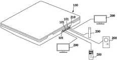
일반적으로, 노트북 또는 개인용 컴퓨터(100)의 패널 일면에는 TV, 모니터, 스피커, 마이크, 빔프로젝터 등 다양한 외부기기(200)를 각기 연결하는 복수개의 외부기기 연결단자(101)들이 도 1에서와 같이 설치되는 것이며, 이같은 외부기기 연결단자(101)들은 하나의 패널부에 집중되어 연결단자 유닛(210)을 이루고 있다.In general, a plurality of external
상기 연결단자 유닛(210)은 복수개의 외부기기 연결단자(101)를 통해 접속되는 상기 복수개의 외부기기(200)에 상기 컴퓨터(100)에 저장되어 있는 소프트웨어와 연동하여 출력신호를 영상 또는 소리의 형태로 유.무선 전송하게 된다.The
그러나, 상기 외부기기 연결단자(101)에 연결되는 상기 외부기기(200)들은 상기 컴퓨터(100)에 내장되어 있는 소프트웨어의 오류 또는 사용자의 조작 실수로 인해 의도되지 않은 출력신호가 전달되거나 출력되는 사례를 경험하게 되는 것이었으며, 이같은 출력되는 불필요한 영상 또는 소리 등은 중요한 회의나 공연, 집회 등을 방해하는 주요 요인으로 작용하게 되는 것이었다. 이러한 불편은 가정에서 사용되는 오디오.영상기기 시스템에 적용됨에 있어서도 예외는 아니었다.However, the
본 발명은 상기와 같은 문제점을 해결하기 위해 제안된 것으로서, 컴퓨터에 구비된 외부기기 연결단자 유닛의 각 연결단자에, 복수개의 제어스위치로 이루어지는 출력신호 발신차단용 제어스위치패널를 부가 설치하여 줌으로서, 외부기기 연결단자에 연결된 외부기기로 불필요한 입력신호 또는 출력신호가 전달되는 현상을 방지하는데 그 주된 목적이 있다.The present invention has been proposed to solve the above problems, by providing a control switch panel for output signal transmission blocking consisting of a plurality of control switches to each connection terminal of the external device connection terminal unit provided in the computer, Its main purpose is to prevent unnecessary input signals or output signals from being transmitted to external devices connected to external device connection terminals.
본 발명의 다른 목적은, 컴퓨터에 저장된 프로그램을 통해 구현되는 복수개의 외부기기 중 필요로 하는 외부기기 신호만을 제어스위치 조작을 통해 또는 리모콘 제어를 통해 선택적으로 송출할 수 있도록 하려는 것이다.Another object of the present invention is to be able to selectively transmit only the external device signals required by a plurality of external devices implemented through a program stored in a computer through a control switch operation or a remote control.
본 발명의 또 다른 목적은, 자체모니터 영상출력 차단스위치를 사용함으로서, 노트북에 적용시 노트북이 열려 있거나 덮개를 닫은 상태에 구애됨이 없이 연결된 외부기기가 효과적으로 동작될 수 있도록 하려는 것이다.Still another object of the present invention is to use the self-monitoring video output cut-off switch, so that the connected external device can be effectively operated without the notebook being open or closed when applied to the notebook.
본 발명의 또 다른 목적은, 무선네트워크를 이용한 출력시스템 적용시 제어스위치들이 무선네트워크 안테나 출력차단스위치로 대체 기능하는 외부기기 연결단자 제어스위치를 갖는 컴퓨터를 제공하려는 것이다.It is still another object of the present invention to provide a computer having a control switch for connecting external devices, in which control switches replace a wireless network antenna output cut-off switch when an output system using a wireless network is applied.
이와 같은 목적을 달성하기 위해서, 본 발명은 복수개의 외부기기들을 접속할 수 있도록 다수개의 외부기기 연결단자를 구비한 연결단자 유닛을 갖는 컴퓨터에 있어서, 상기 연결단자 유닛의 각 외부기기 연결단자들이, 외부기기 연결단자들로 입력 또는 출력되는 신호를 각기 온/오프 제어하는 복수개의 출력신호 발신차단용 제어스위치를 경유하도록 설치되는 것을 특징으로 한다.In order to achieve the above object, the present invention provides a computer having a connection terminal unit having a plurality of external device connection terminals to connect a plurality of external devices, each of the external device connection terminals of the connection terminal unit, It is characterized in that it is installed so as to pass through a plurality of output signal transmission blocking control switches for controlling the input or output signal to the device connection terminals, respectively.
본 발명의 일면에 따라, 상기 복수개의 출력신호 발신차단용 제어스위치들이, 컴퓨터의 일면으로 노출되는 외부기기 연결단자에 근접하게 내장된 구조로 설치될 수 있다.According to an aspect of the present invention, the plurality of output signal transmission blocking control switches may be installed in a structure that is built in close proximity to the external terminal connection terminal exposed to one side of the computer.
본 발명의 일면에 따라, 상기 복수개의 출력신호 발신차단용 제어스위치들이, 컴퓨터의 외부로 노출되며 접속케이블로 연결되는 외장형의 컨트롤박스에 설치될 수 있다.According to an aspect of the present invention, the plurality of output signal transmission blocking control switches may be installed in an external control box exposed to the outside of the computer and connected by a connection cable.
본 발명의 또 다른 일면에 따라, 상기 외부기기 연결단자 유닛의 각 외부기기 연결단자들이 각각의 출력신호 발신차단용 제어스위치들과 대응되도록 설치된다.According to another aspect of the present invention, each external device connection terminal of the external device connection terminal unit is provided to correspond to the control switch for the output signal transmission block.
본 발명의 또 다른 일면에 따라, 상기 출력신호 발신차단용 제어스위치의 온/오프 상태를 표시하도록 상기 출력신호 발신차단용 제어스위치에 온/오프 표시등을 더 구성할 수 있다.According to still another aspect of the present invention, an on / off indicator may be further configured on the output signal transmission blocking control switch to display an on / off state of the output signal transmission blocking control switch.
본 발명의 또 다른 일면에 따라, 상기 출력신호 발신차단용 제어스위치는 리모콘에 의해 온/오프 제어되는 것을 특징으로 한다.According to another aspect of the invention, the output signal transmission blocking control switch is characterized in that the on / off control by the remote control.
본 발명의 또 다른 일면에 따라, 상기 출력신호 발신차단용 제어스위치패널에는 자체모니터 영상출력 차단스위치를 더 구비하는 것을 특징으로 한다.According to another aspect of the invention, the output signal transmission blocking control switch panel is characterized in that it further comprises a self-monitoring video output cut-off switch.
본 발명의 또 다른 일면에 따라, 상기 출력신호 발신차단용 제어스위치들이 무선네트워크 안테나 출력차단스위치로 대체 기능하는 것을 특징으로 한다.According to yet another aspect of the present invention, the output signal control switch for the transmission is characterized in that the replacement function of the wireless network antenna output switch.
본 발명은, 컴퓨터에 구비된 외부기기 연결단자 유닛의 각 연결단자에, 복수개의 제어스위치로 이루어지는 출력신호 발신차단용 제어스위치패널를 부가 설치하여 줌으로서, 외부기기 연결단자에 연결된 외부기기로 불필요한 입력신호 또는 출력신호가 전달되는 현상을 방지하는데 유익하며, 더욱이 컴퓨터에 저장된 프로그램을 통해 구현되는 복수개의 외부기기 중 필요로 하는 외부기기 신호만을 제어스위치 조작을 통해 또는 리모콘 제어를 통해 선택적으로 송출할 수 있게 되는 것이다.According to the present invention, a control switch panel for output signal transmission blocking comprising a plurality of control switches is attached to each connection terminal of an external device connection terminal unit provided in a computer, thereby unnecessary input to an external device connected to the external device connection terminal. This is useful for preventing the signal or output signal from being transmitted. Furthermore, only the external device signals required by a plurality of external devices implemented through a program stored in a computer can be selectively transmitted through a control switch operation or a remote control. Will be.
본 발명은 또한, 자체모니터 영상출력 차단스위치를 사용함으로서, 노트북에 적용시 노트북이 열려 있거나 덮개를 닫은 상태에 구애됨이 없이 연결된 외부기기가 효과적으로 동작될 수 있게 되는 것이고, 더 나아가 무선네트워크를 이용한 출력시스템 적용시 출력신호 발신차단용 제어스위치들이 무선네트워크 안테나 출력차단스위치로 대체 기능하는 것이다.In another aspect, the present invention, by using the self-monitoring video output cut-off switch, when connected to the notebook, the connected external device can be effectively operated without regard to the notebook open or closed the cover, and furthermore, using a wireless network When the output system is applied, the control switch for output signal transmission cut off is replaced by the wireless network antenna output cut off switch.
도 1은 종래의 컴퓨터 외부기기 연결단자에 다수의 외부기기를 연결 설치하고 있는 외부기기 설치구조를 보인 구성 개략도.
도 2는 본 발명의 일실시예에 따른, 출력신호 발신차단용 제어스위치패널의 내장형 설치상태 및 그 특징부를 확대하여 나타낸 도면.
도 3은 본 발명의 일실시예에 따른, 출력신호 발신차단용 제어스위치와 외부기기 연결단자의 결합 단면도.
도 4는 본 발명의 다른 실시예에 따른, 출력신호 발신차단용 제어스위치패널의 외장형 설치상태 및 그 특징부를 확대하여 나타낸 도면.
도 5은 본 발명의 다른 실시예에 따른, 출력신호 발신차단용 제어스위치와 외부기기 연결단자의 결합 단면도 이다.1 is a schematic view showing an external device installation structure in which a plurality of external devices are connected and installed in a conventional computer external device connection terminal.
Figure 2 is an enlarged view showing the built-in installation state and its features of the control switch panel for output signal transmission blocking according to an embodiment of the present invention.
Figure 3 is a cross-sectional view of the coupling between the output signal transmission blocking control switch and the external device connection terminal according to an embodiment of the present invention.
Figure 4 is an enlarged view showing the external installation state and its features of the control switch panel for output signal transmission blocking according to another embodiment of the present invention.
5 is a cross-sectional view illustrating a combination of an output signal transmission blocking control switch and an external device connection terminal according to another embodiment of the present invention.
본 발명을 충분히 이해하기 위해서 본 발명의 바람직한 실시예를 첨부 도면을 참조하여 설명한다.For a better understanding of the present invention, a preferred embodiment of the present invention will be described with reference to the accompanying drawings.
본 발명에서 '컴퓨터'라 함은 노트북을 포함하는 개인용 PC를 의미하며, 확장된 의미로서 프린터나 스피커 등 외부기기를 연결하여 사용하기 연결단자를 구비하는 또다른 형태의 기기, 예로서 전자사전이나 전자수첩, 전자북, 테플릿PC, 무선키보드PC, PMP, 하드네트워크 등을 포함하게 된다.In the present invention, the term "computer" refers to a personal PC including a notebook, and in an extended meaning, another type of device having a connection terminal for connecting and using an external device such as a printer or a speaker, for example, an electronic dictionary or It will include electronic notebooks, electronic books, tablet PCs, wireless keyboard PCs, PMPs, and hard networks.
본 발명의 실시예는 여러가지 형태로 변형될 수 있으며, 본 발명의 범위가 아래에서 상세히 설명하는 실시예로 한정되는 것으로 해석되어서는 안된다. 본 실시예는 당업계에서 평균적인 지식을 가진 자에게 본 발명을 보다 안전하게 설명하기 위하여 제공되는 것이다.The embodiments of the present invention may be modified in various forms, and the scope of the present invention should not be construed as being limited to the embodiments described in detail below. The present embodiments are provided to explain the present invention more safely to those having ordinary skill in the art.
또한, 본 발명의 요지를 불필요하게 흐릴 수 있다고 판단되는 공지 기능 및 구성에 대한 상세한 기술은 생략된다.In addition, detailed descriptions of well-known functions and configurations that are determined to unnecessarily obscure the subject matter of the present invention are omitted.
도 2는 본 발명의 일실시예에 따른, 출력신호 발신차단용 제어스위치패널의 내장형 설치상태 및 그 특징부를 확대하여 나타낸 도면이고, 도 3은 본 발명의 일실시예에 따른, 출력신호 발신차단용 제어스위치와 외부기기 연결단자의 결합 단면도를 각각 도시하고 있다.Figure 2 is an enlarged view showing the built-in installation state and its features of the control switch panel for output signal transmission blocking according to an embodiment of the present invention, Figure 3 is an output signal transmission blocking according to an embodiment of the present invention The sectional view of the coupling between the control switch and the external device connecting terminal is shown.
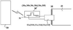
또한, 도 4는 본 발명의 다른 실시예에 따른, 출력신호 발신차단용 제어스위치패널의 외장형 설치상태 및 그 특징부를 확대하여 나타낸 도면이며, 도 5은 본 발명의 다른 실시예에 따른, 출력신호 발신차단용 제어스위치와 외부기기 연결단자의 결합 단면도를 각각 도시하고 있는 것이다.4 is an enlarged view of an external installation state and features of an output signal transmission blocking control switch panel according to another embodiment of the present invention, and FIG. 5 is an output signal according to another embodiment of the present invention. Fig. 1 shows a cross sectional view of a combination of a control switch for blocking transmission and a connection terminal of an external device.
본 발명에 따른 내장형 구조의 외부기기 연결단자 제어스위치를 갖는 컴퓨터는 도 2 및 도 3에 도시된 것을 참조하여 상세하게 설명하면 다음과 같다.A computer having an external device connection terminal control switch of a built-in structure according to the present invention will be described in detail with reference to those shown in FIGS. 2 and 3.
본 발명에 따른 외부기기 연결단자 제어스위치를 내장된 구조로 구비하고 있는 컴퓨터는, 외부기기 연결단자 유닛(10)과, 복수개의 출력신호 발신차단용 제어스위치(30a)(30b)(30c)(30d)(30e)(30f)들로 구성된다.The computer equipped with the external device connection terminal control switch according to the present invention has a built-in structure, the external device
상기 외부기기 연결단자 유닛(10)은 도 2 내지 도 5에 도시하는 바와 같이, 단자 체결구조의 컴퓨터(20) 일면에 노출되는 상태로 설치될 수 있으며, 더욱 구체적으로는 상기 컴퓨터(20)의 키보드가 위치하는 커버체의 여백부 일면에 접근 용이하게 설치될 수 있다. 그러나, 이같은 연결단자 유닛(10)은 상기 컴퓨터(20)의 외부 측면이나 그 둘레면에 설치될 수도 있으며, 그 위치는 본 발명이 추구하는 기능 실현에 장애가 되지 않는 한 특정할 필요는 없다.As shown in FIGS. 2 to 5, the external device
상기 외부기기 연결단자 유닛(10)에는 다수개의 외부기기 연결단자(11a)(11b)(11c)(11d)(11e)(11f)들이 배치된다. 이들 외부기기 연결단자(11a)(11b)(11c)(11d)(11e)(11f)들은 외부기기와 접속되어 영상 또는 소리가 유.무선의 방법으로 입력 또는 출력되도록 구성된다.The external device
상기 외부기기 연결단자(11a)(11b)(11c)(11d)(11e)(11f)들은 외부기기인 TV, 빔프로젝터, 컴퓨터(PC), 스피커, 마이크가 접속할 수 있는 HDMI/DVI단자(HDMI/DVI), PC출력단자(PC OUT), 모니터출력단자(MONITOR OUT)와, 다른 외부기기의 스피커가 접속할 수 있는 사운드 입출력단자(SOUND IN/ SOUND OUT), 또 다른 외부기기의 마이크가 접속할 수 있는 마이크 출력단자(MIC OUT) 등으로 구성되어 지며, 여기에는 필요에 따라 선택적으로 탑재될 기능을 구현하는데 필요한 외부기기 연결용 예비단자가 포함될 수 있다.The external
상기한 외부기기가 외부기기 연결단자(11a)(11b)(11c)(11d)(11e)(11f)들 중 어느 하나에 또는 이들 모두에 1:1로 대응되게 접속되면, 상기 컴퓨터(20)의 소프트웨어는 외부기기로 영상 또는 소리를 유.무선 출력하거나, 외부기기에서 상기 외부기기 연결단자(11a)(11b)(11c)(11d)(11e)(11f)들을 통해 상기 컴퓨터(20)에 입력되도록 구성된다.When the external device is connected to one or both of the external
이러한 영상 또는 소리와 같은 입력 또는 출력되는 신호를 상기 외부기기 연결단자(11a)(11b)(11c)(11d)(11e)(11f)들에서 차단하기 위해, 상기 외부기기 연결단자(11a)(11b)(11c)(11d)(11e)(11f)들의 입력 또는 출력되는 신호가 출력신호 발신차단용 제어스위치(30a)(30b)(30c)(30d)(30e)(30f)들 각각에 대하여 1:1로 경유하도록 설치한다.In order to block an input or output signal such as an image or a sound from the external
즉, 상기 외부기기 연결단자(11a)(11b)(11c)(11d)(11e)(11f)들의 입력신호 및 출력신호를 상기 출력신호 발신차단용 제어스위치(30a)(30b)(30c)(30d)(30e)(30f)들을 1:1로 경유하도록 구성하여 줌으로서, 상기 출력신호 발신차단용 제어스위치(30a)(30b)(30c)(30d)(30e)(30f)들에서 상기 외부기기 연결단자들로 보내어지는 입력신호 및 출력신호를 각기 차단 또는 통과하도록 하는 것이다.That is, the
이때, 상기 출력신호 발신차단용 제어스위치(30a)(30b)(30c)(30d)(30e)(30f)들에는, 자체모니터 영상출력 차단스위치(30g)를 더 구비할 수 있다.In this case, the output signal transmission
상기 출력신호 발신차단용 제어스위치(30a)(30b)(30c)(30d)(30e)(30f)들에 인접하게 설치되는 상기 자체모니터 영상출력 차단스위치(30g)는 노트북 등에 적용시 자체모니터의 영상이 외부기기로 출력되는 것을 차단하게 되는 것이므로, 노트북을 개방한 상태는 물론 덮개를 닫은 상태에서도 연결된 외부기기가 효과적으로 동작될 수 있도록 하는 기능을 구현하게 된다.The self-monitoring image output cut-
또한, 상기 출력신호 발신차단용 제어스위치(30a)(30b)(30c)(30d)(30e)(30f)들은 이를 무선네트워크 안테나 출력차단스위치로 대체 기능하도록 구성할 수 있는데, 이 경우 무선네트워크를 이용한 출력시스템에 적용할 시 각각의 출력신호 발신차단용 제어스위치(30a)(30b)(30c)(30d)(30e)(30f)들이 무선네트워크 안테나 출력차단스위치로서 기능하게 된다.In addition, the
상기 출력신호 발신차단용 제어스위치(30a)(30b)(30c)(30d)(30e)(30f)들은 복수개로 구비하여 제어스위치패널(30) 위에 구성된다. 따라서 이들 각각의 제어스위치들은 상기 외부기기 연결단자(11a)(11b)(11c)(11d)(11e)(11f)들을 구비하고 있는 외부기기 연결단자 유닛(10)과 대응되는 쌍의 구조를 이루게 되는 것이다.The output signal transmission
상기 출력신호 발신차단용 제어스위치(30a)(30b)(30c)(30d)(30e)(30f)들로 상기 외부기기에 상기 외부기기 연결단자(11a)(11b)(11c)(11d)(11e)(11f)들에서 입력 또는 출력되는 신호인 영상 또는 소리를 온/오프하도록 구성한다.The external
이는 컴퓨터(20)의 소프트웨어의 오류로 인해, 또는 컴퓨터(20)를 이용하는 이용자의 실수로 인해서 상기 컴퓨터(20)에 설치된 외부기기 연결단자(11a)(11b)(11c)(11d)(11e)(11f)들 중 어느 하나에서 출력되는 불필요한 신호인 영상 또는 소리를 상기 외부기기 연결단자(11a)(11b)(11c)(11d)(11e)(11f)들에 접속된 상기 외부기기로 전달되는 것을 차단하기 위함이다.This is caused by an error in the software of the
도 5는 본 발명의 다른 실시예로서, 상기 출력신호 발신차단용 제어스위치(30a)(30b)(30c)(30d)(30e)(30f)들이 리모콘(50)에 의해 제어되는 무선제어스위치(30')로 구성된 구조를 예시하고 있다.5 is another embodiment of the present invention, the output signal transmission blocking
상기 리모콘(50)은 복수개의 출력신호 발신차단용 제어스위치(30a)(30b)(30c)(30d)(30e)(30f)들 각각을 대체하게 되는 상기 무선제어스위치(30')에 온/오프 제어신호를 보내어 상기 무선제어스위치(30a')를 온/오프되도록 구성된다.The
상기 리모콘(50)과 상기 무선제어스위치(30')의 조합으로 구성하는 경우에는 가정에서 사용하는 오디오/영상기기의 간편한 제어는 물론, 회의, 공연, 집회장소 등과 같이 넓은 공간에 설치된 상기 컴퓨터(20) 및 상기 외부기기를 사용자가 접근성이 용이하지 못할 경우라도 간편하게 제어할 수 있도록 하기 위함이다.In the case of the combination of the
복수의 출력신호 발신차단용 제어스위치(30a)(30b)(30c)(30d)(30e)(30f)들은 도 2에서 보이고 있듯이 상기 컴퓨터(20)의 일면으로 노출되는 제어스위치패널(30)에 접근이 용이하게 설치할 수 있음은 물론, 도 4에서 보여주는 바와 같이 노트북으로부터 분리된 별도의 스위치박스의 구조로 설치할 수 있게 된다.As shown in FIG. 2, the
즉, 상기 제어스위치패널(30)는 상기 컴퓨터(20)가 노트북일 경우 상기 노트북에 설치된 키보드(21)의 상부면에 설치하는 것이 바람직하나, 상기 출력신호 발신차단용 제어스위치패널(30)의 설치되는 위치는 상기 컴퓨터(20)의 외부면 한 특정부위를 한정하지는 않는다.That is, the
이는 도 2 및 도 3에 도시하는 바와 같이, 복수개의 출력신호 발신차단용 제어스위치(30a)(30b)(30c)(30d)(30e)(30f)들로 구성되는 상기 제어스위치패널(30)이 상기 컴퓨터(20)의 일면으로 노출되어 접근이 용이한 위치에 설치됨으로서 상기 제어스위치패널(30)이 상기 컴퓨터(20)와 일체를 이루는 내장형의 구조를 설명하고자 함이다.2 and 3, the
그러나 본 발명은, 도 4 및 도 5에 도시하는 바와 같이, 상기 복수개의 출력신호 발신차단용 제어스위치(30a)(30b)(30c)(30d)(30e)(30f)들이 상기 컴퓨터(20)의 외부로 노출되며 접속케이블로 연결되는 외장형 컨트롤박스 유닛(31)의 상부 제어스위치패널(30')에 설치된 구조에 의해서도 효과적으로 그 목적들을 달성할 수 있게 된다.However, in the present invention, as shown in Figs. 4 and 5, the
한편, 상기 출력신호 발신차단용 제어스위치(30a)(30b)(30c)(30d)(30e)(30f)들에는 온/오프 표시등(40)을 더 설치할 수 있는데, 이같은 온/오프 표시등(40)은 상기 출력신호 발신차단용 제어스위치(30a)(30b)(30c)(30d)(30e)(30f)들의 온/오프상태를 시각적으로 확인할 수 있도록 하기 위함이다.On the other hand, the on / off
이러한 온/오프 표시등(40)은 도시하는 바와 같이 상기 출력신호 발신차단용 제어스위치(30a)(30b)(30c)(30d)(30e)(30f)들에 인접하게 분리된 구조로 설치될 수 있을 것이나, 출력신호 발신차단용 제어스위치(30a)(30b)(30c)(30d)(30e)(30f)들 각각에 일체형으로 구성될 수도 있다. 스위치 일체형으로 구성하는 경우, 출력신호 발신차단용 제어스위치(30a)(30b)(30c)(30d)(30e)(30f)들의 둘레면에 또는 제어스위치(30a)(30b)(30c)(30d)(30e)(30f)들 버튼 중앙에 LED램프를 적용하여 조명이 없는 장소에서도 원하는 스위치를 용이하게 조작할 수 있을 것임은 물론이다.The on / off
이상에서 설명된 본 발명에 따른 실시예는 예시적인 것에 불과하며, 본 발명이 속하는 기술분야의 통상의 지식을 가진 자라면 이로부터 다양한 변형 및 균등한 타 실시예가 가능하다는 점을 잘 알 수 있을 것이다. 그러므로 본 발명은 상기의 상세한 설명에서 언급되는 형태로만 한정되는 것은 아님을 잘 이해할 수 있을 것이다.It will be apparent to those skilled in the art that various modifications and equivalent arrangements may be made therein without departing from the scope of the present invention. . Therefore, it is to be understood that the present invention is not limited to the above-described embodiments.
따라서 본 발명의 진정한 기술적 보호범위는 첨부된 특허청구범위의 기술적 사상에 의해 정해져야 할 것이다. 또한, 본 발명은 첨부된 청구범위에 의해 정의되는 본 발명의 정신과 그 범위내에 있는 모든 변형물과 균등물 및 대체물을 포함하는 것으로 이해되어야 한다.Accordingly, the true scope of the present invention should be determined by the technical idea of the appended claims. It is also to be understood that the present invention includes all modifications, equivalents and substitutions within the spirit and scope of the invention as defined by the appended claims.
10: 연결단자 유닛
11a,11b,11c,11d,11e,11f: 외부기기 연결단자
20: 컴퓨터
30,30': 제어스위치패널
30a,30b,30c,30d,30e,30f: 출력신호 발신차단용 제어스위치
30g: 자체모니터 영상출력 차단스위치
31: 컨트롤박스 유닛
40: 온/오프 표시등
50: 리모콘10: Terminal unit
11a, 11b, 11c, 11d, 11e, 11f: External device connection terminal
20: computer
30,30 ': control switch panel
30a, 30b, 30c, 30d, 30e, 30f: Output switch control switch
30g: Self-monitoring video output disconnect switch
31: control box unit
40: on / off indicator light
50: remote control
Claims (8)
Translated fromKorean상기 연결단자 유닛(10)의 각 외부기기 연결단자(11a)(11b)(11c)(11d)(11e)(11f)들이, 외부기기 연결단자(11a)(11b)(11c)(11d)(11e)(11f)들로 입력 또는 출력되는 신호를 각기 온/오프 제어하는 복수개의 출력신호 발신차단용 제어스위치(30a)(30b)(30c)(30d)(30e)(30f)들을 경유하도록 설치하고,
상기 출력신호 발신차단용 제어스위치(30a)(30b)(30c)(30d)(30e)(30f)들의 온/오프 상태를 표시하도록 상기 출력신호 발신차단용 제어스위치(30a)(30b)(30c)(30d)(30e)(30f)들에 온/오프 표시등(40)을 더 설치하여 구성한 것을 특징으로 하는 외부기기 연결단자 제어스위치를 갖는 컴퓨터.In a computer (20) having a connection terminal unit (10) having a plurality of external device connection terminals (11a) (11b) (11c) (11d) (11e) (11f) to connect a plurality of external devices,
Each external device connection terminal 11a, 11b, 11c, 11d, 11e, 11f of the connection terminal unit 10 is connected to the external device connection terminal 11a, 11b, 11c, 11d ( 11e) are installed to pass through a plurality of output signal control switch 30a, 30b, 30c, 30d, 30e, 30f for turning on / off a signal input or output to 11f, respectively. and,
Control switch 30a, 30b, 30c for output signal transmission blocking to display the on / off state of the control signal transmission block 30a, 30b, 30c, 30d, 30e, 30f. (30d) (30e) A computer having an external device connection terminal control switch, characterized in that the on / off indicator 40 is further installed in the configuration.
상기 복수개의 출력신호 발신차단용 제어스위치(30a)(30b)(30c)(30d)(30e)(30f)들이, 컴퓨터(20)의 일면으로 노출되는 외부기기 연결단자(11a)(11b)(11c)(11d)(11e)(11f)들에 근접하게 내장된 구조로 설치되는 것을 특징으로 하는 외부기기 연결단자 제어스위치를 갖는 컴퓨터.The method of claim 1,
The control switches 30a, 30b, 30c, 30d, 30e, and 30f of the plurality of output signal transmission cutoffs are connected to external device terminals 11a and 11b exposed to one surface of the computer 20. 11c) (11d) (11e) A computer having an external device connecting terminal control switch, characterized in that it is installed in a built-in structure close to the (11f).
상기 연결단자 유닛(10)의 각 외부기기 연결단자(11a)(11b)(11c)(11d)(11e)(11f)들이, 외부기기 연결단자(11a)(11b)(11c)(11d)(11e)(11f)들로 입력 또는 출력되는 신호를 각기 온/오프 제어하는 복수개의 출력신호 발신차단용 제어스위치(30a)(30b)(30c)(30d)(30e)(30f)들을 경유하도록 설치하되,
상기 복수개의 출력신호 발신차단용 제어스위치(30a)(30b)(30c)(30d)(30e)(30f)들이, 컴퓨터(20)의 외부로 노출되며 접속케이블로 연결되는 외장형의 컨트롤박스 유닛(31)에 설치되는 것을 특징으로 하는 외부기기 연결단자 제어스위치를 갖는 컴퓨터.In a computer (20) having a connection terminal unit (10) having a plurality of external device connection terminals (11a) (11b) (11c) (11d) (11e) (11f) to connect a plurality of external devices,
Each external device connection terminal 11a, 11b, 11c, 11d, 11e, 11f of the connection terminal unit 10 is connected to the external device connection terminal 11a, 11b, 11c, 11d ( 11e) are installed to pass through a plurality of output signal control switch 30a, 30b, 30c, 30d, 30e, 30f for turning on / off a signal input or output to 11f, respectively. But
The control box unit 30a, 30b, 30c, 30d, 30e, 30f of the plurality of output signal transmission cutoff are exposed to the outside of the computer 20 and connected with a connection cable. 31) A computer having a control switch for connecting external equipment, characterized in that being installed in.
외부기기 연결단자 유닛(10)의 각 외부기기 연결단자(11a)(11b)(11c)(11d)(11e)(11f)들이 각각의 출력신호 발신차단용 제어스위치(30a)(30b)(30c)(30d)(30e)(30f)들과 대응되도록 설치되는 것을 특징으로 하는 외부기기 연결단자 제어스위치를 갖는 컴퓨터.The method of claim 1,
Each of the external device connection terminals 11a, 11b, 11c, 11d, 11e, and 11f of the external device connection terminal unit 10 control switches 30a, 30b, and 30c for output signal transmission blocking. (30d) (30e) is a computer having a control terminal for connecting the external device, characterized in that it is installed so as to correspond to.
상기 출력신호 발신차단용 제어스위치(30a)(30b)(30c)(30d)(30e)(30f)들의 온/오프 상태를 표시하도록 상기 출력신호 발신차단용 제어스위치(30a)(30b)(30c)(30d)(30e)(30f)들에 온/오프 표시등(40)을 더 설치하여 구성된 것을 특징으로 하는 외부기기 연결단자 제어스위치를 갖는 컴퓨터.The method of claim 3, wherein
Control switch 30a, 30b, 30c for output signal transmission blocking to display the on / off state of the control signal transmission block 30a, 30b, 30c, 30d, 30e, 30f. (30d) 30e (30e) A computer having an external device connecting terminal control switch, characterized in that the on / off indicator 40 is further installed to install.
상기 출력신호 발신차단용 제어스위치(30a)(30b)(30c)(30d)(30e)(30f)들은 리모콘(50)에 의해 온/오프 제어되는 것을 특징으로 하는 외부기기 연결단자 제어스위치를 갖는 컴퓨터.The method according to any one of claims 1 to 4,
The control switch 30a, 30b, 30c, 30d, 30e, 30f for output signal transmission blocking has an external device connection terminal control switch, which is controlled on / off by the remote controller 50. computer.
상기 출력신호 발신차단용 제어스위치(30a)(30b)(30c)(30d)(30e)(30f)들은 자체모니터 영상출력 차단스위치(30g)를 더 구비하는 것을 특징으로 하는 외부기기 연결단자 제어스위치를 갖는 컴퓨터.The method according to any one of claims 1 to 4,
The control switch 30a, 30b, 30c, 30d, 30e, 30f for output signal transmission blocking further comprises a self-monitoring image output disconnect switch 30g. Having a computer.
상기 출력신호 발신차단용 제어스위치(30a)(30b)(30c)(30d)(30e)(30f)들이 무선네트워크 안테나 출력차단스위치로 대체 기능하는 것을 특징으로 하는 외부기기 연결단자 제어스위치를 갖는 컴퓨터.The method according to any one of claims 1 to 4,
The computer having an external device connection terminal control switch, characterized in that the control switch (30a) (30b) (30c) (30d) (30e) (30f) for the output signal transmission cut off function as a wireless network antenna output cutoff switch. .
Priority Applications (2)
| Application Number | Priority Date | Filing Date | Title |
|---|---|---|---|
| KR1020120029139AKR101192524B1 (en) | 2012-03-22 | 2012-03-22 | External apparatus connector unit control switch for computer |
| PCT/KR2013/001632WO2013141497A1 (en) | 2012-03-22 | 2013-02-28 | Computer provided with control switch for connection terminal for external devices |
Applications Claiming Priority (1)
| Application Number | Priority Date | Filing Date | Title |
|---|---|---|---|
| KR1020120029139AKR101192524B1 (en) | 2012-03-22 | 2012-03-22 | External apparatus connector unit control switch for computer |
Publications (1)
| Publication Number | Publication Date |
|---|---|
| KR101192524B1true KR101192524B1 (en) | 2012-10-17 |
Family
ID=47288248
Family Applications (1)
| Application Number | Title | Priority Date | Filing Date |
|---|---|---|---|
| KR1020120029139AExpired - Fee RelatedKR101192524B1 (en) | 2012-03-22 | 2012-03-22 | External apparatus connector unit control switch for computer |
Country Status (2)
| Country | Link |
|---|---|
| KR (1) | KR101192524B1 (en) |
| WO (1) | WO2013141497A1 (en) |
Citations (2)
| Publication number | Priority date | Publication date | Assignee | Title |
|---|---|---|---|---|
| KR200279081Y1 (en)* | 2002-03-21 | 2002-06-22 | 윤호형 | A computer's key board attached exchange switch for speaker and headsets |
| JP2005509947A (en) | 2001-11-09 | 2005-04-14 | エイテン テクノロジー, インク. | Signal switch for console devices and peripheral devices |
Family Cites Families (3)
| Publication number | Priority date | Publication date | Assignee | Title |
|---|---|---|---|---|
| KR940015765A (en)* | 1992-12-31 | 1994-07-21 | 이헌조 | Floppy disk changer and replacement method of computer |
| TW585799B (en)* | 2000-03-01 | 2004-05-01 | Sony Computer Entertainment Inc | Electronic equipment communications system and repeater |
| US8271815B2 (en)* | 2010-01-25 | 2012-09-18 | J.R.J. Electronic Co., Ltd. | Device for controlling power to a plurality of peripherals based on the state of a host computer |
- 2012
- 2012-03-22KRKR1020120029139Apatent/KR101192524B1/ennot_activeExpired - Fee Related
- 2013
- 2013-02-28WOPCT/KR2013/001632patent/WO2013141497A1/enactiveApplication Filing
Patent Citations (2)
| Publication number | Priority date | Publication date | Assignee | Title |
|---|---|---|---|---|
| JP2005509947A (en) | 2001-11-09 | 2005-04-14 | エイテン テクノロジー, インク. | Signal switch for console devices and peripheral devices |
| KR200279081Y1 (en)* | 2002-03-21 | 2002-06-22 | 윤호형 | A computer's key board attached exchange switch for speaker and headsets |
Also Published As
| Publication number | Publication date |
|---|---|
| WO2013141497A1 (en) | 2013-09-26 |
Similar Documents
| Publication | Publication Date | Title |
|---|---|---|
| ES2659773T3 (en) | Using a control panel as a wireless access point | |
| US11006071B2 (en) | Integrated telemedicine device | |
| EP2685387B1 (en) | Secure peripheral connecting device | |
| KR101459059B1 (en) | Physical network switching apparatus for dual monitor | |
| KR102609515B1 (en) | Connector apparatus and display apparatus having thereof | |
| CN115606169A (en) | Security Conference Equipment | |
| KR101615994B1 (en) | Integral isolation network with all in one personal computer | |
| US20120229973A1 (en) | Tablet personal computer | |
| KR101192524B1 (en) | External apparatus connector unit control switch for computer | |
| EP3285482A1 (en) | Television mainboard device and television system | |
| WO2020093373A1 (en) | Electronic device and scalable device | |
| US20070097068A1 (en) | Display apparatus and information processing apparatus | |
| KR101446204B1 (en) | A combination control device for electric teaching table | |
| US20140363167A1 (en) | Electronic device having remote control functions | |
| CN209375801U (en) | Large screen switching matrix box | |
| US20190113951A1 (en) | System, method and apparatus for smart multiple devices | |
| CN202406407U (en) | Multifunctional remote controller for household appliance | |
| JP3178421U (en) | Input device having Bluetooth multiple identification module | |
| CN204256666U (en) | A kind of Novel computer peripheral equipment | |
| KR101432626B1 (en) | Physical devision apparatus of local network and external network | |
| JP6264590B2 (en) | Keyboard device and computer assembly having an operating system | |
| CN219999432U (en) | Portable video conference terminal equipment | |
| CN221575451U (en) | Multiple-in-one-out switcher | |
| CN217060863U (en) | Notebook computer | |
| CN111131731B (en) | Novel split television |
Legal Events
| Date | Code | Title | Description |
|---|---|---|---|
| A201 | Request for examination | ||
| A302 | Request for accelerated examination | ||
| PA0109 | Patent application | St.27 status event code:A-0-1-A10-A12-nap-PA0109 | |
| PA0201 | Request for examination | St.27 status event code:A-1-2-D10-D11-exm-PA0201 | |
| PA0302 | Request for accelerated examination | St.27 status event code:A-1-2-D10-D17-exm-PA0302 St.27 status event code:A-1-2-D10-D16-exm-PA0302 | |
| D13-X000 | Search requested | St.27 status event code:A-1-2-D10-D13-srh-X000 | |
| D14-X000 | Search report completed | St.27 status event code:A-1-2-D10-D14-srh-X000 | |
| E902 | Notification of reason for refusal | ||
| PE0902 | Notice of grounds for rejection | St.27 status event code:A-1-2-D10-D21-exm-PE0902 | |
| P11-X000 | Amendment of application requested | St.27 status event code:A-2-2-P10-P11-nap-X000 | |
| P13-X000 | Application amended | St.27 status event code:A-2-2-P10-P13-nap-X000 | |
| E701 | Decision to grant or registration of patent right | ||
| PE0701 | Decision of registration | St.27 status event code:A-1-2-D10-D22-exm-PE0701 | |
| GRNT | Written decision to grant | ||
| PR0701 | Registration of establishment | St.27 status event code:A-2-4-F10-F11-exm-PR0701 | |
| PR1002 | Payment of registration fee | St.27 status event code:A-2-2-U10-U11-oth-PR1002 Fee payment year number:1 | |
| PG1601 | Publication of registration | St.27 status event code:A-4-4-Q10-Q13-nap-PG1601 | |
| R18-X000 | Changes to party contact information recorded | St.27 status event code:A-5-5-R10-R18-oth-X000 | |
| FPAY | Annual fee payment | Payment date:20150826 Year of fee payment:4 | |
| PR1001 | Payment of annual fee | St.27 status event code:A-4-4-U10-U11-oth-PR1001 Fee payment year number:4 | |
| PR1001 | Payment of annual fee | St.27 status event code:A-4-4-U10-U11-oth-PR1001 Fee payment year number:5 | |
| LAPS | Lapse due to unpaid annual fee | ||
| PC1903 | Unpaid annual fee | St.27 status event code:A-4-4-U10-U13-oth-PC1903 Not in force date:20171012 Payment event data comment text:Termination Category : DEFAULT_OF_REGISTRATION_FEE | |
| PC1903 | Unpaid annual fee | St.27 status event code:N-4-6-H10-H13-oth-PC1903 Ip right cessation event data comment text:Termination Category : DEFAULT_OF_REGISTRATION_FEE Not in force date:20171012 |