KR101191137B1 - Bi-Directional Charging System - Google Patents
Bi-Directional Charging SystemDownload PDFInfo
- Publication number
- KR101191137B1 KR101191137B1KR1020100014176AKR20100014176AKR101191137B1KR 101191137 B1KR101191137 B1KR 101191137B1KR 1020100014176 AKR1020100014176 AKR 1020100014176AKR 20100014176 AKR20100014176 AKR 20100014176AKR 101191137 B1KR101191137 B1KR 101191137B1
- Authority
- KR
- South Korea
- Prior art keywords
- voltage
- charging
- discharge
- full bridge
- bridge switching
- Prior art date
- Legal status (The legal status is an assumption and is not a legal conclusion. Google has not performed a legal analysis and makes no representation as to the accuracy of the status listed.)
- Active
Links
Images


Classifications
- H—ELECTRICITY
- H02—GENERATION; CONVERSION OR DISTRIBUTION OF ELECTRIC POWER
- H02J—CIRCUIT ARRANGEMENTS OR SYSTEMS FOR SUPPLYING OR DISTRIBUTING ELECTRIC POWER; SYSTEMS FOR STORING ELECTRIC ENERGY
- H02J7/00—Circuit arrangements for charging or depolarising batteries or for supplying loads from batteries
- H02J7/02—Circuit arrangements for charging or depolarising batteries or for supplying loads from batteries for charging batteries from AC mains by converters
- H02J7/04—Regulation of charging current or voltage
- H02J7/06—Regulation of charging current or voltage using discharge tubes or semiconductor devices
- H—ELECTRICITY
- H02—GENERATION; CONVERSION OR DISTRIBUTION OF ELECTRIC POWER
- H02J—CIRCUIT ARRANGEMENTS OR SYSTEMS FOR SUPPLYING OR DISTRIBUTING ELECTRIC POWER; SYSTEMS FOR STORING ELECTRIC ENERGY
- H02J1/00—Circuit arrangements for DC mains or DC distribution networks
- H02J1/02—Arrangements for reducing harmonics or ripples
- H—ELECTRICITY
- H02—GENERATION; CONVERSION OR DISTRIBUTION OF ELECTRIC POWER
- H02M—APPARATUS FOR CONVERSION BETWEEN AC AND AC, BETWEEN AC AND DC, OR BETWEEN DC AND DC, AND FOR USE WITH MAINS OR SIMILAR POWER SUPPLY SYSTEMS; CONVERSION OF DC OR AC INPUT POWER INTO SURGE OUTPUT POWER; CONTROL OR REGULATION THEREOF
- H02M3/00—Conversion of DC power input into DC power output
- H02M3/22—Conversion of DC power input into DC power output with intermediate conversion into AC
- H02M3/24—Conversion of DC power input into DC power output with intermediate conversion into AC by static converters
- H02M3/28—Conversion of DC power input into DC power output with intermediate conversion into AC by static converters using discharge tubes with control electrode or semiconductor devices with control electrode to produce the intermediate AC
- H—ELECTRICITY
- H02—GENERATION; CONVERSION OR DISTRIBUTION OF ELECTRIC POWER
- H02J—CIRCUIT ARRANGEMENTS OR SYSTEMS FOR SUPPLYING OR DISTRIBUTING ELECTRIC POWER; SYSTEMS FOR STORING ELECTRIC ENERGY
- H02J2207/00—Indexing scheme relating to details of circuit arrangements for charging or depolarising batteries or for supplying loads from batteries
- H02J2207/20—Charging or discharging characterised by the power electronics converter
- H—ELECTRICITY
- H02—GENERATION; CONVERSION OR DISTRIBUTION OF ELECTRIC POWER
- H02J—CIRCUIT ARRANGEMENTS OR SYSTEMS FOR SUPPLYING OR DISTRIBUTING ELECTRIC POWER; SYSTEMS FOR STORING ELECTRIC ENERGY
- H02J2207/00—Indexing scheme relating to details of circuit arrangements for charging or depolarising batteries or for supplying loads from batteries
- H02J2207/40—Indexing scheme relating to details of circuit arrangements for charging or depolarising batteries or for supplying loads from batteries adapted for charging from various sources, e.g. AC, DC or multivoltage
- Y—GENERAL TAGGING OF NEW TECHNOLOGICAL DEVELOPMENTS; GENERAL TAGGING OF CROSS-SECTIONAL TECHNOLOGIES SPANNING OVER SEVERAL SECTIONS OF THE IPC; TECHNICAL SUBJECTS COVERED BY FORMER USPC CROSS-REFERENCE ART COLLECTIONS [XRACs] AND DIGESTS
- Y02—TECHNOLOGIES OR APPLICATIONS FOR MITIGATION OR ADAPTATION AGAINST CLIMATE CHANGE
- Y02B—CLIMATE CHANGE MITIGATION TECHNOLOGIES RELATED TO BUILDINGS, e.g. HOUSING, HOUSE APPLIANCES OR RELATED END-USER APPLICATIONS
- Y02B40/00—Technologies aiming at improving the efficiency of home appliances, e.g. induction cooking or efficient technologies for refrigerators, freezers or dish washers
Landscapes
- Engineering & Computer Science (AREA)
- Power Engineering (AREA)
- Charge And Discharge Circuits For Batteries Or The Like (AREA)
- Dc-Dc Converters (AREA)
Abstract
Translated fromKoreanDescription
Translated fromKorean본 발명은 양방향 충전 시스템에 관한 것으로, 더욱 상세하게는 단방향 컨버터인 풀브리지 스위칭 수단의 주요 회로 구조를 그대로 유지하면서, 양방향 충전동작이 가능한 전기 자동차의 충전기 회로 구조를 나타낸, 양방향 충전 시스템에 관한 것이다.The present invention relates to a two-way charging system, and more particularly, to a two-way charging system showing the charger circuit structure of the electric vehicle capable of two-way charging operation while maintaining the main circuit structure of the full bridge switching means, which is a unidirectional converter. .
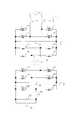
종래의 전기 자동차용 단방향 충전기의 회로구조는 크게 입력단 PFC 컨버터(100)와 풀브리지 스위칭(Full-bridge Switching) 수단(200), 출력단 LC필터(21, 22)로 구성되며, 그 상세구조를 살펴보면, 도 1과 같다. 도 1의 단상 교류 전원(1)은 입력단 PFC용 인덕터(2, 3)와 입력단 PFC용 FET(4, 5, 6, 7)및 입력단 PFC용 출력필터 콘덴서(8)로 구성된 양방향 입력단 PFC(Power Factor Correction, 역률 보상) 컨버터(100)에 의해서 가변 직류 전압의 형태로 전압전류의 역률이 1로 유지된다. 또한, 이 가변 직류 전압은 DC/DC 1차측 FET(9, 10, 11, 12)와 DC/DC용 고주파 변압기(13), DC/DC용 정류다이오드(24, 25, 26, 27) 및 출력단 LC필터(21, 22)로 구성된 풀브리지 스위칭 수단(200)에 의해서 절연된 가변전압, 가변전류의 형태로 배터리(23)를 충전하게 된다. 여기서, 풀브리지 스위칭 수단(200)는 영전압 스위칭을 통해 고효율을 유지하게 되는데, 그러한 영전압 스위칭은 위상천이 제어(Phase Shift Control)을 통한 소프트웨어와 하드웨어의 기법과 회로를 구성하는 DC/DC용 고주파변압기(13)의 누설인덕턴스와 권선 커패시턴스, DC/DC용 정류다이오드(24, 25, 26, 27)의 등가 커패시턴스 등의 요소가 결합된 공진조건에 의해 달성되게 된다. 즉, 고효율을 유지하기 위한 조건을 만족시키도록 여러 가지 측면에서 조율을 해야만 한다는 것이다.The circuit structure of a conventional unidirectional charger for an electric vehicle is largely composed of an input
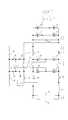
종래의 전기 자동차용 양방향 충전기의 회로구조는 크게 입력단 PFC 컨버터(100)와 양방향 DC/DC 컨버터(300), 벅 부스트 컨버터(400)로 구성되며, 그 상세구조를 살펴보면, 도 2와 같다. 도 2의 단상 교류 전원(1)은 입력단 PFC용 인덕터(2, 3)와 입력단 PFC용 FET(4, 5, 6, 7)및 입력단 PFC용 출력필터 콘덴서(8)로 구성된 양방향 입력단 PFC 컨버터(100)에 의해서 가변 직류 전압의 형태로 전압전류의 역률이 1로 유지된다. 또한, 이 가변 직류 전압은 DC/DC 1차측 FET(9, 10, 11, 12)와 DC/DC용 고주파 변압기(13), DC/DC 2차측 FET(14, 15, 16, 17) 및 DC/DC용 출력필터 콘덴서(18)로 구성된 양방향 DC/DC 컨버터(300)에 의해서 절연된 가변전압, 가변전류의 형태로 출력필터 콘덴서의 전압을 충전 또는 방전하게 된다. 그리고, 벅 부스트(Buck Boost) FET(19, 20), 출력단 LC필터(21, 22)로 구성된 벅 부스트 컨버터(400, 강압 승압 컨버터, Buck Boost Converter)는 충전모드일 때는 벅{Buck, 강압(전압을 낮춤)} 컨버터로 동작하여 절연된 가변전압, 가변전류의 형태로 배터리(23)를 충전하며, 방전모드일 때는 부스트{Boost,승압(전압을 높임)} 컨버터로 동작하여 배터리(23)를 방전시킨다.The circuit structure of the conventional bidirectional charger for an electric vehicle is largely composed of an input
충전 모드에 대해 좀더 구체적으로 설명하면, 도 3은 종래의 양방향 충전기가 충전모드일 때 동작을 설명하기 위한 회로 구성도이다. 도 3에 표시한 것처럼, 충전모드일 때 입력단 PFC 컨버터(100)에서 입력단 PFC용 FET(4, 5, 6, 7)중에서 5번과 7번 FET는 연속동작을 하고 4번과 6번 FET는 바디 다이오드(Body Diode)만 동작한다. 또한, 양방향 DC/DC 컨버터(300)에서 DC/DC 2차측 FET(14, 15, 16, 17)도 바디 다이오드만 동작한다. 그리고, 벅 부스트 컨버터(400)에서 벅 부스트 FET(19, 20)중에서 19번 FET는 연속동작을 하고 20번 FET는 바디 다이오드만 동작한다. 이는 도 1의 종래의 전기 자동차용 단방향 충전기의 회로구조와 유사한 형태가 된다.Referring to the charging mode in more detail, Figure 3 is a circuit diagram for explaining the operation when the conventional two-way charger in the charging mode. As shown in FIG. 3, in the charging mode, the
종래의 양방향 충전기가 충전모드일 때 동작을 도 3을 참조하여 좀더 구체적으로 설명한다. 단상 교류 전원(1)은 입력단 PFC용 인덕터(2, 3)와 입력단 PFC용 FET(5, 7)와 입력단 PFC용 FET(4, 6)의 바디 다이오드 및 입력단 PFC용 출력필터 콘덴서(8)로 구성된 양방향 입력단 PFC 컨버터(100)에 의해서 가변 직류 전압의 형태로 전압전류의 역률이 1로 유지된다. 또한, 이 가변 직류 전압은 DC/DC 1차측 FET(9, 10, 11, 12)와 DC/DC용 고주파 변압기(13), DC/DC 2차측 FET(14, 15, 16, 17)의 바디 다이오드 및 DC/DC용 출력필터 콘덴서(18)로 구성된 양방향 DC/DC 컨버터(300)에 의해서 절연된 가변전압, 가변전류의 형태로 출력필터 콘덴서(18)의 전압을 충전하게 된다. 그리고, 출력필터 콘덴서(18)에 충전된 전압은 벅 FET(19), 부스트 FET(20)의 바디 다이오드, 출력단 LC필터(21, 22)로 구성된 벅 부스트 컨버터(400)에 의해서 벅 컨버터로 동작하여 절연된 가변전압, 가변전류의 형태로 배터리(23)를 충전하게 된다.The operation of the conventional bidirectional charger in the charging mode will be described in more detail with reference to FIG. 3. The single-phase
도 4는 종래의 양방향 충전기가 방전모드일 때 동작을 설명하기 위한 회로 구성도이다. 도 4에 표시한 것처럼, 방전모드일 때 양방향 DC/DC 컨버터(300)에서 DC/DC 1차측 FET(9, 10, 11, 12)의 바디 다이오드만 동작한다. 그리고, 벅 부스트 컨버터(400)에서 벅 부스트 FET(19, 20)중에서 20번 부스트 FET는 연속동작을 하고 19번 벅 FET는 바디 다이오드만 동작한다. 이는 도 1의 종래의 전기 자동차용 단방향 충전기의 회로구조와 좌우가 대칭인 형태가 된다.4 is a circuit diagram illustrating an operation when a conventional bidirectional charger is in a discharge mode. As shown in FIG. 4, only the body diodes of the DC / DC
종래의 양방향 충전기가 방전모드일 때 동작은 다음과 같다. 도 4의 배터리(23)에 충전되었던 전압은 벅 FET(19)의 바디 다이오드, 부스트 FET(20), 출력단 LC필터(21, 22)로 구성된 벅 부스트 컨버터(400)에 의해서 부스트 컨버터로 동작하여 절연된 가변전압, 가변전류의 형태로 배터리(23)의 전력을 DC/DC용 출력필터 콘덴서(18)로 방전하게 된다. DC/DC용 출력필터 콘덴서(18)의 전압은 DC/DC 2차측 FET(14, 15, 16, 17)와 DC/DC용 고주파 변압기(13), DC/DC 1차측 FET(9, 10, 11, 12)의 바디 다이오드 및 입력단 PFC용 출력필터 콘덴서(8)로 구성된 양방향 DC/DC 컨버터(300)에 의해서 절연된 가변전압의 형태로 입력단 PFC용 출력필터 콘덴서(8)의 전압을 충전하게 된다. 입력단 PFC용 출력필터 콘덴서(8)의 전압은 입력단 PFC용 FET(4, 5, 6, 7)와 입력단 PFC용 인덕터(2, 3)로 구성된 양방향 입력단 PFC 컨버터(100)에 의해서 가변 직류 전압의 형태로 전압전류의 역률이 1로 유지하면서 단상 교류 전원(1)으로 방전하게 된다.When the conventional bidirectional charger is in the discharge mode, the operation is as follows. The voltage charged in the
종래의 양방향 충전기는 크게 입력단 PFC 컨버터(100)와 양방향 DC/DC 컨버터(300), 벅 부스트 컨버터(400)로 구성되는데, 이는 많은 수의 전력용 반도체를 필요로 하므로, 이를 구동하기 위한 절연전원의 숫자도 그 만큼 늘어나게 된다. 또한, 별도의 제어 구동 신호가 필요 하므로 시스템의 복잡성을 가중 시킨다. 그리고, 양방향 DC/DC 컨버터(300)의 장점은 고효율이어야 하는데, 충전모드일 때와 방전모드일 때 FET의 바디 다이오드를 겸용으로 사용할 수 있다는 장점만 있을 뿐, 실제 고효율을 유지하기 위한 공진요소를 조율하기가 어렵고, 고효율의 다이오드를 사용할 때에 비해서 FET의 바디 다이오드는 손실이 크다는 단점을 가지고 있다. 또한 전기 자동차의 배터리(23)가 다소 방전되었을 때, 양방향 충전기가 방전모드로 동작하려면 변압기의 턴비를 교체(변화시킴), 또는 별도의 부가회로가 필요하게 되어 더욱 더 시스템은 복잡하게 된다.Conventional bidirectional chargers are largely composed of an input
본 발명은 이와 같은 문제점을 해결하기 위해 창출된 것으로, 본 발명의 목적은 양방향 충전기의 전력용 반도체 스위치의 숫자를 줄여, 이를 구동하기 위한 절연전원의 숫자도 그 만큼 줄어들게 하는 것이다. 또한, 별도의 제어 구동 신호도 줄어들게 하므로 양방향 충전기 제어시스템을 간략하게 함에 있다.The present invention has been made to solve the above problems, and an object of the present invention is to reduce the number of power semiconductor switches for the bidirectional charger, thereby reducing the number of the insulation power for driving the same. In addition, since the separate control drive signal is also reduced to simplify the two-way charger control system.
본 발명의 다른 목적은, 단방향 영전압 스위칭 DC/DC 컨버터를 원래의 형태를 그대로 사용하여 충전 및 방전 모드에서 모두 양방향 충전 시스템이 고효율을 유지하도록 하는 것이다.Another object of the present invention is to use the unidirectional zero voltage switching DC / DC converter in its original form as it is so that the bidirectional charging system maintains high efficiency in both charge and discharge modes.
본 발명의 또 다른 목적은, 단방향 영전압 스위칭 DC/DC 컨버터의 운영방법을 통해 불필요한 벅 부스트 컨버터(400)를 삭제하도록 하여 양방향 충전 시스템의 소형 경량화를 이루는 것이다.Still another object of the present invention is to eliminate unnecessary
상기 목적을 달성하기 위한 본 발명에서 제안하는 양방향 충전 시스템은, 교류 전원과 배터리 사이에서 충전 및 방전이 선택적으로 실행되기 위하여, 교류 입력 전압을 직류 전압으로 변환함과 동시에 전압의 역률을 보상하는 PFC 컨버터, 입력된 직류 전압을 영전압 스위칭하여 교류 전압으로 변환시키는 풀브리지 스위칭 수단, 상기 풀브리지 스위칭 수단에서 출력된 전압을 받아서 교류 전압을 출력하는 고주파 변압기, 상기 고주파 변압기에서 출력된 전압을 정류하는 정류 수단 및 상기 교류 전원과 상기 배터리 사이에서 충전과 방전을 전환시키기 위해 상기 PFC 컨버터와 상기 풀브리지 스위칭 수단 사이의 전류 방향을 변경시키도록 상기 PFC 컨버터와 상기 풀브리지 스위칭 수단에 접속된 릴레이 수단으로 이루어진 것을 특징으로 한다.In order to achieve the above object, the bidirectional charging system proposed by the present invention includes a PFC that converts an AC input voltage into a DC voltage and compensates for the power factor of the voltage in order to selectively perform charging and discharging between an AC power supply and a battery. Converter, full bridge switching means for converting the input DC voltage to zero voltage switching to an AC voltage, a high frequency transformer receiving the voltage output from the full bridge switching means and outputting an AC voltage, rectifying the voltage output from the high frequency transformer Rectification means and relay means connected to the PFC converter and the full bridge switching means to change the current direction between the PFC converter and the full bridge switching means to switch charging and discharging between the AC power source and the battery. Characterized in that made.
상기 릴레이 수단은 상기 릴레이 수단은 충전 시에 상기 PFC 컨버터와 상기 풀브리지 스위칭 수단 사이에 전류 흐름 경로를 형성시키고, 방전 시에 상기 PFC 컨버터와 상기 풀브리지 스위칭 수단 사이를 차단하는 충전 입력단 릴레이, 충전 시에 상기 배터리와 상기 정류 수단을 접속시키고, 방전 시에 상기 상기 배터리와 상기 정류 수단을 차단시키는 충전 출력단 릴레이, 방전 시에 상기 배터리와 상기 풀브리지 스위칭 수단을 접속시키는 방전 입력단 릴레이 및 방전 시에 상기 정류 수단과 상기 PFC 컨버터를 접속시키는 방전 출력단 릴레이로 구성된다.The relay means is a charging input stage relay for the relay means to form a current flow path between the PFC converter and the full bridge switching means during charging, and to disconnect between the PFC converter and the full bridge switching means during discharge, charging A charge output stage relay which connects the battery and the rectifying means at a time, disconnects the battery and the rectifier means at a discharge, a discharge input stage relay which connects the battery and the full bridge switching means at a time of discharge, and a discharge time. And a discharge output stage relay connecting the rectifying means and the PFC converter.
본 발명에 따른 양방향 충전 시스템은, 단방향으로 사용되던 풀브리지 스위칭 수단의 원래의 형태를 그대로 사용하기 때문에 일반적인 양방향 충전기에 비해 FET 등의 전력용 반도체 스위치 필요 숫자가 적어지고, 충전 및 방전 모드에서 모두 고효율을 유지할 수 있으며, 제어요소가 줄어, 전력밀도 향상 및 소형 경량화를 이룰 수 있는 효과가 있다.Since the bidirectional charging system according to the present invention uses the original form of the full bridge switching means used in one direction as it is, the number of power semiconductor switches such as FETs is smaller than that of a general bidirectional charger, and both in the charging and discharging modes. High efficiency can be maintained, and control elements are reduced, resulting in improved power density and compact weight.
도 1은 종래의 단방향 충전기의 구조를 설명하기 위한 회로도,
도 2는 종래의 양방향 충전기의 구조를 설명하기 위한 회로도,
도 3은 종래의 양방향 충전기가 충전모드일 때 동작을 설명하기 위한 회로 구성도,
도 4는 종래의 양방향 충전기가 방전모드일 때 동작을 설명하기 위한 회로 구성도,
도 5는 본 발명에서 제안하는 양방향 충전기의 구조를 설명하기 위한 회로도,
도 6은 본 발명에서 제안하는 양방향 충전기가 충전모드일 때 동작을 설명하기 위한 회로 구성도,
도 7은 본 발명에서 제안하는 양방향 충전기가 방전모드일 때 동작을 설명하기 위한 회로 구성도이다.1 is a circuit diagram for explaining the structure of a conventional unidirectional charger;
2 is a circuit diagram illustrating a structure of a conventional bidirectional charger;
3 is a circuit diagram illustrating an operation when a conventional bidirectional charger is in a charging mode;
4 is a circuit diagram illustrating an operation when a conventional bidirectional charger is in a discharge mode;
5 is a circuit diagram for explaining the structure of the bidirectional charger proposed in the present invention;
6 is a circuit diagram illustrating an operation when a bidirectional charger proposed in the present invention is in a charging mode.
7 is a circuit diagram illustrating an operation when the bidirectional charger proposed in the present invention is in the discharge mode.
이하, 본 발명의 바람직한 실시 예를 첨부된 예시도면에 의거 상세히 설명하면 다음과 같다.Hereinafter, preferred embodiments of the present invention will be described in detail with reference to the accompanying drawings.
도 5 내지 도 7에 도시된 바와 같이, 본 발명의 양방향 충전 시스템은, 교류 전원(1)과 배터리(23) 사이에서 충전 및 방전이 선택적으로 실행되기 위하여, 교류 입력 전압을 직류 전압으로 변환함과 동시에 전압의 역률을 보상하는 PFC(역률 보상) 컨버터(100), 입력된 직류 전압을 영전압 스위칭을 통해 고효율인 파형을 가진 직류 전압으로 변환시키는 풀브리지 스위칭 수단(200), 상기 풀브리지 스위칭 수단(200)에서 출력된 전압을 받아서 교류 전압을 출력하는 고주파 변압기(13), 상기 고주파 변압기에서 출력된 전압을 정류하는 정류 수단(24, 25, 26, 27) 및 상기 교류 전원(1)과 상기 배터리(23) 사이에서 충전과 방전을 전환시키기 위해 상기 PFC 컨버터(100)와 상기 풀브리지 스위칭 수단(200)에 접속된 릴레이 수단으로 이루어진 것을 특징으로 한다.As shown in FIGS. 5 to 7, the bidirectional charging system of the present invention converts an AC input voltage into a DC voltage in order to selectively perform charging and discharging between the
상기 릴레이 수단은 충전 시에 상기 PFC 컨버터(100)와 상기 풀브리지 스위칭 수단(200) 사이에 전류 흐름 경로를 형성시키고, 방전 시에 상기 PFC 컨버터(100)와 상기 풀브리지 스위칭 수단(200) 사이를 차단하는 충전 입력단 릴레이(31, 32), 충전 시에 상기 배터리(23)와 상기 정류 수단(24, 25, 26, 27)을 접속시키고, 방전 시에 상기 배터리(23)와 상기 정류 수단(24, 25, 26, 27)을 차단시키는 충전 출력단 릴레이(33, 34), 방전 시에 상기 배터리(23)와 상기 풀브리지 스위칭 수단(200)를 접속시키는 방전 입력단 릴레이(35, 36), 방전 시에 상기 정류 수단(24, 25, 26, 27)과 상기 PFC 컨버터(100)를 접속시키는 방전 출력단 릴레이(37, 38)로 구성된다.The relay means forms a current flow path between the
도 5에서, 키 입력 수단(40)은 사용자가 동작 명령을 입력하는 버튼, 마우스 혹은 무선 입력 장치 등을 의미한다. 상기 제어 수단(42)은 전기 자동차 배터리의 충방전 동작을 제어하는 마이크로프로세서를 의미한다.In FIG. 5, the key input means 40 refers to a button, a mouse or a wireless input device that a user inputs an operation command. The control means 42 means a microprocessor for controlling the charging and discharging operation of the electric vehicle battery.
좀더 구체적으로 설명하면, 본 발명의 양방향 충전기의 구조는 도 5에 도시된 바와 같이, 크게 입력단 PFC 컨버터(100)와 풀브리지 스위칭 수단(200), 출력단 LC필터(21, 22), 충전입력단 릴레이(31, 32), 충전출력단 릴레이(33, 34), 방전입력단 릴레이(35, 36), 방전출력단 릴레이(37, 38)로 구성된다. 기본적인 형태는 종래의 전기 자동차용 단방향 충전기의 회로구조를 유지하는 것이며, 여기에, 충전모드일 때는 충전입력단 릴레이(31, 32)와 충전출력단 릴레이(33, 34)를 온하고, 방전입력단 릴레이(35, 36)와 방전출력단 릴레이(37, 38)를 오프하는 것이다. 방전모드일 때는 방전입력단 릴레이(35, 36)와 방전출력단 릴레이(37, 38)를 온하고, 충전입력단 릴레이(31, 32)와 충전출력단 릴레이(33, 34)를 오프하는 것이다. 즉, 기본적인 형태는 종래의 전기 자동차용 단방향 충전기의 회로구조를 유지하면서 릴레이의 구동여부에 의해 충전모드와 방전모드가 구분된다.More specifically, as shown in FIG. 5, the bidirectional charger of the present invention has a large input
도 6은 본 발명에서 제안하는 양방향 충전기가 충전모드일 때 동작을 설명하기 위한 회로 구성도이다. 충전모드일 때는, 사용자가 키 입력 수단(40)에 충전 명령을 입력한다. 그러면 상기 키 입력 수단(40)으로부터 제어 수단(42)로 충전 명령이 입력된다. 이어서, 상기 제어 수단(42)으로부터 구동코일(L1)로 제어 신호가 입력된다. 그러면 상기 구동 코일(L1)로부터 상기 충전 입력단 릴레이(31, 32)와 충전 출력단 릴레이(33, 34)에 구동 신호가 인가되어 상기 충전 릴레이(31, 32, 33, 34)들이 온된다.6 is a circuit diagram illustrating an operation when the bidirectional charger proposed in the present invention is in the charging mode. In the charging mode, the user inputs a charging command to the key input means 40. The charging command is then input from the key input means 40 to the control means 42. Subsequently, a control signal is input from the control means 42 to the drive coil L1. Then, a driving signal is applied from the driving coil L1 to the charging input terminal relays 31 and 32 and the charging output terminal relays 33 and 34 to turn on the charging relays 31, 32, 33, and 34.
동시에 상기 제어 수단(42)으로부터 구동코일(L2)로 턴오프 제어 신호가 입력된다. 그러면 상기 구동 코일(L2)로부터 상기 방전 입력단 릴레이(35, 36)와 상기 방전 출력단 릴레이(37, 38)에 정지 신호가 인가되어 상기 방전 릴레이들(35, 36, 37, 38)이 오프된다.At the same time, the turn-off control signal is input from the control means 42 to the drive coil L2. Then, the stop signal is applied to the discharge input relays 35 and 36 and the discharge output relays 37 and 38 from the driving coil L2 to turn off the discharge relays 35, 36, 37 and 38.
다음에, 도 6의 단상 교류 전원(1)은 입력단 PFC용 인덕터(2, 3)와 입력단 PFC용 FET(4, 5, 6, 7)및 입력단 PFC용 출력필터 콘덴서(8)로 구성된 양방향 입력단 PFC(Power Factor Correction, 역률 보상) 컨버터(100)에 의해서 가변 직류 전압의 형태로 전압전류의 역률이 1로 유지된다. 이 가변 직류 전압은 충전입력단 릴레이(31, 32)를 통해 풀브리지 스위칭 수단(200)로 공급된다. 또한, 이 가변 직류 전압은 DC/DC 1차측 FET(9, 10, 11, 12)와 DC/DC용 고주파 변압기(13), DC/DC용 정류다이오드(24, 25, 26, 27)로 구성된 풀브리지 스위칭 수단(200)에 의해서 충전출력단 릴레이(33, 34)를 통해 출력단 LC필터(21, 22)로 전달되며, 이는 절연된 가변전압, 가변전류의 형태로 배터리(23)를 충전하게 된다.Next, the single-phase
DC/DC용 정류다이오드(24, 25, 26, 27)은 충전 시와 방전 시에 모두 상기 고주파 변압기에서 출력된 전압을 정류하는 정류 수단을 구성한다.The rectifying
도 7은 본 발명에서 제안하는 양방향 충전기가 방전모드일 때 동작을 설명하기 위한 회로 구성도이다. 방전모드일 때는 사용자가 키 입력 수단(40)에 방전 명령을 입력한다. 그러면 상기 키 입력 수단(40)으로부터 제어 수단(42)으로 방전 명령이 전달된다. 이어서, 상기 제어 수단(42)으로부터 구동코일(L2)로 제어 신호가 입력된다. 그러면 상기 구동 코일(L2)로부터 상기 방전 입력단 릴레이(35, 36)와 충전 출력단 릴레이(37, 38)에 구동 신호가 인가되어 상기 방전 릴레이(35, 36, 37, 38)들이 온된다.7 is a circuit diagram illustrating an operation when the bidirectional charger proposed in the present invention is in the discharge mode. In the discharge mode, the user inputs a discharge command to the key input means 40. The discharge command is then transmitted from the key input means 40 to the control means 42. Subsequently, a control signal is input from the control means 42 to the drive coil L2. Then, a driving signal is applied from the driving coil L2 to the discharge input terminal relays 35 and 36 and the charge output terminal relays 37 and 38 to turn on the discharge relays 35, 36, 37 and 38.
동시에 상기 제어 수단(42)으로부터 구동코일(L1)로 턴오프 제어 신호가 입력된다. 그러면 상기 구동 코일(L1)로부터 상기 충전 입력단 릴레이(31, 32)와 상기 충전 출력단 릴레이(33, 34)에 정지 신호가 인가되어 상기 충전 릴레이들(31, 32, 33, 34)이 오프된다.At the same time, the turn-off control signal is input from the control means 42 to the drive coil L1. Then, a stop signal is applied to the charging input terminal relays 31 and 32 and the charging output terminal relays 33 and 34 from the driving coil L1 to turn off the charging relays 31, 32, 33, 34.
그러면, 도 7의 배터리(23)에 충전되었던 전압은 방전입력단 릴레이(35, 36)를 통해 풀브리지 스위칭 수단(200)로 공급된다. 또한, 이 배터리(23) 직류 전압은 DC/DC 1차측 FET(9, 10, 11, 12)와 DC/DC용 고주파 변압기(13), DC/DC용 정류다이오드(24, 25, 26, 27)로 구성된 풀브리지 스위칭 수단(200)에 의해서 방전출력단 릴레이(37, 38)를 통해 절연된 가변전압의 형태로 입력단 PFC용 출력필터 콘덴서(8)로 전달된다. 그러면 상기 PFC용 출력필터 콘덴서(8)가 충전된다. 다음에 상기 입력단 PFC용 출력필터 콘덴서(8)의 전압은 입력단 PFC용 FET(4, 5, 6, 7)와 입력단 PFC용 인덕터(2, 3)로 구성된 양방향 입력단 PFC 컨버터(100)에 의해서 가변 직류 전압의 형태로 전압전류의 역률이 1로 유지하면서 단상 교류 전원(1)으로 방전한다.Then, the voltage charged in the
이 경우, 상기 릴레이 수단(31, 32, 33, 34, 35, 36, 37, 38)에 의해 절연(Insulation)형과 비절연(Non-insulation)형 회로의 전기적인 선택이 용이하게 실현된다.In this case, the electrical selection between the insulation type and the non-insulation type circuit is easily realized by the relay means 31, 32, 33, 34, 35, 36, 37, 38.
이상의 설명에서와 같이, 본 발명에 따른 양방향 충전 시스템은, 단방향 영전압 스위칭 DC/DC 컨버터를 원래의 형태를 그대로 사용하기 때문에 일반적인 양방향 충전기에 비해 FET 등의 전력용 반도체 스위치 필요 숫자가 적어지고, 충전 및 방전 모드에서 모두 고효율을 유지할 수 있으며, 제어요소가 줄어, 전력밀도 향상 및 소형 경량화를 이룰 수 있는 효과가 있다. 따라서 본 발명은 양방향 충전 시스템의 성능을 향상시키고, 단가를 격감시키며, 시스템의 안정성을 도모하여 전기 자동차 산업에 이바지할 수 있다.As described above, in the bidirectional charging system according to the present invention, since the unidirectional zero voltage switching DC / DC converter uses the original form as it is, the number of power semiconductor switches such as FETs is smaller than that of a general bidirectional charger. High efficiency can be maintained in both charging and discharging modes, reducing control elements, improving power density, and reducing weight. Therefore, the present invention can contribute to the electric vehicle industry by improving the performance of the bidirectional charging system, reducing the unit cost, and improving the stability of the system.
1 : 단상 교류 전원 2, 3 : 입력단 PFC용 인덕터
4, 5, 6, 7 : 입력단 PFC용 FET 8 : 입력단 PFC용 출력필터 콘덴서
9, 10, 11, 12 : DC/DC 1차측 FET 13 : DC/DC용 고주파 변압기
14, 15, 16, 17 : DC/DC 2차측 FET 18 : DC/DC용 출력필터 콘덴서
19, 20 : 벅 부스트 FET 21, 22 : 출력단 LC필터
23 : 배터리
24, 25, 26, 27 : DC/DC용 정류다이오드
31, 32 : 충전입력단 릴레이 33, 34 : 충전출력단 릴레이
35, 36 : 방전입력단 릴레이 37, 38 : 방전출력단 릴레이
40 : 키 입력 수단 42 : 제어 수단
100 : PFC 컨버터 200 : 풀브리지 스위칭 수단
300 : 양방향 DC/DC 컨버터
400 : 벅 부스트 컨버터(Buck Boost Converter)1: single-phase
4, 5, 6, 7: Input stage PFC FET 8: Input stage PFC output filter capacitor
9, 10, 11, 12: DC / DC primary side FET 13: High frequency transformer for DC / DC
14, 15, 16, 17: DC / DC secondary side FET 18: DC / DC output filter capacitor
19, 20:
23: battery
24, 25, 26, 27: rectifier diode for DC / DC
31, 32: charging
35, 36:
40: key input means 42: control means
100: PFC converter 200: full bridge switching means
300: Bidirectional DC / DC Converter
400: Buck Boost Converter
Claims (6)
Translated fromKorean교류 입력 전압을 직류 전압으로 변환함과 동시에 전압의 역률을 보상하는 PFC 컨버터,
입력된 직류 전압을 영전압 스위칭하여 교류 전압으로 변환시키는 풀브리지 스위칭 수단,
상기 풀브리지 스위칭 수단에서 출력된 전압을 받아서 교류 전압을 출력하는 고주파 변압기,
상기 고주파 변압기에서 출력된 전압을 정류하는 정류 수단 및
상기 교류 전원과 상기 배터리 사이에서 충전과 방전을 전환시키기 위해 상기 PFC 컨버터와 상기 풀브리지 스위칭 수단 사이의 전류 방향을 변경시키도록 상기 PFC 컨버터와 상기 풀브리지 스위칭 수단에 접속된 릴레이 수단으로 이루어진 것을 특징으로 하는 양방향 충전 시스템.In order to selectively charge and discharge between the AC power source and the battery,
PFC converter that converts AC input voltage to DC voltage and at the same time compensates the power factor of the voltage,
Full bridge switching means for converting the input DC voltage to zero voltage switching to an AC voltage,
A high frequency transformer receiving an output voltage from the full bridge switching means and outputting an alternating voltage;
Rectifying means for rectifying the voltage output from the high frequency transformer;
A relay means connected to the PFC converter and the full bridge switching means to change the current direction between the PFC converter and the full bridge switching means to switch charging and discharging between the AC power source and the battery. Bidirectional charging system.
충전 시에 상기 PFC 컨버터와 상기 풀브리지 스위칭 수단 사이에 전류 흐름 경로를 형성시키고, 방전 시에 상기 PFC 컨버터와 상기 풀브리지 스위칭 수단 사이를 차단하는 충전 입력단 릴레이,
충전 시에 상기 배터리와 상기 정류 수단을 접속시키고, 방전 시에 상기 상기 배터리와 상기 정류 수단을 차단시키는 충전 출력단 릴레이,
방전 시에 상기 배터리와 상기 풀브리지 스위칭 수단을 접속시키는 방전 입력단 릴레이,
방전 시에 상기 정류 수단과 상기 PFC 컨버터를 접속시키는 방전 출력단 릴레이로 구성된 것을 특징으로 하는 양방향 충전 시스템.
The method of claim 1 wherein the relay means
A charging input stage relay which forms a current flow path between the PFC converter and the full bridge switching means during charging and cuts off between the PFC converter and the full bridge switching means when discharging,
A charging output stage relay which connects the battery and the rectifying means at the time of charging and shuts off the battery and the rectifying means at the time of discharge;
A discharge input stage relay which connects the battery and the full bridge switching means during discharge;
And a discharge output stage relay connecting the rectifying means and the PFC converter during discharge.
Priority Applications (1)
| Application Number | Priority Date | Filing Date | Title |
|---|---|---|---|
| KR1020100014176AKR101191137B1 (en) | 2010-02-17 | 2010-02-17 | Bi-Directional Charging System |
Applications Claiming Priority (1)
| Application Number | Priority Date | Filing Date | Title |
|---|---|---|---|
| KR1020100014176AKR101191137B1 (en) | 2010-02-17 | 2010-02-17 | Bi-Directional Charging System |
Publications (2)
| Publication Number | Publication Date |
|---|---|
| KR20110094634A KR20110094634A (en) | 2011-08-24 |
| KR101191137B1true KR101191137B1 (en) | 2012-11-15 |
Family
ID=44930610
Family Applications (1)
| Application Number | Title | Priority Date | Filing Date |
|---|---|---|---|
| KR1020100014176AActiveKR101191137B1 (en) | 2010-02-17 | 2010-02-17 | Bi-Directional Charging System |
Country Status (1)
| Country | Link |
|---|---|
| KR (1) | KR101191137B1 (en) |
Cited By (2)
| Publication number | Priority date | Publication date | Assignee | Title |
|---|---|---|---|---|
| KR20160140299A (en)* | 2015-05-29 | 2016-12-07 | 숭실대학교산학협력단 | A charger with battery diagnosis function and control method thereof |
| US9958509B2 (en) | 2015-05-29 | 2018-05-01 | Foundation Of Soongsil University-Industry Cooperation | Charger having battery diagnosis function and method of driving the same |
Families Citing this family (14)
| Publication number | Priority date | Publication date | Assignee | Title |
|---|---|---|---|---|
| WO2013137501A1 (en)* | 2012-03-14 | 2013-09-19 | (주)시그넷시스템 | Charging station |
| KR20140054796A (en) | 2012-10-29 | 2014-05-09 | 삼성전기주식회사 | Power supplying apparatus and power supplying apparatus of electric vechicle |
| KR101509910B1 (en) | 2013-08-26 | 2015-04-06 | 현대자동차주식회사 | Charging control method for plug-in hybrid electric vehicle and electric vehicle |
| KR101583881B1 (en) | 2013-12-10 | 2016-01-21 | 현대자동차주식회사 | Apparatus and Method for controlling charge for battery |
| KR101587488B1 (en)* | 2014-03-26 | 2016-01-21 | (주)이이시스 | High efficiency battery charge/discharge system and method in grid-tied system |
| KR101836577B1 (en) | 2015-11-30 | 2018-04-20 | 현대자동차주식회사 | Charging control method and system of high voltage battery for vehicle |
| KR101887785B1 (en)* | 2016-12-02 | 2018-08-13 | 현대자동차주식회사 | Charging system and controlling method therefor |
| WO2019046939A1 (en)* | 2017-09-05 | 2019-03-14 | The Governing Council Of The University Of Toronto | Electric vehicle power-hub and operating modes thereof |
| KR102655686B1 (en)* | 2019-09-02 | 2024-04-09 | 현대자동차주식회사 | Battery integrated antenna |
| CN110888052A (en)* | 2019-12-01 | 2020-03-17 | 国网辽宁省电力有限公司电力科学研究院 | High-voltage switch cabinet partial discharge on-line monitoring system and method based on ultrahigh frequency technology |
| KR102338378B1 (en)* | 2019-12-27 | 2021-12-10 | 현대오토에버 주식회사 | Battery charging system of vehicle |
| WO2021182648A1 (en)* | 2020-03-09 | 2021-09-16 | (주)에이프로 | Zero voltage discharge circuit device |
| KR102315046B1 (en)* | 2020-09-01 | 2021-10-20 | (주)에이프로 | Apparatus of Zerovoltage Discharge |
| KR102790854B1 (en)* | 2023-11-27 | 2025-04-07 | 주식회사 미래이앤아이 | Bi-Directional Charging System |
Citations (2)
| Publication number | Priority date | Publication date | Assignee | Title |
|---|---|---|---|---|
| JP2000262072A (en) | 1999-03-11 | 2000-09-22 | Chiyoda:Kk | Power regeneration type charge / discharge device |
| JP2009290919A (en) | 2008-05-27 | 2009-12-10 | Panasonic Corp | Power converter |
- 2010
- 2010-02-17KRKR1020100014176Apatent/KR101191137B1/enactiveActive
Patent Citations (2)
| Publication number | Priority date | Publication date | Assignee | Title |
|---|---|---|---|---|
| JP2000262072A (en) | 1999-03-11 | 2000-09-22 | Chiyoda:Kk | Power regeneration type charge / discharge device |
| JP2009290919A (en) | 2008-05-27 | 2009-12-10 | Panasonic Corp | Power converter |
Cited By (3)
| Publication number | Priority date | Publication date | Assignee | Title |
|---|---|---|---|---|
| KR20160140299A (en)* | 2015-05-29 | 2016-12-07 | 숭실대학교산학협력단 | A charger with battery diagnosis function and control method thereof |
| KR101703122B1 (en)* | 2015-05-29 | 2017-02-06 | 숭실대학교산학협력단 | A charger with battery diagnosis function and control method thereof |
| US9958509B2 (en) | 2015-05-29 | 2018-05-01 | Foundation Of Soongsil University-Industry Cooperation | Charger having battery diagnosis function and method of driving the same |
Also Published As
| Publication number | Publication date |
|---|---|
| KR20110094634A (en) | 2011-08-24 |
Similar Documents
| Publication | Publication Date | Title |
|---|---|---|
| KR101191137B1 (en) | Bi-Directional Charging System | |
| JP7161548B2 (en) | DCDC converters, onboard chargers and electric vehicles | |
| JP4910078B1 (en) | DC / DC converter and AC / DC converter | |
| JP6292497B2 (en) | Power converter, power conditioner | |
| US20160181925A1 (en) | Bidirectional dc-dc converter | |
| JP5396251B2 (en) | DC-DC bidirectional converter circuit | |
| WO2007060998A1 (en) | Ac link bidirectional dc-dc converter, hybrid power supply system using the same, and hybrid vehicle | |
| KR101714593B1 (en) | Bi-directional ev chartger for v2g and v2h application | |
| KR20160007852A (en) | A Pulse Width Modulation Resonance Converter and Charger for Vehicle Using the Same | |
| JP2010063215A (en) | Bidirectional dc-dc converter and method of controlling the same | |
| CN103187876A (en) | DC/DC circuit for UPS | |
| KR102730545B1 (en) | Electric power conversion system and control method therefor | |
| JP2015159711A (en) | Switching power supply and power converter | |
| KR101734641B1 (en) | Charging device of vehicle | |
| KR102500741B1 (en) | Combined power conversion circuit of OBC and LDC for electric vehicles | |
| US20240186908A1 (en) | Power supply apparatus, three-phase transformer circuit, and charging pile | |
| CN112350389A (en) | Integrated control circuit of vehicle-mounted charger and DC/DC | |
| Salem et al. | A review of an inductive power transfer system for EV battery charger | |
| CN110417268B (en) | On-board chargers and electric vehicles | |
| KR20200062835A (en) | Isolated bi-directional DC-DC converter charger for electric vehicles | |
| KR101203882B1 (en) | Insulated Bi-Directional Charging System | |
| JP5412515B2 (en) | Power supply | |
| KR101558770B1 (en) | Charging device of vehicle | |
| KR102273763B1 (en) | LLC resonant converter | |
| JP5587382B2 (en) | Bidirectional DC-DC converter |
Legal Events
| Date | Code | Title | Description |
|---|---|---|---|
| A201 | Request for examination | ||
| PA0109 | Patent application | St.27 status event code:A-0-1-A10-A12-nap-PA0109 | |
| PA0201 | Request for examination | St.27 status event code:A-1-2-D10-D11-exm-PA0201 | |
| PG1501 | Laying open of application | St.27 status event code:A-1-1-Q10-Q12-nap-PG1501 | |
| E902 | Notification of reason for refusal | ||
| PE0902 | Notice of grounds for rejection | St.27 status event code:A-1-2-D10-D21-exm-PE0902 | |
| E13-X000 | Pre-grant limitation requested | St.27 status event code:A-2-3-E10-E13-lim-X000 | |
| P11-X000 | Amendment of application requested | St.27 status event code:A-2-2-P10-P11-nap-X000 | |
| P13-X000 | Application amended | St.27 status event code:A-2-2-P10-P13-nap-X000 | |
| R17-X000 | Change to representative recorded | St.27 status event code:A-3-3-R10-R17-oth-X000 | |
| PN2301 | Change of applicant | St.27 status event code:A-3-3-R10-R13-asn-PN2301 St.27 status event code:A-3-3-R10-R11-asn-PN2301 | |
| E90F | Notification of reason for final refusal | ||
| PE0902 | Notice of grounds for rejection | St.27 status event code:A-1-2-D10-D21-exm-PE0902 | |
| R18-X000 | Changes to party contact information recorded | St.27 status event code:A-3-3-R10-R18-oth-X000 | |
| P11-X000 | Amendment of application requested | St.27 status event code:A-2-2-P10-P11-nap-X000 | |
| P13-X000 | Application amended | St.27 status event code:A-2-2-P10-P13-nap-X000 | |
| E701 | Decision to grant or registration of patent right | ||
| PE0701 | Decision of registration | St.27 status event code:A-1-2-D10-D22-exm-PE0701 | |
| GRNT | Written decision to grant | ||
| PR0701 | Registration of establishment | St.27 status event code:A-2-4-F10-F11-exm-PR0701 | |
| PR1002 | Payment of registration fee | St.27 status event code:A-2-2-U10-U11-oth-PR1002 Fee payment year number:1 | |
| PG1601 | Publication of registration | St.27 status event code:A-4-4-Q10-Q13-nap-PG1601 | |
| R18-X000 | Changes to party contact information recorded | St.27 status event code:A-5-5-R10-R18-oth-X000 | |
| PN2301 | Change of applicant | St.27 status event code:A-5-5-R10-R11-asn-PN2301 | |
| PN2301 | Change of applicant | St.27 status event code:A-5-5-R10-R14-asn-PN2301 | |
| P14-X000 | Amendment of ip right document requested | St.27 status event code:A-5-5-P10-P14-nap-X000 | |
| P16-X000 | Ip right document amended | St.27 status event code:A-5-5-P10-P16-nap-X000 | |
| Q16-X000 | A copy of ip right certificate issued | St.27 status event code:A-4-4-Q10-Q16-nap-X000 | |
| PN2301 | Change of applicant | St.27 status event code:A-5-5-R10-R13-asn-PN2301 St.27 status event code:A-5-5-R10-R11-asn-PN2301 | |
| R18-X000 | Changes to party contact information recorded | St.27 status event code:A-5-5-R10-R18-oth-X000 | |
| FPAY | Annual fee payment | Payment date:20150722 Year of fee payment:4 | |
| PR1001 | Payment of annual fee | St.27 status event code:A-4-4-U10-U11-oth-PR1001 Fee payment year number:4 | |
| FPAY | Annual fee payment | Payment date:20161005 Year of fee payment:5 | |
| PR1001 | Payment of annual fee | St.27 status event code:A-4-4-U10-U11-oth-PR1001 Fee payment year number:5 | |
| FPAY | Annual fee payment | Payment date:20170925 Year of fee payment:6 | |
| PR1001 | Payment of annual fee | St.27 status event code:A-4-4-U10-U11-oth-PR1001 Fee payment year number:6 | |
| FPAY | Annual fee payment | Payment date:20180920 Year of fee payment:7 | |
| PR1001 | Payment of annual fee | St.27 status event code:A-4-4-U10-U11-oth-PR1001 Fee payment year number:7 | |
| P22-X000 | Classification modified | St.27 status event code:A-4-4-P10-P22-nap-X000 | |
| FPAY | Annual fee payment | Payment date:20190923 Year of fee payment:8 | |
| PR1001 | Payment of annual fee | St.27 status event code:A-4-4-U10-U11-oth-PR1001 Fee payment year number:8 | |
| PR1001 | Payment of annual fee | St.27 status event code:A-4-4-U10-U11-oth-PR1001 Fee payment year number:9 | |
| PN2301 | Change of applicant | St.27 status event code:A-5-5-R10-R13-asn-PN2301 St.27 status event code:A-5-5-R10-R11-asn-PN2301 | |
| PN2301 | Change of applicant | St.27 status event code:A-5-5-R10-R13-asn-PN2301 St.27 status event code:A-5-5-R10-R11-asn-PN2301 | |
| P22-X000 | Classification modified | St.27 status event code:A-4-4-P10-P22-nap-X000 | |
| PR1001 | Payment of annual fee | St.27 status event code:A-4-4-U10-U11-oth-PR1001 Fee payment year number:10 | |
| PR1001 | Payment of annual fee | St.27 status event code:A-4-4-U10-U11-oth-PR1001 Fee payment year number:11 | |
| PN2301 | Change of applicant | St.27 status event code:A-5-5-R10-R11-asn-PN2301 | |
| PN2301 | Change of applicant | St.27 status event code:A-5-5-R10-R11-asn-PN2301 | |
| PN2301 | Change of applicant | St.27 status event code:A-5-5-R10-R14-asn-PN2301 | |
| PR1001 | Payment of annual fee | St.27 status event code:A-4-4-U10-U11-oth-PR1001 Fee payment year number:12 | |
| PR1001 | Payment of annual fee | St.27 status event code:A-4-4-U10-U11-oth-PR1001 Fee payment year number:13 | |
| PR1001 | Payment of annual fee | St.27 status event code:A-4-4-U10-U11-oth-PR1001 Fee payment year number:14 |