KR101190694B1 - Semiconductor memory apparatus - Google Patents
Semiconductor memory apparatusDownload PDFInfo
- Publication number
- KR101190694B1 KR101190694B1KR1020110019324AKR20110019324AKR101190694B1KR 101190694 B1KR101190694 B1KR 101190694B1KR 1020110019324 AKR1020110019324 AKR 1020110019324AKR 20110019324 AKR20110019324 AKR 20110019324AKR 101190694 B1KR101190694 B1KR 101190694B1
- Authority
- KR
- South Korea
- Prior art keywords
- signal
- column
- signals
- row
- page size
- Prior art date
- Legal status (The legal status is an assumption and is not a legal conclusion. Google has not performed a legal analysis and makes no representation as to the accuracy of the status listed.)
- Expired - Fee Related
Links
Images

Classifications
- G—PHYSICS
- G11—INFORMATION STORAGE
- G11C—STATIC STORES
- G11C8/00—Arrangements for selecting an address in a digital store
- G11C8/18—Address timing or clocking circuits; Address control signal generation or management, e.g. for row address strobe [RAS] or column address strobe [CAS] signals
- G—PHYSICS
- G11—INFORMATION STORAGE
- G11C—STATIC STORES
- G11C7/00—Arrangements for writing information into, or reading information out from, a digital store
- G11C7/10—Input/output [I/O] data interface arrangements, e.g. I/O data control circuits, I/O data buffers
- G11C7/1015—Read-write modes for single port memories, i.e. having either a random port or a serial port
- G11C7/1045—Read-write mode select circuits
- G—PHYSICS
- G11—INFORMATION STORAGE
- G11C—STATIC STORES
- G11C8/00—Arrangements for selecting an address in a digital store
- G11C8/06—Address interface arrangements, e.g. address buffers
- G—PHYSICS
- G11—INFORMATION STORAGE
- G11C—STATIC STORES
- G11C8/00—Arrangements for selecting an address in a digital store
- G11C8/10—Decoders
Landscapes
- Engineering & Computer Science (AREA)
- Microelectronics & Electronic Packaging (AREA)
- Dram (AREA)
Abstract
Translated fromKorean
Description
Translated fromKorean본 발명은 반도체 메모리 장치에 관한 것으로서, 페이지 크기를 조절하여 데이터를 액세스 할 수 있는 기술에 관한 것이다.BACKGROUND OF THE
반도체 메모리 장치는 비트 구성(Bit Organization)이 어떻게 설정되는지에 따라, 동시에 출력되는 데이터의 비트 수가 결정된다. 일반적으로 반도체 메모리 장치는 X4, X8, X16 등의 여러 가지 비트 구성(Bit Organization)을 유연하게 선택할 수 있도록 설계된다, 즉, 반도체 메모리 장치는 여러 가지 비트 구성(Bit Organization)에 대응할 수 있도록 설계된 후, 설정퓨즈를 컷팅(cutting) 하고, 본딩 와이어(Bonding wire)를 선택적으로 연결하여 비트 구성(Bit Organization)을 선택한다.In the semiconductor memory device, the number of bits of data simultaneously output is determined according to how the bit organization is set. In general, a semiconductor memory device is designed to flexibly select various bit organizations such as X4, X8, and X16. That is, a semiconductor memory device is designed to cope with various bit organizations. Cut the set fuse and selectively connect the bonding wires to select a bit organization.
한편, 4Gb의 저장용량을 가지고 있고, 외부에서 인가되는 어드레스의 비트 수가 총 16 개 이고, 로우 어드레스 및 컬럼 어드레스가 각각의 커맨드와 함께, 순차적으로 인가되는 방식, 즉 어드레스 멀티플렉싱 방식으로 구성되는 반도체 메모리 장치의 경우를 설명하면 다음과 같다.On the other hand, the semiconductor memory has a storage capacity of 4Gb, a total of 16 bits of the address applied from the outside, the row address and column address is sequentially applied with each command, that is, a semiconductor memory configured in the address multiplexing method The case of the device is described as follows.
상기와 같이 구성되는 반도체 메모리 장치는, 16 비트의 로우 어드레스와, 10 비트의 컬럼 어드레스를 통해서, 1K 페이지 크기의 메모리 셀을 액세스 할 수 있다. 이때, 저장용량이 8Gb로 증가될 경우, 로우 어드레스의 비트 수가 16개로 한정되어 있으므로, 컬럼 어드레스의 비트 수를 증가시켜서 메모리 셀을 액세스 하게 된다. 또한, 비트 구성(Bit Organization)이 변경될 때 추가적인 컬럼 어드레스를 할당하여 메모리 셀을 액세스 하게 된다. 저장용량이 8Gb로 증가하였으나 로우 어드레스의 수가 증가하지 않았으므로, 2K 페이지 크기의 메모리 셀을 액세스 하게 되며, 이로 인하여 1K 페이지 크기의 메모리 셀을 액세스할 때에 비해서 전류소모가 증가하게 된다.
The semiconductor memory device configured as described above can access a 1K page size memory cell through a 16-bit row address and a 10-bit column address. At this time, when the storage capacity is increased to 8Gb, since the number of bits of the row address is limited to 16, the number of bits of the column address is increased to access the memory cell. In addition, when a bit organization is changed, an additional column address is allocated to access a memory cell. Since the storage capacity has increased to 8Gb but the number of row addresses has not increased, accessing a 2K page size memory cell results in increased current consumption compared to accessing a 1K page size memory cell.
본 발명은 페이지 크기를 자유롭게 변환할 수 있는 반도체 메모리 장치를 제공한다.The present invention provides a semiconductor memory device capable of freely converting a page size.
또한, 본 발명은 페이지 크기를 자유롭게 변환 할 수 있으며, 비트 구성(Bit Organization)에 따라 데이터 액세스를 조절할 수 있는 반도체 메모리 장치를 제공한다.In addition, the present invention provides a semiconductor memory device capable of freely converting a page size and controlling data access according to a bit organization.
본 발명의 일 실시예에 따르면, 액티브 펄스신호에 응답하여 로우 어드레스를 복수의 로우 선택신호로서 출력하는 로우 선택신호 발생부; 페이지 크기 조절신호의 제어에 따라, 컬럼 어드레스 중 제1 컬럼 어드레스 비트신호 또는 제2 컬럼 어드레스 비트신호를 비트 구성 조절신호로서 선택적으로 할당하여 출력하는 컬럼 제어부; 컬럼 펄스신호에 응답하여 상기 컬럼 어드레스를 복수의 컬럼 선택신호로서 출력하고, 상기 비트 구성 조절신호를 옵션 컬럼 선택신호로서 출력하는 컬럼 선택신호 발생부; 상기 페이지 크기 조절신호의 제어에 따라, 상기 복수의 로우 선택신호 중 어느 하나의 로우 선택신호에 대응하는 레벨을 갖는 제1 및 제2 블록 인에이블 신호를 생성하거나, 상기 복수의 컬럼 선택신호 중 어느 하나의 컬럼 선택신호에 대응하는 레벨을 갖는 상기 제1 및 제2 블록 인에이블 신호를 생성하는 페이지 크기 제어부; 상기 제1 블록 인에이블 신호에 응답하여 상기 복수의 로우 선택신호에 의해 선택된 복수의 제1 메모리 셀을 활성화 시키고, 선택된 상기 복수의 제1 메모리 셀 중 상기 복수의 컬럼 선택신호 및 상기 옵션 컬럼 선택신호에 의해 선택된 메모리 셀의 데이터 액세스를 활성화 시키는 제1 페이지 블록; 및 상기 제2 블록 인에이블 신호에 응답하여 상기 복수의 로우 선택신호에 의해 선택된 복수의 제2 메모리 셀을 활성화 시키고, 선택된 상기 복수의 2 메모리 셀 중 상기 복수의 컬럼 선택신호 및 상기 옵션 컬럼 선택신호에 의해 선택된 메모리 셀의 데이터 액세스를 활성화 시키는 제2 페이지 블록;을 포함하는 반도체 메모리 장치가 제공된다.According to an embodiment of the present invention, a row select signal generator for outputting a row address as a plurality of row select signals in response to an active pulse signal; A column controller for selectively allocating a first column address bit signal or a second column address bit signal among the column addresses as a bit configuration control signal according to the control of the page size adjustment signal; A column select signal generator for outputting the column address as a plurality of column select signals in response to a column pulse signal, and outputting the bit configuration adjustment signal as an optional column select signal; According to the control of the page size control signal, the first and second block enable signals having a level corresponding to any one of the plurality of row selection signals are generated or one of the plurality of column selection signals is generated. A page size controller configured to generate the first and second block enable signals having a level corresponding to one column selection signal; Activating a plurality of first memory cells selected by the plurality of row selection signals in response to the first block enable signal, wherein the plurality of column selection signals and the option column selection signals of the plurality of selected first memory cells are activated; A first page block for activating data access of the memory cell selected by; And activating a plurality of second memory cells selected by the plurality of row selection signals in response to the second block enable signal, wherein the plurality of column selection signals and the option column selection signals of the selected plurality of two memory cells are activated. And a second page block for activating data access of the memory cell selected by the memory cell.
또한, 본 발명의 다른 실시예에 따르면, 페이지 크기 조절신호의 제어에 따라, 복수의 로우 선택신호 중 어느 하나의 로우 선택신호에 대응하는 레벨을 갖는 제1 및 제2 블록 인에이블 신호를 생성하거나, 복수의 컬럼 선택신호 중 어느 하나의 컬럼 선택신호에 대응하는 레벨을 갖는 상기 제1 및 제2 블록 인에이블 신호를 생성하는 페이지 크기 제어부; 상기 제1 블록 인에이블 신호에 응답하여 상기 복수의 로우 선택신호에 의해 선택된 복수의 제1 메모리 셀을 활성화 시키고, 선택된 상기 복수의 제1 메모리 셀 중 상기 복수의 컬럼 선택신호 및 옵션 컬럼 선택신호에 의해 선택된 메모리 셀의 데이터 액세스를 활성화 시키는 제1 페이지 블록; 및 상기 제2 블록 인에이블 신호에 응답하여 상기 복수의 로우 선택신호에 의해 선택된 복수의 제2 메모리 셀을 활성화 시키고, 선택된 상기 복수의 2 메모리 셀 중 상기 복수의 컬럼 선택신호 및 상기 옵션 컬럼 선택신호에 의해 선택된 메모리 셀의 데이터 액세스를 활성화 시키는 제2 페이지 블록;을 포함하는 반도체 메모리 장치가 제공된다.
Further, according to another embodiment of the present invention, according to the control of the page size control signal, generating the first and second block enable signals having a level corresponding to any one of the plurality of row selection signals; A page size controller configured to generate the first and second block enable signals having a level corresponding to any one of a plurality of column selection signals; Activating a plurality of first memory cells selected by the plurality of row selection signals in response to the first block enable signal, and applying the plurality of column selection signals and option column selection signals of the plurality of selected first memory cells; A first page block for activating data access of the selected memory cell; And activating a plurality of second memory cells selected by the plurality of row selection signals in response to the second block enable signal, wherein the plurality of column selection signals and the option column selection signals of the selected plurality of two memory cells are activated. And a second page block for activating data access of the memory cell selected by the memory cell.
도 1은 본 발명의 일 실시예에 따른 반도체 메모리 장치의 구성도이다.
도 2는 도 1의 컬럼 제어부의 실시예에 따른 회로도이다.
도 3은 도 1의 페이지 크기 제어부의 실시예에 따른 회로도이다.1 is a block diagram illustrating a semiconductor memory device in accordance with an embodiment of the present invention.
FIG. 2 is a circuit diagram according to an embodiment of the column controller of FIG. 1.
3 is a circuit diagram of an embodiment of the page size controller of FIG. 1.
이하, 본 발명이 속하는 기술 분야에서 통상의 지식을 가진 자가 본 발명의 기술적 사상을 용이하게 실시할 수 있을 정도로 상세히 설명하기 위하여, 본 발명의 실시예를 첨부한 도면을 참조하여 설명하기로 한다.DETAILED DESCRIPTION Hereinafter, exemplary embodiments of the present invention will be described with reference to the accompanying drawings so that those skilled in the art may easily implement the technical idea of the present invention.
참고적으로, 도면 및 상세한 설명에서 소자, 블록 등을 지칭할 때 사용하는 용어, 기호, 부호등은 필요에 따라 세부단위별로 표기할 수도 있으므로, 동일한 용어, 기호, 부호가 전체회로에서 동일한 소자 등을 지칭하지 않을 수도 있음에 유의하자.
For reference, in the drawings and detailed description, terms, symbols, symbols, etc. used to refer to elements, blocks, etc. may be represented by detailed units as necessary, and therefore, the same terms, symbols, symbols, etc. are the same in the entire circuit. Note that it may not refer to.
도 1은 본 발명의 일 실시예에 따른 반도체 메모리 장치의 구성도이다.1 is a block diagram illustrating a semiconductor memory device in accordance with an embodiment of the present invention.
본 실시예에 따른 반도체 메모리 장치는 제안하고자 하는 기술적인 사상을 명확하게 설명하기 위한 간략한 구성만을 포함하고 있다.The semiconductor memory device according to the present embodiment includes only a brief configuration for clearly describing the technical idea to be proposed.
도 1을 참조하면, 본 발명의 실시예에 따른 반도체 메모리 장치는, 신호 입력부(100)와, 퓨즈부(200)와, 로우 선택신호 발생부(300)와, 페이지 크기 제어부(400)와, 컬럼 제어부(500)와, 컬럼 선택신호 발생부(600)와, 메모리 블록(700)으로 구성된다. 참고적으로 본 실시에서는 메모리 블록(700)과 페이지 크기 제어부(400)를 독립적으로 구분하였으나, 실시예에 따라 페이지 크기 제어부(400)가 메모리 블록(700)의 각 뱅크에 포함되도록 구성될 수도 있다.
Referring to FIG. 1, a semiconductor memory device according to an embodiment of the present invention includes a
여기에서, 신호 입력부(100)는, 로우/컬럼 어드레스 입력부(110)와, 뱅크 어드레스 입력부(120)와, 커맨드 입력부(130)와, 내부 커맨드 생성부(140)로 구성된다. 메모리 블록(700)은 메모리 셀 어레이(미도시됨)로 구성되며 복수의 뱅크로 구분되나, 본 실시예에서는 하나의 뱅크(BANK0)에 포함된 제1 페이지 블록(710) 및 제2 페이지 블록(720)만을 대표적으로 도시하였다. 참고적으로, 1K 페이지 크기는 하나의 로우 선택신호에 의해서 선택되는 복수의 메모리 셀(미도시됨)의 개수를 의미한다. 따라서 제1 페이지 블록(710)이 로우 선택신호에 의해서 선택되면 1K 개의 메모리 셀들(미도시됨)이 제어된다. 또한, 제2 페이지 블록(720)이 로우 선택신호에 의해서 선택되면 1K 개의 메모리 셀들(미도시됨)이 제어된다.
Here, the
상기와 같이 구성되는 반도체 메모리 장치의 세부구성과 주요동작을 살펴보면 다음과 같다.The detailed configuration and main operations of the semiconductor memory device configured as described above are as follows.
로우/컬럼 어드레스 입력부(110)는 클럭신호(ICLK)의 제어에 따라 외부 로우 어드레스(ADD<0:15>) 및 외부 컬럼 어드레스(ADD<2:9>,ADD<11>,ADD<13>)를 버퍼링하여 저장하며, 저장된 신호를 로우 어드레스(TLA<0:15>) 및 컬럼 어드레스(TLA<2:9>,TLA<11>,TLA<13>)로서 출력한다.The row / column
참고적으로, 외부 로우 어드레스(ADD<0:15>) 및 외부 컬럼 어드레스(ADD<2:9>,ADD<11>,ADD<13>)는 순차적으로 입력된다. 즉, 외부 로우 어드레스(ADD<0:15>) 및 외부 컬럼 어드레스(ADD<2:9>,ADD<11>,ADD<13>)는 어드레스 멀티플렉싱 방식을 통해서 입력된다. 또한, 도면에는 미도시 되었으나 로우 어드레스 및 컬럼 어드레스는 복수의 래치에 각각 저장될 수 있다.For reference, the external row addresses ADD <0:15> and the external column addresses ADD <2: 9>, ADD <11>, and ADD <13> are sequentially input. That is, the external row addresses ADD <0:15> and the external column addresses ADD <2: 9>, ADD <11>, and ADD <13> are input through an address multiplexing method. In addition, although not shown in the drawing, the row address and the column address may be stored in a plurality of latches, respectively.
뱅크 어드레스 입력부(120)는 클럭신호(ICLK)의 제어에 따라 외부 뱅크 어드레스(BA<0:3>)를 버퍼링하여 저장하며, 저장된 신호를 뱅크 어드레스(TLBA<0:2>)로서 출력한다. 메모리 블록(700)의 메모리 셀 어레이(Memory Cell array)는 복수의 뱅크로 구분될 수 있는데, 뱅크 어드레스(TLBA<0:2>)는 복수의 뱅크 중 어느 하나를 선택하여, 선택된 뱅크에 포함된 메모리 셀들에 데이터를 액세스 할 수 있도록 한다.The bank
커맨드 입력부(130)는 클럭신호(ICLK)의 제어에 따라 복수의 외부 커맨드 신호(/RAS, /CAS, /WE, /CS<0:2>)를 버퍼링하여 저장하며, 저장된 신호를 복수의 커맨드 신호(IRAS, ICAS, IWE, ICS<0:2>)로서 출력한다.The
참고적으로, /CS<2> 신호는 칩 선택신호 또는 외부 로우 어드레스 비트신호로서 사용될 수 있다. 즉, /CS<2> 신호는 기본적으로 칩 선택신호로서 할당되어 있는 신호이지만, 칩 선택신호로서 사용되지 않을 경우, 외부 로우 어드레스 비트신호로서 사용될 수 있다. 따라서 /CS<2> 신호가 외부 로우 어드레스 비트신호로서 사용될 경우, 기존의 로우 어드레스(TLA<0:15>)에 로우 어드레스 비트신호가 추가되어 총 17비트의 로우 어드레스(TLA<0:16>)가 사용될 수 있다.For reference, the / CS <2> signal may be used as a chip select signal or an external row address bit signal. That is, the / CS <2> signal is basically a signal allocated as a chip select signal, but may be used as an external row address bit signal when not used as a chip select signal. Therefore, when the / CS <2> signal is used as an external row address bit signal, the row address bit signal is added to the existing row address TLA <0:15>, thereby providing a total of 17 bits of the row address (TLA <0:16>). ) Can be used.
내부 커맨드 생성부(140)는 복수의 커맨드 신호(IRAS, ICAS, IWE, ICS<0:2>)를 디코딩 하여 내부 커맨드(ACTP, CASP)로서 출력한다.The
본 실시예에서 내부 커맨드는 액티브 펄스신호(ACTP) 및 컬럼 펄스신호(CASP)를 포함한다. 액티브 펄스신호(ACTP)는 액티브 동작을 지시하는 신호이며, 컬럼 펄스신호(CASP)는 데이터 읽기/쓰기 동작을 지시하는 신호이다. 즉, 액티브 펄스신호(ACTP)는 로우(ROW) 영역의 제어신호이며, 컬럼 펄스신호(CASP)는 컬럼 영역의 제어신호이다.
In this embodiment, the internal command includes an active pulse signal ACTP and a column pulse signal CASP. The active pulse signal ACTP is a signal indicative of an active operation, and the column pulse signal CASP is a signal indicative of a data read / write operation. That is, the active pulse signal ACTP is a control signal in the ROW area, and the column pulse signal CASP is a control signal in the column area.
퓨즈부(200)는 퓨즈의 전기적인 상태에 따라 페이지 크기 조절신호(PAGE_2K)의 레벨을 조절하여 출력한다. 본 실시예에서 페이지 크기 조절신호(PAGE_2K)가 제1 레벨, 즉 하이레벨이면 2K 페이지 크기의 메모리 셀을 액세스 하도록 제어하는 것을 의미한다. 또한, 페이지 크기 조절신호(PAGE_2K)가 제2 레벨, 즉 로우레벨이면 1K 페이지 크기의 메모리 셀을 액세스 하도록 제어하는 것을 의미한다. 한편, 페이지 크기 조절신호(PAGE_2K)는 모드 레지스터 셋(Mode Register Set, MRS)에 설정된 신호를 이용하여 생성될 수도 있다.
The
로우 선택신호 발생부(300)는 액티브 펄스신호(ACTP)에 응답하여 로우 어드레스(TLA<0:16>)를 복수의 로우 선택신호(XADD<0:16>)로서 출력한다. 즉 로우 선택신호 발생부(300)는 액티브 펄스신호(ACTP)가 하이레벨로 펄싱할 때, 복수의 로우 선택신호(XADD<0:16>)를 출력한다. 또한, 로우 선택신호 발생부(300)는 뱅크 어드레스(TLBA<0:2>)를 디코딩 하여 복수의 로우 뱅크 선택신호(RACTV<0:7>)를 출력한다. 본 실시예에서는 제1 뱅크(BANK0)가 선택된 경우만을 대표적으로 도시하였으므로, 제1 로우 뱅크 선택신호(RACTV<0>)가 활성화된다.
The row select
컬럼 제어부(500)는 페이지 크기 조절신호(PAGE_2K)의 제어에 따라, 컬럼 어드레스(TLA<2:9>,TLA<11>,TLA<13>) 중 제1 컬럼 어드레스 비트신호(TLA<11>) 또는 제2 컬럼 어드레스 비트신호(TLA<13>)를 비트 구성 조절신호(TLA_X4)로서 선택적으로 할당하여 출력한다.
The
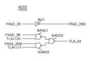
도 2는 도 1의 컬럼 제어부의 실시예에 따른 회로도이다.FIG. 2 is a circuit diagram according to an embodiment of the column controller of FIG. 1.
도 2를 참조하면, 컬럼 제어부(500)는, 페이지 크기 조절신호(PAGE_2K)와, 제1 컬럼 어드레스 비트신호(TLA<11>)와, 제2 컬럼 어드레스 비트신호(TLA<13>)를 논리조합하여 비트 구성 조절신호(TLA_X4)로서 출력하는 로직부(NAND1 ,NAND2 ,NAND3)로 구성된다.Referring to FIG. 2, the
즉, 로직부는 페이지 크기 조절신호(PAGE_2K)와 제2 컬럼 어드레스 비트신호(TLA<13>)를 입력으로 하는 제1 부정 논리곱 수단(NAND1)과, 페이지 크기 조절신호의 반전신호(PAGE_2KB)와 제1 컬럼 어드레스 비트신호(TLA<11>)를 입력으로 하는 제2 부정 논리곱 수단(NAND2)과, 제1 부정 논리곱 수단(NAND1)의 출력신호 및 제2 부정 논리곱 수단(NAND2)의 출력신호를 입력으로 하여 비트 구성 조절신호(TLA_X4)를 출력하는 제3 부정 논리곱 수단(NAND3)으로 구성된다.
That is, the logic unit may include the first negative AND product NAND1 that inputs the page size control signal PAGE_2K and the second column address bit signal TLA <13>, and the inversion signal PAGE_2KB of the page size control signal. The second negative AND unit NAND2 that receives the first column address bit signal TLA <11>, the output signal of the first negative AND unit NAND1, and the second negative AND unit NAND2. And a third negative AND product NAND3 for outputting the bit configuration adjustment signal TLA_X4 as an output signal.
컬럼 제어부(500)는 페이지 크기 조절신호(PAGE_2K)가 로우레벨이면 즉, 1K 페이지 크기의 메모리 셀을 액세스 하도록 지시하면, 제1 컬럼 어드레스 비트신호(TLA<11>)를 비트 구성 조절신호(TLA_X4)로서 출력한다.When the page size control signal PAGE_2K is at a low level, that is, when the
또한, 컬럼 제어부(500)는 페이지 크기 조절신호(PAGE_2K)가 하이레벨이면 즉, 2K 페이지 크기의 메모리 셀을 액세스 하도록 지시하면, 제2 컬럼 어드레스 비트신호(TLA<13>)를 비트 구성 조절신호(TLA_X4)로서 출력한다.
Further, when the page size control signal PAGE_2K is at a high level, that is, when the
컬럼 선택신호 발생부(600)는 컬럼 펄스신호(CASP)에 응답하여 컬럼 어드레스(TLA<2:9>,TLA<11>)를 복수의 컬럼 선택신호(YADD<2:9>,YADD<11>)로서 출력한다. 또한, 컬럼 선택신호 발생부(600)는 비트 구성 조절신호(TLA_X4)를 옵션 컬럼 선택신호(YADD_X4)로서 출력한다. 즉, 컬럼 선택신호 발생부(600)는 컬럼 펄스신호(CASP)가 하이레벨로 펄싱할 때, 복수의 컬럼 선택신호(YADD<2:9>,YADD<11>) 및 옵션 컬럼 선택신호(YADD_X4)를 출력한다. 또한, 컬럼 선택신호 발생부(600)는 뱅크 어드레스(TLBA<0:2>)를 디코딩 하여 복수의 컬럼 뱅크 선택신호(CACTV<0:7>)를 출력한다. 본 실시예에서는 제1 뱅크(BANK0)가 선택된 경우만을 대표적으로 도시하였으므로, 제1 컬럼 뱅크 선택신호(CACTV<0>)가 활성화된다.The column
여기에서 컬럼 선택신호 발생부(600)는, 컬럼 어드레스(TLA<2:9>,TLA<11>,TLA<13>) 중 최상위 컬럼 어드레스 비트신호(TLA<13>)를 제외한 컬럼 어드레스(TLA<2:9>,TLA<11>)를 복수의 컬럼 선택신호(YADD<2:9>,YADD<11>)로서 출력하고, 비트 구성 조절신호(TLA_X4)를 옵션 컬럼 선택신호(YADD_X4)로서 출력한다.
Here, the column
페이지 크기 제어부(400)는, 페이지 크기 조절신호(PAGE_2K)의 제어에 따라, 복수의 로우 선택신호(XADD<0:16>) 중 어느 하나의 로우 선택신호(XADD<16>)에 대응하는 레벨을 갖는 제1 블록 인에이블 신호(UP_EN) 및 제2 블록 인에이블 신호(DN_EN)를 생성하거나, 복수의 컬럼 선택신호(YADD<2:9>,YADD<11>) 중 어느 하나의 컬럼 선택신호(YADD<11>)에 대응하는 레벨을 갖는 제1 블록 인에이블 신호(UP_EN) 및 제2 블록 인에이블 신호(DN_EN)를 생성한다. 여기에서 제1 블록 인에이블 신호(UP_EN)와 제2 블록 인에이블 신호(DN_EN)는 서로 반대의 레벨을 갖는 신호로 정의된다.
The page
참고적으로, 본 실시예에서 복수의 로우 선택신호(XADD<0:16>) 중 어느 하나의 로우 선택신호(XADD<16>)는 로우 어드레스(TLA<0:16>) 중 최상위 로우 어드레스 비트신호(TLA<16>)에 대응하는 신호이다. 또한, 복수의 컬럼 선택신호(YADD<2:9>,YADD<11>) 중 어느 하나의 컬럼 선택신호(YADD<11>)는 컬럼 어드레스(TLA<2:9>,TLA<11>,TLA<13>) 중 최상위 컬럼 어드레스 비트신호(TLA<13>)에 이웃하는 컬럼 어드레스 비트신호(TLA<11>)에 대응하는 신호이다.
For reference, in the present exemplary embodiment, any one of the row select signals XADD <16> of the plurality of row select signals XADD <0:16> is the most significant row address bit among the row addresses TLA <0:16>. This signal corresponds to the signal TLA <16>. In addition, any one of the column selection signals YADD <2: 9> and YADD <11> may include the column addresses TLA <2: 9>, TLA <11>, and TLA. <13>) is a signal corresponding to the column address bit signal TLA <11> adjacent to the most significant column address bit signal TLA <13>.
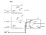
도 3은 도 1의 페이지 크기 제어부의 실시예에 따른 회로도이다.3 is a circuit diagram of an embodiment of the page size controller of FIG. 1.
도 3을 참조하면, 페이지 크기 제어부(400)는 제1 로직부(410)와, 제2 로직부(420)와, 제3 로직부(430)로 구성된다.
Referring to FIG. 3, the page
제1 로직부(410)는 액티브 펄스신호(ACTP)에 응답하여 로우 선택신호(XADD<16>)를 선택적으로 출력한다. 제1 로직부(410)를 좀 더 상세히 살펴보면, 로우 선택신호(XADD<16>)는 제1 트랜스미션 게이트(TG1)에 입력되어 선택적으로 출력되는데, 제1 트랜스미션 게이트(TG1)는, 액티브 펄스신호(ACTP) 및 제1 로우 뱅크 선택신호(RACTV<0>)를 입력받는 제1 논리곱 수단(AND1)의 출력신호의 제어에 따라 온오프(On-Off)된다.The
제2 로직부(420)는 컬럼 펄스신호(CASP)에 응답하여 제1 로직부(410)에서 출력되는 신호(UP_LATCH)를 선택적으로 출력한다. 제2 로직부(420)를 좀 더 상세히 살펴보면, 제1 로직부(410)에서 출력되는 신호(UP_LATCH)는 제2 트랜스미션 게이트(TG2)에 입력되어 선택적으로 출력되는데, 제2 트랜스미션 게이트(TG2)는, 컬럼 펄스신호(CASP) 및 제1 컬럼 뱅크 선택신호(CACTV<0>)를 입력받는 제2 논리곱 수단(AND2)의 출력신호의 제어에 따라 온오프(On-Off)된다.The
제3 로직부(430)는 페이지 크기 조절신호(PAGE_2K)의 제어에 따라, 제2 로직부(420)에서 출력되는 신호 또는 컬럼 선택신호(YADD<11>)를 제1 블록 인에이블 신호(UP_EN) 및 제2 블록 인에이블 신호(DN_EN)로서 선택적으로 출력한다. 여기에서 제1 블록 인에이블 신호(UP_EN) 및 제2 블록 인에이블 신호(DN_EN)는 서로 반대의 레벨을 갖도록 출력한다. 제3 로직부(430)는 페이지 크기 조절신호(PAGE_2K)와, 컬럼 선택신호(YADD<11>)와, 제2 로직부(420)의 출력신호를 복수의 부정 논리곱 수단(NAND1,NAND2,NAND3) 및 복수의 인버터(INV3,INV4)를 이용하여 논리조합한 이후에, 제1 블록 인에이블 신호(UP_EN) 및 제2 블록 인에이블 신호(DN_EN)로서 출력한다.The
즉, 페이지 크기 제어부(400)는 페이지 크기 조절신호(PAGE_2K)가 로우레벨이고, 액티브 동작과 읽기/쓰기 동작시의 뱅크 정보가 같을 때, 즉, 제1 로우 뱅크 선택신호(RACTV<0>) 및 제1 컬럼 뱅크 선택신호(CACTV<0>)가 동일할 때, 로우 선택신호(XADD<16>)를 이용하여 제1 블록 인에이블 신호(UP_EN) 및 제2 블록 인에이블 신호(DN_EN)를 생성한다.That is, the page
또한, 즉, 페이지 크기 제어부(400)는 페이지 크기 조절신호(PAGE_2K)가 하이레벨 일 때, 컬럼 선택신호(YADD<11>)를 이용하여 제1 블록 인에이블 신호(UP_EN) 및 제2 블록 인에이블 신호(DN_EN)를 생성한다.
In other words, when the page size control signal PAGE_2K is at the high level, the page
페이지 크기 제어부(400)는 페이지 크기 조절신호(PAGE_2K)가 제1 레벨이면, 즉 하이레벨이면 2K 페이지 크기의 메모리 셀을 액세스 하도록, 컬럼 선택신호(YADD<11>)에 대응하는 레벨을 갖는 제1 블록 인에이블 신호(UP_EN) 및 제2 블록 인에이블 신호(DN_EN)를 생성한다.If the page size control signal PAGE_2K is at a first level, that is, at a high level, the page
또한, 페이지 크기 제어부(400)는 페이지 크기 조절신호(PAGE_2K)가 제2 레벨이면, 즉 로우레벨이면 1K 페이지 크기의 메모리 셀을 액세스 하도록, 로우 선택신호(XADD<16>)에 대응하는 레벨을 갖는 제1 블록 인에이블 신호(UP_EN) 및 제2 블록 인에이블 신호(DN_EN)를 생성한다.In addition, the page
여기에서 복수의 로우 선택신호(XADD<0:16>) 중 어느 하나의 로우 선택신호(XADD<16>)는 로우 어드레스(TLA<0:16>) 중 최상위 로우 어드레스 비트신호(TLA<16>)에 대응하는 신호이다. 또한, 복수의 컬럼 선택신호(YADD<2:9>,YADD<11>) 중 어느 하나의 컬럼 선택신호(YADD<11>)는 컬럼 어드레스(TLA<2:9>,TLA<11>,TLA<13>) 중 최상위 컬럼 어드레스 비트신호(TLA<13>)에 이웃하는 컬럼 어드레스 비트신호(TLA<11>)에 대응하는 신호로 정의된다.
The row select signal XADD <16> of any of the plurality of row select signals XADD <0:16> is the most significant row address bit signal TLA <16> among the row addresses TLA <0:16>. Is a signal corresponding to In addition, any one of the column selection signals YADD <2: 9> and YADD <11> may include the column addresses TLA <2: 9>, TLA <11>, and TLA. <13>) is defined as a signal corresponding to the column address bit signal TLA <11> adjacent to the highest column address bit signal TLA <13>.
메모리 블록(700)은 메모리 셀 어레이(미도시됨)로 구성되며 복수의 뱅크로 구분되나, 본 실시예에서는 하나의 뱅크(BANK0)에 포함된 제1 페이지 블록(710) 및 제2 페이지 블록(720)만을 대표적으로 도시하였다. 참고적으로, 1K 페이지 크기는 하나의 로우 선택신호에 의해서 선택되는 복수의 메모리 셀(미도시됨)의 개수를 의미한다. 따라서 제1 페이지 블록(710)이 로우 선택신호에 의해서 선택되면 1K 개의 메모리 셀들(미도시됨)이 제어된다. 또한, 제2 페이지 블록(720)이 로우 선택신호에 의해서 선택되면 1K 개의 메모리 셀들(미도시됨)이 제어된다.
The
제1 페이지 블록(710)은, 제1 블록 인에이블 신호(UP_EN)에 응답하여 복수의 로우 선택신호(XADD<0:15>)에 의해 선택된 복수의 제1 메모리 셀(미도시됨)을 활성화 시키고, 선택된 복수의 제1 메모리 셀 중 복수의 컬럼 선택신호(YADD<2:9>,YADD<11>) 및 옵션 컬럼 선택신호(YADD_X4)에 의해 선택된 메모리 셀의 데이터 액세스를 활성화 시킨다.The
제2 페이지 블록(720)은, 제2 블록 인에이블 신호(DN_EN)에 응답하여 복수의 로우 선택신호(XADD<0:15>)에 의해 선택된 복수의 제2 메모리 셀(미도시됨)을 활성화 시키고, 선택된 복수의 2 메모리 셀 중 복수의 컬럼 선택신호(YADD<2:9>,YADD<11>) 및 옵션 컬럼 선택신호(YADD_X4)에 의해 선택된 메모리 셀의 데이터 액세스를 활성화 시킨다.
The
즉, 페이지 크기 조절신호(PAGE_2K)가 로우레벨이 되면, 로우 선택신호(XADD<16>)에 의해서 제1 블록 인에이블 신호(UP_EN) 및 제2 블록 인에이블 신호(DN_EN)의 신호 레벨이 결정되므로, 1K 페이지의 메모리 셀에 대한 데이터를 액세스 할 수 있다. 이때, 비트 구성(Bit Organization)이 X4일 경우, 옵션 컬럼 선택신호(YADD_X4)가 컬럼 선택신호(YADD<11>)에 대응되는 레벨을 가지므로 옵션 컬럼 선택신호(YADD_X4)를 통해서 컬럼 액세스를 제어한다.That is, when the page size control signal PAGE_2K is at the low level, the signal levels of the first block enable signal UP_EN and the second block enable signal DN_EN are determined by the row select signal XADD <16>. Thus, data for memory cells of 1K pages can be accessed. At this time, when the bit organization is X4, the column access control is performed through the option column selection signal YADD_X4 since the option column selection signal YADD_X4 has a level corresponding to the column selection signal YADD <11>. do.
또한, 페이지 크기 조절신호(PAGE_2K)가 하이레벨이 되면, 컬럼 선택신호(YADD<11>)에 의해서 제1 블록 인에이블 신호(UP_EN) 및 제2 블록 인에이블 신호(DN_EN)의 신호 레벨이 결정되므로, 2K 페이지의 메모리 셀에 대한 데이터를 액세스 할 수 있다. 이때, 비트 구성(Bit Organization)이 X4일 경우, 옵션 컬럼 선택신호(YADD_X4)가 컬럼 선택신호(YADD<13>)에 대응되는 레벨을 가지므로 옵션 컬럼 선택신호(YADD_X4)를 통해서 컬럼 액세스를 제어한다.
In addition, when the page size control signal PAGE_2K is at the high level, the signal levels of the first block enable signal UP_EN and the second block enable signal DN_EN are determined by the column select signal YADD <11>. Thus, data for memory cells of 2K pages can be accessed. At this time, when the bit organization is X4, since the option column selection signal YADD_X4 has a level corresponding to the column selection signal YADD <13>, the column access is controlled through the option column selection signal YADD_X4. do.
결과적으로 본 실시예에 따른 반도체 메모리 장치는 페이지 크기를 자유롭게 변환 할 수 있으며, 비트 구성(Bit Organization)에 따라 데이터 액세스를 조절할 수 있다.
As a result, the semiconductor memory device according to the present embodiment can freely convert the page size and control the data access according to the bit organization.
COL_ADDR<0:9,11>ROW_ADDR <0:15>
COL_ADDR <0: 9,11>
COL_ADDR<0:9>ROW_ADDR <0:15>
COL_ADDR <0: 9>
COL_ADDR<0:9,11>ROW_ADDR <0:16>
COL_ADDR <0: 9,11>
COL_ADDR<0:9>ROW_ADDR <0:16>
COL_ADDR <0: 9>
COL_ADDR<0:9,11,13>ROW_ADDR <0:15>
COL_ADDR <0: 9,11,13>
COL_ADDR<0:9,11>ROW_ADDR <0:15>
COL_ADDR <0: 9,11>
표 1은 본 발명의 일 실시예에 따른 반도체 메모리 장치의 비트 구성(Bit Organization) 및 페이지 크기 변경시에 할당되는 로우 및 컬럼 어드레스의 비트 수를 나타낸 표이다.Table 1 is a table showing the bit structure of the semiconductor memory device and the number of bits of the row and column addresses allocated when changing the page size according to an embodiment of the present invention.
참고적으로, 로우 어드레스 및 컬럼 어드레스는 각각의 커맨드와 함께, 어드레스 멀티플렉싱 방식을 통해서 순차적으로 입력된다. 따라서 표 1에서는 내부에 래치된 로우 어드레스를 "ROW_ADDR" 이라고 표시하고, 내부에 래치된 컬럼 어드레스를 "COL_ADDR" 이라고 표시하기로 한다.For reference, the row address and the column address are sequentially input through the address multiplexing method together with the respective commands. Therefore, in Table 1, the row address latched inside is denoted as "ROW_ADDR", and the column address latched inside is denoted as "COL_ADDR".
표 1을 참조하면, 반도체 메모리 장치의 저장용량이 증가할 때, 추가적인 로우 어드레스 및 컬럼 어드레스를 할당하여, 페이지 크기를 가변할 수 있으며, 비트 구성(Bit Organization)의 변경에도 대응할 수 있다.
Referring to Table 1, when the storage capacity of the semiconductor memory device increases, an additional row address and a column address may be allocated to change the page size, and may correspond to a change in the bit organization.
본 발명의 실시예에서는 한정된 크기의 페이지를 조절하는 예시를 기술하였으나, 실시예에 따라 다양한 크기의 페이지를 조절할 수 있으며, 추가적인 로우 어드레스 비트신호 및 추가적인 컬럼 어드레스 비트신호를 할당하여 비트 구성(Bit Organization)에 따른 페이지 크기를 조절할 수도 있을 것이다.In an embodiment of the present invention, an example of adjusting a page of a limited size is described, but a page of various sizes may be adjusted according to an embodiment, and a bit structure may be allocated by assigning an additional row address bit signal and an additional column address bit signal. You can also adjust the page size.
이와 같이, 본 발명이 속하는 기술분야의 당업자는 본 발명이 그 기술적 사상이나 필수적 특징을 변경하지 않고서 다른 구체적인 형태로 실시될 수 있다는 것을 이해할 수 있을 것이다. 그러므로 이상에서 기술한 실시예들은 모든 면에서 예시적인 것이며 한정적인 것이 아닌 것으로서 이해해야만 한다. 본 발명의 범위는 상기 상세한 설명보다는 후술하는 특허청구범위에 의하여 나타내어지며, 특허청구범위의 의미 및 범위 그리고 그 등가개념으로부터 도출되는 모든 변경 또는 변형된 형태가 본 발명의 범위에 포함되는 것으로 해석되어야 한다.
Thus, those skilled in the art will appreciate that the present invention may be embodied in other specific forms without departing from the spirit or essential characteristics thereof. It is therefore to be understood that the embodiments described above are to be considered in all respects only as illustrative and not restrictive. The scope of the present invention is defined by the appended claims rather than the detailed description and all changes or modifications derived from the meaning and scope of the claims and their equivalents are to be construed as being included within the scope of the present invention do.
100 : 신호 입력부
410 : 제1 로직부
420 : 제2 로직부
413 : 제3 로직부100: signal input unit
410: the first logic unit
420: second logic unit
413: third logic part
Claims (28)
Translated fromKorean페이지 크기 조절신호의 제어에 따라, 컬럼 어드레스 중 제1 컬럼 어드레스 비트신호 또는 제2 컬럼 어드레스 비트신호를 비트 구성 조절신호로서 선택적으로 할당하여 출력하는 컬럼 제어부;
컬럼 펄스신호에 응답하여 상기 컬럼 어드레스를 복수의 컬럼 선택신호로서 출력하고, 상기 비트 구성 조절신호를 옵션 컬럼 선택신호로서 출력하는 컬럼 선택신호 발생부;
상기 페이지 크기 조절신호의 제어에 따라, 상기 복수의 로우 선택신호 중 어느 하나의 로우 선택신호에 대응하는 레벨을 갖는 제1 및 제2 블록 인에이블 신호를 생성하거나, 상기 복수의 컬럼 선택신호 중 어느 하나의 컬럼 선택신호에 대응하는 레벨을 갖는 상기 제1 및 제2 블록 인에이블 신호를 생성하는 페이지 크기 제어부;
상기 제1 블록 인에이블 신호에 응답하여 상기 복수의 로우 선택신호에 의해 선택된 복수의 제1 메모리 셀을 활성화 시키고, 선택된 상기 복수의 제1 메모리 셀 중 상기 복수의 컬럼 선택신호 및 상기 옵션 컬럼 선택신호에 의해 선택된 메모리 셀의 데이터 액세스를 활성화 시키는 제1 페이지 블록; 및
상기 제2 블록 인에이블 신호에 응답하여 상기 복수의 로우 선택신호에 의해 선택된 복수의 제2 메모리 셀을 활성화 시키고, 선택된 상기 복수의 2 메모리 셀 중 상기 복수의 컬럼 선택신호 및 상기 옵션 컬럼 선택신호에 의해 선택된 메모리 셀의 데이터 액세스를 활성화 시키는 제2 페이지 블록;
을 포함하는 반도체 메모리 장치.
A row select signal generator for outputting a row address as a plurality of row select signals in response to an active pulse signal;
A column controller for selectively allocating a first column address bit signal or a second column address bit signal among the column addresses as a bit configuration control signal according to the control of the page size adjustment signal;
A column select signal generator for outputting the column address as a plurality of column select signals in response to a column pulse signal, and outputting the bit configuration adjustment signal as an optional column select signal;
According to the control of the page size control signal, the first and second block enable signals having a level corresponding to any one of the plurality of row selection signals are generated or one of the plurality of column selection signals is generated. A page size controller configured to generate the first and second block enable signals having a level corresponding to one column selection signal;
Activating a plurality of first memory cells selected by the plurality of row selection signals in response to the first block enable signal, wherein the plurality of column selection signals and the option column selection signals of the plurality of selected first memory cells are activated; A first page block for activating data access of the memory cell selected by; And
Activate a plurality of second memory cells selected by the plurality of row select signals in response to the second block enable signal, and apply the plurality of column select signals and the option column select signals of the selected plurality of two memory cells; A second page block for activating data access of the selected memory cell;
Semiconductor memory device comprising a.
상기 복수의 로우 선택신호 중 어느 하나의 로우 선택신호는 상기 로우 어드레스 중 최상위 로우 어드레스 비트신호에 대응하는 로우 선택신호인 것을 특징으로 하는 반도체 메모리 장치.
The method of claim 1,
And one row select signal of the plurality of row select signals is a row select signal corresponding to a most significant row address bit signal of the row addresses.
상기 복수의 컬럼 선택신호 중 어느 하나의 컬럼 선택신호는 상기 컬럼 어드레스 중 최상위 컬럼 어드레스 비트신호에 이웃하는 컬럼 어드레스 비트신호에 대응하는 컬럼 선택신호인 것을 특징으로 하는 반도체 메모리 장치.
The method of claim 1,
And any one column selection signal of the plurality of column selection signals is a column selection signal corresponding to a column address bit signal neighboring the most significant column address bit signal of the column addresses.
상기 컬럼 선택신호 발생부는,
상기 컬럼 어드레스 중 최상위 컬럼 어드레스 비트신호를 제외한 컬럼 어드레스를 상기 복수의 컬럼 선택신호로서 출력하고, 상기 비트 구성 조절신호를 상기 옵션 컬럼 선택신호로서 출력하는 것을 특징으로 하는 반도체 메모리 장치.
The method of claim 1,
The column select signal generator,
And a column address excluding the most significant column address bit signal among the column addresses as the plurality of column selection signals, and outputting the bit configuration adjustment signal as the option column selection signal.
상기 페이지 크기 제어부는,
상기 페이지 크기 조절신호가 제1 레벨이면, 상기 복수의 컬럼 선택신호 중 어느 하나의 컬럼 선택신호에 대응하는 레벨을 갖는 상기 제1 및 제2 블록 인에이블 신호를 생성하며, 상기 제1 및 제2 블록 인에이블 신호는 서로 반대 레벨을 갖는 것을 특징으로 하는 반도체 메모리 장치.
The method of claim 1,
The page size control unit,
If the page size control signal is a first level, the first and second block enable signals having a level corresponding to any one of the plurality of column selection signals are generated, and the first and second blocks are enabled. The block enable signal has a level opposite to each other.
상기 페이지 크기 제어부는,
상기 페이지 크기 조절신호가 제2 레벨이면, 상기 복수의 로우 선택신호 중 어느 하나의 로우 선택신호에 대응하는 레벨을 갖는 상기 제1 및 제2 블록 인에이블 신호를 생성하며, 상기 제1 및 제2 블록 인에이블 신호는 서로 반대 레벨을 갖는 것을 특징으로 하는 반도체 메모리 장치.
The method of claim 5,
The page size control unit,
If the page size control signal is the second level, the first and second block enable signals having a level corresponding to any one of the plurality of row selection signals are generated, and the first and second blocks are generated. The block enable signal has a level opposite to each other.
상기 복수의 로우 선택신호 중 어느 하나의 로우 선택신호는 상기 로우 어드레스 중 최상위 로우 어드레스 비트신호에 대응하는 로우 선택신호이며, 상기 복수의 컬럼 선택신호 중 어느 하나의 컬럼 선택신호는 상기 컬럼 어드레스 중 최상위 컬럼 어드레스 비트신호에 이웃하는 컬럼 어드레스 비트신호에 대응하는 컬럼 선택신호인 것을 특징으로 하는 반도체 메모리 장치.
The method of claim 6,
One of the row select signals of the plurality of row select signals is a row select signal corresponding to the highest row address bit signal among the row addresses, and one of the column select signals of the plurality of column select signals is the highest among the column addresses. And a column select signal corresponding to a column address bit signal adjacent to the column address bit signal.
상기 페이지 크기 제어부는,
상기 액티브 펄스신호에 응답하여 어느 하나의 상기 로우 선택신호를 선택적으로 출력하는 제1 로직부;
상기 컬럼 펄스신호에 응답하여 상기 제1 로직부에서 출력되는 신호를 선택적으로 출력하는 제2 로직부; 및
상기 페이지 크기 조절신호의 제어에 따라, 상기 제2 로직부에서 출력되는 신호 또는 어느 하나의 상기 컬럼 선택신호를 상기 제1 및 제2 블록 인에이블 신호로서 선택적으로 출력함에 있어서, 상기 제1 및 제2 블록 인에이블 신호가 서로 반대의 레벨을 갖도록 출력하는 제3 로직부;를 포함하는 반도체 메모리 장치.
The method of claim 1,
The page size control unit,
A first logic unit selectively outputting any one of the row selection signals in response to the active pulse signal;
A second logic unit selectively outputting a signal output from the first logic unit in response to the column pulse signal; And
In response to the control of the page size control signal, selectively outputting the signal output from the second logic unit or any one of the column selection signals as the first and second block enable signals. And a third logic unit configured to output the two block enable signals to have opposite levels from each other.
상기 컬럼 제어부는,
상기 페이지 크기 조절신호와, 상기 제1 컬럼 어드레스 비트신호와, 제2 컬럼 어드레스 비트신호를 논리조합하여 상기 비트 구성 조절신호로서 출력하는 로직부;를 포함하는 반도체 메모리 장치.
The method of claim 1,
The column control unit,
And a logic unit for logically combining the page size control signal, the first column address bit signal, and the second column address bit signal as the bit configuration control signal.
클럭신호의 제어에 따라 외부 로우 어드레스 및 외부 컬럼 어드레스를 버퍼링하여 저장하며, 저장된 신호를 상기 로우 어드레스 및 상기 컬럼 어드레스로서 출력하는 로우/컬럼 어드레스 입력부;
상기 클럭신호의 제어에 따라 외부 뱅크 어드레스를 버퍼링하여 저장하며, 저장된 신호를 뱅크 어드레스로서 출력하는 뱅크 어드레스 입력부;
상기 클럭신호의 제어에 따라 복수의 외부 커맨드 신호를 버퍼링하여 저장하며, 저장된 신호를 복수의 커맨드 신호로서 출력하는 커맨드 입력부; 및
상기 복수의 커맨드 신호를 디코딩 하여 내부 커맨드로서 출력하는 내부 커맨드 생성부;를 더 포함하는 반도체 메모리 장치.
The method of claim 1,
A row / column address input unit for buffering and storing an external row address and an external column address according to a control of a clock signal, and outputting the stored signals as the row address and the column address;
A bank address input unit for buffering and storing an external bank address according to the control of the clock signal, and outputting the stored signal as a bank address;
A command input unit for buffering and storing a plurality of external command signals according to the control of the clock signal, and outputting the stored signals as a plurality of command signals; And
And an internal command generator to decode the plurality of command signals and output the decoded commands as internal commands.
상기 내부 커맨드는 상기 액티브 펄스신호 및 상기 컬럼 펄스신호를 포함하는 것을 특징으로 하는 반도체 메모리 장치.
The method of claim 10,
And the internal command includes the active pulse signal and the column pulse signal.
상기 복수의 외부 커맨드 신호는 /RAS, /CAS, /WE 및 /CS<0:2>를 포함하는 것을 특징으로 하는 반도체 메모리 장치.
The method of claim 10,
And the plurality of external command signals include / RAS, / CAS, / WE, and / CS <0: 2>.
상기 /CS<2> 신호는 칩 선택신호 또는 외부 로우 어드레스 비트신호로서 사용되는 되는 것을 특징으로 하는 반도체 메모리 장치.
The method of claim 12,
And the / CS <2> signal is used as a chip select signal or an external row address bit signal.
상기 페이지 크기 조절신호는 퓨즈부에서 출력되는 신호인 것을 특징으로 하는 반도체 메모리 장치.
The method of claim 1,
And the page size control signal is a signal output from a fuse unit.
상기 페이지 크기 조절신호는 모드 레지스터 셋(Mode Register Set, MRS)에 설정된 신호를 이용하여 생성되는 것을 특징으로 하는 반도체 메모리 장치.
The method of claim 1,
And the page size control signal is generated using a signal set in a mode register set (MRS).
상기 외부 로우 어드레스 및 상기 외부 컬럼 어드레스는 어드레스 멀티플렉싱 방식을 통해서 순차적으로 입력되는 것을 특징으로 하는 반도체 메모리 장치.
The method of claim 10,
And the external row address and the external column address are sequentially input through an address multiplexing method.
상기 제1 블록 인에이블 신호에 응답하여 상기 복수의 로우 선택신호에 의해 선택된 복수의 제1 메모리 셀을 활성화 시키고, 선택된 상기 복수의 제1 메모리 셀 중 상기 복수의 컬럼 선택신호 및 옵션 컬럼 선택신호에 의해 선택된 메모리 셀의 데이터 액세스를 활성화 시키는 제1 페이지 블록; 및
상기 제2 블록 인에이블 신호에 응답하여 상기 복수의 로우 선택신호에 의해 선택된 복수의 제2 메모리 셀을 활성화 시키고, 선택된 상기 복수의 2 메모리 셀 중 상기 복수의 컬럼 선택신호 및 상기 옵션 컬럼 선택신호에 의해 선택된 메모리 셀의 데이터 액세스를 활성화 시키는 제2 페이지 블록;
을 포함하는 반도체 메모리 장치.
According to the control of the page size control signal, the first and second block enable signals having a level corresponding to any one of the plurality of row selection signals are generated, or one of the plurality of column selection signals is generated. A page size controller configured to generate the first and second block enable signals having a level corresponding to a selection signal;
Activating a plurality of first memory cells selected by the plurality of row selection signals in response to the first block enable signal, and applying the plurality of column selection signals and option column selection signals of the plurality of selected first memory cells; A first page block for activating data access of the selected memory cell; And
Activate a plurality of second memory cells selected by the plurality of row select signals in response to the second block enable signal, and apply the plurality of column select signals and the option column select signals of the selected plurality of two memory cells; A second page block for activating data access of the selected memory cell;
Semiconductor memory device comprising a.
상기 복수의 로우 선택신호 중 어느 하나의 로우 선택신호는 로우 어드레스 중 최상위 로우 어드레스 비트신호에 대응하는 로우 선택신호인 것을 특징으로 하는 반도체 메모리 장치.
18. The method of claim 17,
And a row select signal of the plurality of row select signals is a row select signal corresponding to the most significant row address bit signal among the row addresses.
상기 복수의 컬럼 선택신호 중 어느 하나의 컬럼 선택신호는 컬럼 어드레스 중 최상위 컬럼 어드레스 비트신호에 이웃하는 컬럼 어드레스 비트신호에 대응하는 컬럼 선택신호인 것을 특징으로 하는 반도체 메모리 장치.
19. The method of claim 18,
And a column select signal of the plurality of column select signals is a column select signal corresponding to a column address bit signal adjacent to the highest column address bit signal among the column addresses.
상기 로우 어드레스 및 상기 컬럼 어드레스는 어드레스 멀티플렉싱 방식을 통해서 순차적으로 입력되는 것을 특징으로 하는 반도체 메모리 장치.
20. The method of claim 19,
And the row address and the column address are sequentially input through an address multiplexing method.
상기 페이지 크기 제어부는,
상기 페이지 크기 조절신호가 제1 레벨이면, 상기 복수의 컬럼 선택신호 중 어느 하나의 컬럼 선택신호에 대응하는 레벨을 갖는 상기 제1 및 제2 블록 인에이블 신호를 생성하며, 상기 제1 및 제2 블록 인에이블 신호는 서로 반대 레벨을 갖는 것을 특징으로 하는 반도체 메모리 장치.
18. The method of claim 17,
The page size control unit,
If the page size control signal is a first level, the first and second block enable signals having a level corresponding to any one of the plurality of column selection signals are generated, and the first and second blocks are enabled. The block enable signal has a level opposite to each other.
상기 페이지 크기 제어부는,
상기 페이지 크기 조절신호가 제2 레벨이면, 상기 복수의 로우 선택신호 중 어느 하나의 로우 선택신호에 대응하는 레벨을 갖는 상기 제1 및 제2 블록 인에이블 신호를 생성하며, 상기 제1 및 제2 블록 인에이블 신호는 서로 반대 레벨을 갖는 것을 특징으로 하는 반도체 메모리 장치.
The method of claim 21,
The page size control unit,
If the page size control signal is the second level, the first and second block enable signals having a level corresponding to any one of the plurality of row selection signals are generated, and the first and second blocks are generated. The block enable signal has a level opposite to each other.
상기 복수의 로우 선택신호 중 어느 하나의 로우 선택신호는 로우 어드레스 중 최상위 로우 어드레스 비트신호에 대응하는 로우 선택신호이며, 상기 복수의 컬럼 선택신호 중 어느 하나의 컬럼 선택신호는 컬럼 어드레스 중 최상위 컬럼 어드레스 비트신호에 이웃하는 컬럼 어드레스 비트신호에 대응하는 컬럼 선택신호인 것을 특징으로 하는 반도체 메모리 장치.
The method of claim 22,
One of the row selection signals of the plurality of row selection signals is a row selection signal corresponding to the most significant row address bit signal of the row addresses, and one of the column selection signals of the plurality of column selection signals is the most significant column address of the column addresses. And a column select signal corresponding to a column address bit signal adjacent to the bit signal.
상기 페이지 크기 제어부는,
액티브 펄스신호에 응답하여 어느 하나의 상기 로우 선택신호를 선택적으로 출력하는 제1 로직부;
컬럼 펄스신호에 응답하여 상기 제1 로직부에서 출력되는 신호를 선택적으로 출력하는 제2 로직부; 및
상기 페이지 크기 조절신호의 제어에 따라 상기 제2 로직부에서 출력되는 신호 또는 어느 하나의 상기 컬럼 선택신호를 상기 제1 및 제2 블록 인에이블 신호로서 선택적으로 출력함에 있어서, 상기 제1 및 제2 블록 인에이블 신호가 서로 반대의 레벨을 갖도록 출력하는 제3 로직부;를 포함하는 반도체 메모리 장치.
18. The method of claim 17,
The page size control unit,
A first logic unit selectively outputting any one of the row selection signals in response to an active pulse signal;
A second logic unit selectively outputting a signal output from the first logic unit in response to a column pulse signal; And
Selectively outputting the signal selected from the second logic unit or any one of the column selection signals as the first and second block enable signals according to the control of the page size adjustment signal, wherein the first and second And a third logic unit configured to output the block enable signals to have opposite levels from each other.
상기 페이지 크기 조절신호는 퓨즈부에서 출력되는 신호인 것을 특징으로 하는 반도체 메모리 장치.
18. The method of claim 17,
And the page size control signal is a signal output from a fuse unit.
상기 페이지 크기 조절신호는 모드 레지스터 셋(Mode Register Set, MRS)에 설정된 신호를 이용하여 생성되는 것을 특징으로 하는 반도체 메모리 장치.
18. The method of claim 17,
And the page size control signal is generated using a signal set in a mode register set (MRS).
상기 옵션 컬럼 선택신호는 비트 구성 조절신호를 이용하여 생성된 신호인 것을 특징으로 하는 반도체 메모리 장치.
18. The method of claim 17,
And the option column selection signal is a signal generated using a bit configuration control signal.
상기 비트 구성 조절신호는,
상기 페이지 크기 조절신호의 제어에 따라, 컬럼 어드레스 중 어느 하나의 컬럼 어드레스 비트신호를 이용하여 생성된 신호인 것을 특징으로 하는 반도체 메모리 장치.28. The method of claim 27,
The bit configuration control signal,
And a signal generated by using any one of the column address bit signals among the column addresses according to the control of the page size control signal.
Priority Applications (4)
| Application Number | Priority Date | Filing Date | Title |
|---|---|---|---|
| KR1020110019324AKR101190694B1 (en) | 2011-03-04 | 2011-03-04 | Semiconductor memory apparatus |
| US13/171,885US20120224441A1 (en) | 2011-03-04 | 2011-06-29 | Semiconductor memory apparatus |
| TW100129794ATW201237621A (en) | 2011-03-04 | 2011-08-19 | Semiconductor memory apparatus |
| CN2011103018751ACN102655020A (en) | 2011-03-04 | 2011-10-09 | Semiconductor memory apparatus |
Applications Claiming Priority (1)
| Application Number | Priority Date | Filing Date | Title |
|---|---|---|---|
| KR1020110019324AKR101190694B1 (en) | 2011-03-04 | 2011-03-04 | Semiconductor memory apparatus |
Publications (2)
| Publication Number | Publication Date |
|---|---|
| KR20120100435A KR20120100435A (en) | 2012-09-12 |
| KR101190694B1true KR101190694B1 (en) | 2012-10-12 |
Family
ID=46730637
Family Applications (1)
| Application Number | Title | Priority Date | Filing Date |
|---|---|---|---|
| KR1020110019324AExpired - Fee RelatedKR101190694B1 (en) | 2011-03-04 | 2011-03-04 | Semiconductor memory apparatus |
Country Status (4)
| Country | Link |
|---|---|
| US (1) | US20120224441A1 (en) |
| KR (1) | KR101190694B1 (en) |
| CN (1) | CN102655020A (en) |
| TW (1) | TW201237621A (en) |
Families Citing this family (5)
| Publication number | Priority date | Publication date | Assignee | Title |
|---|---|---|---|---|
| KR20150119540A (en)* | 2014-04-15 | 2015-10-26 | 에스케이하이닉스 주식회사 | Semiconductor device |
| US11210019B2 (en) | 2017-08-23 | 2021-12-28 | Micron Technology, Inc. | Memory with virtual page size |
| US10394456B2 (en)* | 2017-08-23 | 2019-08-27 | Micron Technology, Inc. | On demand memory page size |
| CN107885669B (en)* | 2017-11-09 | 2021-06-04 | 上海华力微电子有限公司 | Distributed storage block access circuit |
| KR102844113B1 (en) | 2020-01-13 | 2025-08-11 | 삼성전자주식회사 | Memory device and operating method of memory device |
Citations (2)
| Publication number | Priority date | Publication date | Assignee | Title |
|---|---|---|---|---|
| KR100381957B1 (en) | 2001-01-04 | 2003-04-26 | 삼성전자주식회사 | Nonvolatile semiconductor memory device and data input/output control method thereof |
| KR100546136B1 (en) | 2003-12-04 | 2006-01-24 | 주식회사 하이닉스반도체 | Nonvolatile Ferroelectric Memory Devices with Wide Page Buffers |
Family Cites Families (6)
| Publication number | Priority date | Publication date | Assignee | Title |
|---|---|---|---|---|
| JP4203384B2 (en)* | 2003-09-11 | 2008-12-24 | パナソニック株式会社 | Semiconductor device |
| JP4808070B2 (en)* | 2006-05-18 | 2011-11-02 | 富士通セミコンダクター株式会社 | Semiconductor memory and operation method of semiconductor memory |
| JP2008108417A (en)* | 2006-10-23 | 2008-05-08 | Hynix Semiconductor Inc | Low power dram and its driving method |
| US7817470B2 (en)* | 2006-11-27 | 2010-10-19 | Mosaid Technologies Incorporated | Non-volatile memory serial core architecture |
| WO2009097681A1 (en)* | 2008-02-04 | 2009-08-13 | Mosaid Technologies Incorporated | Flexible memory operations in nand flash devices |
| KR101599795B1 (en)* | 2009-01-13 | 2016-03-22 | 삼성전자주식회사 | Semiconductor device for adjusting page size |
- 2011
- 2011-03-04KRKR1020110019324Apatent/KR101190694B1/ennot_activeExpired - Fee Related
- 2011-06-29USUS13/171,885patent/US20120224441A1/ennot_activeAbandoned
- 2011-08-19TWTW100129794Apatent/TW201237621A/enunknown
- 2011-10-09CNCN2011103018751Apatent/CN102655020A/enactivePending
Patent Citations (2)
| Publication number | Priority date | Publication date | Assignee | Title |
|---|---|---|---|---|
| KR100381957B1 (en) | 2001-01-04 | 2003-04-26 | 삼성전자주식회사 | Nonvolatile semiconductor memory device and data input/output control method thereof |
| KR100546136B1 (en) | 2003-12-04 | 2006-01-24 | 주식회사 하이닉스반도체 | Nonvolatile Ferroelectric Memory Devices with Wide Page Buffers |
Also Published As
| Publication number | Publication date |
|---|---|
| CN102655020A (en) | 2012-09-05 |
| TW201237621A (en) | 2012-09-16 |
| KR20120100435A (en) | 2012-09-12 |
| US20120224441A1 (en) | 2012-09-06 |
Similar Documents
| Publication | Publication Date | Title |
|---|---|---|
| JP5160770B2 (en) | Latency control circuit and method thereof, and automatic precharge control circuit and method thereof | |
| KR101599795B1 (en) | Semiconductor device for adjusting page size | |
| US7441156B2 (en) | Semiconductor memory device having advanced test mode | |
| US8125847B2 (en) | Semiconductor memory device and access method thereof | |
| US11355180B2 (en) | Semiconductor devices and semiconductor systems including the same | |
| KR101190694B1 (en) | Semiconductor memory apparatus | |
| US8437209B2 (en) | Integrated circuit | |
| US9842641B2 (en) | Semiconductor device and operating method thereof | |
| US8514650B2 (en) | Semiconductor memory device | |
| KR100735024B1 (en) | Address Translator and Semiconductor Memory Device of Semiconductor Device | |
| KR20110031522A (en) | Memory device, memory system having same and control method thereof | |
| US11495286B2 (en) | Semiconductor devices | |
| JP2012113819A (en) | Automatic precharge control circuit, semiconductor memory device and precharging operation control method | |
| KR100753099B1 (en) | Semiconductor memory device | |
| US7434018B2 (en) | Memory system | |
| KR101040244B1 (en) | Main decoding circuit and semiconductor memory device including same | |
| US8976617B2 (en) | Semiconductor device having plural selection lines selected based on address signal | |
| JP2008084516A (en) | Semiconductor memory device | |
| KR102468283B1 (en) | Control circuit and memory device including the control circuit | |
| KR100640786B1 (en) | Word Line Enable Circuit and Method of Semiconductor Memory Device | |
| JP2007200359A (en) | Storage device, address control method and system | |
| KR20100030869A (en) | Semiconductor memory device and operation method thereof | |
| WO2014132865A1 (en) | Semiconductor device | |
| US20080080294A1 (en) | Semiconductor memory device | |
| KR20110077888A (en) | Bank precharge control circuit of semiconductor device |
Legal Events
| Date | Code | Title | Description |
|---|---|---|---|
| A201 | Request for examination | ||
| PA0109 | Patent application | St.27 status event code:A-0-1-A10-A12-nap-PA0109 | |
| PA0201 | Request for examination | St.27 status event code:A-1-2-D10-D11-exm-PA0201 | |
| D13-X000 | Search requested | St.27 status event code:A-1-2-D10-D13-srh-X000 | |
| D14-X000 | Search report completed | St.27 status event code:A-1-2-D10-D14-srh-X000 | |
| PN2301 | Change of applicant | St.27 status event code:A-3-3-R10-R13-asn-PN2301 St.27 status event code:A-3-3-R10-R11-asn-PN2301 | |
| E701 | Decision to grant or registration of patent right | ||
| PE0701 | Decision of registration | St.27 status event code:A-1-2-D10-D22-exm-PE0701 | |
| PG1501 | Laying open of application | St.27 status event code:A-1-1-Q10-Q12-nap-PG1501 | |
| GRNT | Written decision to grant | ||
| PR0701 | Registration of establishment | St.27 status event code:A-2-4-F10-F11-exm-PR0701 | |
| PR1002 | Payment of registration fee | St.27 status event code:A-2-2-U10-U11-oth-PR1002 Fee payment year number:1 | |
| PG1601 | Publication of registration | St.27 status event code:A-4-4-Q10-Q13-nap-PG1601 | |
| PN2301 | Change of applicant | St.27 status event code:A-5-5-R10-R13-asn-PN2301 St.27 status event code:A-5-5-R10-R11-asn-PN2301 | |
| PN2301 | Change of applicant | St.27 status event code:A-5-5-R10-R13-asn-PN2301 St.27 status event code:A-5-5-R10-R11-asn-PN2301 | |
| FPAY | Annual fee payment | Payment date:20150921 Year of fee payment:4 | |
| PR1001 | Payment of annual fee | St.27 status event code:A-4-4-U10-U11-oth-PR1001 Fee payment year number:4 | |
| FPAY | Annual fee payment | Payment date:20160923 Year of fee payment:5 | |
| PR1001 | Payment of annual fee | St.27 status event code:A-4-4-U10-U11-oth-PR1001 Fee payment year number:5 | |
| FPAY | Annual fee payment | Payment date:20170925 Year of fee payment:6 | |
| PR1001 | Payment of annual fee | St.27 status event code:A-4-4-U10-U11-oth-PR1001 Fee payment year number:6 | |
| LAPS | Lapse due to unpaid annual fee | ||
| PC1903 | Unpaid annual fee | St.27 status event code:A-4-4-U10-U13-oth-PC1903 Not in force date:20181009 Payment event data comment text:Termination Category : DEFAULT_OF_REGISTRATION_FEE | |
| PC1903 | Unpaid annual fee | St.27 status event code:N-4-6-H10-H13-oth-PC1903 Ip right cessation event data comment text:Termination Category : DEFAULT_OF_REGISTRATION_FEE Not in force date:20181009 |