KR101185583B1 - A suture which need not be knotted and a kit comprising the suture - Google Patents
A suture which need not be knotted and a kit comprising the sutureDownload PDFInfo
- Publication number
- KR101185583B1 KR101185583B1KR1020110143929AKR20110143929AKR101185583B1KR 101185583 B1KR101185583 B1KR 101185583B1KR 1020110143929 AKR1020110143929 AKR 1020110143929AKR 20110143929 AKR20110143929 AKR 20110143929AKR 101185583 B1KR101185583 B1KR 101185583B1
- Authority
- KR
- South Korea
- Prior art keywords
- suture
- support
- kit
- communication hole
- cut
- Prior art date
- Legal status (The legal status is an assumption and is not a legal conclusion. Google has not performed a legal analysis and makes no representation as to the accuracy of the status listed.)
- Active
Links
Images


Classifications
- A—HUMAN NECESSITIES
- A61—MEDICAL OR VETERINARY SCIENCE; HYGIENE
- A61B—DIAGNOSIS; SURGERY; IDENTIFICATION
- A61B17/00—Surgical instruments, devices or methods
- A61B17/04—Surgical instruments, devices or methods for suturing wounds; Holders or packages for needles or suture materials
- A61B17/06—Needles ; Sutures; Needle-suture combinations; Holders or packages for needles or suture materials
- A61B17/06166—Sutures
- A—HUMAN NECESSITIES
- A61—MEDICAL OR VETERINARY SCIENCE; HYGIENE
- A61B—DIAGNOSIS; SURGERY; IDENTIFICATION
- A61B17/00—Surgical instruments, devices or methods
- A61B17/34—Trocars; Puncturing needles
- A—HUMAN NECESSITIES
- A61—MEDICAL OR VETERINARY SCIENCE; HYGIENE
- A61L—METHODS OR APPARATUS FOR STERILISING MATERIALS OR OBJECTS IN GENERAL; DISINFECTION, STERILISATION OR DEODORISATION OF AIR; CHEMICAL ASPECTS OF BANDAGES, DRESSINGS, ABSORBENT PADS OR SURGICAL ARTICLES; MATERIALS FOR BANDAGES, DRESSINGS, ABSORBENT PADS OR SURGICAL ARTICLES
- A61L17/00—Materials for surgical sutures or for ligaturing blood vessels ; Materials for prostheses or catheters
- A61L17/14—Post-treatment to improve physical properties
- D—TEXTILES; PAPER
- D02—YARNS; MECHANICAL FINISHING OF YARNS OR ROPES; WARPING OR BEAMING
- D02J—FINISHING OR DRESSING OF FILAMENTS, YARNS, THREADS, CORDS, ROPES OR THE LIKE
- D02J3/00—Modifying the surface
- A—HUMAN NECESSITIES
- A61—MEDICAL OR VETERINARY SCIENCE; HYGIENE
- A61B—DIAGNOSIS; SURGERY; IDENTIFICATION
- A61B17/00—Surgical instruments, devices or methods
- A61B17/04—Surgical instruments, devices or methods for suturing wounds; Holders or packages for needles or suture materials
- A—HUMAN NECESSITIES
- A61—MEDICAL OR VETERINARY SCIENCE; HYGIENE
- A61B—DIAGNOSIS; SURGERY; IDENTIFICATION
- A61B17/00—Surgical instruments, devices or methods
- A61B17/04—Surgical instruments, devices or methods for suturing wounds; Holders or packages for needles or suture materials
- A61B17/0401—Suture anchors, buttons or pledgets, i.e. means for attaching sutures to bone, cartilage or soft tissue; Instruments for applying or removing suture anchors
- A—HUMAN NECESSITIES
- A61—MEDICAL OR VETERINARY SCIENCE; HYGIENE
- A61B—DIAGNOSIS; SURGERY; IDENTIFICATION
- A61B17/00—Surgical instruments, devices or methods
- A61B17/04—Surgical instruments, devices or methods for suturing wounds; Holders or packages for needles or suture materials
- A61B17/0487—Suture clamps, clips or locks, e.g. for replacing suture knots; Instruments for applying or removing suture clamps, clips or locks
- A—HUMAN NECESSITIES
- A61—MEDICAL OR VETERINARY SCIENCE; HYGIENE
- A61B—DIAGNOSIS; SURGERY; IDENTIFICATION
- A61B17/00—Surgical instruments, devices or methods
- A61B17/04—Surgical instruments, devices or methods for suturing wounds; Holders or packages for needles or suture materials
- A61B17/0401—Suture anchors, buttons or pledgets, i.e. means for attaching sutures to bone, cartilage or soft tissue; Instruments for applying or removing suture anchors
- A61B2017/0409—Instruments for applying suture anchors
- A—HUMAN NECESSITIES
- A61—MEDICAL OR VETERINARY SCIENCE; HYGIENE
- A61B—DIAGNOSIS; SURGERY; IDENTIFICATION
- A61B17/00—Surgical instruments, devices or methods
- A61B17/04—Surgical instruments, devices or methods for suturing wounds; Holders or packages for needles or suture materials
- A61B17/0401—Suture anchors, buttons or pledgets, i.e. means for attaching sutures to bone, cartilage or soft tissue; Instruments for applying or removing suture anchors
- A61B2017/0438—Suture anchors, buttons or pledgets, i.e. means for attaching sutures to bone, cartilage or soft tissue; Instruments for applying or removing suture anchors slotted, i.e. having a longitudinal slot for enhancing their elasticity
- A—HUMAN NECESSITIES
- A61—MEDICAL OR VETERINARY SCIENCE; HYGIENE
- A61B—DIAGNOSIS; SURGERY; IDENTIFICATION
- A61B17/00—Surgical instruments, devices or methods
- A61B17/04—Surgical instruments, devices or methods for suturing wounds; Holders or packages for needles or suture materials
- A61B17/0401—Suture anchors, buttons or pledgets, i.e. means for attaching sutures to bone, cartilage or soft tissue; Instruments for applying or removing suture anchors
- A61B2017/0446—Means for attaching and blocking the suture in the suture anchor
- A61B2017/0461—Means for attaching and blocking the suture in the suture anchor with features cooperating with special features on the suture, e.g. protrusions on the suture
- A61B2017/0462—One way system, i.e. also tensioning the suture
- A—HUMAN NECESSITIES
- A61—MEDICAL OR VETERINARY SCIENCE; HYGIENE
- A61B—DIAGNOSIS; SURGERY; IDENTIFICATION
- A61B17/00—Surgical instruments, devices or methods
- A61B17/04—Surgical instruments, devices or methods for suturing wounds; Holders or packages for needles or suture materials
- A61B17/0401—Suture anchors, buttons or pledgets, i.e. means for attaching sutures to bone, cartilage or soft tissue; Instruments for applying or removing suture anchors
- A61B2017/0464—Suture anchors, buttons or pledgets, i.e. means for attaching sutures to bone, cartilage or soft tissue; Instruments for applying or removing suture anchors for soft tissue
- A—HUMAN NECESSITIES
- A61—MEDICAL OR VETERINARY SCIENCE; HYGIENE
- A61B—DIAGNOSIS; SURGERY; IDENTIFICATION
- A61B17/00—Surgical instruments, devices or methods
- A61B17/04—Surgical instruments, devices or methods for suturing wounds; Holders or packages for needles or suture materials
- A61B17/06—Needles ; Sutures; Needle-suture combinations; Holders or packages for needles or suture materials
- A61B2017/06057—Double-armed sutures, i.e. sutures having a needle attached to each end
- A—HUMAN NECESSITIES
- A61—MEDICAL OR VETERINARY SCIENCE; HYGIENE
- A61B—DIAGNOSIS; SURGERY; IDENTIFICATION
- A61B17/00—Surgical instruments, devices or methods
- A61B17/04—Surgical instruments, devices or methods for suturing wounds; Holders or packages for needles or suture materials
- A61B17/06—Needles ; Sutures; Needle-suture combinations; Holders or packages for needles or suture materials
- A61B17/06166—Sutures
- A61B2017/06176—Sutures with protrusions, e.g. barbs
Landscapes
- Health & Medical Sciences (AREA)
- Surgery (AREA)
- Life Sciences & Earth Sciences (AREA)
- Engineering & Computer Science (AREA)
- Animal Behavior & Ethology (AREA)
- Veterinary Medicine (AREA)
- Public Health (AREA)
- General Health & Medical Sciences (AREA)
- Biomedical Technology (AREA)
- Molecular Biology (AREA)
- Medical Informatics (AREA)
- Heart & Thoracic Surgery (AREA)
- Nuclear Medicine, Radiotherapy & Molecular Imaging (AREA)
- Rheumatology (AREA)
- Chemical & Material Sciences (AREA)
- Textile Engineering (AREA)
- Materials Engineering (AREA)
- Vascular Medicine (AREA)
- Epidemiology (AREA)
- Pathology (AREA)
- Materials For Medical Uses (AREA)
- Surgical Instruments (AREA)
- Prostheses (AREA)
Abstract
Translated fromKoreanDescription
Translated fromKorean본 발명은 외과적 수술에 사용되는 봉합사에 관한 것으로서, 보다 상세하게는 매듭짓는 작업이 필요 없으며, 견고하고 안정적으로 봉합하거나 또는 조직의 밀착?지지?고정이 가능한 봉합사에 관한 것이다.The present invention relates to a suture used in a surgical operation, and more particularly, to a suture capable of tightly and stably suturing or tightly adhering, supporting, or fixing a tissue without the need for knotting.
봉합사(suture)는 손상된 근육?혈관?신경?조직 또는 상처나 수술절개부의 연결 또는 봉합을 위하여 오래 전부터 사용되어 왔다. 또한, 봉합사는 쌍꺼풀 수술이나 또는 노화, 피부탄력 감소, 외상, 과용, 괴사 등에 의하여 생기는 조직(tissue)이나 피부의 처짐, 주름 등을 제거하기 위한 시술 등을 위하여도 사용된다. 봉합사를 사용하는 리프팅 시술은 칼을 사용하지 않고 바늘과 실로써 얼굴, 턱, 목, 복부, 질, 가슴, 힙 등의 늘어진 피부 및 조직을 올려주고 주름을 당기고 펴주는 기술로서, 피부를 과다하게 절개할 필요가 없으며, 흉터의 발생을 최소화할 수 있고, 수술로 인한 출혈이나 부기가 적어 각광을 받고 있다.Sutures have long been used to connect or suture damaged muscles, blood vessels, nerves, tissues or wounds or surgical incisions. In addition, the suture is used for double eyelid surgery or a procedure for removing sagging, wrinkles, etc. of the tissue (tissue) caused by aging, reduced skin elasticity, trauma, overuse, necrosis, and the like. Lifting procedure using suture is a technique that lifts, stretches and stretches the sagging skin and tissues of the face, jaw, neck, abdomen, vagina, chest, hips with needle and thread without using a knife. There is no need for an incision, the occurrence of scars can be minimized, and bleeding or swelling due to surgery is being spotlighted.
최근에는 표면의 외부에 미늘(barb, cog)이 형성된 봉합사가 개발되어 사용되고 있는데, 미늘에 의하여 미끌어 지지 않는 속성을 가지게 되므로 봉합 후 잘 풀리지 않는 등의 장점이 있다.Recently, sutures with barbs (cog) formed on the outside of the surface have been developed and used, and have a property of not being slipped by the barbs, so that they do not loosen well after suture.
봉합사를 사용하는 시술에서 중요하게 고려해야 할 점 중의 하나는 봉합, 조직의 밀착 또는 지지, 고정 효과를 안정적이고 오래 지속되도록 하기 위하여 시술부위에서 봉합사를 견고하게 유지?고정시키도록 할 필요가 있으며, 또한 봉합이 풀리지 않도록 견고한 매듭장치가 필요하고, 신속하고 안전한 시술을 위하여 매듭과정에 드는 시간과 노력을 최소한으로 단축시킬 필요가 있다는 것이다.One of the important considerations in the use of sutures is that the sutures need to be firmly held and fixed in the surgical site to ensure a stable and long lasting effect of sutures, tightness or support of the tissue, and A strong knot device is needed to prevent the suture from loosening, and the time and effort required for the knot process is minimized for a quick and safe procedure.
본 발명의 발명자는 매듭공정이 필요 없는 봉합사 지지체를 구비한 봉합사에 대한 한국특허 출원번호 제10-2011-0019895호 및 제10-2011-0064084호를 출원한 바 있으며, 이의 내용이 본 출원에 도입된다. 본 발명의 발명자는 보다 편리하고 유용한 봉합사를 발명하기 위하여 연구를 계속하여 왔다.The inventor of the present invention has filed Korean Patent Application Nos. 10-2011-0019895 and 10-2011-0064084 for a suture with a suture support that does not require a knot process, the contents of which are incorporated into the present application. do. The inventor of the present invention has continued research to invent a more convenient and useful suture.
본 발명은 시술부위에서 보다 견고하게 유지?고정될 수 있으며 효과적으로 조직을 붙들어, 봉합 및 조직의 밀착, 지지 또는 고정 효과가 우수한 봉합사를 제공하는 것을 목적으로 한다. 또한 본 발명은 매듭 공정이 필요 없는 봉합사를 제공하는 것을 목적으로 한다. 나아가, 본 발명은 본 발명의 봉합사를 포함하는 키트를 제공한다.An object of the present invention is to provide a suture that can be more firmly maintained and fixed at the surgical site and effectively holds tissue, and has excellent suture and adhesion, support or fixation effect of the tissue. It is also an object of the present invention to provide a suture without the need for a knot process. Furthermore, the present invention provides a kit comprising the suture of the present invention.
상기 목적을 달성하기 위해, 본 발명의 일실시예는 제1말단 및 제2말단을 가지는 봉합사에 있어서, 제1말단에 위가 잘린 원뿔 또는 각뿔형의 지지체를 구비한 봉합사를 제공한다. 보다 구체적으로, 본 발명의 일실시예는 양쪽 말단부를 관통하는 연통구멍을 구비한 위가 잘린 원뿔 또는 각뿔형의 봉합사 지지체가 일말단(제1말단)에 구비된 봉합사로서, 상기 봉합사 지지체의 위쪽 말단(양 말단 중에서 직경이 작은 쪽)이 봉합사의 제1말단을 향하도록 상기 연통구멍을 통하여 상기 봉합사에 꿰어져 있는 봉합사를 제공한다. 상기 봉합사 지지체는 양 말단 중에서 직경이 더 큰 쪽인 아래쪽의 말단부분에 말단으로부터 세로 방향으로 절개된 부위를 하나 이상 포함하거나 아래쪽 말단의 일부가 제거되어 말단부의 벽에 말단으로부터 형성된 다수의 틈이 있을 수도 있다. 이와 같이 절개부위나 틈이 있으면 조직과 접촉하는 면적이 넓어지고 틈사이로 조직의 섬유소나 지지조직이 끼어 봉합사를 잡아 당길 때 고정력이 더 커질 수 있다.In order to achieve the above object, one embodiment of the present invention in the suture having a first end and a second end, provides a suture having a cone-shaped or pyramidal support cut at the first end. More specifically, an embodiment of the present invention is a suture having a cut-out cone or pyramidal suture support having one end (first end) having a communication hole penetrating both ends, the upper end of the suture support A suture is sewn into the suture through the communication hole so that an end (the smaller diameter of both ends) faces the first end of the suture. The suture support may include one or more portions cut longitudinally from the end to the lower end of the larger end of the two ends, or a portion of the lower end may be removed to have a plurality of gaps formed in the wall of the end. have. In this way, if the incision or gap is widened in contact with the tissue area and the fibrous or supportive tissue of the tissue sandwiched between the gap can be more secure when pulling the suture.
또한 본 발명의 일실시예로서, 제1말단 및 제2말단을 가지는 봉합사에 있어서, 양쪽 말단부를 관통하는 연통구멍을 구비하고 위가 잘린 원뿔 또는 각뿔형인 봉합사 지지체 (아래쪽 말단부에 절개된 부위 또는 틈을 가질 수도 있음)가, 봉합사 지지체의 위 말단(양 말단 중에서 직경이 작은 쪽)이 봉합사의 제1말단을 향하도록 상기 연통구멍을 통하여 상기 봉합사에 꿰어져 제1말단에 구비된 봉합사로서, 상기 봉합사의 표면에 미늘이 형성된 봉합사가 제공된다.In addition, as an embodiment of the present invention, in the suture having a first end and a second end, a suture support having a communication hole penetrating both ends and a conical or pyramidal cut-off (site or gap cut in the lower end) And a suture provided at the first end by being stitched to the suture through the communication hole so that the upper end (the smaller diameter of both ends) of the suture support faces the first end of the suture. Sutures are provided with barbs formed on the surface of the sutures.
본 발명의 일 실시예로서, 봉합사의 제1말단에 구비되는 위가 잘린 원뿔 또는 각뿔형인 봉합사 지지체 (아래쪽 말단부에 절개된 부위 또는 틈을 가질 수도 있음)는 하나 또는 두 개 이상일 수 있다.In one embodiment of the present invention, the suture support (which may have an incision or a site cut in the lower distal end) may be one or two or more of the above-mentioned truncated cone or pyramid provided at the first end of the suture.
또한, 본 발명은 일실시예로서, 제1말단에 위가 잘린 원뿔 또는 각뿔형인 봉합사 지지체 (아래쪽 말단부에 절개된 부위 또는 틈을 가질 수도 있음)가 구비되고, 제2말단에 바늘이 구비된 봉합사로서, 상기 봉합사는 한 줄 또는 두 줄 이상인 봉합사를 제공한다. 상기 봉합사는 미늘이 구비될 수 있으며, 봉합사의 표면에 형성되는 미늘은 상기 봉합사의 제2말단를 향하여 상기 봉합사의 종축-봉합사의 제2말단 방향-미늘이 형성하는 각(θ1)이 예각을 이루도록 경사지게 형성된다. 또한, 본 발명의 일실시예로서 양쪽 말단부를 관통하는 연통구멍을 구비하고 위가 잘린 원뿔 또는 각뿔형인 봉합사 지지체를 구비한 봉합사를 만드는 방법을 제공한다. 나아가, 본 발명의 일실시예로서, 양쪽 말단부를 관통하는 연통구멍을 구비하고 위가 잘린 원뿔 또는 각뿔형이며 아래쪽 말단부에 절개된 부위 또는 틈을 가지는 봉합체 지지체가 일말단에 구비된 봉합사를 제조하는 방법을 제공한다.In addition, the present invention in one embodiment, the first end is provided with a suture support (may have a site or a gap cut in the lower distal end) is a cone or pyramid cut off, the second end is provided with a needle As such, the suture provides a suture that is one or two or more strings. The suture may be provided with a barb, and the barb formed on the surface of the suture may be inclined toward the second end of the suture so that the angle (θ1) formed by the longitudinal axis of the suture-the second end of the suture is formed at an acute angle. Is formed. In addition, an embodiment of the present invention provides a method of making a suture having a suture support having a communication hole penetrating both ends and a conical or pyramidal cut off stomach. Furthermore, in one embodiment of the present invention, there is provided a suture provided with a communication hole penetrating both ends and a conical or pyramidal truncated upper end and a suture support having a site or gap cut in the lower end. Provide a way to.
본 발명은 또한 본 출원에서 제공하는 봉합사를 사용하는 방법 및 이를 위하여 사용될 수 있는 본 발명의 봉합사를 포함하는 키트 및 이를 포함하는 수술장치를 제공한다.The present invention also provides a method of using the suture provided in the present application and a kit comprising the suture of the present invention which can be used for this, and a surgical device comprising the same.
본 발명에서 제공하는 봉합사는 봉합 조직의 밀착, 지지 또는 고정시 매듭을 짓지 않고도 안전하게 실시할 수 있으며, 봉합사가 시술부위에서 견고하게 유지?고정될 수 있고 보다 효과적으로 조직을 붙들어 효과가 우수하다. 또한 본 발명에서 제공하는 키트를 사용하는 경우 의사의 숙련도와 무관하게 시술이 용이하고 간단하며 우수한 시술효과를 달성할 수 있다.The suture provided in the present invention can be safely carried out without knotting during close contact, support or fixation of the suture tissue, and the suture can be firmly held and fixed at the surgical site and effectively holds the tissue more effectively. In addition, when using the kit provided in the present invention, the procedure is easy, simple and excellent treatment effect can be achieved regardless of the doctor's skill.
도 1은 본 발명의 일 실시예에 사용되는 봉합사 지지체를 나타낸 도면이다.
도 2는 본 발명의 일실시예에 따른 봉합사 지지체 및 바늘을 구비한 봉합사를 나타낸 도면이다.
도 3은 본 발명의 일실시예에 따른 봉합사 지지체를 구비한 봉합사를 나타낸 도면이다.
도 4는 본 발명의 일실시예에 따른 봉합사를 포함하는 키트를 나타낸 도면이다.
도 5는 본 발명의 일실시예에 따른 봉합사를 포함하는 키트를 나타낸 도면이다.
<도면의 주요부분에 대한 부호의 설명>
10: 봉합사
11: 봉합사 지지체가 결합되는 말단(제1말단)
12: 봉합사 지지체가 결합되지 않는 말단(제2말단)
20: 봉합사 지지체 21: 봉합사 지지체 위 말단
22: 봉합사 지지체 아래 말단 23: 봉합사 지지체에 형성된 절개부위 24: 봉합사 지지체에 형성된 틈 25: 봉합사 지지체의 연통 구멍
30: 바늘 40: 미늘
50: 매듭 60: 속이 빈 관
70: 키트 A의 긴 관 80: 키트 B의 긴 관
90: 키트 B의 로드 100: 수술용 키트
101: 팁 (101a, 101b 분리된 팁)
102: 봉합사 지지체 수납부 (102a, 102b : 분리된 봉합사 지지체 수납부)
103: 핸들 (103a, 103b: 분리된 핸들)
104: 관, (104a, 104b : 분리된 관)
105: 볼록부분106: 오목부분1 is a view showing a suture support used in an embodiment of the present invention.
Figure 2 is a view showing a suture with a suture support and a needle according to an embodiment of the present invention.
Figure 3 is a view showing a suture with a suture support in accordance with an embodiment of the present invention.
4 is a view showing a kit including a suture according to an embodiment of the present invention.
5 is a view showing a kit including a suture according to an embodiment of the present invention.
Description of the Related Art
10: suture
11: terminal (first end) to which the suture support is bound
12: terminal (second end) to which suture support is not bound
20: suture support 21: end on suture support
22: end under the suture support 23: incision formed in the suture support 24: gap formed in the suture support 25: communication hole of the suture support
30: needle 40: barb
50: knot 60: hollow tube
70: long tube of kit A 80: long tube of kit B
90: Load of Kit B 100: Surgical Kit
101: Tip (101a, 101b Separated Tip)
102: suture support housing portion (102a, 102b: separated suture support storage portion)
103: handle (103a, 103b: separated handle)
104: tube, (104a, 104b: separated tube)
105: convex portion 106: concave portion
이하, 도면을 참조하여 본 발명을 상세히 설명한다. 그러나 이들 도면은 본 발명에 대한 이해를 돕기 위한 것일 뿐, 어떤 의미로든 본 발명의 범위가 이들에 의해 제한되는 것은 아니다. 발명의 이해를 돕기 위하여 바늘이나 봉합사 지지체, 미늘의 부위가 확대되어 표시되었다.Hereinafter, the present invention will be described in detail with reference to the drawings. However, these drawings are only for better understanding of the present invention, and the scope of the present invention is not limited by them in any sense. In order to facilitate the understanding of the invention, the needle, the suture support, and the portion of the barb are enlarged.
도 1은 본 발명의 일 실시예에 사용되는 봉합사 지지체(20)를 나타낸 도면이다. 상기 지지체는 위가 잘린 원뿔 또는 각뿔형의 모양이며, 양쪽 말단부를 관통하는 연통구멍(25)을 구비하고 있고, 상기 연통구멍의 직경은 봉합사의 직경보다 크게 형성된다(도 1의 a).1 is a view showing a
본 발명의 일 실시예에 사용되는 봉합사 지지체는 양 말단 중에서 직경이 더 큰 쪽인 아래쪽의 말단부에 아래 말단(22)으로부터 세로 방향으로 절개된 부위(23)를 하나 이상 포함하거나(도 1의 b), 아래쪽 말단의 일부가 제거되어 말단부의 벽에 말단으로부터 형성된 하나 이상의 틈(24)이 형성된다(도 1의 c 및 d). 상기 절개 부위(23)의 길이나 상기 틈(24)의 크기나 모양은 봉합사가 사용되는 신체 부위 및 목적에 따라 적절하게 조절할 수 있다.The suture support used in one embodiment of the present invention includes one or
본 발명의 일 실시예에 사용되는 봉합사 지지체는 생체 내로 흡수되지 않는 재료로 제조될 수 있으며, 또는 목적에 따라 흡수가 가능한(absorbable) 재료로도 만들어질 수 있다. 예를 들어 나일론, 폴리프로필렌 (예를 들어 MESH 등), 폴리비닐리덴플루오라이드(polyvinyliden fluoride), 폴리에스터, 스테인레스스틸, 금, 티타늄, 실리콘, 메드포아, 고어텍스, 메쉬, 폴리락틱산(polylactic acid), polydioxanone(PDO, PDS), 락틱산(lactic acid)과 글리콜릭산(Glycolic acid)의 코폴리머 등을 사용할 수 있으나 이로 제한되는 것은 아니다. 생체 내로 흡수가 가능한 재료를 사용할 경우, 신체 내부의 봉합을 실시한 후 지지체를 제거하지 않아도 되는 이점이 있다.The suture support used in one embodiment of the present invention may be made of a material that is not absorbed in vivo, or may be made of an absorbable material, depending on the purpose. For example nylon, polypropylene (e.g. MESH), polyvinyliden fluoride, polyester, stainless steel, gold, titanium, silicon, medpoa, gore-tex, mesh, polylactic acid acid), polydioxanone (PDO, PDS), copolymers of lactic acid (gactic acid) and glycolic acid (glycolic acid), etc. may be used, but is not limited thereto. In the case of using a material that can be absorbed into a living body, there is an advantage of not having to remove the support after sealing the body.
본 발명의 일 실시예에 사용되는 봉합사 지지체의 길이는 예를 들어, 약 1~10 mm 정도일 수 있으나 이는 한 예시이며 사용부위와 목적에 따라 조절이 가능하다. 본 발명의 봉합사 지지체의 양 말단의 중공의 직경은 예를 들어, 직경이 작은 앞쪽은 약 0.1 - 2 mm, 직경이 큰 뒤쪽은 약 0.5-5 mm 정도일 수 있으나 이는 한 예시이며 실의 굵기와 목적에 따라 조절이 가능하다.The length of the suture support used in one embodiment of the present invention may be, for example, about 1 to 10 mm, but this is one example and can be adjusted according to the use site and purpose. The diameter of the hollow at both ends of the suture support of the present invention may be, for example, about 0.1-2 mm in the front of the small diameter, about 0.5-5 mm in the rear of the large diameter, but this is one example and the thickness and purpose of the thread Can be adjusted according to.
본 발명의 일실시예로써, 상기 위가 잘린 원뿔 또는 각뿔형의 연통구멍을 가지는 봉합사 지지체는, 제1말단 및 제2말단을 가지는 봉합사에 있어서 제1말단에 결합되며, 봉합사는 미늘을 가질 수 있다. 상기 봉합사 지지체는 양 말단 중에서 직경이 더 큰 쪽인 아래쪽의 말단부에 아래 말단(22)으로부터 세로 방향으로 절개된 부위(23)를 하나 이상 포함하거나(도1의 b), 아래쪽 말단의 일부가 제거되어 말단부의 벽에 말단으로부터 형성된 하나 이상의 틈(24)이 형성된 것일 수도 있다 (도 1의 c 및 d).In one embodiment of the present invention, the suture support having a conical or pyramidal communication hole cut off the stomach is coupled to the first end in a suture having a first end and a second end, the suture may have a barb have. The suture support includes one or
봉합사 지지체를 봉합사에 결합하는 방법으로는, 예를 들어, 제1말단 및 제2말단을 가지는 봉합사에 있어서, 상기 봉합사 지지체의 양 말단 중에서 직경이 작은 쪽인 위 말단(21)이 봉합사 지지체가 결합되는 봉합사의 일말단부의 말단(제1말단, 11)을 향하도록 상기 연통구멍을 통하여 봉합사 지지체를 봉합사에 꿰는 단계, 상기 봉합사의 제1말단(11) 또는 봉합사 지지체의 위 말단과(21) 봉합사의 제1말단 사이에 봉합사 지지체의 위 말단의 구멍의 직경보다 큰 매듭(50)을 짓거나 열 등을 가하여 봉합사가 뭉친부분을 만드는 단계를 포함하여, 봉합사 지지체가 봉합사로부터 분리되지 않도록 하는 방법을 사용할 수 있으며, 이로 제한되지 않는다.As a method of joining the suture support to the suture, for example, in a suture having a first end and a second end, the
본 발명의 일 실시예에 의하면, 본 발명의 봉합사는 양말단 중에서 봉합사 지지체가 결합되지 않는 다른 일말단(12), 즉 제2말단은 바늘에 결합되거나 또는 결합되지 않은 상태로 사용될 수 있다. 이때 사용되는 바늘은 금속제 등의 흡수되지 않는 재료 또는 흡수가능한 재료 (예를 들어 폴리락틱산(polylactic acid) 등)로 제조된다. 상기 봉합바늘은 전체적으로 일직선 또는 곡선형태를 취할 수 있으며, 바늘침은 둥근모양, 깎인 모양(cutted appearance) 또는 길게 연장된 것 등 일반적으로 널리 사용되는 모양으로 형성할 수 있다.According to one embodiment of the present invention, the suture of the present invention may be used in the
상기 봉합사를 상기 바늘에 결합하는 방법으로는 속이 비어 있는 바늘본체에 봉합사를 끼워 넣고 바늘을 압착하는 방법, 바늘에 구멍(바늘귀)을 만들어 봉합사를 끼우는 방법 등을 사용할 수 있으며, 이에 제한되지 않고 그 외 다양한 방법이 가능하다.As the method of coupling the suture to the needle, a method of inserting a suture into a hollow needle body and compressing the needle may include a method of inserting a suture by making a hole (needle) in the needle, but is not limited thereto. Many other methods are possible.
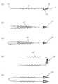
도 2는 본 발명의 일 실시예에 따른, 제1말단 및 제2말단을 가지는 봉합사에 있어서, 양쪽 말단부를 관통하는 연통구멍을 구비한 위가 잘린 원뿔 또는 각뿔형인 봉합사 지지체 또는 양쪽 말단부를 관통하는 연통구멍을 구비한 위가 잘린 원뿔 또는 각뿔형 이며 아래 말단부에 절개된 부위 또는 틈을 가지는 봉합체 지지체가 봉합사 지지체의 위 말단(양 말단 중에서 직경이 작은 쪽; 21)이 봉합사 지지체가 결합되는 봉합사의 말단(11, 제1말단)을 향하도록 상기 연통구멍을 통하여 상기 봉합사에 꿰어져 제1말단에 구비되고 다른 일말단(제2말단)에 바늘(30)을 구비한 봉합사를 나타낸 도면이다.Figure 2 is a suture having a first end and a second end, according to an embodiment of the present invention, the suture support having a communication cone or pyramidal cut through the both ends or through the end of the suture support or both ends Suture with a conical or pyramidal truncated conical or pyramid with communication holes and a suture support having a site or gap cut in the lower distal end of the suture support. It is a diagram showing the suture threaded to the suture through the communication hole to face the end (11, the first end) of the suture provided at the first end and the
봉합사의 표면에는 미늘이 봉합사의 종축과 이루는 각이 동일방향으로 경사지도록 형성된다. 봉합사의 표면에 형성되는 미늘은 상기 봉합사의 제2말단를 향하여 상기 봉합사의 종축-봉합사의 제2말단방향-미늘이 형성하는 각(θ1)이 예각을 이루도록 경사지게 형성된다. 이와 같이 미늘과 봉합사가 이루는 각이 봉합사 지지체가 구비되지 않는 봉합사의 제2말단을 향하여 뾰족한 형상을 하도록 미늘이 형성되어 있으면, 봉합사의 제2말단에 결합된 바늘로 봉합을 할 때는 봉합사가 매끄럽게 조직을 잘 통과하게 되나 봉합 후에 제2말단으로부터 바늘을 제거하여도 봉합사가 봉합방향과 반대로 이동하려 하면 버팀목처럼 지지하며 이동을 막아 줄 수 있다. 봉합이 끝나고 바늘을 잘라내어도 미늘에 의하여 봉합사가 빠지지 않으므로 매듭을 짓지 않아도 된다. 또한, 봉합사의 일 말단에 구비된 봉합사 지지체는 봉합이 풀리지 않도록 하는 매듭의 역할을 할 뿐만 아니라, 봉합이나 리프팅을 실시하면서 실을 잡아 당길 때 봉합체 지지체의 아래 말단에 형성된 절개된 부분 또는 벌어진 틈에 의하여 봉합체 지지체가 움직이지 않도록 위치가 단단하게 고정될 수 있다. 따라서, 리프팅 효과를 안정적이고 오래 지속되도록 한다.The surface of the suture is formed such that the angle formed by the barbs with the longitudinal axis of the suture is inclined in the same direction. The barb formed on the surface of the suture is formed to be inclined toward the second end of the suture so that the angle (θ1) formed by the longitudinal axis of the suture-the second end of the suture-the barb forms an acute angle. Thus, if the barb is formed to have a pointed shape toward the second end of the suture in which the suture is not provided with the suture support, the suture is smoothly organized when sutured with a needle coupled to the second end of the suture. If the suture tries to move in the opposite direction of the suture even if the needle is removed from the second end after suture, it can be supported like a crutch and prevent movement. When the stitches are finished and the needles are cut, the sutures are not pulled out by the barbs, so there is no need to make a knot. In addition, the suture support provided at one end of the suture not only serves as a knot to prevent the suture from loosening, but also a cut-out portion or a gap formed at the lower end of the suture support when the thread is pulled while performing suture or lifting. The position can be firmly fixed so that the suture support does not move. Thus, the lifting effect is made stable and long lasting.
본 발명의 일 실시예에 따르면, 미늘이 형성된 봉합사는 예를 들어 한 줄, 두 줄, 세 줄 또는 네 줄 이상 사용할 수 있으며 실의 굵기, 사용목적에 따라 적절히 그 수를 조절할 수 있으며, 각각의 봉합사는 단일사 또는 다중사가 꼬이거나 짜인 것일 수 있다. 이 때 미늘이 형성된 각각의 봉합사의 제1말단은 하나의 봉합사 지지체에 함께 꿰어질 수 있으며(도2의 b, c, e, f 참조), 또는 각 봉합사의 제1말단에 각각 별도의 봉합사 지지체를 가질 수 있다(도 2 의 d). 또한, 두 줄의 봉합사는 제2말단에서 하나의 바늘에 함께 결합될 수 있으며(도2의 b, c, d, e) 또는 각각의 제2말단에 별개의 바늘이 각각 결합될 수도 있다(도 2의 f).According to one embodiment of the present invention, the barbed sutures may be used, for example, one, two, three, or four or more lines, and the number of threads can be appropriately adjusted according to the thickness and purpose of use. Sutures may be twisted or woven into a single yarn or multiple yarns. At this time, the first end of each suture barbed can be stitched together in one suture support (see b, c, e, f of Figure 2), or each separate suture support at the first end of each suture It may have (d in FIG. 2). In addition, two rows of sutures may be coupled together to one needle at the second end (b, c, d, e of FIG. 2) or a separate needle may be respectively coupled to each second end (FIG. 2, f).
도 2의 b는 봉합사의 전반부와 후반부가 동일방향으로 경사지도록 미늘이 형성된 두 줄 이상의 실을 모아, 봉합사의 바늘이 결합되는 말단를 향하여 봉합사의 종축-봉합사의 바늘이 결합되는 말단방향-미늘이 형성하는 각(θ1)이 예각을 이루며 경사지게 배치되도록 봉합사의 한쪽 끝을 바늘에 결합시키고 반대쪽 끝 부부은 지지체에 결합시켜 제조한 예이다. 도 2의 c는, 다른 실시예로서, 봉합사에 형성된 미늘이 전반부와 후반부가 서로 반대 방향으로 경사지도록(예를 들어, 봉합사의 전반부는 미늘이 봉합사의 종축과 미늘이 이루는 각이 모두 90도 미만으로 봉합사의 앞말단을 향해 경사지도록 형성되고, 봉합사의 후반부는 미늘이 봉합사의 종축과 미늘이 이루는 각이 모두 90도 미만으로 봉합사의 뒷말단을 향해 경사지도록 형성) 형성된 한 줄 이상의 실을 반으로 접은 후 양 말단을 각각 지지체 및 바늘에 결합시켜 제조한 예이다.2b shows two or more rows of barbed threads having a barb inclined in the same direction in the first and second ends of the suture, and the longitudinal-barb is formed in which the suture longitudinal- suture needles are coupled toward the end where the suture needles are coupled. One end of the suture is coupled to the needle so that the angle (θ1) is inclined at an acute angle, and the opposite end couple is coupled to the support. FIG. 2C is another embodiment, in which the barbs formed in the sutures are inclined in opposite directions to each other (for example, the first half of the suture is less than 90 degrees in angle between the longitudinal axis of the suture and the barbs). And the second half of the suture is formed to be inclined toward the rear end of the suture by less than 90 degrees of both the longitudinal axis of the suture and the angle formed by the suture. After folding, both ends are bonded to the support and the needle, respectively.
도 3은, 본 발명의 일 실시예에 따른, 양쪽 말단부를 관통하는 연통구멍을 구비하고 위가 잘린 원뿔 또는 각뿔형인 봉합사 지지체 또는 양쪽 말단부를 관통하는 연통구멍을 구비한 위가 잘린 원뿔 또는 각뿔형이며 아래쪽 말단부에 절개된 부위 또는 틈을 가지는 봉합체 지지체가, 봉합사 지지체의 위 말단(21;양 말단 중에서 직경이 작은 쪽)이 봉합사의 제1말단(11)을 향하도록 상기 연통구멍을 통하여 상기 봉합사에 꿰어져 제1말단에 구비되고 제2말단(12)에 바늘이 구비되지 않은 상태로 사용되는 봉합사를 나타낸 도면이다. 상기 봉합사는 미늘이 구비될 수 있으며, 봉합사의 표면에 형성되는 미늘은 상기 봉합사의 제2말단를 향하여 상기 봉합사의 종축-봉합사의 제2말단-미늘이 형성하는 각(θ1)이 예각을 이루도록 경사지게 형성된다.3 is a truncated cone or pyramid having a communication hole through both ends and a suture support that is a truncated cone or pyramid or a communication hole through both ends, according to one embodiment of the invention. And a suture support having a site or a gap cut in the lower distal end thereof, through the communication hole such that the upper end 21 (the smaller diameter of both ends) of the suture support faces the
본 발명의 일 실시예에 따르면, 미늘이 형성된 봉합사는 예를 들어 한 줄, 두 줄, 세 줄 또는 네 줄 이상 사용할 수 있으며 실의 굵기, 사용목적에 따라 적절히 그 수를 조절할 수 있다. 두 줄 이상의 봉합사로 된 경우 각 봉합사가 하나의 봉합사 지지체의 연통구멍을 통과하여 함께 매듭이 지어지거나(도3의 b, c), 또는 한 줄의 봉합사가 지지체의 연통구멍을 통과하는 형태로 봉합사 지지체에 꿰어진다(도3의 d). 도 3의 c, d 및 e는 봉합사에 형성된 미늘이 전반부와 후반부가 서로 반대 방향으로 경사지도록 형성된 한 줄 이상의 실을 반으로 접은 후 한쪽 말단을 봉합사 지지체에 결합시켜 제조한 예이다. According to one embodiment of the present invention, the barbed sutures may be used, for example, one line, two lines, three lines or four or more lines, and the number thereof may be appropriately adjusted according to the thickness of the thread and the purpose of use. In the case of two or more sutures, each suture is knotted together through the communication hole of one suture support (b, c in FIG. 3), or the suture is formed in such a way that a suture passes through the communication hole of the support. It is sewn onto the support (FIG. 3 d). 3, c, d and e are examples prepared by folding one or more strings of barbs formed in the suture thread so that the first and second parts are inclined in opposite directions to each other and then connecting one end to the suture support.
미늘이 형성된 봉합사는 공개특허 제10-2008-39345호, 제10-2005-0108494호 및 등록실용신안공보 제20-320005호, 미국특허 제5931855호 등에 기재되어 있으며, 이들의 내용이 본 명세서에 도입된다. 미늘은 임의의 필요한 구성에 따라 섬유상에 배열될 수 있고, 본 발명의 기술분야에서 널리 공지된 것들을 포함하는 임의의 적절한 방법을 사용하여 형성될 수 있다. 이러한 방법들은 칼 또는 레이저, 프레스 성형에 의한 사출성형, 스탬핑, 절단을 포함할 수 있다. 필요한 수의 예각의 절단이 봉합사에 만들어 진다. 미늘의 크기는 본 발명의 기술분야의 상식의 범위에서 목적에 따라 적절히 조절할 수 있다. 예를 들어, 봉합사에 형성된 미늘의 깊이는 약 30-100 미크론 정도 일 수 있으며, 봉합사의 직경에 따라 조절될 수 있다. 봉합사 표면 위에 형성되는 미늘들 사이의 간격은 100 마이크론 내지 1mm, 또는 그 이상일 수 있다.The barbed sutures are described in Korean Patent Application Publication Nos. 10-2008-39345, 10-2005-0108494, and Utility Model Publication Nos. 20-320005, US Patent No. 5931855, and the like. Is introduced. The barbs may be arranged on the fibers according to any desired configuration and may be formed using any suitable method, including those well known in the art. Such methods may include injection molding, stamping, cutting by knife or laser, press molding. The required number of acute cuts are made in the suture. The size of the barb may be appropriately adjusted according to the purpose within the scope of common sense in the art. For example, the depth of the barbs formed in the suture may be about 30-100 microns, and may be adjusted according to the diameter of the suture. The spacing between the barbs formed on the suture surface may be between 100 microns and 1 mm, or more.
본 발명에서 사용되는 봉합사는 예를 들어 고분자 재료나 금속재료, 생물학적 재료 등 여러 가지 재료로 만들어 지는데, 예를 들어 폴리프로필렌 (polypropylene), 금, 스테인레스스틸, 티타늄, 나일론, 폴리비닐리덴플루오라이드 (polyvinyliden fluoride), 폴리에스터, 브레이디드실크 (braided silk) 등 흡수되지 않는(non-adsorbable) 재질로 만들 수 있고 또는 Polydioxanone (PDO, PDS)과 같은 흡수가능한(absorbable) 재질로 만들어 질 수 있으며, 이로 제한되는 것은 아니다. 또한, 본 발명에서 사용되는 봉합사는 단섬유 형태 또는 고인 봉합사 등의 형태 등으로 사용된다.The suture used in the present invention is made of various materials such as polymer materials, metal materials, biological materials, for example, polypropylene (gold), gold, stainless steel, titanium, nylon, polyvinylidene fluoride ( It can be made of non-adsorbable material such as polyvinyliden fluoride, polyester, braided silk, or made of absorbable material such as Polydioxanone (PDO, PDS). It is not limited. In addition, the suture used in the present invention is used in the form of a short fiber or a deceased suture.
본 발명의 일실시예에 따른 한 쪽 말단에 양쪽 말단부를 관통하는 연통구멍을 구비하고 위가 잘린 원뿔 또는 각뿔형인 봉합사 지지체 또는 양쪽 말단부를 관통하는 연통구멍을 구비한 위가 잘린 원뿔 또는 각뿔형이며 아래쪽 말단부에 절개된 부위 또는 틈을 가지는 봉합사 지지체를 구비한 봉합사를 사용하는 방법으로 예를 들어, 다음과 같은 단계를 포함할 수 있다. 1) 피부나 조직으로 봉합사 지지체를 원하는 위치에 위치시킬 수 있도록 조직을 바늘로 뚫고 속이 빈 긴 관(60)을 피부나 조직의 특정 위치로 밀어 넣는 단계(a), 2) 긴 관을 통하여 본 발명의 일 실시예에 따른 봉합사 지지체(20)를 구비한 봉합사(10)를 목적하는 위치로 봉합사 지지체가 도달할 수 있도록 넣어 주는 단계(b), 3) 피부 또는 조직 내의 긴 관을 통과한 봉합사 지지체를 외부에서 누르거나 가는 봉으로 움직이지 않게 고정시키고 긴 관만 외부로 제거하는 단계(c), 4) 상기 봉합사 지지체를 눌러 주며 봉합사를 잡아 당기면서 조직를 밀어주는 단계(d). 이 때 사용되는 봉합사는 일말단에 봉합사 지지체를 가지는 한 줄의 미늘이 형성된 봉합사를 하나 또는 복수개를 사용할 수 있으며, 또는 두 줄 이상의 미늘이 형성된 봉합사가 하나의 봉합사 지지체에 결합된 것을 사용할 수도 있다. 상기 방법에서 봉합사 지지체는 봉합이 풀리지 않도록 하는 매듭의 역할을 할 뿐만 아니라, 봉합이나 리프팅을 실시하면서 실을 잡아 당길 때 봉합사가 이동하지 않고 고정될 수 있도록 한다. 아래 말단에 형성된 절개된 부분 또는 벌어진 틈을 가지는 봉합사 지지체는 고정효과가 더 크다. 따라서, 리프팅 효과를 안정적이고 오래 지속되도록 한다. 봉합사 지지체가 결합되지 않은 봉합사의 제2말단를 향하여 봉합사의 종축-봉합사의 제2말단방향-미늘이 형성하는 각(θ1)이 예각을 이루도록 경사지게 미늘이 형성되어 있는 경우, 형성된 미늘은 봉합사표면과 이루는 각도에 의하여 봉합사가 리프팅의 반대 방향으로 빠지는 것을 막아 주며 조직이 당겨진 상태로 유지되도록 한다. 봉합사를 긴 관을 통과시켜 넣어 줄 때는 조직에 의한 저항이 없으므로 잘 통과하며, 긴 관을 제거하고 봉합사 지지체를 눌러주며 봉합사를 당기면서 조직을 밀어 줄 때도 미늘과 봉합사가 이루는 각이 예각이 되도록 형성된 미늘이 조직의 이동에 큰 영향을 주지 않지만, 조직이 반대방향으로 다시 되돌아 오려고 하면 미늘이 저항을 하게 된다.It is a truncated cone or pyramid having a communication hole penetrating both ends at one end and a suture support that is a truncated cone or pyramid or a communication hole penetrating both ends at one end according to an embodiment of the present invention. For example, a method of using a suture provided with a suture support having a site or a gap cut in the lower distal end may include the following steps. 1) penetrating the tissue with a needle to push the suture support to the desired position with the skin or tissue, and pushing the hollow long tube 60 into a specific position of the skin or tissue (a), 2) through the long tube Step (b) to put the suture support with the
본 발명은 일 실시예로, 본 발명에서 제공하는 봉합사로 시술을 용이하게 실시할 수 있도록 하는 장치를 제공한다. 본 발명에서 제공하는 장치에는 봉합사가 내장된 키트(키트 A) 및 봉합사를 조직 내에 정확하게 위치시켜 줄 수 있도록 하는 봉합사 위치 결정용 키트(키트 B)를 포함한다.In one embodiment, the present invention provides an apparatus for facilitating the procedure with a suture provided by the present invention. Apparatus provided in the present invention includes a suture kit (kit A) and a suture positioning kit (kit B) that allows the suture to be accurately positioned in the tissue.
봉합사가 내장된 키트(키트 A)는 양말단을 연통하는 구멍이 내부에 형성되어 있는 긴 관(70) 및 상기 긴 관에 내장된 봉합사를 포함하는데, 상기 봉합사는 제1말단 및 제2말단을 가지며 제1말단에 봉합사 지지체가 구비되어 있고, 상기 봉합사 지지체는 양쪽 말단부를 관통하는 연통구멍을 구비한 위가 잘린 원뿔 또는 각뿔형인 봉합사 지지체 또는 양쪽 말단부를 관통하는 연통구멍을 구비한 위가 잘린 원뿔 또는 각뿔형이며 아래 말단부에 절개된 부위 또는 틈을 가지고 있는 봉합체 지지체이며, 상기 봉합사 지지체는 봉합사 지지체의 위 말단이 봉합사의 제1말단을 향하도록 상기 연통구멍을 통하여 상기 봉합사에 꿰어져 제1말단에 구비되고, 상기 봉합사의 표면에는 미늘이 형성되되 상기 봉합사의 제2말단를 향하여 상기 봉합사의 종축-봉합사의 제2말단방향-미늘이 형성하는 각(θ1)이 예각을 이루도록 경사지게 형성된다. 키트 A는 양 말단이 연통된 긴 관에 본 특허출원에서 제공하는 봉합사 지지체가 구비되고 미늘이 형성된 봉합사를 삽입하여 제조되는데, 이 때 긴 관의 양 말단 중에서 조직 내부로 뚫고 들어가게 되는 말단 쪽으로 봉합사 지지체가 위치하도록 한다(도 4의 a). 봉합사 지지체는 긴 관의 내부에 내장되거나 또는 필요에 따라 긴 관 말단의 외부 또는 긴 관의 내부와 외부에 걸쳐 위치하도록 할 수 있다. 키트 A의 긴 관의 연통구멍의 직경은 내부에 봉합사를 수용할 수 있는 크기를 가지도록 하며, 목적에 따라 크기는 조절이 가능하다.Kit containing a suture (kit A) includes a
봉합사를 조직 내에 정확하게 위치시켜 줄 수 있도록 하는 봉합사 위치 결정용 키트(키트 B)는 양말단을 연통하는 구멍이 내부에 형성되어 있는 긴 관(80) 및 상기 긴 관의 연통구멍에 삽입되며 길이가 상기 긴 관의 길이보다 길고 한쪽에 신체 내부로 삽입가능한 선단을 가진 로드(rod; 90)를 포함한다(도 4의 b). 상기 로드는 피부나 조직을 뚫고 들어갈 수 있는 정도의 강도를 가진 재료로 만들어지며, 선단이 뭉툭하거나 둥근 모양을 가지면 조직의 손상을 최소화시킬 수 있다.The suture positioning kit (kit B), which allows the suture to be accurately positioned in the tissue, is inserted into the
키트 B의 긴 관는 키트 A의 긴 관보다 길이가 짧고, 키트A를 수용할 수 있도록 연통구멍의 직경이 키트 A의 긴 관보다 큰 것이 바람직하다. 상기 긴 관 및 로드는 우레탄 플라스틱, 금속 또는 조직을 뚫고 들어갈 수 있는 정도로 경도가 높고 인체에 무해한 재료이면 어떤 소재를 사용하여도 무방하다. 키트A 및 키트 B의 긴 관는 시술의 편의를 위하여 말단에 손잡이부가 구비될 수 있다.The long tube of the kit B is shorter than the long tube of the kit A, and the diameter of the communication hole is preferably larger than that of the kit A to accommodate the kit A. The long pipe and rod may be any material as long as the material is high enough to penetrate urethane plastic, metal or tissue and is harmless to human body. Long tubes of Kit A and Kit B may be provided with handles at the ends for convenience of the procedure.
도 4의 장치는 예를 들어, 다음과 같은 단계를 포함하는 방법으로 사용할 수 있다. 1) 봉합 또는 리프팅하려는 부위 또는 조직으로 키트 B를 밀어 넣는 단계, 2) 긴 관(80)은 그대로 두고 로드(90)만 제거하는 단계(b). 3)조직에 남겨진 긴 관(80) 속으로 키트 A를 밀어 넣는 단계(c) (이때 봉합사 지지체가 위치하고 있는 쪽을 조직의 안쪽으로 향하게 한다.), 4) 키트 A는 조직에 남겨둔 채 키트B의 긴 관(80)을 제거하는 단계(d), 5) 가는 봉(100)으로 봉합사 지지체를 키트A의 긴 관(70) 밖의 조직 속으로 밀어 넣는 단계(e), 6) 키트A의 긴 관(70) 및 가는 봉(100)을 제거하는 단계(f), 7) 봉합사를 당기며 피부(또는 조직의 외부)를 봉합사 지지체 쪽으로 밀어주는 단계(g). 필요할 경우 외부(예를 들어 피부)에서 눌러 봉합사 지지체가 움직이지 않도록 할 수도 있다.The apparatus of FIG. 4 can be used, for example, in a method comprising the following steps. 1) pushing kit B into the site or tissue to be sutured or lifted, 2) removing the
본 발명은 또한 본 발명에서 제공하는 봉합사로 시술을 용이하게 실시할 수 있도록 하는 다른 일 실시예의 키트를 제공한다 (도 5). 이 키트는 i) 점점 가늘어 지는 팁(101)의 형상으로 된 제1말단, 핸들(103)이 형성된 제2말단 및 제1말단 부근에 형성된 봉합사에 구비된 봉합사 지지체의 수납부(102)를 포함하며, 제1말단과 제2말단을 잇는 종축 방향으로 분리될 수 있는 속이 빈 긴 관(104) 및 ii) 상기 속이 빈 긴 관에 내장된 본 발명에서 제공하는 봉합사 지지체가 구비된 봉합사를 포함하는 것을 특징으로 한다. 도 5의 (a)는 봉합사 지지체가 구비된 봉합사가 내장된 속이 빈 관의 일실시예를 보여준다.The present invention also provides a kit of another embodiment to facilitate the procedure with the suture provided in the present invention (FIG. 5). The kit includes: i) a receiving
이때, 속이 빈 관의 제1말단이 끝은 막히거나 또는 제2말단과 연통된 구멍을 형성할 수 있다. 팁은 조직을 통과할 수 있는 정도의 강도를 가지는 재료를 사용하는 것이 바람직하며, 팁의 끝을 뭉툭하게 하면 조직의 손상을 줄일 수 있는 장점이 있다. 상기 속이 빈 긴 관에 형성되는 봉합사 지지체 수납부는 제2말단으로부터 형성되는 빈 공간의 연장으로서, 봉합사에 구비된 봉합사 지지체를 수용할 수 있는 공간이며, 수용되는 봉합사 지지체의 크기 및 개수 등에 따라 적절하게 모양과 크기를 조절할 수 있다 (도 5의 (b) 참조).At this time, the end of the first end of the hollow tube may be blocked or form a hole in communication with the second end. The tip is preferably made of a material having a strength enough to pass through the tissue, the blunt end of the tip has the advantage of reducing tissue damage. The suture supporter receiving portion formed in the hollow long tube is an extension of the empty space formed from the second end, and is a space for accommodating the suture support provided in the suture, and suitably according to the size and number of the suture support received. The shape and size can be adjusted (see FIG. 5B).
상기 속이 빈 관(104)은 도 5의 (c)에서 예시한 바와 같이 제1말단과 제2말단을 잇는 종축 방향으로 분리될 수 있으며, 분리된 관의 한 쪽(104a)의 위에 봉합사 지지체가 구비된 봉합사를 놓고 분리된 관의 나머지 한 쪽(104b)을 덮어 봉합사가 내장된 속이 빈 관을 제조할 수 있다. 이 때, 예를 들어 두 핸들(103a, 103b)이 만나는 부분의 한쪽에는 볼록한 부분(105), 다른 한 쪽에는 상기 볼록한 부분이 꼭 맞게 끼워질 수 있는 오목한 부분(106)을 형성시켜서 두 핸들 부분을 합칠 때 안정적으로 고정?결합되어 결과적으로 봉합사가 수납된 관이 안정적으로 유지될 수 있도록 할 수 있다(핸들의 위에서 본 모양을 나타낸 도 5의 (d) 참조). 그 외에 분리된 두 부분의 결합으로 형성되는 관이 시술 중 필요한 시기까지 안정적인 모양을 유지할 수 있는 다양한 조치를 취할 수 있다.The
봉합사가 수납된 관을 팁(101)쪽으로부터 봉합 또는 리프팅이 필요한 부위로 밀어 넣은 후, 관의 빈 공간을 통하여 가는 봉을 넣어 봉합사 지지체를 움직이지 않도록 하면서, 관을 분리하여 분리된 부분(104a, 104b)을 하나씩 제거하고, 가는 봉을 제거한 후, 봉합사를 당기며 피부(또는 조직의 외부)를 봉합사 지지체(20) 쪽으로 밀어주는 방법으로 시술을 할 수 있다.Push the suture containing tube from the
Claims (24)
Translated fromKorean상기 봉합사는 제1말단 및 제2말단을 가지며 제1말단에 봉합사 지지체가 구비되어 있고,
상기 봉합사 지지체는 위가 잘린 원뿔 또는 각뿔형의 모양이며 양쪽 말단부를 관통하는 연통구멍을 구비하고 있는 봉합사 지지체 또는 위가 잘린 원뿔 또는 각뿔형의 모양이며 양쪽 말단부를 관통하는 연통구멍을 구비하고 있고 양 말단 중에서 직경이 더 큰 쪽인 아래쪽의 말단부에 아래 말단으로부터 세로 방향으로 절개된 부위를 하나 이상 포함하거나 아래쪽 말단의 일부가 제거되어 말단부의 벽에 말단으로부터 형성된 하나 이상의 틈이 형성된 봉합사 지지체이며,
상기 봉합사 지지체는 봉합사 지지체의 위 말단이 봉합사의 제1말단을 향하도록 상기 연통구멍을 통하여 상기 봉합사에 꿰어져 제1말단에 구비되고,
상기 봉합사의 표면에는 미늘이 형성되되 상기 봉합사의 제2말단를 향하여 상기 봉합사의 종축-봉합사의 제2말단방향-미늘이 형성하는 각(θ1)이 예각을 이루도록 경사지게 형성되는 것을 특징으로 하는 봉합사가 내장된 키트.In the kit with a suture containing a long tube and a suture embedded in the long tube is formed therein a hole communicating with the sock end,
The suture has a first end and a second end and is provided with a suture support at the first end,
The suture support is in the shape of a conical or pyramid with a cut off stomach and has a communication hole penetrating both ends and has a suture support or a conical or pyramidal shape with a cut through the both ends and a communication hole penetrating both ends. A suture support comprising one or more sections cut longitudinally from the lower end to the lower distal end of the larger end, or a portion of the lower end being removed to form one or more gaps formed from the ends in the wall of the distal end;
The suture supporter is provided at the first end by being stitched to the suture through the communication hole so that the upper end of the suture support toward the first end of the suture,
A suture is formed on the surface of the suture, and the suture longitudinal direction is formed such that the angle (θ1) formed by the suture longitudinal longitudinal direction of the suture-the second end direction of the suture is formed to be inclined at an acute angle. Kit.
i) 양말단을 연통하는 구멍이 내부에 형성되어 있는 긴 관 및 ii) 상기 긴 관의 연통구멍에 삽입되며 길이가 상기 관의 길이보다 길고 한쪽에 신체 내부로 삽입가능한 선단을 가진 로드(rod)를 포함하는 키트(키트 B)를 포함하는 수술용 장치.The kit containing the suture of claim 20 (kit A),
i) a long tube having a hole communicating with the sock end therein; and ii) a rod having a tip inserted into the communication hole of the long tube and having a length longer than the length of the tube and inserted into the body on one side. Surgical device comprising a kit comprising (kit B).
ii) 위가 잘린 원뿔 또는 각뿔형의 모양이며 양쪽 말단부를 관통하는 연통구멍을 구비하고 있는 봉합사 지지체 또는 위가 잘린 원뿔 또는 각뿔형의 모양이며 양쪽 말단부를 관통하는 연통구멍을 구비하고 있고 양 말단 중에서 직경이 더 큰 쪽인 아래쪽의 말단부에 아래 말단으로부터 세로 방향으로 절개된 부위를 하나 이상 포함하거나 아래쪽 말단의 일부가 제거되어 말단부의 벽에 말단으로부터 형성된 하나 이상의 틈이 형성된 봉합사 지지체가 봉합사의 제1말단에 구비되며, 이 때 봉합사 지지체는 위쪽 말단(양 말단 중에서 직경이 작은 쪽)이 봉합사의 제1말단을 향하도록 상기 연통구멍을 통하여 상기 봉합사에 꿰어져 있는 것을 특징으로 하는 봉합사를 포함하는 수술용 키트.i) a first end in the shape of a tapering tip which may be blunt, a second end having a handle, and a receiving portion of a suture support provided in a suture formed near the first end, the first end and the first end A hollow tube for suture internal organs that can be separated in a longitudinal axis connecting two ends;
ii) a suture support having a conical or pyramidal cut off stomach and having communication holes penetrating both ends, or a conical or pyramidal cut off stomach having communication holes penetrating both ends; The first end of the suture is a suture support comprising one or more sections cut longitudinally from the lower end to the larger distal end of the lower end or a portion of the lower end removed so that at least one gap formed from the end is formed in the wall of the distal end. In this case, the suture support is a surgical including a suture is characterized in that the suture is stitched through the communication hole so that the upper end (the smaller diameter of both ends) toward the first end of the suture. Kit.
Priority Applications (30)
| Application Number | Priority Date | Filing Date | Title |
|---|---|---|---|
| KR1020110143929AKR101185583B1 (en) | 2011-12-27 | 2011-12-27 | A suture which need not be knotted and a kit comprising the suture |
| CN201280064950.XACN104023651B (en) | 2011-12-27 | 2012-12-24 | suture |
| NZ626645ANZ626645B2 (en) | 2011-12-27 | 2012-12-24 | Knotless suture, and kit containing same |
| BR112014015874-6ABR112014015874B1 (en) | 2011-12-27 | 2012-12-24 | SUTURE SET, METHOD OF MANUFACTURING A SUTURE SET, OPERATING KIT AND OPERATING DEVICE |
| JP2014549981AJP2015504722A (en) | 2011-12-27 | 2012-12-24 | A suture that does not require a knot work and a kit including the suture |
| MX2014007902AMX2014007902A (en) | 2011-12-27 | 2012-12-24 | Knotless suture, and kit containing same. |
| EP12862308.9AEP2799016B1 (en) | 2011-12-27 | 2012-12-24 | Knotless suture, and kit containing same |
| SG11201403580TASG11201403580TA (en) | 2011-12-27 | 2012-12-24 | Knotless suture, and kit containing same |
| SG10201606722RASG10201606722RA (en) | 2011-12-27 | 2012-12-24 | Knotless Suture, And Kit Containing Same |
| RU2014127703ARU2616762C2 (en) | 2011-12-27 | 2012-12-24 | Suturing thread for angle-free suture and set, which includes suturing thread |
| HK15102063.1AHK1202789B (en) | 2011-12-27 | 2012-12-24 | Suture |
| AU2012360392AAU2012360392B2 (en) | 2011-12-27 | 2012-12-24 | Knotless suture, and kit containing same |
| PCT/KR2012/011361WO2013100513A1 (en) | 2011-12-27 | 2012-12-24 | Knotless suture, and kit containing same |
| US14/368,997US9480473B2 (en) | 2011-12-27 | 2012-12-24 | Knotless suture, and kit containing same |
| CA2861753ACA2861753C (en) | 2011-12-27 | 2012-12-24 | Knotless suture, and kit containing same |
| MYPI2014001915AMY174291A (en) | 2011-12-27 | 2012-12-24 | Knotless suture, and kit containing same |
| TW101150242ATWI625112B (en) | 2011-12-27 | 2012-12-26 | Suture and method of manufacturing the same, kitequipped with suture, operation device, and operation kit with suture |
| IL233397AIL233397A0 (en) | 2011-12-27 | 2014-06-26 | Knotless suture, and kit containing same |
| PH12014501479APH12014501479A1 (en) | 2011-12-27 | 2014-06-26 | Knotless suture, and kit containing same |
| ZA2014/05036AZA201405036B (en) | 2011-12-27 | 2014-07-10 | Knotless suture, and kit containing same |
| IN1512KON2014IN2014KN01512A (en) | 2011-12-27 | 2014-07-17 | |
| JP2015241510AJP5959710B2 (en) | 2011-12-27 | 2015-12-10 | A suture that does not require a knot work and a kit including the suture |
| JP2016122504AJP5981674B1 (en) | 2011-12-27 | 2016-06-21 | A suture that does not require a knot work and a kit including the suture |
| JP2016148772AJP6339639B2 (en) | 2011-12-27 | 2016-07-28 | A suture that does not require a knot work and a kit including the suture |
| US15/340,784US9924937B2 (en) | 2011-12-27 | 2016-11-01 | Knotless suture, and kit containing same |
| US15/897,086US11103232B2 (en) | 2011-12-27 | 2018-02-14 | Knotless suture, and kit containing same |
| JP2018091563AJP6410980B2 (en) | 2011-12-27 | 2018-05-10 | A suture that does not require a knot work and a kit including the suture |
| JP2018178273AJP6763923B2 (en) | 2011-12-27 | 2018-09-25 | Sutures that do not require knotting and kits containing them |
| JP2020003171AJP6705951B2 (en) | 2011-12-27 | 2020-01-10 | Suture |
| JP2020085335AJP2020124597A (en) | 2011-12-27 | 2020-05-14 | Suture |
Applications Claiming Priority (1)
| Application Number | Priority Date | Filing Date | Title |
|---|---|---|---|
| KR1020110143929AKR101185583B1 (en) | 2011-12-27 | 2011-12-27 | A suture which need not be knotted and a kit comprising the suture |
Publications (1)
| Publication Number | Publication Date |
|---|---|
| KR101185583B1true KR101185583B1 (en) | 2012-09-24 |
Family
ID=47114059
Family Applications (1)
| Application Number | Title | Priority Date | Filing Date |
|---|---|---|---|
| KR1020110143929AActiveKR101185583B1 (en) | 2011-12-27 | 2011-12-27 | A suture which need not be knotted and a kit comprising the suture |
Country Status (18)
| Country | Link |
|---|---|
| US (3) | US9480473B2 (en) |
| EP (1) | EP2799016B1 (en) |
| JP (8) | JP2015504722A (en) |
| KR (1) | KR101185583B1 (en) |
| CN (1) | CN104023651B (en) |
| AU (1) | AU2012360392B2 (en) |
| BR (1) | BR112014015874B1 (en) |
| CA (1) | CA2861753C (en) |
| IL (1) | IL233397A0 (en) |
| IN (1) | IN2014KN01512A (en) |
| MX (1) | MX2014007902A (en) |
| MY (1) | MY174291A (en) |
| PH (1) | PH12014501479A1 (en) |
| RU (1) | RU2616762C2 (en) |
| SG (2) | SG10201606722RA (en) |
| TW (1) | TWI625112B (en) |
| WO (1) | WO2013100513A1 (en) |
| ZA (1) | ZA201405036B (en) |
Cited By (18)
| Publication number | Priority date | Publication date | Assignee | Title |
|---|---|---|---|---|
| KR101358341B1 (en) | 2013-10-08 | 2014-02-06 | 배승주 | Lifting unit for removing wrinkle |
| WO2014088353A1 (en)* | 2012-12-05 | 2014-06-12 | 주식회사 존제이콥스메디칼 | Apparatus for inserting surgical thread, and surgical procedure kit for inserting surgical thread comprising same |
| KR101452340B1 (en)* | 2011-12-16 | 2014-10-21 | 주식회사 삼양바이오팜 | A surgical suture |
| KR101490613B1 (en) | 2013-08-06 | 2015-02-11 | 박용호 | Plastic and cosmetic surgical device for physical lifting |
| WO2015083864A1 (en)* | 2013-12-06 | 2015-06-11 | 주식회사 와이제이콥스메디칼 | Apparatus for inserting medical tube and surgical procedure kit for inserting medical tube, having same |
| KR200479054Y1 (en)* | 2014-03-10 | 2015-12-14 | 양소연 | Medical Thread with Extensible Part |
| KR101642962B1 (en) | 2015-11-05 | 2016-07-26 | (주)제이월드 | Stitching fiber and process for manufacturing the same |
| KR20160107580A (en) | 2015-03-04 | 2016-09-19 | (주)제이월드 | The kit which using a stitching fiber and method thereof |
| US9480473B2 (en) | 2011-12-27 | 2016-11-01 | Y.Jacobs Medical Inc. | Knotless suture, and kit containing same |
| KR20160133862A (en) | 2015-05-13 | 2016-11-23 | 김대중 | apparatus of manufacturing surgical thread |
| KR101781268B1 (en)* | 2015-10-15 | 2017-09-26 | 박래경 | Medical Suture with Cogs and a manufacturing apparatus |
| US9808234B2 (en) | 2011-03-07 | 2017-11-07 | Y. Jacobs Medical Inc. | Suture thread |
| US10178990B2 (en) | 2012-12-05 | 2019-01-15 | Y. Jacobs Medical Inc. | Apparatus for inserting surgical thread, and surgical procedure kit for inserting surgical thread comprising same |
| WO2019221560A1 (en)* | 2018-05-18 | 2019-11-21 | (주)제이월드 | Medical suture and medical suture kit |
| KR20190131991A (en)* | 2018-05-18 | 2019-11-27 | (주)제이월드 | Suture kit |
| WO2019245319A1 (en)* | 2018-06-22 | 2019-12-26 | 주식회사 와이제이콥스메디칼 | Medical thread device |
| KR102066551B1 (en)* | 2019-09-09 | 2020-01-15 | 이은영 | suture with multy end loop |
| KR20230126870A (en) | 2022-02-24 | 2023-08-31 | 한길현 | Thread for lifting |
Families Citing this family (23)
| Publication number | Priority date | Publication date | Assignee | Title |
|---|---|---|---|---|
| EP1667586A1 (en) | 2003-09-15 | 2006-06-14 | Abbott Laboratories | Suture locking device and methods |
| US9149265B2 (en) | 2011-02-26 | 2015-10-06 | Abbott Cardiovascular Systems, Inc. | Hinged tissue support device |
| US9055932B2 (en) | 2011-08-26 | 2015-06-16 | Abbott Cardiovascular Systems, Inc. | Suture fastener combination device |
| US9138214B2 (en)* | 2012-03-02 | 2015-09-22 | Abbott Cardiovascular Systems, Inc. | Suture securing systems, devices and methods |
| US9486132B2 (en) | 2013-01-17 | 2016-11-08 | Abbott Cardiovascular Systems, Inc. | Access device for accessing tissue |
| US10028762B1 (en) | 2013-10-14 | 2018-07-24 | Percutaneous Cosmetic Devices LLC | Method of cutting soft tissue under facial skin |
| WO2015137873A1 (en)* | 2014-03-14 | 2015-09-17 | I Support Pte. Ltd. | A system for cosmetic enhancement |
| MY184035A (en)* | 2015-01-16 | 2021-03-17 | Racer Tech Pte Ltd | Method and apparatus for forming barbed sutures |
| WO2016148647A1 (en)* | 2015-03-13 | 2016-09-22 | I Support Pte. Ltd. | Anchor and suture for a suture assembly |
| JP6709618B2 (en)* | 2015-11-20 | 2020-06-17 | 医療法人社団翔友会 | Cosmetic thread, indwelling member, cosmetic instrument |
| SG10201606822SA (en)* | 2016-08-16 | 2018-03-28 | I Support Pte Ltd | Anchor and suture assembly |
| KR101825878B1 (en) | 2017-05-12 | 2018-02-06 | 장철호 | Needle apparatus for reposition surgery of orbital fat |
| US10524776B2 (en)* | 2016-11-08 | 2020-01-07 | Arthrex, Inc. | Soft suture anchor assembly with barbed suture and attached tissue fixation disk |
| CA3049920A1 (en)* | 2017-08-17 | 2019-02-21 | Smart Sutures, Llc | Curled suture device apparatus and method |
| US10624631B1 (en) | 2017-11-13 | 2020-04-21 | Simon B. Rayhanabad | Surgical suture and method of suturing |
| KR101878258B1 (en)* | 2018-01-11 | 2018-08-17 | 주식회사 오브이월드 | Medical suture material insertion tool |
| CN108784766A (en)* | 2018-07-05 | 2018-11-13 | 义乌美伦医疗科技有限公司 | A kind of band tooth pipe is outstanding to carry line |
| CN108852439B (en)* | 2018-07-27 | 2024-09-13 | 谭雄进 | Suture line tissue fixing device |
| CN109864835B (en)* | 2019-04-15 | 2024-06-11 | 童妍(上海)医疗器械有限公司 | Suture line, suture device and application of suture line |
| US11439383B2 (en) | 2019-08-20 | 2022-09-13 | Abbott Cardiovascular Systems, Inc. | Self locking suture and self locking suture mediated closure device |
| CA3153882A1 (en)* | 2019-10-31 | 2021-05-06 | Ho Sung Lee | Medical suture and method for producing same |
| US12409021B2 (en)* | 2022-08-04 | 2025-09-09 | Dina BenDavid | Inferior-to-superior deep tissue thread-lift using polydioxanone threads |
| WO2025117671A1 (en)* | 2023-11-29 | 2025-06-05 | Cedars-Sinai Medical Center | Suture implant and methods of using a suture implant |
Citations (2)
| Publication number | Priority date | Publication date | Assignee | Title |
|---|---|---|---|---|
| JP2754067B2 (en) | 1989-01-17 | 1998-05-20 | 日本ゼオン株式会社 | Medical body wall hole plugging jig |
| US20060135996A1 (en) | 1998-12-30 | 2006-06-22 | Schwartz Herbert E | Suture locking device |
Family Cites Families (159)
| Publication number | Priority date | Publication date | Assignee | Title |
|---|---|---|---|---|
| US3123077A (en) | 1964-03-03 | Surgical suture | ||
| SU100121A1 (en) | 1952-01-10 | 1954-11-30 | Б.Л. Виленский | Device for changing the direction of rotation of the drive shaft of the working body |
| GB1091282A (en) | 1963-07-09 | 1967-11-15 | Nat Res Dev | Sutures |
| US3981307A (en)* | 1974-07-01 | 1976-09-21 | Ethicon, Inc. | Thermal attachment of surgical sutures to needles |
| SU700121A1 (en)* | 1978-06-23 | 1979-11-30 | Челябинский медицинский институт | Apparatus for driving tubular prosthesis |
| DE3223153C1 (en) | 1982-06-22 | 1983-08-11 | B. Braun Melsungen Ag, 3508 Melsungen | Medical needle and thread combination |
| SU1178420A1 (en) | 1984-02-14 | 1985-09-15 | Донецкий медицинский институт им.М.Горького | Surgical needle |
| US4822904A (en) | 1985-12-12 | 1989-04-18 | Ethyl Corporation | Perfluoroalkylation process |
| KR950000058B1 (en) | 1986-06-12 | 1995-01-09 | 가부시끼가이샤 뮤텍크 | Suturing needle with suture and method of producing the same |
| SU1360705A1 (en) | 1986-07-18 | 1987-12-23 | Кемеровский государственный медицинский институт | Arrangement for making subarachnoid hemorrhage |
| US4744364A (en) | 1987-02-17 | 1988-05-17 | Intravascular Surgical Instruments, Inc. | Device for sealing percutaneous puncture in a vessel |
| DE3884743T2 (en) | 1987-10-30 | 1994-01-27 | Howmedica | Device for restoring a tendon or ligament. |
| JPH01317430A (en) | 1988-06-18 | 1989-12-22 | Keisei Ika Kogyo Kk | Device for assembling surgical needle for operation |
| US5053046A (en) | 1988-08-22 | 1991-10-01 | Woodrow W. Janese | Dural sealing needle and method of use |
| JPH0641535Y2 (en) | 1988-09-22 | 1994-11-02 | 富士写真光機株式会社 | Internal diagnosis / treatment device |
| FR2641692A1 (en) | 1989-01-17 | 1990-07-20 | Nippon Zeon Co | Plug for closing an opening for a medical application, and device for the closure plug making use thereof |
| US5053047A (en) | 1989-05-16 | 1991-10-01 | Inbae Yoon | Suture devices particularly useful in endoscopic surgery and methods of suturing |
| US4932962A (en) | 1989-05-16 | 1990-06-12 | Inbae Yoon | Suture devices particularly useful in endoscopic surgery and methods of suturing |
| US5080667A (en) | 1989-11-13 | 1992-01-14 | Ethicon, Inc. | Sterile surgical needle-suture combination |
| US5269809A (en) | 1990-07-02 | 1993-12-14 | American Cyanamid Company | Locking mechanism for use with a slotted suture anchor |
| US5224946A (en) | 1990-07-02 | 1993-07-06 | American Cyanamid Company | Bone anchor and method of anchoring a suture to a bone |
| US5041129A (en) | 1990-07-02 | 1991-08-20 | Acufex Microsurgical, Inc. | Slotted suture anchor and method of anchoring a suture |
| US5259846A (en) | 1991-01-07 | 1993-11-09 | United States Surgical Corporation | Loop threaded combined surgical needle-suture device |
| JPH04307050A (en) | 1991-01-17 | 1992-10-29 | Olympus Optical Co Ltd | Aspiration biopsy apparatus |
| US5224955A (en) | 1991-08-15 | 1993-07-06 | American Cyanamid Company | Surgical needle-suture combination and apparatus and method for attaching the same |
| US5236443A (en) | 1992-05-21 | 1993-08-17 | Sidney Sontag | Suturing assembly and method |
| US5207694A (en) | 1992-06-18 | 1993-05-04 | Surgical Invent Ab | Method for performing a surgical occlusion, and kit and applicator for carrying out the method |
| US5306294A (en) | 1992-08-05 | 1994-04-26 | Ultrasonic Sensing And Monitoring Systems, Inc. | Stent construction of rolled configuration |
| US6241747B1 (en)* | 1993-05-03 | 2001-06-05 | Quill Medical, Inc. | Barbed Bodily tissue connector |
| US5500000A (en) | 1993-07-01 | 1996-03-19 | United States Surgical Corporation | Soft tissue repair system and method |
| JP3419869B2 (en) | 1993-12-28 | 2003-06-23 | オリンパス光学工業株式会社 | Medical equipment |
| US5486197A (en)* | 1994-03-24 | 1996-01-23 | Ethicon, Inc. | Two-piece suture anchor with barbs |
| JP3587571B2 (en) | 1994-11-21 | 2004-11-10 | オリンパス株式会社 | Medical suture device |
| US5643295A (en) | 1994-12-29 | 1997-07-01 | Yoon; Inbae | Methods and apparatus for suturing tissue |
| US5571139A (en)* | 1995-05-19 | 1996-11-05 | Jenkins, Jr.; Joseph R. | Bidirectional suture anchor |
| US5626614A (en) | 1995-12-22 | 1997-05-06 | Applied Medical Resources Corporation | T-anchor suturing device and method for using same |
| US5683417A (en) | 1996-08-14 | 1997-11-04 | Cooper; William I. | Suture and method for endoscopic surgery |
| US5718717A (en)* | 1996-08-19 | 1998-02-17 | Bonutti; Peter M. | Suture anchor |
| JP3073713B2 (en) | 1997-01-17 | 2000-08-07 | ミサワ医科工業株式会社 | Indwelling needle set |
| US5741299A (en) | 1997-03-05 | 1998-04-21 | Rudt; Louis L. | Puncture-proof suture needle assembly |
| JP3835882B2 (en) | 1997-03-31 | 2006-10-18 | テルモ株式会社 | Indwelling needle assembly |
| US5931855A (en) | 1997-05-21 | 1999-08-03 | Frank Hoffman | Surgical methods using one-way suture |
| US5814051A (en)* | 1997-06-06 | 1998-09-29 | Mitex Surgical Products, Inc. | Suture anchor insertion system |
| JP2000202029A (en) | 1999-01-11 | 2000-07-25 | Misawa Ika Kogyo Kk | Method and apparatus for manufacturing indwelling needle |
| US6045573A (en) | 1999-01-21 | 2000-04-04 | Ethicon, Inc. | Suture anchor having multiple sutures |
| US9521999B2 (en)* | 2005-09-13 | 2016-12-20 | Arthrex, Inc. | Fully-threaded bioabsorbable suture anchor |
| RU2157159C1 (en)* | 1999-04-26 | 2000-10-10 | Тарутта Елена Петровна | Combined transplant for making scleroplastic repair |
| JP3069906U (en)* | 1999-12-22 | 2000-07-04 | 株式会社秋山製作所 | Suture needle with surgical needle |
| US6652571B1 (en)* | 2000-01-31 | 2003-11-25 | Scimed Life Systems, Inc. | Braided, branched, implantable device and processes for manufacture thereof |
| US6939326B1 (en)* | 2000-10-24 | 2005-09-06 | Vivek Thappa | Closed-end infusion catheter with an introducer and a method for using the same |
| US20020188170A1 (en)* | 2001-04-27 | 2002-12-12 | Santamore William P. | Prevention of myocardial infarction induced ventricular expansion and remodeling |
| FR2826253B1 (en) | 2001-06-21 | 2004-03-12 | Sofradim Production | ASSEMBLY COMPRISING A FASTENING ATTACHMENT FOR MEDICAL USE AND A DEVICE FOR THE POSITIONING OF THIS ATTACHMENT |
| US20020198544A1 (en) | 2001-06-22 | 2002-12-26 | Renan Uflacker | Percutaneous facelift device |
| AU2002320187A1 (en) | 2001-06-29 | 2003-03-03 | A.B. Korkor Medical, Inc. | Catheter introducer having an expandable tip |
| US7056331B2 (en)* | 2001-06-29 | 2006-06-06 | Quill Medical, Inc. | Suture method |
| GB0116247D0 (en)* | 2001-07-04 | 2001-08-29 | Univ Loughborough | Surgical techniques and devices |
| US20030149447A1 (en) | 2002-02-01 | 2003-08-07 | Morency Steven David | Barbed surgical suture |
| KR200287634Y1 (en) | 2002-06-07 | 2002-08-30 | 박영엽 | Stitching fiber insertion device for muscle strengthening |
| KR100473108B1 (en) | 2002-06-07 | 2005-03-08 | 박영엽 | Stitching fiber insertion device for muscle strengthening |
| JP2004041492A (en) | 2002-07-12 | 2004-02-12 | Scitec Kk | Medical needle |
| JP2004057516A (en) | 2002-07-29 | 2004-02-26 | Terumo Corp | Double needle assembly |
| US6773450B2 (en) | 2002-08-09 | 2004-08-10 | Quill Medical, Inc. | Suture anchor and method |
| JP2004073403A (en) | 2002-08-14 | 2004-03-11 | Terumo Corp | Indwelling needle assembly |
| US20040088003A1 (en) | 2002-09-30 | 2004-05-06 | Leung Jeffrey C. | Barbed suture in combination with surgical needle |
| JP3862167B2 (en) | 2002-10-04 | 2006-12-27 | 白壁 征夫 | Cheek fat traction tool |
| US7517357B2 (en) | 2003-01-09 | 2009-04-14 | Linvatec Biomaterials | Knotless suture anchor |
| KR200320005Y1 (en) | 2003-03-10 | 2003-07-16 | 이원석 | Thorny Sutures |
| EP1667586A1 (en) | 2003-09-15 | 2006-06-14 | Abbott Laboratories | Suture locking device and methods |
| US7666203B2 (en) | 2003-11-06 | 2010-02-23 | Nmt Medical, Inc. | Transseptal puncture apparatus |
| US7357810B2 (en) | 2003-12-18 | 2008-04-15 | Ethicon, Inc. | High strength suture with absorbable core and suture anchor combination |
| US7329271B2 (en) | 2003-12-18 | 2008-02-12 | Ethicon, Inc. | High strength suture with absorbable core |
| WO2005072402A2 (en) | 2004-01-29 | 2005-08-11 | Cannuflow, Inc. | Atraumatic arthroscopic instrument sheath |
| US7513904B2 (en) | 2004-03-15 | 2009-04-07 | Marlen Andreevich Sulamanidze | Surgical thread and cosmetic surgery method |
| WO2005096955A1 (en)* | 2004-04-07 | 2005-10-20 | Tze Liang Woffles Wu | Surgical thread |
| US7367980B2 (en) | 2004-04-28 | 2008-05-06 | Boston Scientific Scimed, Inc. | Introducer sheath stabilizer |
| KR20050108494A (en) | 2004-05-12 | 2005-11-17 | 김영복 | Surgical thread includes protrusions for plastic surgery operations |
| US10548592B2 (en) | 2004-05-14 | 2020-02-04 | Ethicon, Inc. | Suture methods and devices |
| US7582105B2 (en) | 2004-06-30 | 2009-09-01 | Silhouette Lift Societad Limitada | Suture for wound closure, tissue approximation, tissue support, suspension and/or fixation |
| US7468068B2 (en)* | 2004-06-30 | 2008-12-23 | Alwin Kolster | Suture for wound closure, tissue approximation, tissue support, suspension and/or fixation |
| JP4670037B2 (en) | 2004-07-12 | 2011-04-13 | 国立大学法人島根大学 | Surgical suture |
| JP5393980B2 (en)* | 2004-09-28 | 2014-01-22 | サージカル ソリューションズ リミテッド ライアビリティ カンパニー | Suture anchor |
| JP2006288755A (en) | 2005-04-11 | 2006-10-26 | Olympus Medical Systems Corp | Medical treatment equipment |
| US7766816B2 (en)* | 2005-06-09 | 2010-08-03 | Chf Technologies, Inc. | Method and apparatus for closing off a portion of a heart ventricle |
| EP1909655A2 (en)* | 2005-06-20 | 2008-04-16 | Sutura, Inc. | Method and apparatus for applying a knot to a suture |
| US8663277B2 (en) | 2005-06-29 | 2014-03-04 | Ethicon, Inc. | Braided barbed suture |
| US8702753B2 (en) | 2005-09-28 | 2014-04-22 | Olympus Medical Systems Corp. | Method for suturing perforation and suture instrument |
| GB0524360D0 (en) | 2005-11-30 | 2006-01-04 | Biocomposites Ltd | Suture anchor |
| JP4885979B2 (en)* | 2005-12-22 | 2012-02-29 | エス.ウェスト ジュニア ヒュー | Bone anchor used to attach soft tissue to bone |
| WO2007098212A2 (en)* | 2006-02-18 | 2007-08-30 | Amir Belson | Endoscopic suturing devices |
| EP1832238A3 (en) | 2006-03-07 | 2008-03-26 | Arthrex, Inc. | Tapered suture |
| KR100761921B1 (en) | 2006-03-13 | 2007-10-04 | 양현진 | Bio-insertion thread used in anti-compression multifibroadhesion for bio soft tissue extension and tool for inserting it into living body |
| US8192462B2 (en) | 2006-05-16 | 2012-06-05 | Marlen Andreevich Sulamanidze | Surgical suture material and method for the application thereof |
| EA200970189A1 (en)* | 2006-08-09 | 2009-08-28 | Смитклайн Бичам Корпорейшн | Pyrrolidinonanilines as modulators of progesterone receptors |
| US8758367B2 (en) | 2006-09-05 | 2014-06-24 | Smith & Nephew, Inc. | Anchor delivery system |
| BRPI0718156A2 (en) | 2006-10-26 | 2013-11-26 | Ams Res Corp | INSERT TOOL AND METHOD FOR PREPARING A SURGICAL TREATMENT SET. |
| US8167906B2 (en)* | 2006-11-01 | 2012-05-01 | Depuy Mitek, Inc. | Suture anchor with pulley |
| US8353931B2 (en) | 2006-11-02 | 2013-01-15 | Covidien Lp | Long term bioabsorbable barbed sutures |
| US20080132943A1 (en) | 2006-12-05 | 2008-06-05 | Nicholas Maiorino | Knotless wound closure device |
| US20080195147A1 (en) | 2007-02-09 | 2008-08-14 | Tyco Healthcare Group Lp | Surface eroding barbed sutures |
| JP5382938B2 (en) | 2007-02-20 | 2014-01-08 | コヴィディエン リミテッド パートナーシップ | Surgical instrument having an annular puncture device |
| ATE485858T1 (en) | 2007-03-14 | 2010-11-15 | Hoffmann La Roche | INSERTION HEAD FOR MEDICAL OR PHARMACEUTICAL APPLICATIONS |
| US20080281357A1 (en) | 2007-05-09 | 2008-11-13 | An-Min Jason Sung | Looped tissue-grasping device |
| US8157816B2 (en) | 2007-08-31 | 2012-04-17 | Kimberly-Clark Worldwide, Inc. | Gastropexy kit |
| US8771314B2 (en) | 2007-09-28 | 2014-07-08 | Ethicon, Inc. | Surgical anchor device |
| US8491455B2 (en) | 2007-10-03 | 2013-07-23 | Bioventrix, Inc. | Treating dysfunctional cardiac tissue |
| US8236013B2 (en) | 2007-10-19 | 2012-08-07 | Boston Scientific Scimed, Inc. | Apparatus for placing medical implants |
| US20090112259A1 (en) | 2007-10-31 | 2009-04-30 | Angiotech Pharmaceuticals, Inc. | Recombinant expressed bioadsorbable polyhydroxyalkonate monofilament and multi-filaments self-retaining sutures |
| NZ586548A (en) | 2008-01-14 | 2012-07-27 | Custom Med Applications Inc | Flexible spinal needle assembly with an internal flow element configured to avoid kinking or restriction of the needle |
| ES2706295T3 (en)* | 2008-02-21 | 2019-03-28 | Ethicon Llc | Method and apparatus for raising retainers in self-retaining sutures |
| KR100970453B1 (en) | 2008-03-28 | 2010-07-16 | 주식회사 덕우메디칼 | Urological catheter |
| US9034011B2 (en) | 2008-04-01 | 2015-05-19 | Covidien Lp | Anchoring device |
| US10376261B2 (en)* | 2008-04-01 | 2019-08-13 | Covidien Lp | Anchoring suture |
| US9358002B2 (en) | 2008-04-01 | 2016-06-07 | Covidien Lp | Anchoring device |
| US20090259251A1 (en) | 2008-04-11 | 2009-10-15 | Cohen Matthew D | Loop suture |
| US7967841B2 (en) | 2008-06-02 | 2011-06-28 | Ethicon, Inc. | Methods for using looped tissue-grasping devices |
| CN201216619Y (en) | 2008-07-22 | 2009-04-08 | 刘忠臣 | Medical stitching device |
| KR200451570Y1 (en) | 2008-09-01 | 2010-12-22 | 김동석 | Wrinkle Removal Needle Set |
| WO2010028324A2 (en) | 2008-09-08 | 2010-03-11 | Revolutionary Surgical Device, Llc | Knotless suture anchors |
| EP2352435B1 (en) | 2008-10-31 | 2019-11-27 | Sinclair Pharmaceuticals Limited | Minimally invasive tissue support system with a superior tissue support and an inferior anchor |
| EP2352440B1 (en) | 2008-11-03 | 2019-02-20 | Ethicon LLC | Length of self-retaining suture and device for using the same |
| DE102008057213A1 (en) | 2008-11-06 | 2010-05-12 | Aesculap Ag | Medical device product, a surgical kit and a manufacturing process for the medical device product |
| US8226684B2 (en) | 2008-12-22 | 2012-07-24 | Ethicon, Inc. | Surgical sutures having collapsible tissue anchoring protrusions and methods therefor |
| US20100174299A1 (en)* | 2009-01-05 | 2010-07-08 | Tyco Healthcare Group Lp | Method Of Using Barbed Sutures For Gastric Volume Reduction |
| US9486191B2 (en) | 2009-01-09 | 2016-11-08 | Abbott Vascular, Inc. | Closure devices |
| KR101060722B1 (en) | 2009-01-12 | 2011-08-31 | 이희영 | Plastic injection needle with wrinkle removal surgeon |
| US9204965B2 (en) | 2009-01-14 | 2015-12-08 | Lc Therapeutics, Inc. | Synthetic chord |
| KR101105647B1 (en) | 2009-02-06 | 2012-01-18 | 전북대학교산학협력단 | Muscle Strengthening Biodegradable Fiber Yarn Insertion Device |
| DE102009020894A1 (en) | 2009-05-08 | 2010-11-11 | Aesculap Ag | Elastomeric thread with anchoring structures for anchoring in biological tissues |
| KR101033422B1 (en) | 2009-08-21 | 2011-05-11 | 김춘영 | Cheering tool with handkerchief function |
| US9011487B2 (en)* | 2009-08-27 | 2015-04-21 | Ethicon, Inc. | Barbed sutures having pledget stoppers and methods therefor |
| CN201692490U (en) | 2009-10-26 | 2011-01-05 | 上海埃斯埃医械塑料制品有限公司 | Disposable use targeted introducer |
| KR20110064084A (en) | 2009-12-07 | 2011-06-15 | 삼성전자주식회사 | Glasses for driving 3D images and a driving method thereof |
| WO2011126765A2 (en)* | 2010-03-28 | 2011-10-13 | Frank Joshua B | Soft tissue fixation using a looped suture construct |
| US9044224B2 (en)* | 2010-04-12 | 2015-06-02 | Covidien Lp | Barbed medical device and method |
| GB2486497B (en) | 2010-12-17 | 2013-06-19 | Neosurgical Ltd | Laparoscopic trocar system |
| CA2797582C (en)* | 2010-04-29 | 2018-04-10 | Ethicon, Llc | High-density self-retaining sutures, manufacturing equipment and methods |
| EP2386252B1 (en) | 2010-05-11 | 2021-04-07 | Aesculap AG | Use of a continuous-filament thread having a plurality of barbs for the production of sutures |
| IT1400838B1 (en)* | 2010-07-08 | 2013-07-02 | Assut Europ S P A | SUTURE WIRE. |
| KR101250527B1 (en) | 2010-07-23 | 2013-04-03 | 이희영 | Fixing method of living tissue, tube type needle package and using method thereof |
| KR101057376B1 (en) | 2010-10-20 | 2011-08-17 | 한스바이오메드 주식회사 | Absorbable suture having a protruding outer structure on the surface and a method of manufacturing the same |
| US8398679B2 (en) | 2010-10-28 | 2013-03-19 | Covidien Lp | Modular suture |
| JP6013352B2 (en)* | 2010-11-09 | 2016-10-25 | エシコン・エルエルシーEthicon LLC | Emergency indwelling suture and package |
| KR101044731B1 (en) | 2010-12-02 | 2011-06-28 | 구태훈 | Soft tissue repair mesh |
| KR101132841B1 (en) | 2011-03-07 | 2012-04-02 | 김영재 | A suture |
| US8831741B2 (en) | 2011-03-14 | 2014-09-09 | Medtronic Vascular, Inc. | Catheter with deflectable cap |
| WO2012144677A1 (en) | 2011-04-22 | 2012-10-26 | Lee Hee Young | Injection needle for plastic surgery having surgical thread |
| KR101155817B1 (en) | 2011-10-31 | 2012-06-12 | 김종우 | Implant for tissue lifting |
| KR101185583B1 (en) | 2011-12-27 | 2012-09-24 | 김영재 | A suture which need not be knotted and a kit comprising the suture |
| KR101326736B1 (en) | 2011-12-29 | 2013-11-08 | 최병연 | Special tape for assembling back light unit to lcd for improving luminance, manufacturing method thereof and lcd manufactured by the same |
| KR101182337B1 (en) | 2012-02-14 | 2012-09-20 | (주)프레스티지 메디케어 | Mesh structure for medical |
| KR101362446B1 (en) | 2012-05-10 | 2014-02-11 | 이훈범 | Filler for wrinkle removing |
| KR101326763B1 (en) | 2012-09-24 | 2013-11-08 | 김영재 | An apparatus for inserting a medical thread and a surgical procedure kit for inserting a medical thread comprising the same |
| US10010317B2 (en) | 2012-12-05 | 2018-07-03 | Young Jae Kim | Method of improving elasticity of tissue of living body |
| US10178990B2 (en) | 2012-12-05 | 2019-01-15 | Y. Jacobs Medical Inc. | Apparatus for inserting surgical thread, and surgical procedure kit for inserting surgical thread comprising same |
| KR101367902B1 (en) | 2013-07-05 | 2014-02-27 | (주)메디퍼스트 | Safety catheter |
| WO2015083864A1 (en) | 2013-12-06 | 2015-06-11 | 주식회사 와이제이콥스메디칼 | Apparatus for inserting medical tube and surgical procedure kit for inserting medical tube, having same |
| KR101455206B1 (en) | 2014-02-24 | 2014-10-28 | (주)메디퍼스트 | Safty Catheter |
| US9575341B2 (en) | 2014-06-28 | 2017-02-21 | Intel Corporation | Solid state LIDAR circuit with waveguides tunable to separate phase offsets |
| JP2018091563A (en)* | 2016-12-05 | 2018-06-14 | 三菱重工サーマルシステムズ株式会社 | Indoor machine of air conditioner |
- 2011
- 2011-12-27KRKR1020110143929Apatent/KR101185583B1/enactiveActive
- 2012
- 2012-12-24MXMX2014007902Apatent/MX2014007902A/enunknown
- 2012-12-24USUS14/368,997patent/US9480473B2/enactiveActive
- 2012-12-24BRBR112014015874-6Apatent/BR112014015874B1/enactiveIP Right Grant
- 2012-12-24RURU2014127703Apatent/RU2616762C2/enactive
- 2012-12-24CACA2861753Apatent/CA2861753C/enactiveActive
- 2012-12-24WOPCT/KR2012/011361patent/WO2013100513A1/enactiveApplication Filing
- 2012-12-24MYMYPI2014001915Apatent/MY174291A/enunknown
- 2012-12-24EPEP12862308.9Apatent/EP2799016B1/enactiveActive
- 2012-12-24CNCN201280064950.XApatent/CN104023651B/enactiveActive
- 2012-12-24SGSG10201606722RApatent/SG10201606722RA/enunknown
- 2012-12-24JPJP2014549981Apatent/JP2015504722A/enactivePending
- 2012-12-24SGSG11201403580TApatent/SG11201403580TA/enunknown
- 2012-12-24AUAU2012360392Apatent/AU2012360392B2/enactiveActive
- 2012-12-26TWTW101150242Apatent/TWI625112B/enactive
- 2014
- 2014-06-26ILIL233397Apatent/IL233397A0/enunknown
- 2014-06-26PHPH12014501479Apatent/PH12014501479A1/enunknown
- 2014-07-10ZAZA2014/05036Apatent/ZA201405036B/enunknown
- 2014-07-17ININ1512KON2014patent/IN2014KN01512A/enunknown
- 2015
- 2015-12-10JPJP2015241510Apatent/JP5959710B2/enactiveActive
- 2016
- 2016-06-21JPJP2016122504Apatent/JP5981674B1/enactiveActive
- 2016-07-28JPJP2016148772Apatent/JP6339639B2/enactiveActive
- 2016-11-01USUS15/340,784patent/US9924937B2/enactiveActive
- 2018
- 2018-02-14USUS15/897,086patent/US11103232B2/enactiveActive
- 2018-05-10JPJP2018091563Apatent/JP6410980B2/enactiveActive
- 2018-09-25JPJP2018178273Apatent/JP6763923B2/enactiveActive
- 2020
- 2020-01-10JPJP2020003171Apatent/JP6705951B2/enactiveActive
- 2020-05-14JPJP2020085335Apatent/JP2020124597A/enactivePending
Patent Citations (2)
| Publication number | Priority date | Publication date | Assignee | Title |
|---|---|---|---|---|
| JP2754067B2 (en) | 1989-01-17 | 1998-05-20 | 日本ゼオン株式会社 | Medical body wall hole plugging jig |
| US20060135996A1 (en) | 1998-12-30 | 2006-06-22 | Schwartz Herbert E | Suture locking device |
Cited By (36)
| Publication number | Priority date | Publication date | Assignee | Title |
|---|---|---|---|---|
| US9848865B2 (en) | 2011-03-07 | 2017-12-26 | Y.Jacobs Medical Inc. | Suture thread |
| US9808234B2 (en) | 2011-03-07 | 2017-11-07 | Y. Jacobs Medical Inc. | Suture thread |
| US11103230B2 (en) | 2011-03-07 | 2021-08-31 | Y.Jacobs Medical Inc. | Suture thread |
| KR101452340B1 (en)* | 2011-12-16 | 2014-10-21 | 주식회사 삼양바이오팜 | A surgical suture |
| US11103232B2 (en) | 2011-12-27 | 2021-08-31 | Y.Jacobs Medical Inc. | Knotless suture, and kit containing same |
| US9924937B2 (en) | 2011-12-27 | 2018-03-27 | Y.Jacobs Medical Inc. | Knotless suture, and kit containing same |
| US9480473B2 (en) | 2011-12-27 | 2016-11-01 | Y.Jacobs Medical Inc. | Knotless suture, and kit containing same |
| CN104883989A (en)* | 2012-12-05 | 2015-09-02 | 外雅各医疗有限公司 | Apparatus for inserting surgical thread, and surgical procedure kit for inserting surgical thread comprising same |
| JP2019048086A (en)* | 2012-12-05 | 2019-03-28 | ワイ.ジェイコブス メディカル インコーポレーテッド | Apparatus for inserting medical thread, and surgical procedure kit for inserting medical thread comprising the same |
| US10178990B2 (en) | 2012-12-05 | 2019-01-15 | Y. Jacobs Medical Inc. | Apparatus for inserting surgical thread, and surgical procedure kit for inserting surgical thread comprising same |
| EP2929849A4 (en)* | 2012-12-05 | 2016-07-20 | Jacobs Medical Inc Y | SURGICAL WIRE INSERTION APPARATUS, AND SURGICAL WIRE INSERTION SURGICAL PROCEDURE KIT COMPRISING THE SAME |
| US10010317B2 (en) | 2012-12-05 | 2018-07-03 | Young Jae Kim | Method of improving elasticity of tissue of living body |
| WO2014088353A1 (en)* | 2012-12-05 | 2014-06-12 | 주식회사 존제이콥스메디칼 | Apparatus for inserting surgical thread, and surgical procedure kit for inserting surgical thread comprising same |
| JP2017074451A (en)* | 2012-12-05 | 2017-04-20 | ワイ.ジェイコブス メディカル インコーポレーテッド | Medical thread insertion device and medical thread insertion treatment kit including the same |
| JP2020096915A (en)* | 2012-12-05 | 2020-06-25 | ワイ.ジェイコブス メディカル インコーポレーテッドY.Jacobs Medical Inc. | Medical thread insertion device and medical thread insertion procedure kit comprising the same |
| KR101490613B1 (en) | 2013-08-06 | 2015-02-11 | 박용호 | Plastic and cosmetic surgical device for physical lifting |
| KR101358341B1 (en) | 2013-10-08 | 2014-02-06 | 배승주 | Lifting unit for removing wrinkle |
| WO2015083864A1 (en)* | 2013-12-06 | 2015-06-11 | 주식회사 와이제이콥스메디칼 | Apparatus for inserting medical tube and surgical procedure kit for inserting medical tube, having same |
| US11241303B2 (en) | 2013-12-06 | 2022-02-08 | Y.Jacobs Medical Inc. | Apparatus for inserting medical tube and surgical procedure kit for inserting medical tube, having same |
| US10226320B2 (en) | 2013-12-06 | 2019-03-12 | Y.Jacobs Medical Inc. | Apparatus for inserting medical tube and surgical procedure kit for inserting medical tube, having same |
| KR200479054Y1 (en)* | 2014-03-10 | 2015-12-14 | 양소연 | Medical Thread with Extensible Part |
| KR20160107580A (en) | 2015-03-04 | 2016-09-19 | (주)제이월드 | The kit which using a stitching fiber and method thereof |
| KR101668663B1 (en)* | 2015-03-04 | 2016-10-24 | (주)제이월드 | The kit which using a stitching fiber and method thereof |
| KR20160133862A (en) | 2015-05-13 | 2016-11-23 | 김대중 | apparatus of manufacturing surgical thread |
| KR101781268B1 (en)* | 2015-10-15 | 2017-09-26 | 박래경 | Medical Suture with Cogs and a manufacturing apparatus |
| US10918378B2 (en) | 2015-11-05 | 2021-02-16 | Jworld Co., Ltd. | Suture and method for producing same |
| WO2017078492A1 (en)* | 2015-11-05 | 2017-05-11 | (주)제이월드 | Suture and method for producing same |
| KR101642962B1 (en) | 2015-11-05 | 2016-07-26 | (주)제이월드 | Stitching fiber and process for manufacturing the same |
| KR102184634B1 (en) | 2018-05-18 | 2020-11-30 | (주)제이월드 | Suture kit |
| KR102184638B1 (en)* | 2018-05-18 | 2020-11-30 | (주)제이월드 | Medical suture and medical suture kit |
| KR20190131990A (en)* | 2018-05-18 | 2019-11-27 | (주)제이월드 | Medical suture and medical suture kit |
| KR20190131991A (en)* | 2018-05-18 | 2019-11-27 | (주)제이월드 | Suture kit |
| WO2019221560A1 (en)* | 2018-05-18 | 2019-11-21 | (주)제이월드 | Medical suture and medical suture kit |
| WO2019245319A1 (en)* | 2018-06-22 | 2019-12-26 | 주식회사 와이제이콥스메디칼 | Medical thread device |
| KR102066551B1 (en)* | 2019-09-09 | 2020-01-15 | 이은영 | suture with multy end loop |
| KR20230126870A (en) | 2022-02-24 | 2023-08-31 | 한길현 | Thread for lifting |
Also Published As
Similar Documents
| Publication | Publication Date | Title |
|---|---|---|
| KR101185583B1 (en) | A suture which need not be knotted and a kit comprising the suture | |
| KR101132841B1 (en) | A suture | |
| TWI605842B (en) | An apparatus for inserting a medical thread and a surgical procedure kit for inserting a medical thread comprising the same | |
| KR101326763B1 (en) | An apparatus for inserting a medical thread and a surgical procedure kit for inserting a medical thread comprising the same | |
| NZ626645B2 (en) | Knotless suture, and kit containing same | |
| HK1202789B (en) | Suture | |
| HK1190054A (en) | Suture thread and method for manufacturing the same | |
| HK1190054B (en) | Suture thread and method for manufacturing the same |
Legal Events
| Date | Code | Title | Description |
|---|---|---|---|
| A201 | Request for examination | ||
| PA0109 | Patent application | St.27 status event code:A-0-1-A10-A12-nap-PA0109 | |
| PA0201 | Request for examination | St.27 status event code:A-1-2-D10-D11-exm-PA0201 | |
| A302 | Request for accelerated examination | ||
| PA0302 | Request for accelerated examination | St.27 status event code:A-1-2-D10-D17-exm-PA0302 St.27 status event code:A-1-2-D10-D16-exm-PA0302 | |
| D13-X000 | Search requested | St.27 status event code:A-1-2-D10-D13-srh-X000 | |
| D14-X000 | Search report completed | St.27 status event code:A-1-2-D10-D14-srh-X000 | |
| E902 | Notification of reason for refusal | ||
| PE0902 | Notice of grounds for rejection | St.27 status event code:A-1-2-D10-D21-exm-PE0902 | |
| E13-X000 | Pre-grant limitation requested | St.27 status event code:A-2-3-E10-E13-lim-X000 | |
| P11-X000 | Amendment of application requested | St.27 status event code:A-2-2-P10-P11-nap-X000 | |
| P13-X000 | Application amended | St.27 status event code:A-2-2-P10-P13-nap-X000 | |
| E701 | Decision to grant or registration of patent right | ||
| PE0701 | Decision of registration | St.27 status event code:A-1-2-D10-D22-exm-PE0701 | |
| GRNT | Written decision to grant | ||
| PR0701 | Registration of establishment | St.27 status event code:A-2-4-F10-F11-exm-PR0701 | |
| PR1002 | Payment of registration fee | St.27 status event code:A-2-2-U10-U11-oth-PR1002 Fee payment year number:1 | |
| PG1601 | Publication of registration | St.27 status event code:A-4-4-Q10-Q13-nap-PG1601 | |
| PN2301 | Change of applicant | St.27 status event code:A-5-5-R10-R11-asn-PN2301 | |
| PN2301 | Change of applicant | St.27 status event code:A-5-5-R10-R14-asn-PN2301 | |
| P14-X000 | Amendment of ip right document requested | St.27 status event code:A-5-5-P10-P14-nap-X000 | |
| P16-X000 | Ip right document amended | St.27 status event code:A-5-5-P10-P16-nap-X000 | |
| Q16-X000 | A copy of ip right certificate issued | St.27 status event code:A-4-4-Q10-Q16-nap-X000 | |
| PN2301 | Change of applicant | St.27 status event code:A-5-5-R10-R13-asn-PN2301 St.27 status event code:A-5-5-R10-R11-asn-PN2301 | |
| FPAY | Annual fee payment | Payment date:20150805 Year of fee payment:6 | |
| PR1001 | Payment of annual fee | St.27 status event code:A-4-4-U10-U11-oth-PR1001 Fee payment year number:4 | |
| R18-X000 | Changes to party contact information recorded | St.27 status event code:A-5-5-R10-R18-oth-X000 | |
| FPAY | Annual fee payment | Payment date:20180919 Year of fee payment:9 | |
| PR1001 | Payment of annual fee | St.27 status event code:A-4-4-U10-U11-oth-PR1001 Fee payment year number:7 | |
| PR1001 | Payment of annual fee | St.27 status event code:A-4-4-U10-U11-oth-PR1001 Fee payment year number:10 | |
| PR1001 | Payment of annual fee | St.27 status event code:A-4-4-U10-U11-oth-PR1001 Fee payment year number:11 | |
| PR1001 | Payment of annual fee | St.27 status event code:A-4-4-U10-U11-oth-PR1001 Fee payment year number:12 | |
| PR1001 | Payment of annual fee | St.27 status event code:A-4-4-U10-U11-oth-PR1001 Fee payment year number:13 | |
| PR1001 | Payment of annual fee | St.27 status event code:A-4-4-U10-U11-oth-PR1001 Fee payment year number:14 |