KR101184503B1 - Wireless power transmission apparatus and transmission method thereof - Google Patents
Wireless power transmission apparatus and transmission method thereofDownload PDFInfo
- Publication number
- KR101184503B1 KR101184503B1KR1020100078459AKR20100078459AKR101184503B1KR 101184503 B1KR101184503 B1KR 101184503B1KR 1020100078459 AKR1020100078459 AKR 1020100078459AKR 20100078459 AKR20100078459 AKR 20100078459AKR 101184503 B1KR101184503 B1KR 101184503B1
- Authority
- KR
- South Korea
- Prior art keywords
- wireless power
- impedance
- power signal
- reflected
- load device
- Prior art date
- Legal status (The legal status is an assumption and is not a legal conclusion. Google has not performed a legal analysis and makes no representation as to the accuracy of the status listed.)
- Active
Links
Images


Classifications
- H—ELECTRICITY
- H04—ELECTRIC COMMUNICATION TECHNIQUE
- H04B—TRANSMISSION
- H04B5/00—Near-field transmission systems, e.g. inductive or capacitive transmission systems
- H04B5/70—Near-field transmission systems, e.g. inductive or capacitive transmission systems specially adapted for specific purposes
- H04B5/79—Near-field transmission systems, e.g. inductive or capacitive transmission systems specially adapted for specific purposes for data transfer in combination with power transfer
- H—ELECTRICITY
- H02—GENERATION; CONVERSION OR DISTRIBUTION OF ELECTRIC POWER
- H02J—CIRCUIT ARRANGEMENTS OR SYSTEMS FOR SUPPLYING OR DISTRIBUTING ELECTRIC POWER; SYSTEMS FOR STORING ELECTRIC ENERGY
- H02J50/00—Circuit arrangements or systems for wireless supply or distribution of electric power
- H02J50/10—Circuit arrangements or systems for wireless supply or distribution of electric power using inductive coupling
- H02J50/12—Circuit arrangements or systems for wireless supply or distribution of electric power using inductive coupling of the resonant type
- H—ELECTRICITY
- H02—GENERATION; CONVERSION OR DISTRIBUTION OF ELECTRIC POWER
- H02J—CIRCUIT ARRANGEMENTS OR SYSTEMS FOR SUPPLYING OR DISTRIBUTING ELECTRIC POWER; SYSTEMS FOR STORING ELECTRIC ENERGY
- H02J50/00—Circuit arrangements or systems for wireless supply or distribution of electric power
- H02J50/60—Circuit arrangements or systems for wireless supply or distribution of electric power responsive to the presence of foreign objects, e.g. detection of living beings
- H—ELECTRICITY
- H02—GENERATION; CONVERSION OR DISTRIBUTION OF ELECTRIC POWER
- H02J—CIRCUIT ARRANGEMENTS OR SYSTEMS FOR SUPPLYING OR DISTRIBUTING ELECTRIC POWER; SYSTEMS FOR STORING ELECTRIC ENERGY
- H02J50/00—Circuit arrangements or systems for wireless supply or distribution of electric power
- H02J50/80—Circuit arrangements or systems for wireless supply or distribution of electric power involving the exchange of data, concerning supply or distribution of electric power, between transmitting devices and receiving devices
- H—ELECTRICITY
- H03—ELECTRONIC CIRCUITRY
- H03H—IMPEDANCE NETWORKS, e.g. RESONANT CIRCUITS; RESONATORS
- H03H7/00—Multiple-port networks comprising only passive electrical elements as network components
- H03H7/38—Impedance-matching networks
- H—ELECTRICITY
- H04—ELECTRIC COMMUNICATION TECHNIQUE
- H04B—TRANSMISSION
- H04B5/00—Near-field transmission systems, e.g. inductive or capacitive transmission systems
- H04B5/20—Near-field transmission systems, e.g. inductive or capacitive transmission systems characterised by the transmission technique; characterised by the transmission medium
- H04B5/24—Inductive coupling
- H04B5/26—Inductive coupling using coils
- H—ELECTRICITY
- H02—GENERATION; CONVERSION OR DISTRIBUTION OF ELECTRIC POWER
- H02J—CIRCUIT ARRANGEMENTS OR SYSTEMS FOR SUPPLYING OR DISTRIBUTING ELECTRIC POWER; SYSTEMS FOR STORING ELECTRIC ENERGY
- H02J7/00—Circuit arrangements for charging or depolarising batteries or for supplying loads from batteries
- H02J7/0068—Battery or charger load switching, e.g. concurrent charging and load supply
Landscapes
- Engineering & Computer Science (AREA)
- Computer Networks & Wireless Communication (AREA)
- Power Engineering (AREA)
- Signal Processing (AREA)
- Transmitters (AREA)
Abstract
Translated fromKorean
Description
Translated fromKorean본 발명은 무선 전력 전송 장치 및 그 전송 방법에 관한 것이다.The present invention relates to a wireless power transmission apparatus and a transmission method thereof.
무선통신기술의 발달로 언제 어디서나 누구나 원하는 모든 정보를 주고 받을 수 있는 유비쿼터스 정보환경이 되고 있다. 하지만, 아직까지 통신정보기기들은 대부분 배터리에 의존하고 있고, 유선 전원코드에 의한 전원을 공급받아 통신정보기기의 사용이 제한을 받고 있다. 따라서, 무선정보 네트워크 환경은 단말기 전원에 대한 문제를 해결하지 않고서는 진정으로 자유로워질 수 없다.With the development of wireless communication technology, it is becoming a ubiquitous information environment where anyone can send and receive all the information they want anytime, anywhere. However, communication information devices are still mostly dependent on batteries, and the use of communication information devices is limited by being supplied with a wired power cord. Therefore, the wireless information network environment cannot be truly free without solving the problem of terminal power.
이런 문제를 해결하기 위하여 무선으로 전력을 전달하기 위한 많은 기술이 개발되고 있다.In order to solve this problem, many technologies for delivering power wirelessly have been developed.
우선, 전파(Microwave)를 이용한 전파수신형 기술, 그리고 자기장을 이용한 자기유도형 기술, 또한 자기장과 전기장의 에너지 전환에 의한 자기공명 기술 등이 대표적이다.First, the radio wave reception type technology using the microwave, the magnetic induction type technology using the magnetic field, and the magnetic resonance technology by the energy conversion of the magnetic field and the electric field are typical.
여기서, 전파수신형 기술은 안테나를 통해 전파를 공기 중으로 방사함으로써 먼 거리까지 전력전송이 가능하다는 장점이 있으나, 공기 중에서 소모되는 방사손실(radiation loss)이 매우 커서 전력전송의 효율성에 한계가 있다. 또한, 자기유도형 기술은 송신측 1차 코일과 수신측 2차 코일에 의한 자기 에너지 결합을 이용한 기술로 높은 전력전송의 효율성을 갖는 장점이 있다. 그러나, 자기유도형 기술은 전력전송을 위해서 송신측 1차 코일과 수신측 2차 코일이 수 mm 정도의 짧은 거리에 인접해 있어야 한다. 또한, 송신측 1차 코일과 수신측 2차 코일의 코일정렬에 따라 전력전송의 효율성이 급격히 변하며, 발열량이 크다는 단점이 있다.Here, the radio wave reception technology has an advantage that power can be transmitted over a long distance by radiating radio waves into the air through an antenna, but the radiation loss consumed in the air is very large, which limits the efficiency of power transmission. In addition, the magnetic induction technology has the advantage of having high power transmission efficiency by using magnetic energy coupling by the primary coil of the transmitting side and the secondary coil of the receiving side. However, the magnetic induction technique requires that the transmitting primary coil and the receiving secondary coil are adjacent to a short distance of several mm for power transmission. In addition, the efficiency of power transmission is rapidly changed according to the coil arrangement of the primary coil of the transmitting side and the secondary coil of the receiving side, there is a disadvantage that the heat generation is large.
따라서, 최근에 자기유도형 기술과 유사하나 코일형의 인덕터(L)와 캐패시터(C)에 의한 특정 공진 주파수에 에너지가 집중되게 하여 자기에너지 형태로 전력을 송신하는 자기공명 기술이 개발되고 있다.Therefore, recently, magnetic resonance technology, which is similar to a magnetic induction type technology, transmits power in the form of magnetic energy by concentrating energy at a specific resonance frequency by a coil type inductor (L) and a capacitor (C).
이러한 자기공명 기술은 비교적 큰 전력을 수 미터까지 보낼 수 있다는 장점이 있으나, 높은 공진 특성(High Quality factor)을 요구하고 있다.This magnetic resonance technology has the advantage of being able to send a relatively large power up to several meters, but requires a high quality factor (High Quality factor).
다시 말해, 자기공명 기술은 임피던스 정합 여부, 송신측의 LC 코일과 수신측의 LC 코일 사이의 공진 주파수 일치 여부에 따라 효율이 급격하게 변하는 단점이 있다.In other words, the magnetic resonance technology has a disadvantage in that the efficiency is drastically changed depending on whether the impedance is matched and whether the resonance frequency coincides between the LC coil on the transmitting side and the LC coil on the receiving side.
특히, 송신측과 수신측 간의 거리 변화에 따른 임피던스 부정합은 무선 전력 전송에 있어 최대 무선 전력 전송을 방해하는 주요한 원인이 된다.In particular, impedance mismatch due to a change in distance between a transmitting side and a receiving side is a major cause of disturbing maximum wireless power transmission in wireless power transmission.
종래의 자기유도형 기술은 송신측과 수신측에 통신 디바이스(예컨대, 트랜시버)를 장착하여 송신측과 수신측의 통신을 통해 상술한 문제점을 제어하였다.The conventional self-guided technology controls the above-mentioned problems through communication between the transmitting side and the receiving side by mounting a communication device (eg, a transceiver) on the transmitting side and the receiving side.
그러나, 통신 디바이스(예컨대, 트랜시버)를 별도로 장착하면 무선 전력 송신 장치와 수신 장치의 비용이 증가하며, 장치의 구성이 복잡해지는 문제점이 발생한다.However, separately attaching a communication device (e.g., a transceiver) increases the cost of the wireless power transmission apparatus and the receiving apparatus, and causes a problem that the configuration of the apparatus becomes complicated.
본 발명은 송신측과 수신측의 통신을 위해서 별도의 통신 디바이스 모듈을 구비하지 않고, 수신 환경을 자동으로 인지하여 최적의 무선 전력 전송 상태로 무선 전력을 전송할 수 있는 무선 전력 전송 장치 및 그 전송 방법을 제공하는 것을 목적으로 한다.The present invention does not include a separate communication device module for communication between a transmitting side and a receiving side, and wireless power transmitting apparatus and method for transmitting wireless power in an optimal wireless power transmission state by automatically recognizing a receiving environment. The purpose is to provide.
또한, 본 발명은 송신측과 수신측 간의 거리 변화에 따라 임피던스의 실수부 성분과 허수부 성분을 조절하여 보다 정확하고 세밀한 임피던스 정합을 수행하는 무선 전력 전송 장치 및 그 전송 방법을 제공하는 것을 목적으로 한다.In addition, an object of the present invention is to provide a wireless power transmission apparatus and a transmission method for adjusting the real part component and the imaginary part component of the impedance according to the change of the distance between the transmitting side and the receiving side to perform more accurate and fine impedance matching. do.
상기와 같은 목적을 달성하기 위해, 본 발명의 실시 예에 따른 무선 전력 전송 장치는, 외부로부터 입력되는 전력을 받아서 무선으로 전송할 무선 전력 신호를 생성하고, 생성된 무선 전력 신호를 자기 공명 방식에 의해 무선 송신하며, 반사 무선 전력 신호를 수신하여 부하 장치의 존재 유무를 파악하고, 상기 부하 장치의 존재 시 상기 부하 장치에 대응되는 최적 임피던스와 공진 주파수를 사용하여 무선 전력 신호를 무선 송신하여 상기 부하 장치에 전력이 공급되도록 무선 전력 신호를 전송하는 무선 전력 송신부; 및 상기 부하 장치에 연결되며, 상기 무선 전력 송신부에서 송신된 무선 전력 신호를 자기 공명 방식에 의해 수신하여 접속된 부하 장치에 제공하고, 소모되지 않은 잔여 무선 전력 신호는 상기 무선 전력 송신부에 반사시키는 무선 전력 수신부를 포함하여 이루어진다.In order to achieve the above object, the wireless power transmission apparatus according to an embodiment of the present invention, receives the power input from the outside to generate a wireless power signal to be transmitted wirelessly, the generated wireless power signal by a magnetic resonance method The wireless device transmits a wireless power signal, determines whether a load device exists by receiving a reflected wireless power signal, and wirelessly transmits a wireless power signal using an optimum impedance and a resonant frequency corresponding to the load device in the presence of the load device. A wireless power transmitter for transmitting a wireless power signal to supply power to the wireless power transmitter; And a wireless power signal connected to the load device, receiving the wireless power signal transmitted from the wireless power transmitter by a magnetic resonance method and providing the connected load device, and reflecting the unused remaining wireless power signal to the wireless power transmitter. It comprises a power receiver.
또한, 본 발명의 실시 예에 따른 상기 무선 전력 송신부는, 외부에서 입력되는 전력을 받아서 전송을 원하는 무선 전력 신호를 생성하는 주파수 발진기; 상기 주파수 발진기에서 생성된 무선 전력 신호를 증폭하여 출력하는 전력 증폭기; 가변 캐패시터 회로와 가변 인덕터 회로를 포함하여 구성되고, 상기 가변 캐패시터 회로와 상기 인덕터 회로에 의한 인덕턴스와 캐패시턴스의 가변에 의해 탐색된 최적 임피던스와 공진 주파수를 사용하여 무선 전력 신호를 자기 공명 방식에 의해 송신하며, 상기 무선 전력 수신부에서 반사되는 반사 무선 전력 신호를 수신하여 출력하는 제1 공진형 안테나; 상기 전력 증폭기와 상기 제1 공진형 안테나 사이에 위치하여 상기 전력 증폭기와 상기 제1 공진형 안테나 사이의 임피던스 정합을 제공하는 임피던스 정합기; 상기 전력 증폭기와 상기 임피던스 정합기 사이에 또는 상기 임피던스 정합기와 상기 제1 공진형 안테나 사이에 위치하며, 상기 전력 증폭기 또는 상기 임피던스 정합기에서 제1 포트를 통해 입력되는 상기 무선 전력 신호를 제2 포트를 통해 상기 제1 공진형 안테나로 출력하고, 상기 제2 포트를 통해 상기 제1 공진형 안테나로부터 입력된 상기 반사 무선 전력 신호를 제3 포트를 통해 출력되도록 방향성을 갖는 방향성 전력 결합기; 상기 방향성 전력 결합기의 제2 포트로부터 출력된 상기 무선 전력 신호의 출력 전력을 검출하여 출력하는 출력 전력 검출기; 상기 방향성 전력 결합기의 제3 포트로부터 출력된 상기 반사 무선 전력 신호의 반사 전력을 검출하여 출력하는 반사 전력 검출기; 및 상기 출력 전력에 대한 상기 반사 전력의 비율을 계산하여 상기 계산된 출력-반사 전력비에 따라 부하 장치의 존재 유무를 파악하고, 상기 부하 장치에 대응되는 최적 임피던스와 공진 주파수를 사용하여 무선 전력 신호를 송신하도록 상기 제1 공진형 안테나를 제어하는 송신 제어기를 포함하여 이루어진다.In addition, the wireless power transmitter according to an embodiment of the present invention, the frequency oscillator for receiving a power input from the outside to generate a wireless power signal to be transmitted; A power amplifier for amplifying and outputting the wireless power signal generated by the frequency oscillator; And a variable capacitor circuit and a variable inductor circuit, and transmit a wireless power signal by a magnetic resonance method using an optimum impedance and a resonant frequency searched by the variable inductance and capacitance of the variable capacitor circuit and the inductor circuit. A first resonant antenna for receiving and outputting a reflected wireless power signal reflected by the wireless power receiver; An impedance matcher positioned between the power amplifier and the first resonant antenna to provide an impedance match between the power amplifier and the first resonant antenna; A second port between the power amplifier and the impedance matcher or between the impedance matcher and the first resonant antenna, the wireless power signal being input from the power amplifier or the impedance matcher through a first port; A directional power combiner directional to output to the first resonant antenna and to output the reflected wireless power signal received from the first resonant antenna through the second port through a third port; An output power detector for detecting and outputting the output power of the wireless power signal output from the second port of the directional power combiner; A reflected power detector for detecting and outputting reflected power of the reflected wireless power signal output from the third port of the directional power combiner; And calculating the ratio of the reflected power to the output power to determine the presence or absence of a load device according to the calculated output-reflected power ratio, and using the optimum impedance and resonance frequency corresponding to the load device to generate a wireless power signal. And a transmission controller for controlling the first resonant antenna to transmit.
또한, 본 발명의 실시 예에 따른 상기 무선 전력 수신부는, 부하 장치에 연결되며, 가변 캐패시터 회로와 가변 인덕터 회로를 포함하여 구성되고, 상기 가변 캐패시터 회로와 상기 인덕터 회로로부터 인덕턴스와 캐패시턴스의 가변에 의해 설정된 최적 임피던스와 공진 주파수를 사용하여 무선 전력 송신부에서 전송한 무선 전력 신호를 자기공명 방식에 의해 수신하며, 잔여 무선 전력 신호를 상기 무선 전력 송신부로 반사시키는 제2 공진형 안테나; 상기 제2 공진형 안테나에 의해 수신된 무선 전력 신호를 정류하는 정류기; 부하 장치가 접속되어 있으며, 상기 정류기에 의해 정류된 무선 전력 신호를 전력 공급 방식에 따른 전력 신호로 변환하여 상기 부하 장치에 제공하는 전력 신호 변환기; 및 상기 제2 공진형 안테나에서 자기 공명 방식에 의해 무선 전력 신호를 수신하여 상기 부하 장치에 전력이 공급되도록 제어하는 수신 제어기를 포함하여 이루어진다.In addition, the wireless power receiver according to an embodiment of the present invention is connected to the load device, and comprises a variable capacitor circuit and a variable inductor circuit, by the inductance and capacitance from the variable capacitor circuit and the inductor circuit by the variable A second resonance antenna receiving a wireless power signal transmitted from a wireless power transmitter by a magnetic resonance method using a set optimum impedance and a resonant frequency, and reflecting the remaining wireless power signal to the wireless power transmitter; A rectifier for rectifying the wireless power signal received by the second resonant antenna; A power signal converter connected to a load device, converting the wireless power signal rectified by the rectifier into a power signal according to a power supply scheme and providing the converted power signal to the load device; And a reception controller configured to receive a wireless power signal by a magnetic resonance method from the second resonant antenna to control power to be supplied to the load device.
한편, 본 발명의 실시 예에 따른 무선 전력 전송 방법은, (A) 무선 전력 송신부가 무선 전력 신호를 자기 공명 방식에 의해 무선 전력 수신부로 전송하여, 반사된 무선 전력 신호를 검출하여 상기 부하 장치의 존재 유무를 확인하는 단계; 및 (B) 상기 무선 전력 송신부가 상기 무선 전력 수신부에 접속된 부하 장치의 존재가 확인된 경우에 최대 전력 전송이 이루어지는 공진 주파수 및 최적 임피던스를 탐색하고, 탐색된 공진 주파수와 최적 임피던스를 이용하여 무선 전력 신호를 전송하는 단계를 포함하여 이루어진다.On the other hand, in the wireless power transmission method according to an embodiment of the present invention, (A) the wireless power transmitter transmits a wireless power signal to the wireless power receiver by a magnetic resonance method, detects the reflected wireless power signal of the load device Confirming the presence; And (B) searching for a resonant frequency and an optimum impedance at which the maximum power transmission is made when the wireless power transmitter determines the existence of a load device connected to the wireless power receiver. And transmitting the power signal.
또한, 본 발명의 실시 예에 따른 무선 전력 송신 방법은, (A) 무선 전력 송신부가 무선 전력 신호를 자기 공명 방식에 의해 무선 전력 수신부로 전송하는 단계; (B) 무선 전력 송신부가 무선 전력 수신부에서 반사되는 반사 무선 전력 신호를 수신하여 전력 세기를 검출한 후에 부하 장치의 존재 유무를 확인하는 단계; 및 (C) 상기 무선 전력 송신부가 부하 장치의 존재가 확인된 경우에 최대 전력 전송이 이루어지는 최적 임피던스와 공진 주파수를 탐색하여 탐색된 최적 임피던스와 공진 주파수를 이용하여 무선 전력 신호를 전송하는 단계를 포함하여 이루어진다.In addition, the wireless power transmission method according to an embodiment of the present invention, (A) the wireless power transmitter transmitting a wireless power signal to the wireless power receiver by a magnetic resonance method; (B) after the wireless power transmitter receives the reflected wireless power signal reflected from the wireless power receiver to detect the power strength, confirming the presence of the load device; And (C) searching for an optimum impedance and a resonant frequency at which the maximum power transmission is performed when the wireless power transmitter determines the existence of a load device, and transmitting the wireless power signal using the found optimum impedance and resonant frequency. It is done by
또한, 본 발명의 실시 예에 따른 무선 전력 수신 방법은, (A) 무선 전력 수신부가 무선 전력 송신부로부터 전송된 무선 전력 신호를 수신하여 반사되고 남은 무선 전력을 상기 무선 전력 수신부에 접속된 부하 장치에 제공하는 단계; 및 (B) 상기 무선 전력 수신부에 접속된 부하 장치가 접속이 해제된 경우에 상기 무선 전력 송신부에서 전송되는 무선 전력 신호의 수신을 중지하는 단계를 포함하여 이루어진다.
In addition, the wireless power receiving method according to an embodiment of the present invention, (A) the wireless power receiver receives the wireless power signal transmitted from the wireless power transmitter reflected and the remaining wireless power to the load device connected to the wireless power receiver Providing; And (B) stopping reception of a wireless power signal transmitted from the wireless power transmitter when the load device connected to the wireless power receiver is disconnected.
본 발명의 특징 및 이점들은 첨부도면에 의거한 다음의 상세한 설명으로 더욱 명백해질 것이다.The features and advantages of the present invention will become more apparent from the following detailed description based on the accompanying drawings.
이에 앞서, 본 명세서 및 청구범위에 사용된 용어나 단어는 통상적이고, 사전적인 의미로 해석되어서는 아니 되며, 발명자가 그 자신의 발명을 가장 최선의 방법으로 설명하기 위해 용어의 개념을 적절하게 정의할 수 있다는 원칙에 입각하여 본 발명의 기술적 사상에 부합되는 의미와 개념으로 해석되어야만 한다.Prior to this, the terms or words used in this specification and claims should not be interpreted in a conventional, lexical sense, and the inventors will appropriately define the concept of terms in order to best explain their invention in the best way possible. It should be interpreted as meaning and concept corresponding to the technical idea of the present invention based on the principle that it can.
본 발명에 따르면, 별도의 통신 장비나 시스템 없이 송신 장치가 수신 환경을 인지할 수 있으므로 무선 전력 송수신 장치의 비용이 감소하며, 장치의 구성 및 제어가 단순해진다.According to the present invention, since the transmitting apparatus can recognize the receiving environment without a separate communication equipment or system, the cost of the wireless power transceiver is reduced, and the configuration and control of the apparatus are simplified.
또한, 본 발명에 따르면, 주파수 조절과 보다 정확하고 세밀한 임피던스 정합을 통한 보정(calibration)을 수행함으로써 송신측과 수신측 간 매우 협대역의 공진 특성하에서도 최적의 무선 전력 송수신 환경을 구성할 수 있다.In addition, according to the present invention, an optimum wireless power transmission / reception environment can be configured even under a very narrow band resonance characteristic between a transmitter and a receiver by performing calibration through frequency adjustment and more precise and detailed impedance matching. .
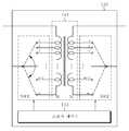
도 1은 본 발명의 바람직한 실시 예에 따른 무선 전력 전송 장치의 구성을 개략적으로 도시한 기능 블록도이다.
도 2는 도 1에 도시된 임피던스 정합기의 구성을 나타내는 상세 블럭도이다.
도 3은 도 1에 도시된 제1 공진형 안테나의 구성을 나타내는 상세 블럭도이다.
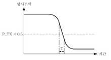
도 4는 본 발명의 바람직한 실시 예에서 무선 전력 수신부에 접속된 부하 장치의 존재 시 시간에 따른 반사 전력 곡선을 나타내는 도면이다.
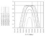
도 5는 본 발명의 바람직한 실시 예에서 무선 전력 수신부에 접속된 부하 장치의 존재 시 주파수에 따른 반사 전력 곡선을 나타내는 도면이다.
도 6은 본 발명의 바람직한 실시 예에서 무선 전력 수신부에 접속된 부하 장치의 존재 시 임피던스에 따른 반사 전력 곡선을 나타내는 도면이다.
도 7은 임피던스 조정을 수행하지 않은 종래 무선 전력 송수신부 간 거리에 따른 임피던스 변화를 나타내는 시뮬레이션 결과이다
도 8은 본 발명의 바람직한 실시 예에 따른 임피던스 정합기를 이용하여 임피던스 조정을 수행한 무선 전력 송수신부 간 거리에 따른 임피던스 변화를 나타내는 시뮬레이션 결과이다.
도 9는 임피던스 조정을 수행하지 않은 종래 무선 전력 송수신부 간 거리에 따른 전력 전송을 나타내는 시뮬레이션 결과이다.
도 10은 본 발명의 바람직한 실시 예에 따른 임피던스 정합기를 이용하여 임피던스 조정을 수행한 무선 전력 송수신부 간 거리에 따른 전력 전송을 나타내는 시뮬레이션 결과이다.
도 11은 본 발명의 바람직한 실시 예에 따른 무선 전력 송신부의 동작을 설명하는 흐름도이다.
도 12는 본 발명의 바람직한 실시 예에 따른 무선 전력 수신부의 동작을 설명하는 흐름도이다.1 is a functional block diagram schematically showing a configuration of a wireless power transmission apparatus according to an embodiment of the present invention.
FIG. 2 is a detailed block diagram illustrating a configuration of the impedance matcher shown in FIG. 1.
FIG. 3 is a detailed block diagram illustrating a configuration of the first resonant antenna shown in FIG. 1.
4 is a view showing a reflected power curve with time in the presence of a load device connected to a wireless power receiver in a preferred embodiment of the present invention.
5 is a diagram illustrating a reflected power curve according to frequency in the presence of a load device connected to a wireless power receiver in a preferred embodiment of the present invention.
6 is a diagram illustrating a reflected power curve according to impedance in the presence of a load device connected to a wireless power receiver in a preferred embodiment of the present invention.
7 is a simulation result showing the impedance change according to the distance between the conventional wireless power transceiver without performing the impedance adjustment.
FIG. 8 is a simulation result illustrating impedance change according to a distance between wireless power transceivers which perform impedance adjustment using an impedance matcher according to an exemplary embodiment of the present invention.
9 is a simulation result showing power transmission according to a distance between conventional wireless power transceivers without performing impedance adjustment.
FIG. 10 is a simulation result illustrating power transmission according to a distance between wireless power transceivers which perform impedance adjustment using an impedance matcher according to an exemplary embodiment of the present invention.
11 is a flowchart illustrating an operation of a wireless power transmitter according to an exemplary embodiment of the present invention.
12 is a flowchart illustrating an operation of a wireless power receiver according to an exemplary embodiment of the present invention.
이하, 첨부된 도면을 참조하여 본 발명의 바람직한 실시 예를 상세히 설명하기로 한다.Hereinafter, exemplary embodiments of the present invention will be described in detail with reference to the accompanying drawings.
도 1은 본 발명의 바람직한 실시 예에 따른 무선 전력 전송 장치의 구성을 개략적으로 도시한 기능 블록도이다.1 is a functional block diagram schematically showing a configuration of a wireless power transmission apparatus according to an embodiment of the present invention.
도 1을 참조하면, 본 발명의 바람직한 실시 예에 따른 무선 전력 전송 장치(1000)는 크게 무선 전력 송신부(100)와 무선 전력 수신부(200)로 구성된다.Referring to FIG. 1, a
상기 무선 전력 송신부(100)는 주파수 발진기(110), 전력 패스(pass) 스위치(120), 전력 증폭기(130), 임피던스 정합기(140), 방향성 전력 결합기(150), 제1 공진형 안테나(160), 출력 전력 검출기(170), 반사 전력 검출기(180) 및 송신 제어기(190)를 포함하여 구성된다.The
그리고, 상기 무선 전력 수신부(200)는 제2 공진형 안테나(210), 스위치(220), 정류기(230), 전력 신호 변환기(240), 충전 회로(250) 및 수신 제어기(260)를 포함하여 구성된다.The
상기 무선 전력 송신부(100)와 상기 무선 전력 수신부(100) 간의 무선 전력 전송은 자기공명 방식으로 이루어진다.Wireless power transmission between the
즉, 상기 무선 전력 송신부(100)로부터 자기공명 방식에 의해 전송된 무선 전력이 상기 무선 전력 수신부(200)에서 자기공명 방식에 의해 수신되고, 이렇게 수신된 무선 전력은 상기 무선 전력 수신부(200)에 접속된 부하(Load) 장치 (300)에 공급되거나 저장된다.That is, the wireless power transmitted by the magnetic resonance method from the
상기 무선 전력 송신부(100)와 상기 무선 전력 수신부(200) 간의 자기공명 방식에 의한 무선 전력 전송 과정을 개략적으로 살펴보면, 먼저, 상기 무선 전력 송신부(100)에서 무선 전력 신호를 생성하여 상기 무선 전력 신호가 가변 인덕터와 가변 캐패시터로 구성된 제1 공진형 안테나(160)에서 LC 공진에 의한 자기 에너지로 변환된다.Referring to the wireless power transmission process by the magnetic resonance method between the
그러면, 상기 변환된 자기 에너지가 상기 무선 전력 수신부(200)의 가변 인덕터와 가변 캐패시터로 구성된 제2 공진형 안테나(210)와 자기 결합(Magnetic coupling)함으로써 이루어진다.Then, the converted magnetic energy is achieved by magnetic coupling with the second
이때, 상기 제1 공진형 안테나(160)의 LC 공진 주파수와 상기 제2 공진형 안테나(210)의 LC 공진 주파수를 동일하게 맞춤으로써 동조를 일으켜 자기 에너지 결합을 극대화할 수 있다.At this time, the LC resonance frequency of the
즉, 상기 제1 및 제2 공진형 안테나(160, 210))의 공진 주파수 일치 정도에 따라 전송 효율은 급격히 증가하므로, 상기 제1 공진형 안테나(160)와 상기 제2 공진형 안테나(210) 사이의 공진 주파수를 일치시키기 위한 주파수 보정(Calibration)이 수행될 수 있다.That is, since the transmission efficiency is rapidly increased according to the degree of resonant frequency matching of the first and second
또한, 전송될 무선 전력의 세기를 키우거나 조절하기 위해서, 상기 무선 전력 송신부(100)에는 전력 증폭기(130)가 사용된다.In addition, a
이때, 상기 전력 증폭기(130)를 구동하기 위한 로드 임피던스는 수십 오옴[Ω]이 필요한 반면, 공진 특성(Q-factor)를 크게 하기 위한 상기 제1 공진형 안테나(160)의 실제 LC 코일의 임피던스는 수 오옴[Ω]에 지나지 않는다.In this case, the load impedance for driving the
이러한 상기 전력 증폭기(130)와 상기 제1 공진형 안테나 (160) 간의 임피던스 부정합에 의해서도 전송 효율은 크게 감소하므로 임피던스 정합에 대한 보정(Calibration) 또한 필수적이다.The transmission efficiency is also greatly reduced by the impedance mismatch between the
한편, 상기 자기 결합에 의한 자기력(Magnetic field)은, 전자기파(Electromagnetic wave)에 대한 맥스웰(Maxwell) 방정식의 제4 법칙에 따르면 "자기력은 항상 폐루프(Closed-Loop)를 이룬다" 라고 정의하고 있다.On the other hand, the magnetic field due to magnetic coupling is defined as "the magnetic force is always closed-loop" according to the fourth law of Maxwell's equation for electromagnetic waves. .
따라서, 물결파와 같이 멀리 퍼져나가는 성질의 전기력(Electric field)과 달리, 자기력은 원을 그리며 되돌아 오는 성질로 인해 매질에 의한 손실이 없다면 항상 에너지는 보존된다고 해석할 수 있다.Therefore, unlike the electric field of the nature of spreading far, such as water waves (magnetic field), it can be interpreted that the energy is always conserved if there is no loss by the medium due to the magnetic force is returned in a circle.
이러한 성질을 활용하면 상기 무선 전력 송신부(100)와 상기 무선 전력 수신부(200) 사이에 통신이 이루어 지지 않은 환경(이를 테면, 무선통신을 위한 트랜스시버(transceiver)를 구비하지 않은 환경) 하에서, 상기 무선 전력 송신부(100)가 상기 무선 전력 수신부(200)의 환경을 인지하도록 할 수 있다.By utilizing this property, the
즉, 상기 무선 전력 송신부(100)가 켜져 있을 때 무선 전력 수신부(200)에 접속된 부하 장치(300)가 없거나 켜져 있지 않다면(즉, 상기 무선 전력 수신부(200)에 접속되어 있지 않다면), 상기 무선 전력 송신부(100)에서 볼 때 에너지 손실이 없으므로 무선 전력 전송 환경 내에 상기 무선 전력 수신부(200)에 접속된 부하 장치(300)가 존재하지 않는 것으로 판단할 수 있다.That is, if there is no
반대로, 만약 상기 무선 전력 수신부(200)에 접속된 부하 장치(300)가 존재한다면, 상기 무선 전력 송신부(100)에서 볼 때 에너지 손실이 발생하므로 상기 무선 전력 수신부(200)에 접속된 부하 장치(300)가 존재한다고 판단할 수 있다.On the contrary, if there is a
따라서, 상기 무선 전력 송신부(100)로부터 송신된 무선 전력이 반사되는 반사 전력을 측정하여 상기 무선 전력 수신부(200)에 접속된 부하 장치(300)의 존재 유무를 판별하고, 상기 무선 전력 수신부(200)에 접속된 부하 장치(300)의 존재 시 공진 주파수 조절 및 임피던스 조절을 통해 최적의 상태로 무선 전력을 전송하여 무선 전력 전송 효율을 향상시킬 수 있다.Therefore, by measuring the reflected power reflected by the wireless power transmitted from the
여기서, 상기 부하 장치(300)는 상기 무선 전력 송신부(100)로부터 상기 무선 전력 수신부(200)로 전달된 무선 전력을 수신하여 상기 부하 장치(300)에 전력을 충전하거나 가정용 전원을 공급하도록 하여 공급된 전력을 소모하는 장치이다.Here, the
예를 들면, 상기 부하 장치는 텔레비전 및 컴퓨터와 같은 전자/가전 기기들 또는 배터리일 수 있다.For example, the load device may be a battery or an electronic / home appliance such as a television and a computer.
이제, 본 발명의 일 실시 예에 따른 무선 전력 전송 장치(1000)의 무선 전력 송신부(100)와 부하 장치(300)가 연결될 수 있는 무선 전력 수신부(200)의 각 구성과 동작 방법을 보다 자세하게 기술하기로 한다.Now, each configuration and operation method of the
먼저, 본 발명의 일 실시 예에 무선 전력 송신부(100)의 구성 및 동작 방법을 살펴보기로 한다.First, the configuration and operation method of the
상기 주파수 발진기(110)는 외부전력을 무선 전력 신호로 변환한다. 이때, 무선 전력 신호는 교류신호로써, 외부에서 입력되는 교류신호가 무선 전력 전송에 적절하지 않은 교류신호의 형태를 가질 수 있으므로 상기 주파수 발진기(110)는 외부전력을 무선으로 송신하기에 적절한 교류신호로 변환하여 출력한다.The
상기 주파수 발진기(110)에서 생성된 무선 전력 신호의 발진 주파수는 제1 공진형 안테나(160)의 가변 인덕터와 가변 캐패시터 값에 의해 설정된 공진 주파수보다 작으며, 상기 제1 공진형 안테나(160)에서 수신측까지 바라본 상호 인덕턴스 값이 더해져서 계산된 공진 주파수와 같다.The oscillation frequency of the wireless power signal generated by the
상기 전력 증폭기(130)는 무선 전력 송신의 효율을 높이기 위해 상기 무선 전력 신호의 세기를 크게 하거나 소정의 세기로 조절되도록 증폭하여 출력한다.The
이때, 상기 주파수 발진기(110)와 상기 전력 증폭기(130) 사이에는 전력 패스 스위치(120)가 구비될 수 있다.In this case, a
이러한 상기 전력 패스 스위치(120)는 상기 수신부(200) 자체나 상기 수신부(200)에 접속된 부하 장치(300)의 존재 유무를 판별하기 위하여 주기적으로 무선 전력을 송신해야 할 필요가 있는데, 이때 전력의 낭비를 최소화하기 위하여 상기 주파수 발생기(110)와 상기 임피던스 정합기(140)(또는 상기 방향성 전력 결합기(150))가 연결되도록 상기 전력 증폭기(130)를 바이패스(Bypass)하는 경로를 제공한다.The power path switch 120 needs to periodically transmit wireless power in order to determine whether the
즉, 상기 수신부(200) 또는 상기 수신부(200)에 접속된 부하 장치(300)의 존재 유무를 판별하는 경우, 상기 전력 패스 스위치(120)를 통해 상기 주파수 발생기(110)로부터 생성된 무선 전력 신호를 증폭하지 않고 바이패스 시킴으로써 주기적으로 이루어지는 수신측 존재 유무 판별을 수행할 수 있고 불필요한 전력 낭비를 최소화할 수 있다.That is, when it is determined whether the
상기 임피던스 정합기(140)는 상기 전력 증폭기(120)와 상기 제1 공진형 안테나(160) 사이에 위치며, 상술한 바와 같이 최적의 전송 효율로 상기 무선 전력 신호를 전송하기 위해, 상기 전력 증폭기(130)의 로드 임피던스와 상기 제1 공진형 안테나(160)의 LC 코일의 간 임피던스 정합을 제공한다.The
이러한 상기 임피던스 정합기(140)는 트랜스포머(transformer)로 구현되며, 상기 트랜스포머의 권선비를 조절함으로써 임피던스 정합을 수행할 수 있다.The
특히, 상기 트랜스포머의 권선비를 이용한 임피던스 정합은 임피던스의 실수부(Real) 성분을 정합할 수 있게 된다.In particular, impedance matching using the turns ratio of the transformer can match the real component of the impedance.
구체적으로, 상기 전력 증폭기(130) 측에서 주파수 발생기(110) 쪽으로 바라본 임피던스를 Z1, Z1에 연결된 1차측 코일의권선수를 N1이라 하고, 상기 제1 공진형 안테나(160) 측에서 수신부 측으로 바라본 임피던스를 Z2, Z2에 연결된 2차측 코일의 권선수를 N2라 가정하면, 상기 1차측 코일과 상기 2차측 코일로 구성된 트랜스포머의 권선비(n)는 식(1)과 같을 때 상기 임피던스 Z1과 Z2가 정합된다:Specifically, the impedance viewed toward the

그러나, 상기 제1 공진형 안테나(160) 측에서 수신부 측으로 바라본 임피던스(Z2)는 수신측에 접속된 부하 장치(300)에 따라 변동될 수 있으므로, 상기 전력 증폭기(130)와 상기 제1 공진형 안테나(160) 간의 임피던스 정합을 위해서는 상기 권선비(n)가 가변될 수 있어야 한다.However, since the impedance Z2 viewed from the side of the first
따라서, 상기 임피던스 정합기(140)에 사용된 트랜스포머는 가변 트랜스포머로 구현될 수 있으며, 그 일례가 도 2에 도시된다.Thus, the transformer used in the
도 2는 도 1에 도시된 임피던스 정합기의 구성을 나타내는 상세 블럭도이다.FIG. 2 is a detailed block diagram illustrating a configuration of the impedance matcher shown in FIG. 1.
도 2를 참조하면, 상기 임피턴스 정합기(140)는 1차측 권선(N1)과 2차측 권선(N2)으로 구성된 변압 모듈(141), 상기 1차측 권선(N1)에 설치된 다수의 제1 스위치(SW1), 및 상기 2차측 권선(N2)에 설치된 다수의 제2 스위치(SW2), 및 상기 다수의 제1 및 제2 스위치(SW1, SW2)에 연결되며, 임피던스의 실수부 성분을 조절하기 위해 상기 1차측 권선(N1)과 상기 2차측 권선(N2)의 권선비(n)가 가변되도록 상기 제1 및 제2 스위치들(SW1, SW2)을 턴-온 또는 턴-오프시킴으로써 제어하는 스위치 제어기(143)를 포함한다.2, the
상기 방향성 전력 결합기(150)는 상기 전력 증폭기(130)와 상기 임피던스 정합기(140) 사이 또는 상기 임피던스 정합기(140)와 상기 제1 공진형 안테나(160) 사이에 설치될 수 있다.The
이러한 상기 방향성 전력 결합기(150)는 다수의 단자로 구성되며, 한 단자로 입력된 신호가 나머지 단자 중 하나로만 출력되고 다른 나머지 단자로는 출력되지 않도록 함으로써 입력되는 신호의 방향을 변환한다. 이때, 상기 입력되는 신호의 방향은 일정한 방향성을 갖게 된다.The
이러한 방향성 전력 결합기(150)는 그를 통해 입력된 상기 무선 전력 신호를 상기 제1 공진형 안테나(160)로 출력하여 전달하고, 상기 제1 공진형 안테나(160)를 통해 폐루프를 형성하는 자기 결합 에너지로부터 반사되는 무선 전력 신호(이하 '반사 무선 전력 신호'라 칭함)를 입력 받아 출력한다.The
예를 들어, 상기 방향성 전력 결합기(150)는 상기 전력 증폭기(130) 또는 상기 임피던스 정합기(140)에서 제1 포트를 통해 입력되는 상기 무선 전력 신호를 제2 포트를 통해 상기 제1 공진형 안테나(160)로 출력하고, 상기 제2 포트를 통해 상기 제1 공진형 안테나(160)로부터 입력된 상기 반사 무선 전력 신호를 제3 포트를 통해 출력되도록 방향성을 갖는다.For example, the
이처럼, 상기 방향성 전력 결합기(150)는 다수개의 단자를 갖는 써큘레이터(circulator)로 구성되는 것이 바람직하다.As such, the
이러한 써큘레이터는 다수개의 단자를 포함하나, 어느 단자로 입력된 신호든지 한 방향으로만 전달한다.The circulator includes a plurality of terminals, but transmits a signal input to either terminal only in one direction.
이때, 상기 방향성 전력 결합기(150)에는 효율적인 무선 전력 전송을 위해 출력 전력에 대한 반사 전력의 비율을 계산하기 위한 전력 검출기가 연결된다.At this time, the
이러한 검출기는 출력 전력 검출기(170) 및 반사 전력 검출기(180)가 사용된다.Such a detector is used with an
상기 출력 전력 검출기(170)는 상기 방향성 전력 결합기(150)를 통해 제1 공진형 안테나(160)로 전달되어 수신측으로 출력된(예컨대, 상기 방향성 전력 결합기(150)의 제1 포트로부터 입력 받아 제2 포트로 출력된) 상기 무선 전력 신호의 출력 전력(Pout=Pdetect)을 측정한다.The
그리고, 상기 반사 전력 검출기(180)는 상기 제1 공진형 안테나(160)로부터 상기 방향성 전력 결합기(150)를 통해 입력 받아 출력된(예컨대, 상기 방향성 전력 결합기(150)의 제2 포트로부터 입력 받아 제3 포트로 출력된) 상기 반사 무선 전력 신호의 반사 전력(Preflect)을 검출한다.In addition, the reflected
이렇게 검출된 상기 출력 전력(Pout=Pdetect) 대 상기 반사 전력(Preflect)의 비율에 따라 상기 수신부(200)에 접속된 부하 장치(300)의 존재 유무를 파악한다.The presence or absence of the
상기 제1 공진형 안테나(160)는 가변 인덕터와 가변 캐패시터를 포함하여 구성되며, 상기 무선 전력 신호가 입력되면 인덕턴스와 캐패시턴스의 가변에 의한 LC 공진에 의해 자기 에너지로 변환되어 폐루프를 형성한다.The first
상기 제1 공진형 안테나(160)는 수신측과의 LC 공진에 의한 공진 주파수를 조절할 뿐만 아니라 상기 LC 가변에 의한 임피던스 정합을 수행한다.The first
이때, 상술한 상기 임피던스 정합기(140)가 임피던스의 실수부 성분을 조절하는 정합인 반면, 상기 제1 공진형 안테나(160)는 임피던스의 허부수(Imaginary) 성분을 조절하는 정합을 수행한다.In this case, the
상기 임피던스의 허수부 성분은 상기 제1 공진형 안테나(160)의 가변 인덕터와 가변 캐패시터를 가변하여 인덕턴스와 캐패시턴스에 변화를 줌으로써 조절된다.The imaginary component of the impedance is adjusted by varying inductance and capacitance by varying the variable inductor and the variable capacitor of the first
도 3은 도 1에 도시된 제1 공진형 안테나의 구성을 나타내는 상세 블럭도이다.FIG. 3 is a detailed block diagram illustrating a configuration of the first resonant antenna shown in FIG. 1.
도 3을 참조하면, 상기 제1 공진형 안테나(160)는 가변 캐패시터 회로(161)와 가변 인덕터 회로(163)가 직렬로 연결되어 있는 것으로 도시되었으나, 이에 한정되는 것은 아니며 상기 가변 캐패시터 회로(161)와 상기 가변 인덕터 회로(163)가 병렬로 연결되거나 또는 다른 구성의 다양한 LC 가변 회로로 구성될 수도 있다.Referring to FIG. 3, the first
상기 가변 캐패시터 회로(161)는 다수의 캐패시터(C1, C2, C3, ..., Cn)가 병렬로 연결되고, 상기 다수의 캐패시터(C1, C2, C3, ..., Cn) 각각에는 다수의 제3 스위치(SW3)가 직렬로 연결된다.The
상기 가변 인덕터 회로(163)는 다수의 인덕터(L1, L2, L3, ..., Ln)가 직렬로 연결되고, 상기 다수의 인덕터(L1, L2, L3, ..., Ln) 각각에는 다수의 제4 스위치(SW4)가 병렬로 연결된다.The
그리고, 상기 스위치 제어기(165)는 상기 제3 및 제4 스위치들(SW3, SW4)에 연결되며, 수신측과의 공진 주파수 및 최적 임피던스에 대응되는 인덕턴스와 캐패시턴스를 탐색하기 위해 상기 다수의 인덕터와 상기 다수의 캐패시터가 가변되도록 상기 다수의 제3 및 제4 스위치들(SW3, SW4)을 턴-온 또는 턴-오프 시킴으로써 제어한다.The
이때, 상기 임피던스의 허부수 성분 중 음의 허수부 성분은 상기 가변 캐패시터 회로(161)에 의한 캐패시턴스의 가변에 의해 조절되며, 양의 허수부 성분은 상기 가변 인덕터 회로(163)에 의한 인덕턴스의 가변에 의해 조절될 수 있다.At this time, the negative imaginary component of the imaginary component of the impedance is adjusted by the variable capacitance of the
상기 송신 제어기(190)는 상기 무선 전력 송신부(100)를 전반적으로 제어한다.The
보다 구체적으로, 상기 송신 제어기(190)는 초기 공진 주파수를 설정하고 설정된 초기 공진 주파수를 이용하여 상기 제1 공진형 안테나(160)를 통해 전송될 무선 전력 신호를 생성하여 증폭하며, 상기 증폭된 무선 전력 신호를 상기 제1 공진형 안테나(160)의 인덕터(L)와 캐패시터(C)의 LC 공진에 의해 폐루프를 형성하는 자기 에너지로 변환한 후, 부하 장치(300)가 접속된 무선 전력 수신부(200)와의 자기 결합을 통한 자기 결합 에너지로부터 반사 무선 전력 신호를 상기 제1 공진형 안테나(160)를 통하여 수신하여 검출하도록 제어한다.More specifically, the
이때, 상기 송신 제어기(190)는 상기 출력 전력 검출기(170)와 상기 반사 전력 검출기(180)로부터 검출된 상기 무선 전력 신호의 출력 전력(Pout=Pdetect)과 상기 반사 무선 전력 신호의 반사 전력(Preflect)을 입력받아 상기 출력 전력(Pout=Pdetect)에 대한 상기 반사 전력의 변화 정도에 따라 상기 무선 전력 수신부(200)에 접속된 부하 장치(300)의 존재 유무를 파악한다.At this time, the
상기 부하 장치(300)가 존재하는 것으로 파악된 경우, 상기 송신 제어기(190)는 상기 부하 장치(300)로 전송될 무선 전송 전력의 세기에 해당하는 전력 세기를 갖도록 상기 주파수 발생기(110)로부터 생성된 무선 전력 신호의 전력을 증폭시키며, 전력이 증폭된 상태에서의 무선 전력 신호가 상기 제1 공진형 안테나(160)를 통해 수신부(200)로 전송되도록 제어한다.If it is determined that the
이때, 상기 송신 제어기(190)는 최대 전력 전송이 일어나도록 상기 임피던스 정합기(140) 및 상기 제1 공진형 안테나(160)를 제어하여 공진 주파수 조정 및 임피던스 정합을 수행한다.At this time, the
즉, 상기 송신기 제어기(190)는 상기 임피던스 정합기(140)의 임피던스의 실수부 성분을 변화시키면서 상기 반사 전력 검출기(180)에서 수신된 반사 무선 전력 신호의 최소 변곡점을 탐색하여 탐색된 최소 변곡점에 해당하는 임피던스의 실수부 성분을 상기 임피던스 정합기의 최적 임피던스의 실수부 성분으로 설정한다.That is, the
또한, 상기 송신 제어기(190)는 상기 제1 공진형 안테나(160)의 주파수와 임피던스의 허수부 성분을 각각 변화시키면서 상기 반사 전력 검출기(180)에서 수신된 각각의 반사 무선 전력 신호의 최소 변곡점을 탐색하여 탐색된 각각의 최소변곡점에 해당하는 주파수와 임피던스의 허수부 성분을 상기 제1 공진형 안테나(160)의 공진 주파수와 최적 임피던스의 허수부 성분으로 설정한다.In addition, the
이하에서, 상기 송신 제어기(190)가 상기 무선 전력 수신부(200)에 접속된 부하 장치(300)를 파악하고, 상기 부하 장치(300) 존재 시, 최적의 상태로 무선 전력을 전송하기 위한 공진 주파수 설정 및 최적 임피던스 설정에 과정을 상세히 설명하기로 한다.Hereinafter, the
도 4는 본 발명의 바람직한 실시 예에서 무선 전력 수신부에 접속된 부하 장치의 존재 시 시간에 따른 반사 전력 곡선을 나타내는 도면이고, 도 5는 본 발명의 바람직한 실시 예에서 무선 전력 수신부에 접속된 부하 장치의 존재 시 주파수에 따른 반사 전력 곡선을 나타내는 도면이며, 도 6은 본 발명의 바람직한 실시 예에서 무선 전력 수신부에 접속된 부하 장치의 존재 시 임피던스에 따른 반사 전력 곡선을 나타내는 도면이다.4 is a view showing a reflected power curve with time in the presence of a load device connected to a wireless power receiver in a preferred embodiment of the present invention, Figure 5 is a load device connected to a wireless power receiver in a preferred embodiment of the present invention 6 is a diagram illustrating a reflected power curve according to frequency in the presence of, FIG. 6 is a diagram showing a reflected power curve according to impedance in the presence of a load device connected to a wireless power receiver in a preferred embodiment of the present invention.
도 4를 참조하면, 상기 반사 전력은 일정하게 유지되다가 시간이 점점 흐름에 따라 급격히 감소되는 구간(T)이 발생된다.Referring to FIG. 4, a section T is generated in which the reflected power is kept constant and then rapidly decreases with time.
상기 송신 제어기(190)는 상기 구간(T), 즉 반사 전력이 급격히 감소하는 구간(T)에서 상기 무선 전력 수신부(200)에 부하 장치(300)가 연결되거나 상기 무선 전력 수신부(200)에 접속된 부하 장치(300)의 전원이 턴-온 된 것으로 판단할 수 있다.The
상기 반사 전력이 급격히 감소하는 구간(T)의 기준은, 예를 들어, 상기 무선 전력 송신부(100)의 미리 설정된 설정값 1에 따라 상기 출력 전력(Pout=Pdetect)에 대한 상기 반사 전력(Preflect)의 비율(이하 '출력 대 반사 전력비'로 칭함)이 상기 설정값 1과 같거나 크면 상기 무선 전력 수신부(200)에 접속된 부하 장치(300)가 없는 것으로 판단한다.The reference of the period T in which the reflected power decreases rapidly may include, for example, the reflected power (Pout = Pdetect ) with respect to the output power Pout = Pdetect according to a
예를 들어, 상기 출력 전력(Pout=Pdetect) = 1, 상기 설정값 1 = 0.8로 가정하였을 때, 상기 출력 대 반사 전력비≥0.8이면, 상기 무선 전력 수신부(200)에 접속된 부하 장치(300)에 의한 전력 손실이 아닌 공중에서 손실된 오차 범위 내의 반사 손실로 보고 상기 무선 전력 수신부(200)에 접속된 부하 장치(300)가 없는 것으로 판단한다.For example, assuming that the output power (Pout = Pdetect ) = 1 and the
반대로, 상기 반사 전력비< 0.8이면, 이는 상기 무선 전력 수신부(200)에 접속된 부하 장치(300)에 의한 전력 손실로 보고 상기 무선 전력 수신부(200)에 접속된 부하 장치(300)가 있는 것으로 판단한다.On the contrary, if the reflected power ratio <0.8, this is regarded as a power loss by the
이와 같이, 상기 무선 전력 수신부(200)에 접속된 부하 장치(300)가 존재하는 것으로 판단되면, 최적의 상태로 무선 전력을 전송하기 위해 공진 주파수 설정 및 임피던스 정합이 다음과 같이 수행된다:As such, when it is determined that the
먼저, 상기 송신 제어기(190)는 상기 제1 공진형 안테나(160)의 인덕턴스와 캐패시턴스의 가변을 통한 주파수 조절(주파수 튜닝)에 따른 상기 반사 무선 전력 신호로부터 반사 전력(Preflect)을 검출하도록 제어한다.First, the
이러한 과정을 거치면, 도 5에 도시된 바와 같은 주파수에 따른 반사 전력 곡선을 얻을 수 있다.Through this process, the reflection power curve according to the frequency as shown in FIG. 5 can be obtained.
도 5에 도시된 것처럼, 반사 전력 곡선에 최소 변곡점(P)이 존재하는 것을 알 수 있으며, 상기 최소 변곡점(P)에 해당하는 주파수에서 반사 전력(Preflect)이 최저임을 알 수 있다.As shown in FIG. 5, it can be seen that the minimum inflection point P exists in the reflection power curve, and the reflection power Preflect is the lowest at the frequency corresponding to the minimum inflection point P.
이는 상기 최소 변곡점(P)에 해당하는 주파수에서 공진이 일어났음을 의미하며, 따라서 상기 최소 변곡점(P)에 해당하는 주파수가 공진 주파수가 된다.This means that resonance occurs at the frequency corresponding to the minimum inflection point P, and thus the frequency corresponding to the minimum inflection point P becomes the resonance frequency.
이처럼, 상기 송신 제어기(190)는 상기 공진 주파수를 설정하기 위해 상기 제1 공진형 안테나(160)의 인덕턴스와 캐패시턴스의 가변을 통해 주파수를 조절하게 된다.As such, the
한편, 상기 송신 제어기(190)는 또한 상기 임피던스 정합기(140) 및 제1 공진형 안테나(160)의 임피던스 가변을 통한 임피던스 조절(임피던스 튜닝)에 따른 상기 반사 무선 전력 신호로부터 상기 반사 전력(Preflect)을 검출하도록 제어한다.On the other hand, the
이러한 과정을 거치면, 도 6에 도시된 바와 같은 임피던스에 따른 반사 전력 곡선을 얻을 수 있다.Through this process, the reflection power curve according to the impedance as shown in FIG. 6 can be obtained.
도 6에 도시된 것처럼, 반사 전력 곡선에 최소 변곡점(P)이 존재하는 것을 알 수 있으며, 상기 최소 변곡점(P)에 해당하는 임피던스에서 반사 전력(Preflect)이 최저임을 알 수 있다.As shown in FIG. 6, it can be seen that the minimum inflection point P exists in the reflection power curve, and the reflection power Preflect is the lowest at the impedance corresponding to the minimum inflection point P.
이는 상기 최소 변곡점(P)에 해당하는 임피던스에서 LC 공진이 일어났음을 의미하며, 따라서 상기 최소 변곡점(P)에 해당하는 임피던스가 정합된 최적 임피던스가 된다.This means that LC resonance has occurred at the impedance corresponding to the minimum inflection point P, and thus the impedance corresponding to the minimum inflection point P is a matched optimum impedance.
상기 송신 제어기(190)는 상기 최적 임피던스를 설정하기 위해 상기 임피던스 정합기(140)를 통해 상기 최적 임피던스의 실수부 성분을 조절하고, 상기 제1 공진형 안테나(160)를 통해 상기 최적 임피던스의 허수부 성분을 조절하게 된다.The
이때, 최적 임피던스의 실수부 성분 및 허수부 성분의 탐색 및 설정은 도 6에 설명한 과정과 동일하게 수행된다.At this time, the search and setting of the real part component and the imaginary part component of the optimum impedance are performed in the same manner as described in FIG.
도 7 내지 10에서는 본 발명의 바람직한 실시 예에 따른 임피던스 정합기(140)의 사용 유무에 따른 임피던스 변화 및 전송 전력 변화를 살펴보기로 한다.7 to 10, the impedance change and the transmission power change according to the use of the
도 7은 임피던스 조정을 수행하지 않은 종래 무선 전력 송수신부 간 거리에 따른 임피던스 변화를 나타내는 시뮬레이션 결과이고, 도 8은 본 발명의 바람직한 실시 예에 따른 임피던스 정합기를 이용하여 임피던스 조정을 수행한 무선 전력 송수신부 간 거리에 따른 임피던스 변화를 나타내는 시뮬레이션 결과이다.FIG. 7 is a simulation result showing an impedance change according to a distance between conventional wireless power transceivers without performing impedance adjustment, and FIG. 8 is a wireless power transmission / reception performed by performing impedance adjustment using an impedance matcher according to a preferred embodiment of the present invention. Simulation results showing impedance change according to the distance between parts.
또한, 도 9는 임피던스 조정을 수행하지 않은 종래 무선 전력 송수신부 간 거리에 따른 전력 전송을 나타내는 시뮬레이션 결과이고, 도 10은 본 발명의 바람직한 실시 예에 따른 임피던스 정합기를 이용하여 임피던스 조정을 수행한 무선 전력 송수신부 간 거리에 따른 전력 전송을 나타내는 시뮬레이션 결과이다.9 is a simulation result showing power transmission according to a distance between conventional wireless power transceivers which do not perform impedance adjustment, and FIG. 10 is a radio in which impedance adjustment is performed using an impedance matcher according to a preferred embodiment of the present invention. Simulation results showing power transmission according to the distance between power transmission and reception units.
도 7과 8을 참조하면, 약 13.56MHz의 주파수를 이용한 무선 전력 전송에 있어 무선 전력 송수신부(100, 200) 간 거리에 따른 임피던스 변화를 비교할 수 있다.7 and 8, in the wireless power transmission using a frequency of about 13.56 MHz, the impedance change according to the distance between the
도 7에 도시된 바와 같이, 임피던스 조정을 수행하지 않은 경우, 50[Ω]에 근사한 m3을 기준으로 볼 때, 상기 무선 전력 송수신부(100, 200) 간 거리가 멀수록 상기 m3로부터 멀어지는 것을 알 수 있다.As shown in FIG. 7, when the impedance adjustment is not performed, the distance between the wireless power transmitters and
이는 상기 무선 전력 송수신부(100, 200) 간 거리가 멀수록 커플링(coupling) 계수가 작아지므로 50[Ω]을 기준으로 임피던스가 작아지는 방향으로 변한 것이다.Since the coupling coefficient becomes smaller as the distance between the wireless power transmitters and
그러나, 본 발명의 바람직한 실시 예에 따른 임피던스 정합기(140)를 사용하여 임피던스 조정을 수행한 경우, 도 7에 비해 50[Ω]에 근사한 m27로 집중되는 것을 알 수 있다.However, when impedance adjustment is performed using the
이는 상기 임피던스 정합기(140)의 가변 트랜스포머의 권선비를 가변하여 임피던스의 실수부 성분을 조절함으로써 향상된 임피던스 정합이 이루어지도록 한 것이다.This is to improve the impedance matching by varying the winding ratio of the variable transformer of the
이와 같이, 본 발명의 바람직한 실시 예에 따른 임피던스 정합기(140)를 사용하여 임피던스의 실수부 성분을 50[Ω]에 근사하도록 조절하여 정합할 수 있다.In this way, the
마찬가지 방법으로, 본 발명의 바람직한 실시 예에 따른 제1 공진형 안테나(160)를 사용하여 임피던스의 허수부 성분을 조절하여 좀 더 세밀하고 정확한 임피던스 정합이 수행될 수 있다.In a similar manner, more precise and accurate impedance matching can be performed by adjusting the imaginary component of impedance using the first
도 9과 10을 참조하면, 상기 임피던스 정합기(140)의 가변 트랜스포머의 권선비를 조절하여 임피던스의 실수부를 조절하였을 때 전송 전력 변화를 비교할 수 있다.9 and 10, when the real part of the impedance is adjusted by adjusting the winding ratio of the variable transformer of the
도 9에 도시된 바와 같이, 임피던스 조정을 수행하지 않은 경우, 주파수에 따라 전송 전력의 크기가 다른 것을 알 수 있다.As shown in FIG. 9, when the impedance adjustment is not performed, it can be seen that the magnitude of the transmission power varies depending on the frequency.
이는 자기공명 방식을 이용한 무선 전력 전송에 있어, 상기 무선 전력 송신부(100)와 상기 무선 전력 수신부(200)의 공진 주파수가 동일하게 설정되었을 때 반사되는 전력을 최소화하고 전송되는 전력을 극대화할 수 있는데, 상기 무선 전력 송신부(100)와 상기 무선 전력 수신부(200)의 거리가 가까워지거나 멀어짐에 따라 상기 무선 전력 송수신부(100, 200) 간 공진 주파수의 재조정(detuing)이 발생하여 전력 전송이 효율적으로 일어나지 않았음을 의미한다.In the wireless power transmission using the magnetic resonance method, when the resonant frequencies of the
그러나, 본 발명의 바람직한 실시 예에 따른 임피던스 정합기(140)를 사용하여 임피던스 조정을 수행한 경우, 도 10에 도시된 바와 같이 전력 전송 크기가 거의 동일하게 된다.However, when impedance adjustment is performed using the
이때, 상기 임피던스 조정과 함께, 본 발명의 바람직한 실시 예에 따른 제1 공진형 안테나(160)를 이용하여, 도 5에 설명한 바와 같은 주파수 조정을 통해 상기 무선 전력 송신부(100)와 상기 무선 전력 수신부(200) 간의 공진 주파수를 재조정하는 과정이 다시 수행될 수도 있다.In this case, together with the impedance adjustment, the
이제, 본 발명의 일 실시 예에 무선 전력 수신부(200)의 구성 및 동작 방법을 살펴보기로 한다.Now, a configuration and operation method of the
다시 도 1을 참조하면, 상기 제2 공진형 안테나(210)는 인덕터(또는 가변 인덕터)와 가변 캐피시터(또는 가변 캐패시터)로 구성되며, 인덕턴스와 캐패시턴스에 의한(또는 인덕턴스와 캐패시턴스의 가변을 통한) LC 공진에 의해 폐루프를 형성하는 자기 에너지로 변환되어 상기 무선 전력 송신부(100)로부터 형성된 자기 에너지와 자기 결합한다.Referring back to FIG. 1, the second
이렇게 형성된 자기 결합 에너지는 역시 폐루프를 형성하고 있으므로, 상기 자기 결합 에너지로부터 변환된 무선 전력 신호를 자기공명 방식에 의해 수신한다.The magnetic coupling energy thus formed also forms a closed loop, and thus receives the wireless power signal converted from the magnetic coupling energy by magnetic resonance.
그런 다음, 상기 제2 공진형 안테나(210)는 상기 무선 전력 수신부(200)에 접속된 부하 장치(300)에 상기 무선 전력 송신부(100)로부터 수신된 무선 전력 신호를 공급하고, 잔여 무선 전력 신호를 상기 무선 전력 송신부(200)로 반사한다.Then, the second
이러한 제2 공진형 안테나(210)는 도 3에 도시된 바와 같이, 상기에 상술한 제1 공진형 안테나(160)와 동일한 구성을 가지므로, 이에 대한 상세 설명은 상술한 것으로 대체하기로 한다.Since the second
상기 스위치(220)는 상기 제2 공진형 안테나(210)와 정류기(230) 사이에 위치하며, 상기 제2 공진형 안테나(210)가 상기 무선 전력 송신부(100)와의 자기 결합을 수행하거나 차단하도록 스위칭한다.The
다시 말해, 상기 스위치(220)는 무선 전력 수신부(200)의 수신대기상태 또는 수신종결상태를 결정한다.In other words, the
상기 스위치(220)가 온(ON)되면 상기 무선 전력 수신부(200)는 무선 전력 신호를 수신하게 되고, 상기 스위치(220)가 오프(OFF)되면 상기 무선 전력 수신부(200)는 무선 전력 신호의 수신을 중단하게 된다.When the
예를 들어, 상기 스위치(220)는 상기 무선 전력 수신부(200)에 접속된 부하 장치(300)에서 더 이상 전력이 필요하지 않을 때(예컨대, 배터리의 충전이 완료되었거나 텔레비전이나 컴퓨터 등의 전자/가전기기 등이 오프되었을 때) 상기 무선 전력 송신부(100)와의 자기 결합을 종료하거나, 반대로 상기 무선 전력 수신부(200)에 접속된 부하 장치(300)에서 전력이 필요할 때(예컨대, 배터리의 충전을 시작하거나 텔레비전이나 컴퓨터 등의 전자/가전기기 등이 온 되었을 때) 상기 무선 전력 송신부(100)와의 자기 결합을 시작하도록 스위칭한다.For example, when the
상기 정류기(230)는 상기 제2 공진형 안테나(210)로부터 수신된 무선 전력 신호를 정류한다.The
상기 전력 신호 변환기(240)는 상기 부하 장치(300)가 접속되며, 상기 부하 장치(300)의 전원부(미도시)에 전력을 충전하거나 가정용 전원을 공급하도록 상기 정류기(230)로부터 정류된 무선 전력 신호를 적절한 직류 신호 또는 교류 신호의 형태로 변환한다.The
예를 들어, 상기 전력 신호 변환기(240)에 접속된 상기 부하 장치(300)의 전원부가 배터리 충전기와 같이 일정 시간 동안 충전하여 일정한 용량을 저장하는 방식일 경우, 상기 전력 신호 변환기(240)는 상기 부하 장치(300)의 전원부에 전력을 충전하기 위해 상기 수신된 무선 전력 신호를 적절한 직류 신호로 변환한다.For example, when the power unit of the
이 경우, 상기 부하 장치(300)가 접속된 무선 전력 수신부(200)는 상기 배터리 충전기의 용량을 검출할 수 있는 배터리 용량 검출기(미도시)를 더 포함할 수 있으며, 상기 배터리 용량 검출기(미도시)로부터 검출된 신호를 상기 무선 전력 수신부(200)의 수신 제어기(260)로 전달한다.In this case, the
또한, 상기 부하 장치(300)의 전원부가 전자/가전기기와 같이 계속적으로 전원을 공급해야 하는 방식일 경우, 상기 전력 신호 변환기(240)는 상기 부하 장치(300)의 전원부에 가정용 전원을 공급하기 위해 상기 수신된 무선 전력 신호를 적절한 교류 신호로 변환한다.In addition, when the power supply unit of the
따라서, 상기 전력 신호 변환기(240)는 상기 수신된 무선 전력 신호를 적절한 교류 신호 형태로 변환하기 위한 교류 변환기(AC-AC Converter)(미도시)와 상기 수신된 무선 전력 신호를 적절한 직류 신호 형태로 변환하기 위한 교류-직류 변환기(AC-DC Converter)(미도시) 등을 포함할 수 있다.Accordingly, the
상기 충전 회로(250)는 상기 전력 신호 변환기(240)로부터 변환된 전력을 충전하는 회로이다. 이러한 충전 회로(250)는 도 1에 도시된 바와 같이 무선 전력 수신부(200)에 포함될 수도 있으나, 이에 한정되는 것은 아니며 상기 부하 장치(300)에 포함될 수도 있다.The charging
상기 수신 제어기(260)는 상기 무선 전력 수신부(200)를 전반적으로 제어한다.The
구체적으로, 상기 수신 제어기(260)는 상기 제2 공진형 안테나(210)에서 자기 공명 방식에 의해 무선 전력 신호를 수신하여 상기 부하 장치(300)에 전력이 공급되도록 제어하고, 상기 잔여 무선 전력 신호를 상기 무선 전력 송신부(100)로 반사되도록 제어한다.Specifically, the
또한, 상기 수신 제어기(260)는 상기 배터리 용량 검출기로부터 전달받은 배터리 용량에 근거하여 상기 스위치(220)를 온/오프되게 스위칭하도록 제어하거나 상기 부하 장치(300)의 접속 여부에 따라 상기 스위치(220)를 온/오프되게 스위칭하도록 제어한다.In addition, the
도 11은 본 발명의 바람직한 실시 예에 따른 무선 전력 송신부의 동작을 설명하는 흐름도이다.11 is a flowchart illustrating an operation of a wireless power transmitter according to an exemplary embodiment of the present invention.
도 11을 참조하여 상기 무선 전력 송신부(100)에서의 동작을 살펴보면, 상기 무선 전력 송신부(100)의 송신 제어기(190)는 크게 부하 장치 유무 판별 모드(S10), 보정(calibration) 모드(S20), 무선 전력 송신 모드(S30)를 수행한다.Referring to FIG. 11, the operation of the
상기 부하 장치 유무 판별 모드(S10)에서는, 먼저 상기 무선 전력 송신부(100)가 온(ON)되면 초기 공진 주파수를 설정한다(S11).In the load device presence determination mode (S10), first, the initial resonance frequency is set when the
그 다음, 상기 무선 전력 송신부(100)의 제1 공진형 안테나(160)를 통해 상기 설정된 초기 공진 주파수로 송신한 무선 전력 신호가 수신부(200)로부터 반사되는 반사 무선 전력 신호의 반사 전력(Preflcet)을 검출하여 상기 반사 전력(Preflcet)이 설정값 1 보다 작은지를 판단한다(S12).Next, the reflected power Preflcet of the reflected wireless power signal reflected from the
만약, 상기 반사 전력(Preflect)이 설정값 1보다 작을 경우, 전력 손실이 있는 것으로 판단(즉, 부하 장치가 존재하는 것으로 판단)하고, 설정값 1보다 크거나 같다면 전력 손실이 없는 것으로 판단(즉, 부하 장치가 존재하지 않는 것으로 판단)한다.If the reflected power Preflect is smaller than the set
이렇게 상기 무선 전력 수신부(200)에 접속된 부하 장치(300)의 존재 유무가 판별되면, 그 다음 주파수 조절과 임피던스 조절을 통해 최적의 무선 전력 전송 상태를 만들기 위한 보정(calibration) 모드가 수행된다.When the presence or absence of the
상기 보정(calibration) 모드(S20)에서, 상기 무선 전력 송신부(100)와 상기 무선 전력 수신부(200) 간 최적의 무선 전력 전송을 위한 공진 주파수를 찾기 위해 상기 제1 공진형 안테나(160)의 인덕턴스와 캐패시턴스를 가변하여 주파수를 조절(주파수 튜닝)하면서 상기 주파수 변화에 따른 반사 무선 전력 신호의 반사 전력(Preflect)을 검출한다(S21).In the calibration mode (S20), the inductance of the first
그 다음, 상기 반사 전력(Preflect)에 최소 변곡점이 있는지를 판단하여 상기 최소 변곡점에 해당하는 주파수를 공진 주파수로 결정한다(S22).Next, it is determined whether there is a minimum inflection point in the reflected power Preflect and the frequency corresponding to the minimum inflection point is determined as a resonance frequency (S22).
그리고, 상기 무선 전력 송신부(100)와 상기 무선 전력 수신부(200) 간 최적의 무선 전력 전송을 위한 임피던스 정합을 수행한다(S23).In operation S23, impedance matching for optimal wireless power transmission between the
이러한 임피던스 정합은 상기 주파수 조절과 마찬가지로, 임피던스를 가변하여 임피던스를 조절(임피던스 튜닝)하면서 상기 임피던스 변화에 따른 반사 전력(Preflect)을 검출한다.The impedance matching detects the reflected power Preflect according to the impedance change while adjusting the impedance (impedance tuning) by varying the impedance, similar to the frequency adjustment.
그 다음, 상기 반사 전력(Preflect)이 최소 변곡점에 있는지를 판단하여(S24), 상기 최소 변곡점을 최적 임피던스로 설정한다.Next, it is determined whether the reflected power Preflect is at the minimum inflection point (S24), and the minimum inflection point is set to an optimum impedance.
이때, 최적 임피던스를 결정하기 위해, 단계(S23)에서, 임피던스를 가변하여 임피던스를 조절할 때 보다 정확하고 세밀한 임피던스 정합을 위해, 상기 무선 전력 송신부(100)의 임피던스 정합기(140)에서 가변 트랜스포머의 권선비를 조절하여 상기 임피던스의 실수부를 조절하고, 상기 무선 전력 송신부(100)의 제1 공진형 안테나(160)에서 인덕턴스와 캐패시턴스를 가변하여 상기 임피던스의 허수부 성분을 조절한다.At this time, in order to determine the optimum impedance, in step S23, in order to more accurately match the impedance when the impedance is adjusted by varying the impedance, the
이와 같이, 최적 상태로 무선 전력을 전송하기 위한 주파수 보정과 임피던스 보정 단계를 거쳐 최적의 전송 상태에서 무선 전력을 송신할 수 있게 된다.As described above, the wireless power can be transmitted in an optimal transmission state through a frequency correction and an impedance correction step for transmitting wireless power in an optimal state.
상기 무선 전력 송신 모드(S30)에 있어서, 상기 보정 모드(S20)를 거친 최적의 전송 상태에서 무선 전력이 송신된다(S31).In the wireless power transmission mode (S30), wireless power is transmitted in an optimal transmission state that has passed through the correction mode (S20) (S31).
그 다음, 초기 반사 무선 전력 신호의 반사 전력과 현재 반사 무선 전력 신호의 반사 전력의 변화량(△Preflect)을 측정하고(S32), 상기 반사 전력의 변화량(△Preflect)이 설정값 2보다 큰지를 판단한다(S33).Next, the amount of change (ΔPreflect ) of the reflected power of the initial reflected wireless power signal and the reflected power of the current reflected wireless power signal is measured (S32), and the amount of change of the reflected power (ΔPreflect ) is greater than the set
만약, 상기 반사 전력의 변화량(△Preflect)이 설정값 2보다 작다면 상기 무선 전력 수신부(200)에 접속된 부하 장치(300)의 충전 중이거나 전원 공급이 계속 유지 중인 것으로 판단하고, 다시 보정(calibration) 모드(S20)를 거쳐 주파수와 임피던스를 조절하여 최적의 전송 상태로 무선 전력을 계속 송신한다.If the amount of change ΔPreflect of the reflected power is smaller than the set
만약, 상기 반사 전력의 변화량(△Preflect)이 설정값 2보다 크다면, 상기 무선 전력 수신부(200)에 접속된 부하 장치(300)가 충전 완료되거나 전원 공급이 중단되도록 턴-오프된 것으로 판단하고 무선 전력 송신을 중지한다.If the change amount ΔPreflect of the reflected power is greater than the set
도 12는 본 발명의 바람직한 실시 예에 따른 무선 전력 수신부의 동작을 설명하는 흐름도이다.12 is a flowchart illustrating an operation of a wireless power receiver according to an exemplary embodiment of the present invention.
도 12를 참조하여 상기 무선 전력 수신부(200)에서의 동작을 살펴보면, 상기 무선 전력 수신부(200)가 온(ON)되면(S41), 제2 공진형 안테나(210)를 통해 송신측으로부터 전송된 무선 전력 신호를 자기 공명 방식에 의해 수신한다(S42).Referring to FIG. 12, the operation of the
그 다음, 수신된 상기 무선 전력 신호를 정류기(230)를 통해 정류한 후(S43), 상기 무선 전력 수신부(200)에 접속된 부하 장치(300)에 따라 적절한 전원이 공급되도록 전력 신호 변환기(240)를 통해 상기 무선 전력 신호의 형태를 교류에서 교류로 또는 교류에서 직류로 변환하여(S44), 상기 부하 장치(300)에 변환된 무선 전력을 공급한다(S45).Then, after rectifying the received wireless power signal through the rectifier 230 (S43), the
그 후, 상기 부하 장치(300)에 충전이 완료되거나, 전원 공급이 중단되도록 턴-오프 되었는지를 판단하여(S46), 상기 무선 전력 수신부(200)로부터 수신된 무선 전력을 계속 공급하거나 상기 무선 전력의 수신을 중지하도록 스위치를 오프시킨다(S47).Then, it is determined whether the charging is completed or the power supply is turned off so that the power supply is stopped (S46), and continue to supply the wireless power received from the
상기에서는 본 발명의 바람직한 실시 예를 참조하여 설명하였지만, 해당 기술 분야에서 통상의 지식을 가진 자라면 하기의 특허 청구의 범위에 기재된 본 발명의 사상 및 영역으로부터 벗어나지 않는 범위 내에서 본 발명을 다양하게 수정 및 변경시킬 수 있음을 이해할 수 있을 것이다.It will be apparent to those skilled in the art that various modifications and variations can be made in the present invention without departing from the spirit or scope of the invention as defined in the appended claims. It will be understood that the invention may be varied and varied without departing from the scope of the invention.
100: 무선 전력 송신부110: 발진기
120: 전력 패스 스위치 130: 전력 증폭기
140: 임피던스 정합기150: 방향성 전력 결합기
160: 제1 공진형 안테나170: 출력 전력 검출기
180: 반사 전력 검출기190: 송신 제어기
200: 무선 전력 수신부210: 제2 공진형 안테나
220: 스위치230: 정류기
240: 전력 신호 변환기250: 충전 회로
260: 수신 제어기300: 부하 장치100: wireless power transmitter 110: the oscillator
120: power pass switch 130: power amplifier
140: impedance matcher 150: directional power coupler
160: first resonant antenna 170: output power detector
180: reflected power detector 190: transmission controller
200: wireless power receiver 210: second resonant antenna
220: switch 230: rectifier
240: power signal converter 250: charging circuit
260: receiving controller 300: load device
Claims (28)
Translated fromKorean상기 부하 장치에 연결되며, 상기 무선 전력 송신부에서 송신된 무선 전력 신호를 자기 공명 방식에 의해 수신하여 접속된 부하 장치에 제공하고, 소모되지 않은 잔여 무선 전력 신호는 상기 무선 전력 송신부에 반사하는 무선 전력 수신부를 포함하여 이루어진 무선 전력 전송 장치.
Generates a wireless power signal to receive the power input from the outside to transmit wirelessly, wirelessly transmit the generated wireless power signal by a magnetic resonance method, receives the reflected wireless power signal to determine the presence of the load device, the load A wireless power transmitter configured to wirelessly transmit a wireless power signal using an optimum impedance and a resonant frequency corresponding to the load device in the presence of a device, and to transmit the wireless power signal to supply power to the load device; And
A wireless power signal connected to the load device and receiving a wireless power signal transmitted from the wireless power transmitter by a magnetic resonance method to a connected load device, and the remaining unused wireless power signal reflected from the wireless power transmitter Wireless power transmission device comprising a receiver.
외부에서 입력되는 전력을 받아서 전송을 원하는 무선 전력 신호를 생성하는 주파수 발진기;
상기 주파수 발진기에서 생성된 무선 전력 신호를 증폭하여 출력하는 전력 증폭기;
가변 캐패시터 회로와 가변 인덕터 회로를 포함하여 구성되고, 상기 가변 캐패시터 회로와 상기 가변 인덕터 회로에 의한 인덕턴스와 캐패시턴스의 가변에 의해 탐색된 최적 임피던스와 공진 주파수를 사용하여 무선 전력 신호를 자기 공명 방식에 의해 송신하며, 상기 무선 전력 수신부에서 반사되는 반사 무선 전력 신호를 수신하여 출력하는 제1 공진형 안테나;
상기 전력 증폭기와 상기 제1 공진형 안테나 사이에 위치하여 상기 전력 증폭기와 상기 제1 공진형 안테나 사이의 임피던스 정합을 제공하는 임피던스 정합기;
상기 전력 증폭기와 상기 임피던스 정합기 사이에 또는 상기 임피던스 정합기와 상기 제1 공진형 안테나 사이에 위치하며, 상기 전력 증폭기 또는 상기 임피던스 정합기에서 제1 포트를 통해 입력되는 상기 무선 전력 신호를 제2 포트를 통해 상기 제1 공진형 안테나로 출력하고, 상기 제2 포트를 통해 상기 제1 공진형 안테나로부터 입력된 상기 반사 무선 전력 신호를 제3 포트를 통해 출력되도록 방향성을 갖는 방향성 전력 결합기;
상기 방향성 전력 결합기의 제2 포트로부터 출력된 상기 무선 전력 신호의 출력 전력을 검출하여 출력하는 출력 전력 검출기;
상기 방향성 전력 결합기의 제3 포트로부터 출력된 상기 반사 무선 전력 신호의 반사 전력을 검출하여 출력하는 반사 전력 검출기; 및
상기 출력 전력에 대한 상기 반사 전력의 비율을 계산하여 상기 계산된 출력-반사 전력비에 따라 부하 장치의 존재 유무를 파악하고, 상기 부하 장치에 대응되는 최적 임피던스와 공진 주파수를 사용하여 무선 전력 신호를 송신하도록 상기 제1 공진형 안테나를 제어하는 송신 제어기를 포함하는 것을 특징으로 하는 무선 전력 전송 장치.
The method of claim 1, wherein the wireless power transmitter,
A frequency oscillator for receiving a power input from the outside and generating a wireless power signal to be transmitted;
A power amplifier for amplifying and outputting the wireless power signal generated by the frequency oscillator;
And a variable capacitor circuit and a variable inductor circuit. The magnetic power method uses a magnetic resonance method to generate a wireless power signal using an optimum impedance and a resonant frequency detected by the variable inductance and capacitance of the variable capacitor circuit and the variable inductor circuit. A first resonant antenna for transmitting and receiving and outputting a reflected wireless power signal reflected by the wireless power receiver;
An impedance matcher positioned between the power amplifier and the first resonant antenna to provide an impedance match between the power amplifier and the first resonant antenna;
A second port between the power amplifier and the impedance matcher or between the impedance matcher and the first resonant antenna, the wireless power signal being input from the power amplifier or the impedance matcher through a first port; A directional power combiner directional to output to the first resonant antenna and to output the reflected wireless power signal received from the first resonant antenna through the second port through a third port;
An output power detector for detecting and outputting the output power of the wireless power signal output from the second port of the directional power combiner;
A reflected power detector for detecting and outputting reflected power of the reflected wireless power signal output from the third port of the directional power combiner; And
The ratio of the reflected power to the output power is calculated to determine the presence or absence of a load device according to the calculated output-reflected power ratio, and the wireless power signal is transmitted using an optimum impedance and a resonance frequency corresponding to the load device. And a transmission controller for controlling the first resonant antenna to control the first resonance antenna.
1차측 권선과 2차측 권선으로 구성된 변압 모듈;
상기 1차측 권선에 설치된 다수의 제1 스위치;
상기 2차측 권선에 설치된 다수의 제2 스위치; 및
상기 다수의 제1 및 제2 스위치에 연결되며, 임피던스의 실수부 성분을 조절하기 위해 상기 1차측 권선과 상기 2차측 권선의 권선비가 가변되도록 상기 다수의 제1 및 제2 스위치들을 제어하는 제1 스위치 제어기를 포함하는 것을 특징으로 하는 무선 전력 전송 장치.
The method of claim 2, wherein the impedance matcher,
A transformer module comprising a primary winding and a secondary winding;
A plurality of first switches installed on the primary winding;
A plurality of second switches installed in the secondary winding; And
A first connected to the plurality of first and second switches, the first switch controlling the plurality of first and second switches such that the turns ratio of the primary winding and the secondary winding is varied to adjust the real part component of the impedance; Wireless power transmission device comprising a switch controller.
상기 송신 제어기는 상기 임피던스 정합기의 임피던스의 실수부 성분을 변화시키면서 상기 반사 전력 검출기에서 수신된 반사 무선 전력 신호의 최소 변곡점을 탐색하여 탐색된 최소변곡점에 해당하는 임피던스의 실수부 성분을 상기 임피던스 정합기의 최적 임피던스의 실수부 성분으로 설정하는 것을 특징으로 하는 무선 전력 전송 장치.
The method of claim 3,
The transmission controller searches the minimum inflection point of the reflected wireless power signal received by the reflected power detector while changing the real part component of the impedance of the impedance matcher to match the real part component of the impedance corresponding to the minimum inflection point found. Wireless power transmission apparatus characterized in that it is set to the real part component of the optimum impedance of the device.
다수의 캐패시터가 병렬로 연결되고, 상기 다수의 캐패시터 각각에 다수의 제3 스위치가 직렬로 연결되어 캐패시턴스를 가변하는 가변 캐패시터 회로;
다수의 인덕터가 직렬로 연결되고, 상기 다수의 인덕터 각각에 다수의 제4 스위치가 병렬로 연결되어 인덕턴스를 가변하는 가변 인덕터 회로; 및
상기 다수의 제3 및 제4 스위치에 연결되며, 공진 주파수와 최적 임피던스의 허수부 성분을 탐색하기 위해 상기 캐패시턴스와 상기 인덕턴스가 가변되도록 상기 다수의 제3 및 제4 스위치들을 제어하는 제2 스위치 제어기를 포함하며,
상기 가변 캐패시터 회로와 상기 가변 인덕터 회로는 직렬 또는 병렬로 연결된 것을 특징으로 하는 무선 전력 전송 장치.
The method according to claim 2, wherein the first resonant antenna,
A variable capacitor circuit in which a plurality of capacitors are connected in parallel and a plurality of third switches are connected in series to each of the plurality of capacitors to vary the capacitance;
A variable inductor circuit in which a plurality of inductors are connected in series and a plurality of fourth switches are connected in parallel to each of the plurality of inductors to vary inductance; And
A second switch controller coupled to the plurality of third and fourth switches, the second switch controller controlling the plurality of third and fourth switches such that the capacitance and the inductance are varied to find an imaginary component of a resonance frequency and an optimum impedance Including;
And the variable capacitor circuit and the variable inductor circuit are connected in series or in parallel.
상기 송신 제어기는 상기 제1 공진형 안테나의 주파수와 임피던스의 허수부 성분을 각각 변화시키면서 상기 반사 전력 검출기에서 수신된 각각의 반사 무선 전력 신호의 최소 변곡점을 탐색하여 탐색된 각각의 최소변곡점에 해당하는 주파수와 임피던스의 허수부 성분을 상기 제1 공진형 안테나의 공진 주파수와 최적 임피던스의 허수부 성분으로 설정하는 것을 특징으로 하는 무선 전력 전송 장치.
The method according to claim 5,
The transmission controller searches for the minimum inflection point of each reflected wireless power signal received by the reflective power detector while changing the imaginary components of the frequency and impedance of the first resonant antenna, respectively, and corresponds to each minimum inflection point found. And a imaginary component of frequency and impedance is set to a imaginary component of a resonance frequency and an optimum impedance of the first resonant antenna.
상기 부하 장치의 존재 유무에 따라 상기 주파수 발진기와 상기 전력 증폭기 사이를 연결하거나, 상기 주파수 발진기와 상기 임피던스 정합기 또는 상기 방향성 전력 결합기가 연결되도록 바이패스 경로를 제공하는 전력 패스 스위치를 더 포함하는 것을 특징으로 하는 무선 전력 전송 장치.
The method of claim 2, wherein the wireless power transmitter,
And a power pass switch for connecting the frequency oscillator and the power amplifier in accordance with the presence or absence of the load device, or providing a bypass path to connect the frequency oscillator and the impedance matcher or the directional power coupler. Wireless power transmission device characterized in that.
가변 캐패시터 회로와 가변 인덕터 회로를 포함하여 구성되고, 상기 가변 캐패시터 회로와 상기 인덕터 회로로부터 인덕턴스와 캐패시턴스의 가변에 의해 탐색된 최적 임피던스와 공진 주파수를 사용하여 무선 전력 송신부에서 전송한 무선 전력 신호를 자기공명 방식에 의해 수신하며, 잔여 무선 전력 신호를 상기 무선 전력 송신부로 반사하는 제2 공진형 안테나;
상기 제2 공진형 안테나에 의해 수신된 무선 전력 신호를 정류하는 정류기;
부하 장치가 접속되어 있으며, 상기 정류기에 의해 정류된 무선 전력 신호를 전력 공급 방식에 따른 전력 신호로 변환하여 상기 부하 장치에 제공하는 전력 신호 변환기; 및
상기 제2 공진형 안테나에서 자기 공명 방식에 의해 무선 전력 신호를 수신하여 상기 부하 장치에 전력이 공급되도록 제어하고, 상기 잔여 무선 전력 신호를 상기 무선 전력 송신부로 반사되도록 제어하는 수신 제어기를 포함하는 것을 특징으로 하는 무선 전력 전송 장치.
The method according to claim 1, wherein the wireless power receiver,
It comprises a variable capacitor circuit and a variable inductor circuit, and uses the optimum impedance and resonant frequency detected by the variable inductance and capacitance from the variable capacitor circuit and the inductor circuit to magnetize the wireless power signal transmitted from the wireless power transmitter. A second resonant antenna receiving by a resonance method and reflecting a residual wireless power signal to the wireless power transmitter;
A rectifier for rectifying the wireless power signal received by the second resonant antenna;
A power signal converter connected to a load device, converting the wireless power signal rectified by the rectifier into a power signal according to a power supply scheme and providing the converted power signal to the load device; And
Receiving a wireless power signal by the magnetic resonance method in the second resonant antenna includes a receiving controller for controlling the power to be supplied to the load device, the control to reflect the remaining wireless power signal to the wireless power transmitter. Wireless power transmission device characterized in that.
다수의 캐패시터가 병렬로 연결되고, 상기 다수의 캐패시터 각각에 다수의 제5 스위치가 직렬로 연결되어 캐패시턴스를 가변하는 가변 캐패시터 회로;
다수의 인덕터가 직렬로 연결되고, 상기 다수의 인덕터 각각에 다수의 제6 스위치가 병렬로 연결되어 인덕턴스를 가변하는 가변 인덕터 회로; 및
상기 다수의 제5 및 제6 스위치들에 연결되며, 공진 주파수와 최적 임피던스의 허수부 성분을 탐색하기 위해 상기 캐패시턴스와 상기 인덕턴스가 가변되도록 상기 다수의 제5 및 제6 스위치들을 제어하는 제3 스위치 제어기를 포함하며,
상기 가변 캐패시터 회로와 상기 가변 인덕터 회로는 직렬 또는 병렬로 연결된 것을 특징으로 하는 무선 전력 전송 장치.
The method of claim 8, wherein the second resonant antenna,
A variable capacitor circuit in which a plurality of capacitors are connected in parallel and a plurality of fifth switches are connected in series to each of the plurality of capacitors to vary the capacitance;
A variable inductor circuit in which a plurality of inductors are connected in series and a plurality of sixth switches are connected in parallel to each of the plurality of inductors to vary inductance; And
A third switch connected to the plurality of fifth and sixth switches, the third switch controlling the plurality of fifth and sixth switches such that the capacitance and the inductance are varied to find an imaginary component of a resonance frequency and an optimum impedance A controller,
And the variable capacitor circuit and the variable inductor circuit are connected in series or in parallel.
상기 무선 전력 수신부는,
상기 제2 공진형 안테나와 상기 정류기 사이에 위치하여 상기 제2 공진형 안테나에서 수신한 무선 전력 전송을 차단하는 스위치를 더 포함하며,
상기 수신 제어기는 상기 부하 장치의 접속이 해제되는 경우에 상기 스위치를 제어하여 상기 제2 공진형 안테나에서 수신한 전력 전송을 차단하는 것을 특징으로 하는 무선 전력 전송 장치.
The method according to claim 8,
The wireless power receiver,
A switch positioned between the second resonant antenna and the rectifier to block wireless power transmission received from the second resonant antenna,
And the reception controller controls the switch to block power transmission received from the second resonant antenna when the load device is disconnected.
상기 주파수 발진기에서 생성된 무선 전력 신호를 증폭하여 출력하는 전력 증폭기;
가변 캐패시터 회로와 가변 인덕터 회로를 포함하여 구성되고, 상기 가변 캐패시터 회로와 상기 인덕터 회로에 의한 인덕턴스와 캐패시턴스의 가변에 의해 설정된 최적 임피던스와 공진 주파수를 사용하여 무선 전력 신호를 자기 공명 방식에 의해 송신하며, 상기 무선 전력 수신부에서 반사되는 반사 무선 전력 신호를 수신하여 출력하는 제1 공진형 안테나;
상기 전력 증폭기와 상기 제1 공진형 안테나 사이에 위치하여 상기 전력 증폭기와 상기 제1 공진형 안테나 사이의 임피던스 정합을 제공하는 임피던스 정합기;
상기 전력 증폭기와 상기 임피던스 정합기 사이에 또는 상기 임피던스 정합기와 상기 제1 공진형 안테나 사이에 위치하며, 상기 전력 증폭기 또는 상기 임피던스 정합기에서 제1 포트를 통해 입력되는 상기 무선 전력 신호를 제2 포트를 통해 상기 제1 공진형 안테나로 출력하고, 상기 제2 포트를 통해 상기 제1 공진형 안테나로부터 입력된 상기 반사 무선 전력 신호를 제3 포트를 통해 출력되도록 방향성을 갖는 방향성 전력 결합기;
상기 방향성 전력 결합기의 제2 포트로부터 출력된 상기 무선 전력 신호의 출력 전력을 검출하여 출력하는 출력 전력 검출기;
상기 방향성 전력 결합기의 제3 포트로부터 출력된 상기 반사 무선 전력 신호의 반사 전력을 검출하여 출력하는 반사 전력 검출기; 및
상기 출력 전력에 대한 상기 반사 전력의 비율을 계산하여 상기 계산된 출력-반사 전력비에 따른 부하 장치의 존재 유무를 파악하고, 상기 부하 장치에 대응되는 최적 임피던스와 공진 주파수를 사용하여 무선 전력 신호를 송신하도록 상기 제1 공진형 안테나를 제어하는 송신 제어기를 포함하여 이루어진 무선 전력 송신부.
A frequency oscillator for receiving a power input from the outside and generating a wireless power signal to be transmitted;
A power amplifier for amplifying and outputting the wireless power signal generated by the frequency oscillator;
And a variable capacitor circuit and a variable inductor circuit, and transmit a wireless power signal by a magnetic resonance method using an optimum impedance and a resonant frequency set by the variable capacitor circuit and the inductance and capacitance of the inductor circuit. A first resonant antenna for receiving and outputting a reflected wireless power signal reflected by the wireless power receiver;
An impedance matcher positioned between the power amplifier and the first resonant antenna to provide an impedance match between the power amplifier and the first resonant antenna;
A second port between the power amplifier and the impedance matcher or between the impedance matcher and the first resonant antenna, the wireless power signal being input from the power amplifier or the impedance matcher through a first port; A directional power combiner directional to output to the first resonant antenna and to output the reflected wireless power signal received from the first resonant antenna through the second port through a third port;
An output power detector for detecting and outputting the output power of the wireless power signal output from the second port of the directional power combiner;
A reflected power detector for detecting and outputting reflected power of the reflected wireless power signal output from the third port of the directional power combiner; And
The ratio of the reflected power to the output power is calculated to determine the presence or absence of a load device according to the calculated output-reflected power ratio, and the wireless power signal is transmitted using an optimum impedance and a resonance frequency corresponding to the load device. And a transmission controller for controlling the first resonant antenna to control the first resonance antenna.
1차측 권선과 2차측 권선으로 구성된 변압 모듈;
상기 1차측 권선에 설치된 다수의 제1 스위치;
상기 2차측 권선에 설치된 다수의 제2 스위치; 및
상기 다수의 제1 및 제2 스위치에 연결되며, 임피던스의 실수부 성분을 조절하기 위해 상기 1차측 권선과 상기 2차측 권선의 권선비가 가변되도록 상기 다수의 제1 및 제2 스위치들을 제어하는 제1 스위치 제어기를 포함하는 것을 특징으로 하는 무선 전력 송신부.
The method of claim 11, wherein the impedance matcher,
A transformer module comprising a primary winding and a secondary winding;
A plurality of first switches installed on the primary winding;
A plurality of second switches installed in the secondary winding; And
A first connected to the plurality of first and second switches, the first switch controlling the plurality of first and second switches such that the turns ratio of the primary winding and the secondary winding is varied to adjust the real part component of the impedance; Wireless power transmitter comprising a switch controller.
상기 송신 제어기는 상기 임피던스 정합기의 임피던스의 실수부 성분을 변화시키면서 상기 반사 전력 검출기에서 수신된 반사 무선 전력 신호의 최소 변곡점을 탐색하여 탐색된 최소변곡점에 해당하는 임피던스의 실수부 성분을 상기 임피던스 정합기의 최적 임피던스의 실수부 성분으로 설정하는 것을 특징으로 하는 무선 전력 송신부.
The method of claim 12,
The transmission controller searches the minimum inflection point of the reflected wireless power signal received by the reflected power detector while changing the real part component of the impedance of the impedance matcher to match the real part component of the impedance corresponding to the minimum inflection point found. And a real part component of the optimum impedance of the device.
다수의 캐패시터가 병렬로 연결되고, 상기 다수의 캐패시터 각각에 다수의 제3 스위치가 직렬로 연결되어 캐패시턴스를 가변하는 가변 캐패시터 회로;
다수의 인덕터가 직렬로 연결되고, 상기 다수의 인덕터 각각에 다수의 제4 스위치가 병렬로 연결되어 인덕턴스를 가변하는 가변 인덕터 회로; 및
상기 다수의 제3 및 제4 스위치에 연결되며, 공진 주파수와 최적 임피던스의 허수부 성분을 탐색하기 위해 상기 캐패시턴스와 상기 인덕턴스가 가변되도록 상기 다수의 제3 및 제4 스위치들을 제어하는 제2 스위치 제어기를 포함하며,
상기 가변 캐패시터 회로와 상기 가변 인덕터 회로는 직렬 또는 병렬로 연결된 것을 특징으로 하는 무선 전력 송신부.
The method of claim 11, wherein the first resonant antenna,
A variable capacitor circuit in which a plurality of capacitors are connected in parallel and a plurality of third switches are connected in series to each of the plurality of capacitors to vary the capacitance;
A variable inductor circuit in which a plurality of inductors are connected in series and a plurality of fourth switches are connected in parallel to each of the plurality of inductors to vary inductance; And
A second switch controller coupled to the plurality of third and fourth switches, the second switch controller controlling the plurality of third and fourth switches such that the capacitance and the inductance are varied to find an imaginary component of a resonance frequency and an optimum impedance Including;
And the variable capacitor circuit and the variable inductor circuit are connected in series or in parallel.
상기 송신 제어기는 상기 제1 공진형 안테나의 주파수와 임피던스의 허수부 성분을 각각 변화시키면서 상기 반사 전력 검출기에서 수신된 각각의 반사 무선 전력 신호의 최소 변곡점을 탐색하여 탐색된 각각의 최소변곡점에 해당하는 주파수와 임피던스의 허수부 성분을 상기 제1 공진형 안테나의 공진 주파수와 최적 임피던스의 허수부 성분으로 설정하는 것을 특징으로 하는 무선 전력 송신부.
The method according to claim 14,
The transmission controller searches for the minimum inflection point of each reflected wireless power signal received by the reflective power detector while changing the imaginary components of the frequency and impedance of the first resonant antenna, respectively, and corresponds to each minimum inflection point found. And an imaginary component of frequency and impedance is set to an imaginary component of a resonance frequency and an optimum impedance of the first resonant antenna.
상기 부하 장치의 존재 유무에 따라 상기 주파수 발진기와 상기 전력 증폭기 사이를 연결하거나, 상기 주파수 발진기와 상기 임피던스 정합기 또는 상기 방향성 전력 결합기가 연결되도록 바이패스 경로를 제공하는 전력 패스 스위치를 더 포함하는 것을 특징으로 하는 무선 전력 송신부.
The method of claim 11,
And a power pass switch for connecting the frequency oscillator and the power amplifier in accordance with the presence or absence of the load device, or providing a bypass path to connect the frequency oscillator and the impedance matcher or the directional power coupler. Wireless power transmitter characterized in that.
The wireless power transmitter of claim 11, wherein the directional power combiner is a circulator.
가변 캐패시터 회로와 가변 인덕터 회로를 포함하여 구성되고, 상기 가변 캐패시터 회로와 상기 인덕터 회로로부터 인덕턴스와 캐패시턴스의 가변에 의해 설정된 최적 임피던스와 공진 주파수를 사용하여 무선 전력 송신부에서 전송한 무선 전력 신호를 자기공명 방식에 의해 수신하며, 잔여 무선 전력 신호를 상기 무선 전력 송신부로 반사시키는 제2 공진형 안테나;
상기 제2 공진형 안테나에 의해 수신된 무선 전력 신호를 정류하는 정류기;
부하 장치가 접속되어 있으며, 상기 정류기에 의해 정류된 무선 전력 신호를 전력 공급 방식에 따른 전력 신호로 변환하여 상기 부하 장치에 제공하는 전력 신호 변환기; 및
상기 제2 공진형 안테나에서 자기 공명 방식에 의해 무선 전력 신호를 수신하여 상기 부하 장치에 전력이 공급되도록 제어하고, 상기 잔여 무선 전력 신호를 상기 무선 전력 송신부로 반사되도록 제어하는 수신 제어기를 포함하여 이루어진 무선 전력 수신부.
Connected to the load device,
A magnetic resonance circuit comprising a variable capacitor circuit and a variable inductor circuit, the magnetic resonance of a wireless power signal transmitted from a wireless power transmitter using an optimal impedance and a resonant frequency set by the variable capacitor circuit and the inductor circuit by variable inductance and capacitance. A second resonant antenna, which is received by a scheme and reflects a residual wireless power signal to the wireless power transmitter;
A rectifier for rectifying the wireless power signal received by the second resonant antenna;
A power signal converter connected to a load device, converting the wireless power signal rectified by the rectifier into a power signal according to a power supply scheme and providing the converted power signal to the load device; And
And a reception controller configured to receive a wireless power signal by a magnetic resonance method in the second resonant antenna to supply power to the load device, and to control the remaining wireless power signal to be reflected to the wireless power transmitter. Wireless power receiver.
상기 제2 공진형 안테나와 상기 정류기 사이에 위치하여 상기 제2 공진형 안테나에서 수신한 무선 전력 전송을 차단하는 스위치를 더 포함하며,
상기 수신 제어기는 상기 부하 장치의 접속이 해제되는 경우에 상기 스위치를 제어하여 상기 제2 공진형 안테나에서 수신한 전력 전송을 차단하는 것을 특징으로 하는 무선 전력 수신부.
19. The method of claim 18,
A switch positioned between the second resonant antenna and the rectifier to block wireless power transmission received from the second resonant antenna,
And the reception controller controls the switch to block the transmission of power received by the second resonant antenna when the load device is disconnected.
다수의 캐패시터가 병렬로 연결되고, 상기 다수의 캐패시터 각각에 다수의 제5 스위치가 직렬로 연결되어 캐패시턴스를 가변하는 가변 캐패시터 회로;
다수의 인덕터가 직렬로 연결되고, 상기 다수의 인덕터 각각에 다수의 제6 스위치가 병렬로 연결되어 인덕턴스를 가변하는 가변 인덕터 회로; 및
상기 다수의 제5 및 제6 스위치들에 연결되며, 공진 주파수와 최적 임피던스의 허수부 성분을 탐색하기 위해 상기 캐패시턴스와 상기 인덕턴스가 가변되도록 상기 다수의 제5 및 제6 스위치들을 제어하는 제3 스위치 제어기를 포함하며,
상기 가변 캐패시터 회로와 상기 가변 인덕터 회로는 직렬 또는 병렬로 연결된 것을 특징으로 하는 무선 전력 수신부.
The method of claim 18, wherein the second resonant antenna,
A variable capacitor circuit in which a plurality of capacitors are connected in parallel and a plurality of fifth switches are connected in series to each of the plurality of capacitors to vary the capacitance;
A variable inductor circuit in which a plurality of inductors are connected in series and a plurality of sixth switches are connected in parallel to each of the plurality of inductors to vary inductance; And
A third switch connected to the plurality of fifth and sixth switches, the third switch controlling the plurality of fifth and sixth switches such that the capacitance and the inductance are varied to find an imaginary component of a resonance frequency and an optimum impedance A controller,
And the variable capacitor circuit and the variable inductor circuit are connected in series or in parallel.
상기 정류된 무선 전력 신호를 교류 신호로 변환하는 교류 변환기; 및
상기 정류된 무선 전력 신호를 직류 신호로 변환하는 교류-직류 변환기를 포함하는 것을 특징으로 하는 무선 전력 수신부.
The method of claim 18, wherein the power signal converter,
An AC converter converting the rectified wireless power signal into an AC signal; And
And an AC-DC converter converting the rectified wireless power signal into a DC signal.
(B) 상기 무선 전력 송신부가 상기 무선 전력 수신부에 접속된 부하 장치가 존재하는 것으로 확인된 경우에 최대 전력 전송이 이루어지는 공진 주파수 및 최적 임피던스를 탐색하고, 탐색된 공진 주파수와 최적 임피던스를 이용하여 무선 전력 신호를 전송하는 단계를 포함하여 이루어진 무선 전력 전송 방법.
(A) a wireless power transmitter transmits a wireless power signal to a wireless power receiver by a magnetic resonance method, and detects the reflected wireless power signal to confirm the presence of the load device; And
(B) when the wireless power transmitter determines that there is a load device connected to the wireless power receiver, the wireless power transmitter searches for a resonant frequency and an optimum impedance at which the maximum power transmission is performed, and uses the found resonant frequency and the optimum impedance to perform a wireless operation. Wireless power transmission method comprising the step of transmitting a power signal.
상기 (A) 단계는,
(A-1) 무선 전력 송신부가 무선 전력 신호를 자기 공명 방식에 의해 무선 전력 수신부로 전송하는 단계;
(A-2) 상기 무선 전력 수신부가 상기 전송된 무선 전력 신호를 수신하고, 잔여 무선 전력 신호를 반사하는 단계; 및
(A-3) 상기 무선 전력 송신부가 반사 무선 전력 신호를 수신하여 반사 전력 세기를 검출한 후, 상기 반사 전력 세기에 따라 상기 무선 전력 수신부에 접속된 부하 장치의 접속 여부를 확인하는 단계를 포함하는 것을 특징으로 하는 무선 전력 전송 방법.
The method of claim 22,
The step (A)
(A-1) the wireless power transmitter transmitting a wireless power signal to the wireless power receiver by a magnetic resonance method;
(A-2) the wireless power receiver receiving the transmitted wireless power signal and reflecting the remaining wireless power signal; And
(A-3) after the wireless power transmitter detects the reflected power intensity by receiving the reflected wireless power signal, checking whether the load device connected to the wireless power receiver is connected according to the reflected power intensity; Wireless power transmission method, characterized in that.
상기 (B) 단계는,
(B-1) 상기 무선 전력 송신부가 상기 무선 전력 수신부에 접속된 부하 장치의 접속이 확인된 경우에, 주파수를 가변하면서 반사 무선 전력 신호의 최소 변곡점을 탐색하고, 임피던스를 가변하면서 반사 무선 전력 신호의 최소 변곡점을 탐색하는 단계;
(B-2) 상기 무선 전력 송신부가 탐색된 각각의 최소 변곡점에 해당하는 주파수와 임피던스를 최대 전력 전송이 이루어지는 공진 주파수와 최적 임피던스로 설정하는 단계; 및
(B-3) 상기 공진 주파수에서 상기 최적 임피던스로 정합된 상태로 무선 전력 신호를 전송하는 단계를 포함하는 것을 특징으로 하는 무선 전력 전송 방법.
The method of claim 22,
Step (B) is,
(B-1) In the case where the connection of the load device connected to the wireless power receiver is confirmed, the wireless power transmitter searches for the minimum inflection point of the reflected wireless power signal while varying the frequency, and the reflected wireless power signal while varying the impedance. Searching for a minimum inflection point of;
(B-2) setting a frequency and an impedance corresponding to each minimum inflection point detected by the wireless power transmitter to a resonance frequency and an optimum impedance at which maximum power transmission is performed; And
(B-3) transmitting a wireless power signal in a state matched to the optimum impedance at the resonance frequency.
(B) 무선 전력 송신부가 무선 전력 수신부에서 반사되는 반사 무선 전력 신호를 수신하여 전력 세기를 검출한 후에 부하 장치의 존재 여부를 확인하는 단계; 및
(C) 상기 무선 전력 송신부가 부하 장치의 존재가 확인된 경우에 최대 전력 전송이 이루어지는 최적 임피던스와 공진 주파수를 탐색하여 탐색된 최적 임피던스와 공진 주파수를 이용하여 무선 전력 신호를 전송하는 단계를 포함하여 이루어진 무선 전력 송신 방법.
(A) the wireless power transmitter to transmit the wireless power signal to the wireless power receiver by the magnetic resonance method;
(B) after the wireless power transmitter receives the reflected wireless power signal reflected from the wireless power receiver to detect the power strength, confirming the existence of the load device; And
(C) the wireless power transmitter searching for the optimum impedance and resonant frequency at which the maximum power is transmitted when the existence of the load device is confirmed, and transmitting the wireless power signal using the found optimum impedance and resonant frequency; Wireless power transmission method.
상기 (C) 단계는,
(C-1) 상기 무선 전력 송신부가 부하 장치의 접속이 확인된 경우에, 주파수를 가변하면서 반사 무선 전력 신호의 최소 변곡점을 탐색하고, 임피던스를 가변하면서 반사 무선 전력 신호의 최소 변곡점을 탐색하는 단계; 및
(C-2) 상기 무선 전력 송신부가 탐색된 각각의 최소 변곡점에 해당하는 주파수와 임피던스를 최대 전력 전송이 이루어지는 공진 주파수와 최적 임피던스로 설정하고, 상기 공진 주파수에서 상기 최적 임피던스로 정합된 상태로 무선 전력 신호를 전송하는 단계를 포함하는 것을 특징으로 하는 무선 전력 송신 방법.
26. The method of claim 25,
Step (C) is
(C-1) the wireless power transmitter searching for the minimum inflection point of the reflected wireless power signal while varying the frequency and searching the minimum inflection point of the reflected wireless power signal while varying the impedance when the connection of the load device is confirmed. ; And
(C-2) The wireless power transmitter sets a frequency and an impedance corresponding to each detected minimum inflection point to a resonant frequency and an optimum impedance at which the maximum power is transmitted, and wirelessly matches the optimum impedance at the resonant frequency. Wireless power transmission method comprising the step of transmitting a power signal.
상기 임피던스의 실수부 성분을 가변하면서 반사 무선 전력 신호의 최소 변곡점을 탐색하는 단계; 및
상기 임피던스의 허수부 성분을 가변하면서 반사 무선 전력 신호의 최소 변곡점을 탐색하는 단계를 포함하는 것을 특징으로 하는 무선 전력 송신 방법.
The method of claim 26, wherein (C-1) step,
Searching for the minimum inflection point of the reflected wireless power signal while varying the real part component of the impedance; And
And searching for a minimum inflection point of the reflected wireless power signal while varying the imaginary component of the impedance.
(B) 상기 무선 전력 수신부에 접속된 부하 장치가 접속이 해제된 경우에 상기 무선 전력 송신부에서 전송되는 무선 전력 신호의 수신을 중지하는 단계를 포함하여 이루어진 무선 전력 수신 방법.
(A) the wireless power receiver to receive the wireless power signal transmitted from the wireless power transmitter to provide the reflected wireless power to the load device connected to the wireless power receiver; And
(B) stopping the reception of a wireless power signal transmitted from the wireless power transmitter when the load device connected to the wireless power receiver is disconnected.
Priority Applications (3)
| Application Number | Priority Date | Filing Date | Title |
|---|---|---|---|
| KR1020100078459AKR101184503B1 (en) | 2010-08-13 | 2010-08-13 | Wireless power transmission apparatus and transmission method thereof |
| US13/208,281US9509374B2 (en) | 2010-08-13 | 2011-08-11 | Wireless power transmission apparatus and transmission method thereof |
| CN201110233892.6ACN102378332B (en) | 2010-08-13 | 2011-08-15 | Wireless power transmission apparatus and transmission method thereof |
Applications Claiming Priority (1)
| Application Number | Priority Date | Filing Date | Title |
|---|---|---|---|
| KR1020100078459AKR101184503B1 (en) | 2010-08-13 | 2010-08-13 | Wireless power transmission apparatus and transmission method thereof |
Publications (2)
| Publication Number | Publication Date |
|---|---|
| KR20120015921A KR20120015921A (en) | 2012-02-22 |
| KR101184503B1true KR101184503B1 (en) | 2012-09-20 |
Family
ID=45564301
Family Applications (1)
| Application Number | Title | Priority Date | Filing Date |
|---|---|---|---|
| KR1020100078459AActiveKR101184503B1 (en) | 2010-08-13 | 2010-08-13 | Wireless power transmission apparatus and transmission method thereof |
Country Status (3)
| Country | Link |
|---|---|
| US (1) | US9509374B2 (en) |
| KR (1) | KR101184503B1 (en) |
| CN (1) | CN102378332B (en) |
Families Citing this family (103)
| Publication number | Priority date | Publication date | Assignee | Title |
|---|---|---|---|---|
| US8855554B2 (en) | 2008-03-05 | 2014-10-07 | Qualcomm Incorporated | Packaging and details of a wireless power device |
| EP2277252A4 (en) | 2008-04-21 | 2017-04-26 | Qualcomm Incorporated | Short range efficient wireless power transfer |
| US8497658B2 (en)* | 2009-01-22 | 2013-07-30 | Qualcomm Incorporated | Adaptive power control for wireless charging of devices |
| US9479225B2 (en) | 2010-05-13 | 2016-10-25 | Qualcomm Incorporated | Resonance detection and control within a wireless power system |
| US9094055B2 (en) | 2011-04-19 | 2015-07-28 | Qualcomm Incorporated | Wireless power transmitter tuning |
| JP2013005614A (en)* | 2011-06-17 | 2013-01-07 | Toyota Motor Corp | Power transmission equipment, power incoming equipment, vehicle, and non-contact power supply system |
| WO2013057896A1 (en)* | 2011-10-18 | 2013-04-25 | 株式会社アドバンテスト | Wireless power receiving apparatus, wireless power supplying apparatus, and wireless power supplying system |
| US9071284B2 (en) | 2011-10-21 | 2015-06-30 | Qualcomm Incorporated | Load impedance detection for static or dynamic adjustment of passive loads |
| TWI587597B (en) | 2012-02-17 | 2017-06-11 | Lg伊諾特股份有限公司 | Wireless power transmitter, wireless power receiver, and power transmission method of wireless power transmitting system |
| DE102012102007A1 (en)* | 2012-03-09 | 2013-09-12 | Infineon Technologies Ag | A power supply device for supplying a voltage from an electromagnetic field |
| KR101444746B1 (en)* | 2012-03-13 | 2014-09-29 | (주)파워리퍼블릭얼라이언스 | Apparatus for transmitting magnetic resonance power |
| JP5405694B1 (en)* | 2012-03-30 | 2014-02-05 | パナソニック株式会社 | Power transmission device, electronic device and wireless power transmission system |
| KR101925405B1 (en)* | 2012-04-12 | 2018-12-05 | 삼성전자주식회사 | Apparatus and method for wireless energy reception and apparatus wireless energy transmission |
| KR101863968B1 (en)* | 2012-06-01 | 2018-06-04 | 한국전자통신연구원 | Apparatus and method for transmitting/receiving wireless energy in energy transmission system |
| FR2993418B1 (en) | 2012-07-13 | 2014-07-18 | Continental Automotive France | DEVICE FOR CHARGING A PORTABLE MEMBER AND ASSOCIATED METHOD |
| US9390850B2 (en)* | 2012-07-13 | 2016-07-12 | Semiconductor Energy Laboratory Co., Ltd. | Power transmitting device, power feeding system, and power feeding method |
| US9679695B2 (en) | 2012-07-16 | 2017-06-13 | Qualcomm Incorporated | Tuning circuit and method for wireless power transfer systems |
| US9735701B2 (en)* | 2012-08-03 | 2017-08-15 | Mediatek Singapore Ptd. Ltd. | Circuit and method for measuring available power in a wireless power system |
| CN103066705B (en)* | 2012-09-10 | 2015-03-25 | 潘骏 | Vehicle electric wireless transmission system |
| KR102096560B1 (en)* | 2012-09-11 | 2020-04-03 | 필립스 아이피 벤쳐스 비.브이. | Wireless power control |
| CN102891660A (en)* | 2012-10-15 | 2013-01-23 | 中国科学院微电子研究所 | Radio frequency impedance matcher |
| EP2909912B1 (en)* | 2012-10-19 | 2022-08-10 | WiTricity Corporation | Foreign object detection in wireless energy transfer systems |
| KR101347052B1 (en)* | 2012-11-15 | 2014-01-16 | 한밭대학교 산학협력단 | Frequency measuring device |
| KR102008808B1 (en)* | 2012-12-13 | 2019-10-21 | 엘지이노텍 주식회사 | Wireless power receiver and controlling method thereof |
| JP2014168365A (en)* | 2013-02-28 | 2014-09-11 | Renesas Electronics Corp | Wireless power feeding system |
| TWI482389B (en)* | 2013-03-01 | 2015-04-21 | Luxx Lighting Technology Taiwan Ltd | Inductive power transfer system, and transmitter and receiver devices thereof |
| CN103414255B (en)* | 2013-06-05 | 2015-06-24 | 中国人民解放军国防科学技术大学 | Self-tuning magnetic-coupling resonance wireless energy transmission system and self-tuning method thereof |
| CN103414254B (en)* | 2013-06-05 | 2015-03-18 | 中国人民解放军国防科学技术大学 | Power matching design method of magnetic-coupling resonance wireless energy transmission system |
| US10075025B2 (en)* | 2013-06-19 | 2018-09-11 | Renesas Electronics Corporation | Power transmission device, wireless power feeding system, and control method |
| JP2015008619A (en) | 2013-06-26 | 2015-01-15 | キヤノン株式会社 | Wireless power transmission and reception device |
| CN104348236B (en) | 2013-07-24 | 2019-01-25 | 中兴通讯股份有限公司 | Wireless charging device and method |
| CN103346628B (en)* | 2013-07-31 | 2015-05-20 | 哈尔滨工业大学 | Multi-load wireless energy transmission device with primary end capacitance frequency selection |
| CN103346625B (en)* | 2013-07-31 | 2015-05-20 | 哈尔滨工业大学 | Multi-load wireless energy transmission device with auxiliary terminal inductance frequency selection |
| US10320234B2 (en)* | 2013-08-02 | 2019-06-11 | Integrated Device Technology, Inc. | Multimode wireless power receivers and related methods |
| KR20150021285A (en)* | 2013-08-20 | 2015-03-02 | 엘지이노텍 주식회사 | Wireless power receiving device |
| KR102109764B1 (en)* | 2013-09-13 | 2020-05-29 | 삼성전자주식회사 | Method of determining location of power receiving unit in power transmitting unit and the power transmitting unit |
| US9302591B2 (en)* | 2013-09-13 | 2016-04-05 | Qualcomm Incorporated | Systems and methods for bi-state impedance conversion in wireless power transfer |
| DE102013219533A1 (en)* | 2013-09-27 | 2015-04-02 | Siemens Aktiengesellschaft | Wireless energy technology coupling by means of an alternating magnetic field |
| DE102013219534A1 (en)* | 2013-09-27 | 2015-04-02 | Siemens Aktiengesellschaft | Charging station for an electrically driven vehicle |
| DE102013219527A1 (en)* | 2013-09-27 | 2015-04-02 | Siemens Aktiengesellschaft | Wireless energy technology coupling by means of an alternating magnetic field |
| US10164472B2 (en)* | 2013-12-03 | 2018-12-25 | Massachusetts Institute Of Technology | Method and apparatus for wirelessly charging portable electronic devices |
| US20160308398A1 (en)* | 2013-12-10 | 2016-10-20 | Mitsubishi Electric Engineering Company, Limited | Rectifying circuit for high-frequency power supply |
| EP3111531A1 (en)* | 2014-02-23 | 2017-01-04 | Apple Inc. | Adjusting filter in a coupled coil system |
| JP6499185B2 (en) | 2014-02-23 | 2019-04-10 | アップル インコーポレイテッドApple Inc. | Impedance matching of inductive power transfer systems |
| DE102014205672A1 (en)* | 2014-03-26 | 2015-10-01 | Bayerische Motoren Werke Aktiengesellschaft | Manufacturer-independent positioning system for inductive charging |
| KR101586143B1 (en)* | 2014-03-28 | 2016-01-21 | 경희대학교 산학협력단 | Resonance coupled wireless power transfer method and system |
| US9939539B2 (en)* | 2014-04-04 | 2018-04-10 | Texas Instruments Incorporated | Wireless power receiver and/or foreign object detection by a wireless power transmitter |
| US9685814B1 (en) | 2014-06-13 | 2017-06-20 | Apple Inc. | Detection of coil coupling in an inductive charging system |
| US9813041B1 (en) | 2014-07-31 | 2017-11-07 | Apple Inc. | Automatic boost control for resonant coupled coils |
| US9680531B2 (en)* | 2014-08-01 | 2017-06-13 | Qualcomm Incorporated | System and method for detecting inadequate wireless coupling and improving in-band signaling in wireless power transfer systems |
| US10014733B2 (en) | 2014-08-28 | 2018-07-03 | Apple Inc. | Temperature management in a wireless energy transfer system |
| KR101994741B1 (en)* | 2014-09-11 | 2019-07-01 | 삼성전기주식회사 | A wireless power receiver and a control method for the same |
| JP6512799B2 (en)* | 2014-11-27 | 2019-05-15 | キヤノン株式会社 | POWER SUPPLY DEVICE, CONTROL METHOD, AND PROGRAM |
| WO2016114629A1 (en)* | 2015-01-16 | 2016-07-21 | 주식회사 한림포스텍 | Wireless power transmission device |
| WO2016141490A1 (en)* | 2015-03-11 | 2016-09-15 | Telcodium Inc. | Power supply connecting board with multiple programmable output voltage levels |
| KR20160143044A (en)* | 2015-06-04 | 2016-12-14 | 엘지이노텍 주식회사 | Wireless Power Transfer System and Operating method thereof |
| CN104901550B (en)* | 2015-06-10 | 2018-08-28 | 三峡大学 | A kind of bridge DC/DC converters of enjoying a double blessing based on variable inductance network |
| KR20170002903A (en)* | 2015-06-30 | 2017-01-09 | 엘지이노텍 주식회사 | Multiple Mode Wireless Power Transmitting Method and Apparatus Therefor |
| US10291036B2 (en)* | 2015-07-17 | 2019-05-14 | Mediatek Inc. | Multi-mode resonant wireless power transmitter |
| US10498160B2 (en) | 2015-08-03 | 2019-12-03 | Massachusetts Institute Of Technology | Efficiency maximization for device-to-device wireless charging |
| JP6515015B2 (en)* | 2015-11-11 | 2019-05-15 | 株式会社ダイヘン | Contactless power transmission system |
| CN105226839B (en)* | 2015-11-12 | 2018-06-08 | 中国人民解放军国防科学技术大学 | Magnet coupled resonant type wireless electric energy transmission system and its bilateral self-tuning method |
| JP2017131020A (en)* | 2016-01-19 | 2017-07-27 | 株式会社ダイヘン | Non-contact power supply system and power receiver |
| CN105634149A (en)* | 2016-02-01 | 2016-06-01 | 北京动力京工科技有限公司 | AC/AC injection type inductance coupling type wireless energy transmission apparatus |
| RU2706348C1 (en)* | 2016-03-08 | 2019-11-18 | Конинклейке Филипс Н.В. | Wireless inductive power transfer |
| KR102548688B1 (en)* | 2016-03-28 | 2023-06-28 | 삼성전자주식회사 | Processing method for leakage power and electronic device supporting the same |
| JP6510455B2 (en)* | 2016-03-30 | 2019-05-08 | 矢崎総業株式会社 | Contactless power transmission device |
| JP6637836B2 (en)* | 2016-05-12 | 2020-01-29 | 株式会社ダイヘン | Power transmission device, power receiving device, and non-contact charging system |
| JPWO2017213032A1 (en)* | 2016-06-06 | 2019-01-31 | 株式会社村田製作所 | Wireless power supply system, wireless power transmission device and wireless power reception device |
| CN107786006B (en)* | 2016-08-25 | 2024-03-22 | 中惠创智(深圳)无线供电技术有限公司 | A wireless power supply system and method with intelligently adjustable power supply distance |
| US20180083473A1 (en)* | 2016-09-16 | 2018-03-22 | Qualcomm Incorporated | Variable capacitor series tuning configuration |
| US10644531B1 (en) | 2016-09-22 | 2020-05-05 | Apple Inc. | Adaptable power rectifier for wireless charger system |
| CN106646023A (en)* | 2016-10-25 | 2017-05-10 | 深圳安科高技术股份有限公司 | Radio frequency transmitting coil resonance point detection method and system |
| JP6821400B2 (en)* | 2016-11-10 | 2021-01-27 | ローム株式会社 | Wireless power transmission device and power transmission control circuit |
| WO2018111424A2 (en)* | 2016-12-16 | 2018-06-21 | General Electric Company | Calibration device and method for determining an optimal operating frequency of a power transfer system |
| JP6370484B1 (en)* | 2017-03-10 | 2018-08-08 | 三菱電機エンジニアリング株式会社 | Resonant power transmission device and resonant power transmission system |
| US10879736B2 (en)* | 2017-03-16 | 2020-12-29 | Shenzhen Yichong Wireless Power Technology Co. Ltd | Wireless power transfer systems and methods using non-resonant power receiver |
| CN110521081B (en)* | 2017-03-16 | 2023-11-10 | 成都市易冲半导体有限公司 | Wireless power transmission systems and methods using non-resonant power receivers |
| US10389274B2 (en) | 2017-04-07 | 2019-08-20 | Apple Inc. | Boosted output inverter for electronic devices |
| US10523063B2 (en) | 2017-04-07 | 2019-12-31 | Apple Inc. | Common mode noise compensation in wireless power systems |
| WO2018222287A1 (en)* | 2017-05-30 | 2018-12-06 | General Electric Company | A wireless charging device, a receiver device, and a method of operating the same |
| CN107276243A (en)* | 2017-06-29 | 2017-10-20 | 北京航空航天大学 | A kind of wireless energy transform device adaptive based on frequency and method |
| KR20200106076A (en)* | 2018-01-10 | 2020-09-10 | 구루, 인크. | Method and apparatus for tracking wireless power supply |
| US11018526B2 (en) | 2018-02-08 | 2021-05-25 | Massachusetts Institute Of Technology | Detuning for a resonant wireless power transfer system including cooperative power sharing |
| US10651687B2 (en) | 2018-02-08 | 2020-05-12 | Massachusetts Institute Of Technology | Detuning for a resonant wireless power transfer system including cryptography |
| CN108539869B (en)* | 2018-04-25 | 2020-10-09 | 柏壹科技(深圳)有限公司 | Wireless charging emitter and wireless charging system |
| CN108767992B (en)* | 2018-05-30 | 2020-11-13 | 哈尔滨工业大学 | A segmented controllable impedance matching system applied to a wireless power supply implantable auxiliary blood supply device |
| KR102725091B1 (en)* | 2018-07-26 | 2024-11-04 | 삼성전자주식회사 | Apparatus and method for amplifying transmission signals in wireless communication system |
| CN109462377A (en)* | 2018-11-05 | 2019-03-12 | 北京北广科技股份有限公司 | A kind of continuous impedance transformer of two-way broadband |
| KR102659090B1 (en) | 2019-03-29 | 2024-04-23 | 삼성전자주식회사 | Method for performing adaptive impedance matching, electronic device and storage medium therefor |
| WO2021115572A1 (en)* | 2019-12-10 | 2021-06-17 | Telefonaktiebolaget Lm Ericsson (Publ) | Compact antenna impedance tuner |
| KR102531187B1 (en)* | 2020-12-28 | 2023-05-10 | 경희대학교 산학협력단 | Wireless power transmission apparatus for minimizing magnetic field exposures based on cavity resonance |
| WO2022176598A1 (en)* | 2021-02-19 | 2022-08-25 | 株式会社デンソー | Non-contact power supply system and power receiving device |
| KR20220131736A (en)* | 2021-03-22 | 2022-09-29 | 삼성전자주식회사 | Wireless power transmission device and wireless power transmission method of the wireless power transmission device |
| KR102751855B1 (en)* | 2021-04-30 | 2025-01-09 | 한국전자통신연구원 | Apparatus and method of transmitting and receiving wireless power |
| CN113346630A (en)* | 2021-05-10 | 2021-09-03 | 伏达半导体(合肥)有限公司 | Communication device, system and method thereof |
| CN113285535B (en)* | 2021-07-19 | 2022-02-18 | 成都斯普奥汀科技有限公司 | System for detecting foreign matters and transmitting electric energy in magnetic resonance wireless electric energy transmission |
| CN113839473B (en)* | 2021-10-29 | 2022-03-25 | 军事科学院系统工程研究院军事新能源技术研究所 | Anti-offset magnetic coupling wireless power transmission charging device |
| CN116231884B (en)* | 2022-09-06 | 2023-10-20 | 荣耀终端有限公司 | Power receiving device, power transmitting device and power transmission method |
| CN116405060B (en)* | 2023-04-26 | 2025-08-12 | 宁波三星医疗电气股份有限公司 | Frequency band switching circuit and electronic equipment |
| KR102825509B1 (en)* | 2023-09-20 | 2025-06-26 | 서울시립대학교 산학협력단 | Signal generator for solving load mismatch |
| KR102821793B1 (en)* | 2023-09-20 | 2025-06-17 | 서울시립대학교 산학협력단 | Signal generator for performing pll-based phase control |
| JP2025136976A (en)* | 2024-03-08 | 2025-09-19 | オムロン株式会社 | Contactless power supply system, control method thereof, power transmitting device, and power receiving device |
Citations (3)
| Publication number | Priority date | Publication date | Assignee | Title |
|---|---|---|---|---|
| JP2010141977A (en)* | 2008-12-09 | 2010-06-24 | Toyota Industries Corp | Power transmission method in non-contact power transmission apparatus, and the non-contact power transmission apparatus |
| JP2010148174A (en) | 2008-12-16 | 2010-07-01 | Hitachi Ltd | Electric power transfer device, electric power transmitting device, and electric power receiving device |
| JP2010154625A (en) | 2008-12-24 | 2010-07-08 | Toyota Industries Corp | Resonant non-contact charging device |
Family Cites Families (14)
| Publication number | Priority date | Publication date | Assignee | Title |
|---|---|---|---|---|
| US3551777A (en)* | 1968-12-26 | 1970-12-29 | Amp Inc | Inverter-converter with regulation of ac and dc outputs |
| US7212414B2 (en)* | 1999-06-21 | 2007-05-01 | Access Business Group International, Llc | Adaptive inductive power supply |
| DE10233123A1 (en)* | 2002-07-20 | 2004-02-05 | Philips Intellectual Property & Standards Gmbh | Device for dynamically adjusting the impedance between a power amplifier and an antenna |
| US6992543B2 (en)* | 2002-11-22 | 2006-01-31 | Raytheon Company | Mems-tuned high power, high efficiency, wide bandwidth power amplifier |
| US7460662B2 (en)* | 2004-12-02 | 2008-12-02 | Solarflare Communications, Inc. | Isolation of transmit and receive signals in full-duplex communication systems |
| NZ547604A (en)* | 2006-05-30 | 2008-09-26 | John Talbot Boys | Inductive power transfer system pick-up circuit |
| US8855554B2 (en) | 2008-03-05 | 2014-10-07 | Qualcomm Incorporated | Packaging and details of a wireless power device |
| KR101604600B1 (en)* | 2008-04-03 | 2016-03-18 | 코닌클리케 필립스 엔.브이. | Wireless power transmission system |
| US20090284369A1 (en)* | 2008-05-13 | 2009-11-19 | Qualcomm Incorporated | Transmit power control for a wireless charging system |
| US20100045114A1 (en)* | 2008-08-20 | 2010-02-25 | Sample Alanson P | Adaptive wireless power transfer apparatus and method thereof |
| US8299652B2 (en)* | 2008-08-20 | 2012-10-30 | Intel Corporation | Wireless power transfer apparatus and method thereof |
| JP4911148B2 (en)* | 2008-09-02 | 2012-04-04 | ソニー株式会社 | Contactless power supply |
| US8497658B2 (en) | 2009-01-22 | 2013-07-30 | Qualcomm Incorporated | Adaptive power control for wireless charging of devices |
| US8150343B2 (en)* | 2009-09-21 | 2012-04-03 | Broadcom Corporation | Dynamic stability, gain, efficiency and impedance control in a linear/non-linear CMOS power amplifier |
- 2010
- 2010-08-13KRKR1020100078459Apatent/KR101184503B1/enactiveActive
- 2011
- 2011-08-11USUS13/208,281patent/US9509374B2/enactiveActive
- 2011-08-15CNCN201110233892.6Apatent/CN102378332B/enactiveActive
Patent Citations (3)
| Publication number | Priority date | Publication date | Assignee | Title |
|---|---|---|---|---|
| JP2010141977A (en)* | 2008-12-09 | 2010-06-24 | Toyota Industries Corp | Power transmission method in non-contact power transmission apparatus, and the non-contact power transmission apparatus |
| JP2010148174A (en) | 2008-12-16 | 2010-07-01 | Hitachi Ltd | Electric power transfer device, electric power transmitting device, and electric power receiving device |
| JP2010154625A (en) | 2008-12-24 | 2010-07-08 | Toyota Industries Corp | Resonant non-contact charging device |
Also Published As
| Publication number | Publication date |
|---|---|
| CN102378332A (en) | 2012-03-14 |
| CN102378332B (en) | 2015-03-25 |
| KR20120015921A (en) | 2012-02-22 |
| US9509374B2 (en) | 2016-11-29 |
| US20120038220A1 (en) | 2012-02-16 |
Similar Documents
| Publication | Publication Date | Title |
|---|---|---|
| KR101184503B1 (en) | Wireless power transmission apparatus and transmission method thereof | |
| KR101059657B1 (en) | Wireless power transceiver and method | |
| KR101222749B1 (en) | Wireless power transmission apparatus and transmission method thereof | |
| US9997930B2 (en) | Wireless power transmission apparatus and wireless power transfer system | |
| US8760006B2 (en) | Wireless power transmission/reception apparatus and method having communication function | |
| KR101831993B1 (en) | Apparatus and method for controlling amount of charging current for wireless power receiver | |
| US10205351B2 (en) | Wireless power transmitter, wireless power repeater and wireless power transmission method | |
| KR20120093358A (en) | Wireless power transmission device | |
| US20140246920A1 (en) | Wireless power transmitter, wireless power receiver and impedence control method | |
| KR20130023618A (en) | Wireless power transmission system and control method thereof | |
| KR101055448B1 (en) | The wireless power transmission apparatus having communication function And Method thereof | |
| KR101241495B1 (en) | A wireless power transmission apparatus and method thereof | |
| US9912194B2 (en) | Wireless power apparatus and operation method thereof | |
| JP6166915B2 (en) | Power transmission device and power supply system | |
| KR20170066791A (en) | Wireless power transferring apparatus and method | |
| KR20130070450A (en) | Apparatus for transmitting wireless power, apparatus for receiving wireless power, system for transmitting wireless power and method for transmitting wireless power | |
| KR102183630B1 (en) | Hybrid type wireles power receiving device, method of controlling wireless power signal in hybrid type wireles power receiving device, and magnetic resonance type wireless power receiving device related to the same | |
| KR102257626B1 (en) | Hybrid type wireles power receiving device, method of controlling wireless power signal in hybrid type wireles power receiving device, and magnetic resonance type wireless power receiving device related to the same | |
| KR102086859B1 (en) | Hybrid type wireles power receiving device, method of controlling wireless power signal in hybrid type wireles power receiving device, and magnetic resonance type wireless power receiving device related to the same | |
| KR20160092093A (en) | Wireless electric power charging apparatus of sensing coil impedence of transmitter |
Legal Events
| Date | Code | Title | Description |
|---|---|---|---|
| A201 | Request for examination | ||
| PA0109 | Patent application | Patent event code:PA01091R01D Comment text:Patent Application Patent event date:20100813 | |
| PA0201 | Request for examination | ||
| E902 | Notification of reason for refusal | ||
| PE0902 | Notice of grounds for rejection | Comment text:Notification of reason for refusal Patent event date:20111125 Patent event code:PE09021S01D | |
| PG1501 | Laying open of application | ||
| E701 | Decision to grant or registration of patent right | ||
| PE0701 | Decision of registration | Patent event code:PE07011S01D Comment text:Decision to Grant Registration Patent event date:20120724 | |
| GRNT | Written decision to grant | ||
| PR0701 | Registration of establishment | Comment text:Registration of Establishment Patent event date:20120913 Patent event code:PR07011E01D | |
| PR1002 | Payment of registration fee | Payment date:20120913 End annual number:3 Start annual number:1 | |
| PG1601 | Publication of registration | ||
| FPAY | Annual fee payment | Payment date:20150707 Year of fee payment:4 | |
| PR1001 | Payment of annual fee | Payment date:20150707 Start annual number:4 End annual number:4 | |
| FPAY | Annual fee payment | Payment date:20160701 Year of fee payment:5 | |
| PR1001 | Payment of annual fee | Payment date:20160701 Start annual number:5 End annual number:5 | |
| FPAY | Annual fee payment | Payment date:20170703 Year of fee payment:6 | |
| PR1001 | Payment of annual fee | Payment date:20170703 Start annual number:6 End annual number:6 | |
| FPAY | Annual fee payment | Payment date:20180702 Year of fee payment:7 | |
| PR1001 | Payment of annual fee | Payment date:20180702 Start annual number:7 End annual number:7 | |
| FPAY | Annual fee payment | Payment date:20190916 Year of fee payment:8 | |
| PR1001 | Payment of annual fee | Payment date:20190916 Start annual number:8 End annual number:8 | |
| PR1001 | Payment of annual fee | Payment date:20200701 Start annual number:9 End annual number:9 | |
| PR1001 | Payment of annual fee | Payment date:20210701 Start annual number:10 End annual number:10 | |
| PR1001 | Payment of annual fee | Payment date:20220621 Start annual number:11 End annual number:11 | |
| PR1001 | Payment of annual fee | Payment date:20240618 Start annual number:13 End annual number:13 | |
| PR1001 | Payment of annual fee | Payment date:20250616 Start annual number:14 End annual number:14 |