KR101180928B1 - A Fuel Tank of Air Filter For Vehicles - Google Patents
A Fuel Tank of Air Filter For VehiclesDownload PDFInfo
- Publication number
- KR101180928B1 KR101180928B1KR1020060066395AKR20060066395AKR101180928B1KR 101180928 B1KR101180928 B1KR 101180928B1KR 1020060066395 AKR1020060066395 AKR 1020060066395AKR 20060066395 AKR20060066395 AKR 20060066395AKR 101180928 B1KR101180928 B1KR 101180928B1
- Authority
- KR
- South Korea
- Prior art keywords
- fuel tank
- filter
- air
- connector
- fixing
- Prior art date
- Legal status (The legal status is an assumption and is not a legal conclusion. Google has not performed a legal analysis and makes no representation as to the accuracy of the status listed.)
- Expired - Fee Related
Links
Images


Classifications
- B—PERFORMING OPERATIONS; TRANSPORTING
- B60—VEHICLES IN GENERAL
- B60K—ARRANGEMENT OR MOUNTING OF PROPULSION UNITS OR OF TRANSMISSIONS IN VEHICLES; ARRANGEMENT OR MOUNTING OF PLURAL DIVERSE PRIME-MOVERS IN VEHICLES; AUXILIARY DRIVES FOR VEHICLES; INSTRUMENTATION OR DASHBOARDS FOR VEHICLES; ARRANGEMENTS IN CONNECTION WITH COOLING, AIR INTAKE, GAS EXHAUST OR FUEL SUPPLY OF PROPULSION UNITS IN VEHICLES
- B60K15/00—Arrangement in connection with fuel supply of combustion engines or other fuel consuming energy converters, e.g. fuel cells; Mounting or construction of fuel tanks
- B60K15/01—Arrangement of fuel conduits
- B—PERFORMING OPERATIONS; TRANSPORTING
- B60—VEHICLES IN GENERAL
- B60K—ARRANGEMENT OR MOUNTING OF PROPULSION UNITS OR OF TRANSMISSIONS IN VEHICLES; ARRANGEMENT OR MOUNTING OF PLURAL DIVERSE PRIME-MOVERS IN VEHICLES; AUXILIARY DRIVES FOR VEHICLES; INSTRUMENTATION OR DASHBOARDS FOR VEHICLES; ARRANGEMENTS IN CONNECTION WITH COOLING, AIR INTAKE, GAS EXHAUST OR FUEL SUPPLY OF PROPULSION UNITS IN VEHICLES
- B60K15/00—Arrangement in connection with fuel supply of combustion engines or other fuel consuming energy converters, e.g. fuel cells; Mounting or construction of fuel tanks
- B60K15/03—Fuel tanks
- B60K2015/03236—Fuel tanks characterised by special filters, the mounting thereof
Landscapes
- Engineering & Computer Science (AREA)
- Life Sciences & Earth Sciences (AREA)
- Sustainable Development (AREA)
- Sustainable Energy (AREA)
- Chemical & Material Sciences (AREA)
- Combustion & Propulsion (AREA)
- Transportation (AREA)
- Mechanical Engineering (AREA)
- Cooling, Air Intake And Gas Exhaust, And Fuel Tank Arrangements In Propulsion Units (AREA)
- Air-Conditioning For Vehicles (AREA)
Abstract
Translated fromKoreanDescription
Translated fromKorean도 1은 본 발명의 적용부위를 설명하기 위한 연료탱크의 평면도.1 is a plan view of a fuel tank for explaining the application of the present invention.
도 2는 본 발명에 의한 에어 필터의 분해 사시도.Figure 2 is an exploded perspective view of the air filter according to the present invention.
도 3은 본 발명의 조립 단면도.3 is an assembled cross-sectional view of the present invention.
도 4는 종래 기술을 설명하기 위한 연료탱크의 평면도.4 is a plan view of a fuel tank for explaining the prior art;
도 5의 A, B는 종래 에어필터의 사시도 및 단면도이다.5A and 5B are perspective and sectional views of a conventional air filter.
본 발명은 자동차의 연료탱크의 에어 필터에 관한 것으로서, 보다 상세하게는 경량 및 소형화하여 에어 호스상에 탈착이 용이하게 장착함으로써, 교환작업이 용이하게 할 수 있도록 한 자동차의 연료탱크용 에어필터에 관한 것이다.The present invention relates to an air filter of a fuel tank of a vehicle, and more particularly, to a fuel tank air filter of a vehicle that can be easily replaced by being detachably mounted on an air hose by being light and compact. It is about.
자동차의 연료탱크는 엔진으로 공급되는 연료를 저장하는 용기로서, 연료탱크 내부에 발생되는 부압을 해소하기 위하여 연료탱크용 에어필터를 적용하고 있다.A fuel tank of an automobile is a container for storing fuel supplied to an engine, and uses an air filter for a fuel tank to relieve negative pressure generated inside the fuel tank.
그리고 상기와 같은 연료탱크용 에어필터는 30,000Km 마다 교환해 주어야만 하므로 정비성이 용이해야 한다.In addition, the air filter for the fuel tank as described above should be replaced every 30,000Km, so maintenance should be easy.
이러한 점을 고려하여 종래 연료탱크용 에어필터의 장착 상태를 살펴보면, 도 4에서와 같이, 연료탱크(10)의 상측에 에어 호스(102)를 연결하고 이 에어 호스(102)의 단부는 연료 주입구(104)에 위치하여 연료 탱크(100)의 내부에 외부의 공기가 유입될 수 있도록 하고 있다.Considering this point, the mounting state of the conventional fuel tank air filter is as follows. As shown in FIG. 4, the
이때 외부의 공기가 유입될 때 포함되어 있는 불순물을 제거하기 위하여 상기 에어 호스(102)상에 에어 필터(106)를 적용하게 된다.At this time, the
이러한 에어 필터(106)를 구성함에 있어서, 종래에는 도5의 (A)(B)에서와 같이, 상,하 케이스(110)(112)의 사이에 사각 엘리먼트(114)를 위치시킨 후 상기 상,하 케이스(110)(112)의 테두리 부분을 융착시켜 하나의 단일품으로 구성하고 있다.In constructing such an
그리고 상기 상측 케이스(110)에 형성된 유입구(116)와 하측 케이스(112)에 형성된 유출구(118)를 이용하여 에어 호스(102)에 연결한 상태에서 차체에 마운팅하는 방법으로 적용하였다.Then, using the
이에따라 상기 유입구(116)로 유입되는 외부의 공기가 사각 엘리먼트(114)를 통과하면서 여과되어 유출구(118)를 통해 연료탱크(100)내로 유입되는 것이다.Accordingly, the outside air flowing into the
그러나 상기와 같이 에어 필터를 적용하는 경우에는 우선 에어필터의 부피가 크기 때문에 원가 상승 및 중량이 커지며, 차체에 반드시 마운팅 시켜야 하는 바, 교환시 정비성이 나쁘다는 문제점을 내포하고 있다.However, when the air filter is applied as described above, the cost of the air filter is large and the cost increases and the weight increases, and the mounting must be mounted on the vehicle body.
또한, 상, 하 케이스를 융착시켜 단일체로 형성하는 바, 엘리먼트만의 교체가 불가능하여 전체를 교환하여야 하기 때문에 이에 따른 A/S 비용이 상승된다는 문제점을 내포하고 있다.In addition, since the upper and lower cases are fused to form a single body, the replacement of only the elements is impossible, and thus the entire A / S cost is increased.
따라서 본 발명은 상기와 같은 문제점을 해결하기 위하여 발명된 것으로서, 본 발명의 목적은 경량 및 소형화하여 에어 호스상에 탈착이 용이하게 장착함으로써, 교환작업이 용이하게 할 수 있도록 한 자동차의 연료탱크용 에어 필터를 제공하려는 것이다.Therefore, the present invention has been invented to solve the above problems, the object of the present invention is to reduce the weight and size of the fuel tank of the vehicle to facilitate the replacement operation by easily removable on the air hose, To provide an air filter.
그리고 교환 작업시 여과부재만을 교환할 수 있도록 함으로써, A/S 비용을 절감할 수 있도록 한 자동차의 연료탱크용 에어 필터를 제공하려는 것이다.And it is to provide an air filter for the fuel tank of the vehicle to reduce the after-sales cost by allowing only replacement of the filtration member during the replacement operation.
이를 실현하기 위하여 본 발명은, 연료탱크의 상측에서 연료 주입구까지 연결되어 있는 에어 호스상에 개재되어 연료 탱크 내부로 유입되는 외부 공기에 포함되어 있는 불순물을 제거하는 자동차의 연료탱크용 에어 필터를 형성함에 있어서,In order to realize this, the present invention forms an air filter for an automobile fuel tank which removes impurities contained in an outside air introduced into the fuel tank by interposing on an air hose connected from an upper side of the fuel tank to a fuel inlet. In that,
원통형 부재로서 일측 단부에 원주방향 등간격으로 다수의 고정돌기가 형성된 커넥터와;A connector having a cylindrical member formed at one end thereof with a plurality of fixing projections at circumferential equal intervals;
원판형으로 이루어지는 고정판의 중심부에 축방향으로 형성된 지지봉에 원판형의 다수 여과지가 등간격으로 배치되고, 상기 고정판에는 상기 커넥터의 고정돌기가 삽입 고정되는 고정공과, 상기 고정공 사이에 다수의 공기 유출공이 형성된 여과부재를 포함하여 이루어지는 자동차의 연료탱크용 에어 필터를 제공한다.A plurality of disc-shaped filter papers are arranged at equal intervals on a supporting rod formed in the axial direction at the center of the fixed plate made of a disc shape, and the fixing plate has a fixed hole into which the fixing protrusion of the connector is inserted and a plurality of air flows out between the fixing holes. It provides an air filter for a fuel tank of an automobile comprising a filter member formed with a ball.
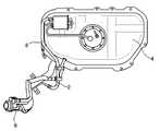
도 1은 본 발명의 적용부위를 나타내기 위한 연료탱크의 평면도로서, 에어 필터(2)는 연료탱크(4)의 상측에서 연료 주입구(6)까지 연결되어 있는 에어호스(8)상에 배치되어 연료 탱크(4) 내부로 유입되는 외부 공기에 포함되어 있는 불순물을 제거하게 된다. 1 is a plan view of a fuel tank for showing an application of the present invention, wherein the air filter 2 is disposed on an
이러한 에어 필터(2)는 도 2에서와 같이, 커넥터(10)와 여과부재(12)로 이루어진다.As shown in FIG. 2, the air filter 2 includes a
상기 커넥터(10)는 일정의 내경을 갖는 원통형 부재로서, 일측단부의 외경부에는 에어 호스(8)의 삽입을 용이하게 하고, 일단 삽입된 에어 호스(8)가 용이하게 빠지지 않게 하기 위한 둘레턱(14)이 형성되고, 타측 단부에는 원주방향 등간격으로 다수의 고정돌기(16)가 형성된다.The
그리고 중간부 외경부에는 경계 둘레턱(18)이 형성되어 양측에서 에어 호스(8)가 삽입될 때, 삽입 범위를 제한하게 된다.In addition, a boundary
상기 여과부재(12)는 원판형으로 이루어지는 고정판(20)의 중심부에 축방향으로 일정 길이의 지지봉(22)이 일체로 형성되고, 이의 지지봉(22)에는 다수의 여과지(24)(26)(28)가 장착된다.The filtering
상기 제1,2,3 여과지(24)(26)(28)를 형성함에 있어서는 유입구측에 위치하는 제1 여과지(24)의 직경이 외경이 제일 작은 상태에서 고정판(20)측으로 갈수록 점진적으로 크게 형성하였다.In forming the first, second and
그리고 상기 고정판(20)은 상기 커넥터(10)의 고정돌기(16)가 삽입 결합될 수 있는 다수의 고정공(30)이 형성되고, 이들 고정공(30) 사이에는 공기가 유출될 수 있는 다수의 유출공(32)이 형성된다.The
또한, 상기 고정판(20)의 외경은 상기 커넥터(10)의 둘레턱(14)과 동일한 외경과 대칭되는 형상으로 이루어져 에어 호스(8)의 삽입과 용이한 이탈을 방지할 수 있도록 구성된다.In addition, the outer diameter of the
상기와 같이 구성되는 커넥터(10)와 여과부재(12)는 도 3에서와 같이 여과부재(12)의 제1,2,3 여과지(24)(26)(28) 부분이 커넥터(10)의 내부로 삽입된 상태에서 커넥터(10)의 고정돌기(16)가 고정판(20)의 고정공(30)에 억지 삽입시켜 결합하면 하나의 에어 필터(2) 조립체가 완성되는 것이다.In the
상기에서 커넥터(10)와 여과부재(12)를 조립식으로 연결함에 있어서는, 여러 가지 방식이 강구될 수 있는데, 억지 끼움 방식과 훅크 방식을 예로 들 수 있다.When the
그러나 본 발명에서는 도 3에서와 같이, 고정돌기(16)의 선단 외주측에 걸림턱(36)을 형성하여 상호 결합시 고정판(20)에 걸리면서 결합이 이루어질 수 있도록 한 것을 도시하고 있다.However, in the present invention, as shown in Figure 3, the
상기와 같이 에어 필터(2)를 형성한 후에 커넥터(10)의 양측으로 에어 호스(8)를 삽입시킨 후 클립(36)으로 고정하면 장착 작업이 완료되는 것이다.After the air filter 2 is formed as described above, the
이와 같이 본 발명의 에어 필터(2)를 에어 호스(8)에 장착할 때에는 제1 여과지(24)가 유입구측에 위치할 수 있도록 연결하면, 도 3의 화살표와 같이 유입되는 외부의 공기가 제1, 2, 3 여과지(24)(26)(28)를 순차적으로 거치면서 여과되어 고정판(20)의 공기 유출공(32)을 통해 유출되어 연료탱크(4)로 유입되는 것이다.As described above, when the air filter 2 of the present invention is attached to the
그리고 에어 필터(2)를 교환할 때에는 에어 필터(2)를 에어 호스(8)에서 탈거한 후에 커넥터(10)와 여과부재(12)를 분리시킨 후 새로운 여과부재(12)만을 결합하여 사용하면 된다.When the air filter 2 is replaced, the air filter 2 is removed from the
이상에서와 같이 본 발명에 의하면, 경량 및 소형화하여 에어 호스상에 탈착이 용이하게 장착함으로써, 교환작업을 용이하게 할 수 있게 된다.As described above, according to the present invention, it is possible to easily replace the work by attaching and detaching on the air hose by reducing the weight and size.
또한, 에어필터의 교환 작업시 여과부재만을 교환할 수 있도록 함으로써, A/S 비용을 절감할 수 있는 발명인 것이다.In addition, it is an invention that can reduce the A / S cost by allowing only the filter member to be replaced during the air filter replacement operation.
Claims (4)
Translated fromKoreanPriority Applications (1)
| Application Number | Priority Date | Filing Date | Title |
|---|---|---|---|
| KR1020060066395AKR101180928B1 (en) | 2006-07-14 | 2006-07-14 | A Fuel Tank of Air Filter For Vehicles |
Applications Claiming Priority (1)
| Application Number | Priority Date | Filing Date | Title |
|---|---|---|---|
| KR1020060066395AKR101180928B1 (en) | 2006-07-14 | 2006-07-14 | A Fuel Tank of Air Filter For Vehicles |
Publications (2)
| Publication Number | Publication Date |
|---|---|
| KR20080006976A KR20080006976A (en) | 2008-01-17 |
| KR101180928B1true KR101180928B1 (en) | 2012-09-07 |
Family
ID=39220571
Family Applications (1)
| Application Number | Title | Priority Date | Filing Date |
|---|---|---|---|
| KR1020060066395AExpired - Fee RelatedKR101180928B1 (en) | 2006-07-14 | 2006-07-14 | A Fuel Tank of Air Filter For Vehicles |
Country Status (1)
| Country | Link |
|---|---|
| KR (1) | KR101180928B1 (en) |
Families Citing this family (2)
| Publication number | Priority date | Publication date | Assignee | Title |
|---|---|---|---|---|
| KR100852524B1 (en)* | 2007-05-09 | 2008-08-14 | 대우조선해양 주식회사 | Automatic closing device of air pipe with opening hole downward |
| KR101897290B1 (en)* | 2012-07-16 | 2018-09-11 | 현대자동차주식회사 | Air filter for vehicle and method for manufacturing thereof |
Citations (1)
| Publication number | Priority date | Publication date | Assignee | Title |
|---|---|---|---|---|
| JP2002346318A (en) | 2001-05-25 | 2002-12-03 | Kondo Harumochi | Air filter |
- 2006
- 2006-07-14KRKR1020060066395Apatent/KR101180928B1/ennot_activeExpired - Fee Related
Patent Citations (1)
| Publication number | Priority date | Publication date | Assignee | Title |
|---|---|---|---|---|
| JP2002346318A (en) | 2001-05-25 | 2002-12-03 | Kondo Harumochi | Air filter |
Also Published As
| Publication number | Publication date |
|---|---|
| KR20080006976A (en) | 2008-01-17 |
Similar Documents
| Publication | Publication Date | Title |
|---|---|---|
| US7556155B2 (en) | Fluid filter and methods | |
| AU2010202546B2 (en) | Fluid filtration apparatus and method | |
| CN104981281B (en) | Filtration devices, especially air filters | |
| US6347712B1 (en) | Filter | |
| KR20200130338A (en) | Fuel filter with coalescer | |
| CA2652904A1 (en) | Tri-flow filter element with venting | |
| KR20150043200A (en) | Filter element and filter system for a liquid medium, in particular diesel fuel | |
| CN110769914B (en) | Filter system comprising a filter element for closing a central tube and an auxiliary element | |
| BR112015025411B1 (en) | LIQUID FILTER ASSEMBLY | |
| US11383186B2 (en) | Filter | |
| JP2004538133A5 (en) | ||
| JP2004538133A (en) | Filter element with drain pipe | |
| KR101180928B1 (en) | A Fuel Tank of Air Filter For Vehicles | |
| WO2019112560A1 (en) | Filter element with barrier | |
| US20060175246A1 (en) | Filter apparatus | |
| JP4374179B2 (en) | Water separation filter | |
| JP2004081996A (en) | Filter device | |
| JP7295601B2 (en) | Filter element cartridge and filtration device | |
| JP4875270B2 (en) | Filter element assembly | |
| JP2006289353A (en) | Filter device | |
| US12233360B2 (en) | Liquid filter | |
| US20200289963A1 (en) | Filtration system with dual lip seal | |
| JPH11197411A (en) | Filter apparatus and element exchange assembly | |
| KR200378939Y1 (en) | oil filter for vehicle | |
| JP2025143212A (en) | Filter Device |
Legal Events
| Date | Code | Title | Description |
|---|---|---|---|
| PA0109 | Patent application | St.27 status event code:A-0-1-A10-A12-nap-PA0109 | |
| PG1501 | Laying open of application | St.27 status event code:A-1-1-Q10-Q12-nap-PG1501 | |
| R18-X000 | Changes to party contact information recorded | St.27 status event code:A-3-3-R10-R18-oth-X000 | |
| PN2301 | Change of applicant | St.27 status event code:A-3-3-R10-R13-asn-PN2301 St.27 status event code:A-3-3-R10-R11-asn-PN2301 | |
| A201 | Request for examination | ||
| PA0201 | Request for examination | St.27 status event code:A-1-2-D10-D11-exm-PA0201 | |
| D13-X000 | Search requested | St.27 status event code:A-1-2-D10-D13-srh-X000 | |
| D14-X000 | Search report completed | St.27 status event code:A-1-2-D10-D14-srh-X000 | |
| E701 | Decision to grant or registration of patent right | ||
| PE0701 | Decision of registration | St.27 status event code:A-1-2-D10-D22-exm-PE0701 | |
| GRNT | Written decision to grant | ||
| PR0701 | Registration of establishment | St.27 status event code:A-2-4-F10-F11-exm-PR0701 | |
| PR1002 | Payment of registration fee | St.27 status event code:A-2-2-U10-U11-oth-PR1002 Fee payment year number:1 | |
| PG1601 | Publication of registration | St.27 status event code:A-4-4-Q10-Q13-nap-PG1601 | |
| PN2301 | Change of applicant | St.27 status event code:A-5-5-R10-R13-asn-PN2301 St.27 status event code:A-5-5-R10-R11-asn-PN2301 | |
| FPAY | Annual fee payment | Payment date:20150831 Year of fee payment:4 | |
| PR1001 | Payment of annual fee | St.27 status event code:A-4-4-U10-U11-oth-PR1001 Fee payment year number:4 | |
| R18-X000 | Changes to party contact information recorded | St.27 status event code:A-5-5-R10-R18-oth-X000 | |
| PR1001 | Payment of annual fee | St.27 status event code:A-4-4-U10-U11-oth-PR1001 Fee payment year number:5 | |
| P22-X000 | Classification modified | St.27 status event code:A-4-4-P10-P22-nap-X000 | |
| PR1001 | Payment of annual fee | St.27 status event code:A-4-4-U10-U11-oth-PR1001 Fee payment year number:6 | |
| FPAY | Annual fee payment | Payment date:20180829 Year of fee payment:7 | |
| PR1001 | Payment of annual fee | St.27 status event code:A-4-4-U10-U11-oth-PR1001 Fee payment year number:7 | |
| R18-X000 | Changes to party contact information recorded | St.27 status event code:A-5-5-R10-R18-oth-X000 | |
| FPAY | Annual fee payment | Payment date:20190827 Year of fee payment:8 | |
| PR1001 | Payment of annual fee | St.27 status event code:A-4-4-U10-U11-oth-PR1001 Fee payment year number:8 | |
| PR1001 | Payment of annual fee | St.27 status event code:A-4-4-U10-U11-oth-PR1001 Fee payment year number:9 | |
| PR1001 | Payment of annual fee | St.27 status event code:A-4-4-U10-U11-oth-PR1001 Fee payment year number:10 | |
| PR1001 | Payment of annual fee | St.27 status event code:A-4-4-U10-U11-oth-PR1001 Fee payment year number:11 | |
| PC1903 | Unpaid annual fee | St.27 status event code:A-4-4-U10-U13-oth-PC1903 Not in force date:20230904 Payment event data comment text:Termination Category : DEFAULT_OF_REGISTRATION_FEE | |
| PC1903 | Unpaid annual fee | St.27 status event code:N-4-6-H10-H13-oth-PC1903 Ip right cessation event data comment text:Termination Category : DEFAULT_OF_REGISTRATION_FEE Not in force date:20230904 |