KR101178505B1 - Substrate for semiconductor device and method for manufacturing the same - Google Patents
Substrate for semiconductor device and method for manufacturing the sameDownload PDFInfo
- Publication number
- KR101178505B1 KR101178505B1KR1020090105515AKR20090105515AKR101178505B1KR 101178505 B1KR101178505 B1KR 101178505B1KR 1020090105515 AKR1020090105515 AKR 1020090105515AKR 20090105515 AKR20090105515 AKR 20090105515AKR 101178505 B1KR101178505 B1KR 101178505B1
- Authority
- KR
- South Korea
- Prior art keywords
- substrate
- film
- single crystal
- semiconductor
- uneven structure
- Prior art date
- Legal status (The legal status is an assumption and is not a legal conclusion. Google has not performed a legal analysis and makes no representation as to the accuracy of the status listed.)
- Expired - Fee Related
Links
Images


Classifications
- H—ELECTRICITY
- H01—ELECTRIC ELEMENTS
- H01L—SEMICONDUCTOR DEVICES NOT COVERED BY CLASS H10
- H01L21/00—Processes or apparatus adapted for the manufacture or treatment of semiconductor or solid state devices or of parts thereof
- H01L21/02—Manufacture or treatment of semiconductor devices or of parts thereof
- H01L21/02104—Forming layers
- H01L21/02365—Forming inorganic semiconducting materials on a substrate
- H01L21/02367—Substrates
- H01L21/0237—Materials
- H—ELECTRICITY
- H01—ELECTRIC ELEMENTS
- H01L—SEMICONDUCTOR DEVICES NOT COVERED BY CLASS H10
- H01L21/00—Processes or apparatus adapted for the manufacture or treatment of semiconductor or solid state devices or of parts thereof
- H01L21/02—Manufacture or treatment of semiconductor devices or of parts thereof
- H01L21/02104—Forming layers
- H01L21/02365—Forming inorganic semiconducting materials on a substrate
- H01L21/02367—Substrates
- H01L21/02428—Structure
- H01L21/0243—Surface structure
- H—ELECTRICITY
- H01—ELECTRIC ELEMENTS
- H01L—SEMICONDUCTOR DEVICES NOT COVERED BY CLASS H10
- H01L21/00—Processes or apparatus adapted for the manufacture or treatment of semiconductor or solid state devices or of parts thereof
- H01L21/02—Manufacture or treatment of semiconductor devices or of parts thereof
- H01L21/02104—Forming layers
- H01L21/02365—Forming inorganic semiconducting materials on a substrate
- H01L21/02436—Intermediate layers between substrates and deposited layers
- H01L21/02439—Materials
- H01L21/02455—Group 13/15 materials
- H01L21/02458—Nitrides
- H—ELECTRICITY
- H01—ELECTRIC ELEMENTS
- H01L—SEMICONDUCTOR DEVICES NOT COVERED BY CLASS H10
- H01L21/00—Processes or apparatus adapted for the manufacture or treatment of semiconductor or solid state devices or of parts thereof
- H01L21/02—Manufacture or treatment of semiconductor devices or of parts thereof
- H01L21/02104—Forming layers
- H01L21/02365—Forming inorganic semiconducting materials on a substrate
- H01L21/02436—Intermediate layers between substrates and deposited layers
- H01L21/02494—Structure
- H—ELECTRICITY
- H01—ELECTRIC ELEMENTS
- H01L—SEMICONDUCTOR DEVICES NOT COVERED BY CLASS H10
- H01L21/00—Processes or apparatus adapted for the manufacture or treatment of semiconductor or solid state devices or of parts thereof
- H01L21/02—Manufacture or treatment of semiconductor devices or of parts thereof
- H01L21/02104—Forming layers
- H01L21/02365—Forming inorganic semiconducting materials on a substrate
- H01L21/02518—Deposited layers
- H01L21/02521—Materials
- H01L21/02538—Group 13/15 materials
- H01L21/0254—Nitrides
Landscapes
- Engineering & Computer Science (AREA)
- Physics & Mathematics (AREA)
- Condensed Matter Physics & Semiconductors (AREA)
- General Physics & Mathematics (AREA)
- Manufacturing & Machinery (AREA)
- Computer Hardware Design (AREA)
- Microelectronics & Electronic Packaging (AREA)
- Power Engineering (AREA)
- Chemical & Material Sciences (AREA)
- Materials Engineering (AREA)
- Led Devices (AREA)
- Crystals, And After-Treatments Of Crystals (AREA)
Abstract
Translated fromKoreanDescription
Translated fromKorean본 발명은 반도체 기판과 이의 제조 방법에 관한 것으로, 보다 상세하게는 각종 파워 소자의 제작 시 기판으로 사용될 수 있는 GaN 막을 구비하는 반도체 기판 및 이의 제조 방법에 관한 것이다.BACKGROUND OF THE
반도체 소자는 반도체 공정 기술을 이용하여 소정의 기판 상에 파워 소자, 발광 소자, 수광 소자 등의 전자 소자를 구현한 전자 부품의 하나이다. 예를 들어, 파워 소자는 기판 상에 트랜지스터, MOSFET, IGBT(Insulated Gate Bipolar Transistor), 숏트키 다이오드 등이 구현되고, 수광 소자는 기판 상에 태양 전지, 포토 센서 등이 구현된다.A semiconductor device is one of electronic components that implements electronic devices such as a power device, a light emitting device, and a light receiving device on a predetermined substrate by using semiconductor processing technology. For example, a power device includes a transistor, a MOSFET, an Insulated Gate Bipolar Transistor (IGBT), a Schottky diode, and the like, and a light receiving device includes a solar cell, a photo sensor, and the like on a substrate.
특히, GaN를 이용한 반도체 발광 소자는 청색 발광이 가능하여 기존에 개발된 GaAs및 InP계 화합물 반도체를 이용한 녹색과 적색 발광 소자와 함께 풀 컬러의 구현을 가능케 하여, 각종 디스플레이의 광원으로 주목받고 있다.In particular, the semiconductor light emitting device using GaN is capable of realizing full color along with green and red light emitting devices using GaAs and InP compound semiconductors, which have been previously developed, and are attracting attention as light sources of various displays.
그러나, 고품위의 GaN 박막을 성장시키기 위해서는 격자 상수 및 열팽창 계수가 동일한 고품위 GaN 단결정 기판이 필요한데, GaN는 융점이 2400℃ 정도이고, 5족 질소의 분압이 3족보다 훨씬 크기 때문에 GaN 단결정 기판을 성장시키기 위해서는 거의 40,000 기압의 질소 압력이 필요하여, 현재의 Si이나 GaAs, InP와 같은 반도체 단결정 성장 기술로는 GaN 단결정 제조가 어려운 것으로 알려져 있다.However, in order to grow a high quality GaN thin film, a high quality GaN single crystal substrate having the same lattice constant and thermal expansion coefficient is required. Since GaN has a melting point of about 2400 ° C. and a partial pressure of
따라서, 현재는 GaN와 격자 상수 및 열팽창 계수의 부정합도가 큰 사파이어(sapphire,α-Al2O3)와 같은 이종 기판을 사용하고, 이를 완화시키기 위하여 AlN나 GaN와같은 완충층을 이용하여 GaN 에피층을 성장시키는 이종 접합 성장법(Heteroepitaxy)을 통해 GaN를 이용한 청색 발광 소자를 제조하고 있다.Therefore, at present, a GaN epitaxial layer using a heterogeneous substrate such as sapphire (α-Al2 O3 ), which has a high mismatch between the lattice constant and the thermal expansion coefficient, is used. A blue light emitting device using GaN is manufactured through a heterojunction growth method (Heteroepitaxy) in which a layer is grown.
그러나, 사파이어 기판의 경우 단결정 GaN 막과 사파이어 기판의 벽개 방향이 서로 달라 우수한 특성의 공진기를 제작하기가 어려울 뿐만 아니라 실리콘과는 달리 단결정 GaN와 사파이어의 결합체는 쉽게 쪼개지지도 않는다는 문제점이 있었다. 그리고, 이종 기판 위에 단결정 GaN의 성장은 기판과의 격자 및 열팽창계수 부정합도의 완화를 위하여 500℃ 내지 600℃의 저온에서 GaN 나노 막대나 AlN 완충층을 반드시 사용하여야 하므로 에피 성장 공정이 복잡해질 뿐만 아니라 후막 성장을 위해 다시 승온시켜야 하는 문제점과 소자 구조의 성장 시 요구되는 InN, GaN 등과 같은 다양한 화합물의 성장을 어렵게 한다.However, in the case of the sapphire substrate, the cleavage directions of the single crystal GaN film and the sapphire substrate are different from each other, making it difficult to fabricate a resonator having excellent characteristics, and unlike silicon, the combination of the single crystal GaN and sapphire is not easily broken. In addition, the growth of single crystal GaN on a heterogeneous substrate is not only complicated by the epitaxial growth process because the GaN nanorod or AlN buffer layer must be used at a low temperature of 500 ° C to 600 ° C to alleviate lattice and thermal expansion mismatch with the substrate. It is difficult to grow a variety of compounds such as InN, GaN, etc., which are required to increase the temperature again for thick film growth and the growth of the device structure.
특히, 사파이어 기판에 성장된 단결정 GaN 막은 격자 상수와 열팽창 계수의 차이에 의한 많은 격자 결함(dislocation density 108 ~109㎝-2)을 지니고 있어서 제작된 파워 소자의 성능이 좋지 않다. 또한, GaN 막을 소정의 두께 이상(7μm 이상)으로 형성할 경우 휨(warpage)이 70μm 이상 발생하여 소자 제작을 위한 후속 공정 특히, 기판 정렬, 포토 공정 및 식각 공정이 어렵게 된다.In particular, the single crystal GaN film grown on the sapphire substrate has many lattice defects (dislocation density 108 to 109 cm-2 ) due to the difference in lattice constant and thermal expansion coefficient, so that the performance of the manufactured power device is not good. In addition, when the GaN film is formed to have a predetermined thickness or more (7 μm or more), warpage occurs at 70 μm or more, thereby making it difficult to perform subsequent processes, particularly substrate alignment, photo process, and etching process, for device fabrication.
이처럼, 종래 기술로는 사파이어 기판과 성장된 단결정 GaN 막의 격자 상수와 열팽창 계수의 차이에 의한 격자 결함과 휨으로 인해 후속 공정에 어려움이 있었다.As described above, in the prior art, there are difficulties in subsequent processes due to lattice defects and warpage due to the difference between the lattice constant and the coefficient of thermal expansion of the sapphire substrate and the grown single crystal GaN film.
본 발명은 상기의 문제점을 해결하기 위해 도출된 것으로, 표면 특성 및 결정성이 우수하여 고성능 반도체 소자 제작에 활용될 수 있도록 한 반도체 기판 및 이의 제조 방법을 제공한다.The present invention has been made to solve the above problems, and provides a semiconductor substrate and a method of manufacturing the same, which can be used for manufacturing a high performance semiconductor device having excellent surface properties and crystallinity.
또한, 본 발명은 후속 반도체 소자 공정에 적용된 상태에서 소자층을 비교적 두껍게 형성하더라도 기판의 휨이 적게 발생됨으로써, 후속 소자 제조 공정이 용이하고 제품 불량률을 최소화할 수 있도록 한 반도체 기판과 이의 제조 방법을 제공한다.In addition, the present invention provides a semiconductor substrate and a method of manufacturing the same to facilitate the subsequent device fabrication process and to minimize the product defect rate by generating less warpage of the substrate even if the device layer is formed relatively thick in the state applied to the subsequent semiconductor device process. to provide.
본 발명의 일 측면에 따른 반도체 기판은, 기판 표면에 형상된 요철 구조; 상기 요철 구조 상에 형성된 침상 구조의 완충층; 상기 완충층 상에 형성되어 상기 요철 구조를 평탄화시켜 형성된 화합물 반도체 막; 및 상기 기판과 상기 화합물 반도체 막 사이에 형성된 다수의 공동; 을 포함한다.According to an aspect of the present invention, a semiconductor substrate includes an uneven structure formed on a surface of a substrate; A buffer layer of a needle-like structure formed on the uneven structure; A compound semiconductor film formed on the buffer layer to planarize the uneven structure; And a plurality of cavities formed between the substrate and the compound semiconductor film; .
상기 요철 구조의 표면 거칠기는 10Å 내지 300Å 범위인 것이 바람직하며, 보다 더 바람직한 범위는 14Å 내지 110Å 범위이다The surface roughness of the uneven structure is preferably in the range of 10 kPa to 300 kPa, and more preferably in the range of 14 kPa to 110 kPa.
상기 공동은 상기 요철 구조의 오목부와 상기 화합물 반도체 막 사이에 형성되는 것이 바람직하다.Preferably, the cavity is formed between the concave portion of the uneven structure and the compound semiconductor film.
상기 오목부는 기판의 결정 형상에 대응하여 형성되는 것이 바람직하다.The recess is preferably formed corresponding to the crystal shape of the substrate.
상기 기판은 사파이어 기판, 실리콘 카바이드 기판, 질화 알류미늄 기판, 산 화 아연 기판 중 어느 하나로 형성되는 것이 바람직하다.The substrate is preferably formed of any one of a sapphire substrate, silicon carbide substrate, aluminum nitride substrate, zinc oxide substrate.
상기 화합물 반도체 막은 GaN, AlN, InN, AlGaN, InGaN 막 중 어느 하나로 형성되는 것이 바람직하다.The compound semiconductor film is preferably formed of any one of a GaN, AlN, InN, AlGaN, InGaN film.
본 발명의 다른 측면에 따른 반도체 기판의 제조 방법은, 기판 표면을 에칭하여 기판의 결정 형상에 대응하는 요철 구조를 형성하는 단계; 상기 요철 구조 상에 침상 구조의 완충층을 형성하는 단계; 및 상기 완충층 상에 화합물 반도체 막을 형성하여 상기 요철 구조를 평탄화하는 단계; 를 포함한다.According to another aspect of the present invention, there is provided a method of manufacturing a semiconductor substrate, the method comprising: forming a concave-convex structure corresponding to the crystal shape of the substrate by etching the substrate surface; Forming a buffer layer of a needle structure on the uneven structure; And forming a compound semiconductor film on the buffer layer to planarize the uneven structure. It includes.
상기 에칭은 상기 기판의 표면 연마를 위한 CMP 공정에서 슬러리의 PH 농도를 높여 실시하는 것이 바람직하다.The etching is preferably performed by increasing the PH concentration of the slurry in the CMP process for polishing the surface of the substrate.
상기 에칭은 상기 기판을 가열한 상태에서 HCl 가스를 흘려 실시하는 것이 바람직하다.It is preferable to perform the said etching by flowing HCl gas in the state which heated the said board | substrate.
상기 에칭은 상기 기판을 KOH 용윰염에 담궈 실시하는 것이 바람직하다.The etching is preferably performed by immersing the substrate in KOH molten salt.
상기 완충층은 상기 기판을 질화 처리하여 상기 기판 상에 완충층을 형성하는 단계와 상기 완충층 중 막질이 약한 부분을 에칭하여 제거하는 단계; 를 반복 실시하여 형성하는 것이 바람직하다.Forming a buffer layer on the substrate by nitriding the substrate, and etching the removed portion of the buffer layer with weak film quality; It is preferable to form by repeatedly performing.
상기 기판은 사파이어 기판, 실리콘 카바이드 기판, 질화 알류미늄 기판, 산화 아연 기판 중 어느 하나로 형성하는 것이 바람직하다.The substrate is preferably formed of any one of a sapphire substrate, a silicon carbide substrate, an aluminum nitride substrate, and a zinc oxide substrate.
상기 화합물 반도체 막은 GaN, AlN, InN, AlGaN, InGaN 막 중 어느 하나로 형성하는 것이 바람직하다.The compound semiconductor film is preferably formed of any one of GaN, AlN, InN, AlGaN, and InGaN films.
본 발명의 실시예에 따른 반도체 기판은 기판의 요철 구조 상에 형성된 침상 구조가 기판과 단결정 GaN 막 사이의 경계면에 공동을 형성하여 격자 부정합에 따른 스트레스를 완화시키고, 관통 전위의 전파를 차단하여 주기 때문에 성장된 단결정 GaN 막은 휨 특성이 적을 뿐만 아니라 결정성 또한 향상된다.In the semiconductor substrate according to the embodiment of the present invention, the needle-like structure formed on the concave-convex structure of the substrate forms a cavity at the interface between the substrate and the single crystal GaN film to relieve stress due to lattice mismatch, and to block propagation of the penetration potential. As a result, the grown single crystal GaN film has not only low warpage characteristics but also improved crystallinity.
또한, 본 발명의 실시예에 따른 반도체 기판은 기판의 요철 구조와 비슷한 형상으로 초기 성장하던 단결정 GaN이 서로 연결됨으로써 3차원 구조에서 2차원 구조로 표면이 평탄화된다.In addition, the semiconductor substrate according to the embodiment of the present invention is planarized from a three-dimensional structure to a two-dimensional structure by connecting the single crystal GaN that was initially grown in a shape similar to the uneven structure of the substrate.
또한, 본 발명의 실시예에 따른 반도체 기판은 기판의 요철 오목부에서 나노 막대가 돌출되면서 더욱 평탄화됨으로써 표면 거칠기가 낮아지고, 이로부터 우수한 경면 특성을 제공한다.In addition, the semiconductor substrate according to the embodiment of the present invention is further flattened by protruding nanorods from the concave-convex concave portion of the substrate to lower the surface roughness, thereby providing excellent mirror surface properties.
또한, 본 발명의 실시예에 따른 반도체 기판은 후속 소자의 제조 공정시 소자층을 비교적 두껍게 형성하더라도 기판의 휨이 적게 발생하기 때문에 기판 척킹, 기판 정렬 등의 기판 핸들링이 용이하다. 따라서, 후속 소자의 제조 공정 예를 들어, 포토 공정, 식각 공정 등을 원활하게 수행할 수 있고, 제품 불량률을 최소화할 수 있다.In addition, the semiconductor substrate according to the embodiment of the present invention is easy to handle the substrate, such as substrate chucking, substrate alignment, since the warpage of the substrate is generated even if the device layer is formed relatively thick in the subsequent manufacturing process. Therefore, a manufacturing process of a subsequent device, for example, a photo process, an etching process, and the like can be smoothly performed, and a product defect rate can be minimized.
이하, 첨부된 도면을 참조하여 본 발명의 실시예를 상세히 설명하기로 한다. 그러나, 본 발명은 이하에서 개시되는 실시예에 한정되는 것이 아니라 서로 다른 다양한 형태로 구현될 것이며, 단지 본 실시예들은 본 발명의 개시가 완전하도록 하며, 통상의 지식을 가진 자에게 발명의 범주를 완전하게 알려주기 위해 제공되는 것이다.Hereinafter, embodiments of the present invention will be described in detail with reference to the accompanying drawings. However, the present invention is not limited to the embodiments disclosed below, but will be implemented in various forms, and only the embodiments are intended to complete the disclosure of the present invention, and to those skilled in the art the scope of the invention. It is provided for complete information.
도면에서 여러 층 및 각 영역을 명확하게 표현하기 위하여 두께를 확대하여 표현하였으며 도면상에서 동일 부호는 동일 요소를 지칭하도록 하였다. 또한, 층, 막, 영역, 판 등의 부분이 다른 부분 "상부에" 또는 "위에" 있다고 표현되는 경우는 각 부분이 다른 부분의 "바로 상부" 또는 "바로 위에" 있는 경우뿐만 아니라 각 부분과 다른 부분의 사이에 또 다른 부분이 있는 경우도 포함한다.In the drawings, the thickness of layers, films, panels, regions, etc., may be exaggerated for clarity, and like reference numerals designate like elements. In addition, when a part such as a layer, a film, an area, or a plate is expressed as “above” or “above” another part, each part is not only when the part is “right above” or “just above” the other part, This includes the case where there is another part between other parts.
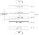
도 1은 본 발명의 실시예에 따른 반도체 기판의 제조 방법을 나타낸 공정 순서도이다. 또한, 도 2 내지 도 8은 발명의 실시예에 따른 반도체 기판의 제조 방법을 설명하기 위한 기판 단면도이다.1 is a process flowchart illustrating a method of manufacturing a semiconductor substrate according to an embodiment of the present invention. 2 to 8 are substrate cross-sectional views illustrating a method of manufacturing a semiconductor substrate in accordance with an embodiment of the present invention.
도 1 내지 도 8을 참조하면, 기판 표면 처리 단계(S110)에서는 준비된 기판의 표면을 에칭하여 기판의 결정 형상에 대응하는 오목부와 이에 대응하여 돌출된 볼룩부를 갖는 요철 구조를 형성한다. 이때, 기판은 사파이어 기판, 실리콘 카바이드(SiC) 기판, 질화 알류미늄(AlN) 기판, 산화 아연(ZnO) 기판 중 어느 하나를 사용할 수 있다.1 to 8, in the substrate surface treatment step S110, the surface of the prepared substrate is etched to form a concave-convex structure having a concave portion corresponding to the crystal shape of the substrate and a protruding ball look portion corresponding thereto. In this case, the substrate may be any one of a sapphire substrate, a silicon carbide (SiC) substrate, an aluminum nitride (AlN) substrate, and a zinc oxide (ZnO) substrate.
본 실시예에서는 사파이어 기판을 사용하는 경우를 예시하여 설명한다. 도 2와 같이, 사파이어 기판(100)은 결정 형상이 육각 형상(Hexagonal Type)을 이루기 때문에 표면 처리 단계를 통해 사파이어 기판(110) 표면에는 육각 형상의 오목부(112)와 이에 대응하여 돌출된 볼록부(111)를 갖는 요철 구조(110)가 형성된다.In this embodiment, a case of using a sapphire substrate will be described by way of example. As shown in FIG. 2, since the
이때, 상기 요철 구조(110)는 사파이어 기판(100)의 표면 연마를 위한 CMP(Chemical Mechanical Polishing) 단계에서 CMP 슬러리의 PH 농도를 높여주어 기판 표면을 에칭하거나, 900℃ 내지 1100℃ 범위의 온도를 갖는 로(furnace)에서 수 초 내지 수 분간 예를 들어, 10분 내지 20분간 HCl 가스를 흘려주어 기판 표면을 에칭하거나, 또는 400℃ 내지 550℃ 범위의 온도를 갖는 KOH 용융염에 담궈 수 분간 예를 들어, 5분 내지 10분간 에칭하여 형성할 수 있다.In this case, the concave-
이를 통해, 사파이어 기판(100) 표면에 10Å 내지 300Å, 더욱 바람직하게는 14Å 내지 110Å의 표면 거칠기(Ra)를 갖는 요철 구조(110)를 형성하게 된다. 이때, 요철 구조(110)의 표면 거칠기가 10Å 미만이면 본 발명에 따른 실시예에서 의도하는 다수의 공동(도 7의 150 참조)이 용이하게 형성되지 않으며, 300Å을 초과하면 다수의 공동이 용이하게 형성되지 않을 뿐만 아니라 이후 표면 평탄화도 쉽게 않아 최종 기판의 표면 거칠기가 현저히 나빠진다. 반면, 일반적인 사파이어 기판은 별도의 에칭 과정이 없기 때문에 대략 3Å 이하의 부드러운 경면 상태를 유지하게 된다.Through this, the
이어, 완충층 형성 단계(S120)에서는 기판 표면에 대한 질화 처리(S121)와 에칭 처리(S122)를 반복 실시하여 기판 표면의 요철 구조(110) 상에 침상 구조 형태의 완충층을 형성한다. 이때, 완충층은 다양한 물질로 형성할 수 있으며, 본 실시예에서는 후속 형성될 단결정 GaN 막과의 격자 계수차가 적은 AlN으로 형성하는 경우를 예시한다. 이를 위해, 암모니아 분위기 속에서 질소 가스를 공급하여 사파이어 기판(100)의 표면을 질화 처리하고(S121), 이어 HCl을 공급하여 질화 처리된 질화막 중 약한 부분을 에칭하여 제거한다(S122). 이후, HCl의 공급을 차단하고(혹 은 공급량을 줄여서) 다시 사파이어 기판(100)의 표면을 질화 처리한 후 다시 HCl을 공급하여 질화 처리된 질화막 중 약한 부분을 에칭하여 제거한다.Subsequently, in the buffer layer forming step S120, nitriding treatment (S121) and etching treatment (S122) are repeatedly performed on the substrate surface to form a buffer layer having a needle-like structure on the
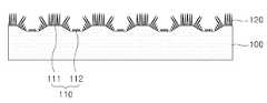
도 3과 같이, 질화 처리(S121) 및 에칭 처리(S122)를 수회 반복 실시하면 막질이 약한 부분은 막질이 강한 부분에 비해 상대적으로 성장 속도가 느려지기 때문에 완충층(120)은 끝이 뾰족한 침상 구조로 성장하게 된다. 또한, 본 실시예의 경우는 사파이어 기판(100)을 사용함에 따라 사파이어 기판(100)의 'Al'과 질소 가스의 'N'이 반응하여 사파이어 기판(100) 상에 AIN 완충층(120)을 형성하게 된다. 이러한 AIN 완충층(120)은 후속공정인 단결정 GaN 막 성장 시 발생하는 격자 부정합에 따른 크랙(crack)을 억제하는 역할과 동시에 침상 구조를 이루어 사파이어 기판(110)의 요철 오목부(112) 상에서 단결정 GaN 막이 성장하는 것을 공간적으로 제한함으로써 사파이어 기판(110)의 요철 오목부(112) 상에 다수의 미세 공동(void)을 형성시키는 역할을 한다.As shown in FIG. 3, when the nitriding treatment (S121) and the etching treatment (S122) are repeatedly performed, the
이어, 씨드층 형성 단계(S130)에서는 HCl 가스와 질소 가스가 섞인 혼합 가스와 암모니아 가스와 질소 가스가 섞인 혼합 가스를 각각 흘려주어 갈륨 금속과 HCl 가스가 반응하여 생성된 GaCl 가스와 암모니아 가스에서 열분해된 N원자가 반응하여 생성된 GaN이 AlN 완충층(120)이 형성된 사파이어 기판(110) 표면에서 성장되도록 하였다. 이에 따라, 도 4와 같이, 침상 구조의 AlN 완충층(120)은 보다 조대한 원뿔 형태로 성장하면서 씨드층(130)을 형성하게 되고, 씨드층(130)의 원뿔 끝단에도 나노 막대(131)가 형성된다.Subsequently, in the seed layer forming step (S130), a mixed gas containing HCl gas and nitrogen gas and a mixed gas containing ammonia gas and nitrogen gas are respectively flowed to thermally decompose GaCl gas and ammonia gas generated by reacting gallium metal and HCl gas. GaN generated by reacting the N atoms was grown on the surface of the
이후, GaN 막 형상 단계(S140)에서는 씨드층(130)을 중심으로 사파이어 기 판(100) 상에 단결정 GaN 막(140a 내지 140d)을 소정 두께만큼 성장시켜 사파이어 기판(100)의 표면을 평탄화시킨다. 도 5 내지 도 8은 증착 시간의 증가에 따른 단결정 GaN 막의 성장 과정을 나타낸 것으로, 도 5와 같이 증착 초기에 사파이어 기판(100)의 요철 볼록부(111) 상에 형성된 씨드층의 나노 막대(도 4의 131)를 중심으로 성장하여 요철 형태로 분리되었던 단결정 GaN 막(140a)은 수직 성장보다 측면 성장이 우세하게 일어나면서 증착 시간이 지남에 따라 오목한 부분이 메꿔지면서 서로 연결되어 도 8과 같이 평탄화된다. 이러한 평탄화 과정에서 도 5와 같이 사파이어 기판(100)의 요철 오목부(112) 상에는 공동(150)이 형성되고, 평탄화가 진행됨에 따라 도 6과 같이 사파이어 기판(100)의 요철 오목부(112)에 형성되었던 침상 구조의 끝단에서도 나노 막대(132)가 성장된다. 또한, 상기 나노 막대(132)는 씨드층으로 기능하여 계속적인 평탄화 과정에서 사파이어 기판(100)의 요철 구조의 단차 즉, 볼록부(111)와 오목부(112)와 높이 차이를 해소하는 역할을 하여 줌으로써 표면 특성 즉, 경면 특성을 향상시키는 역할과 공동(150)을 유지시키는 역할을 한다.Subsequently, in the GaN film forming step S140, the surface of the
한편, 본 발명의 실시예에 따른 반도체 기판의 특성을 알아보기 위하여, 실험예와 비교예를 들어 설명하면 다음과 같다. 상기 실험예는 전술한 제조 방법에 따라 사파이어 기판 상에 요철 구조를 형성하고, 요철 구조 상에 나노 구조의 AlN 완충층을 형성하고, 나노 막대 형상의 씨드층을 형성한 후, 대략 10분간 단결정 GaN 막을 10㎛ 내지 18㎛의 두께로 성장시켰다. 반면, 상기 비교예는 사파이어 기판 상에 AlN 완충층을 바로 형성한 후 단결정 GaN 막을 10㎛ 내지 18㎛의 두께로 성장시켰다.On the other hand, in order to find out the characteristics of the semiconductor substrate according to an embodiment of the present invention, it will be described with reference to the experimental example and the comparative example. In the above experimental example, the uneven structure was formed on the sapphire substrate according to the above-described manufacturing method, the nanostructured AlN buffer layer was formed on the uneven structure, the nanorod-shaped seed layer was formed, and then a single crystal GaN film was formed for about 10 minutes. It was grown to a thickness of 10 μm to 18 μm. On the other hand, in the comparative example, the AlN buffer layer was directly formed on the sapphire substrate, and the single crystal GaN film was grown to a thickness of 10 μm to 18 μm.
도 9는 본 발명의 비교예에 따른 단결정 GaN 막의 원자 현미경(Atomic Force Microscope;AFM) 사진이고, 도 10은 본발명의 실험예에 따른 단결정 GaN 막의 원자 현미경 사진이다.9 is an atomic force microscope (AFM) photograph of a single crystal GaN film according to a comparative example of the present invention, and FIG. 10 is an atomic microscope picture of a single crystal GaN film according to an experimental example of the present invention.
도 9와 도 10을 비교해보면, AFM 사진 상으로도 본 발명의 실험예에 따른 단결정 GaN 막의 표면이 훨씬 매끄러움을 알 수 있으며, 실제 표면 거칠기를 측정하더라도 본 발명의 비교예에 따른 단결정 GaN 막은 표면 거칠기(Ra)가 대략 약 2218Å인 반면에 본 발명의 실험예에 따른 단결정 GaN 막은 표면 거칠기(Ra)가 대략 5Å 정도여서 표면 거칠기 특성이 상당 수준 향상되었음을 알 수 있었다.9 and 10, the surface of the single crystal GaN film according to the experimental example of the present invention is much smoother even on the AFM image. Even though the actual surface roughness is measured, the single crystal GaN film according to the comparative example of the present invention While the roughness Ra was about 2218 GPa, the single crystal GaN film according to the experimental example of the present invention had a surface roughness Ra of about 5 GPa, indicating that the surface roughness characteristics were significantly improved.
도 11은 본 발명의 비교예에 따른 단결정 GaN 막의 (002)면 로킹 커브(rocking curve) 측정 그래프이고, 도 12는 본 발명의 실험예에 따른 단결정 GaN 막의 (002)면 로킹 커브 측정 그래프이다. 또한, 도 13은 본 발명의 비교예에 따른 단결정 GaN 막의 (102)면 로킹 커브 측정 그래프이고, 도 14는 본 발명의 실험예에 따른 단결정 GaN 막의 (102)면 로킹 커브 측정 그래프이다.FIG. 11 is a graph illustrating a (002) plane rocking curve measurement of a single crystal GaN film according to a comparative example of the present invention, and FIG. 12 is a graph illustrating a (002) plane rocking curve measurement of a single crystal GaN film according to an experimental example of the present invention. 13 is a graph of (102) plane rocking curve measurement of a single crystal GaN film according to a comparative example of the present invention, and FIG. 14 is a graph of measurement of (102) plane rocking curve of a single crystal GaN film according to an experimental example of the present invention.
도 11을 참고하면, 본 발명의 비교예에 따른 단결정 GaN 막의 (002)면에 대한 피크 반치값은 553arcsec인 반면, 도 12를 참조하면 본 발명의 실험예에 따른 단결정 GaN 막의 (002)면에 대한 피크 반치값은 331rcsec로, 대략 60% 정도의 결정성이 향상되었음을 보여준다. 또한, 도 13을 참고하면, 본 발명의 비교예에 따른 단결정 GaN 막의 (102)면에 대한 피크 반치값은 509arcsec인 반면, 도 14를 참조하면 본 발명의 실험예에 따른 단결정 GaN 막의 (102)면에 대한 피크 반치값은 241arcsec로, 대략 47% 정도의 결정성이 향상되었음을 보여준다.Referring to FIG. 11, the peak half value of the (002) plane of the single crystal GaN film according to the comparative example of the present invention is 553 arcsec, whereas with reference to FIG. 12, the peak half value of the single crystal GaN film of the single crystal GaN film according to the experimental example of the present invention The peak half-value for the 331 rcsec shows an improvement in crystallinity of about 60%. Referring to FIG. 13, the peak half value of the (102) plane of the single crystal GaN film according to the comparative example of the present invention is 509 arcsec, while referring to FIG. 14, the (102) of the single crystal GaN film according to the experimental example of the present invention. The peak half value for the surface is 241 arcsec, showing an improvement of approximately 47% crystallinity.
도 15는 본 발명의 비교예에 따른 단결정 GaN 막을 갖는 반도체 기판의 휨 특성을 측정한 그래프이고, 도 16은 본 발명의 실험예에 따른 단결정 GaN 막을 갖는 반도체 기판의 휨 특성을 측정한 그래프이다.FIG. 15 is a graph measuring warpage characteristics of a semiconductor substrate having a single crystal GaN film according to a comparative example of the present invention, and FIG. 16 is a graph measuring warpage characteristics of a semiconductor substrate having a single crystal GaN film according to an experimental example of the present invention.
도 15를 참고하면, 본 발명의 비교예에 따른 단결정 GaN 막을 갖는 반도체 기판은 휨 값(Bow)이 65.10㎛인 반면에, 도 16을 참고하면, 본 발명의 실험예에 따른 단결정 GaN 막을 갖는 반도체 기판은 휨 값(Bow)이 37.33㎛이어서 대략 57% 정도로 기판의 휨 특성이 적음을 알 수 있었다.Referring to FIG. 15, a semiconductor substrate having a single crystal GaN film according to a comparative example of the present invention has a warpage value of 65.10 μm, while referring to FIG. 16, a semiconductor having a single crystal GaN film according to an experimental example of the present invention. The substrate had a warpage value of 37.33 占 퐉, indicating that the substrate had less warpage characteristics of about 57%.
이처럼, 본 발명의 실시예에 따른 반도체 기판은 기판의 요철 구조 상에 형성된 침상 구조가 기판과 단결정 GaN 막 사이의 경계면에 공동을 형성하여 격자 부정합에 따른 스트레스를 완화시키고, 관통 전위의 전파를 차단하여 주기 때문에 성장된 단결정 GaN 막은 휨 특성이 적을 뿐만 아니라 결정성 또한 향상된다. 또한, 기판의 요철 구조과 비슷한 형상으로 초기 성장하던 단결정 GaN이 서로 연결되어 3차원에서 2차원으로 표면이 평탄화되고, 요철 구조의 오목부에서 나노 막대가 돌출되면서 더욱 평탄화됨으로써 표면 거칠기가 낮아진다.As described above, in the semiconductor substrate according to the embodiment of the present invention, the needle-like structure formed on the uneven structure of the substrate forms a cavity at the interface between the substrate and the single crystal GaN film to relieve stress due to lattice mismatch and to block propagation of the penetration potential. Therefore, the grown single crystal GaN film not only has low warpage characteristics but also improves crystallinity. In addition, the single crystal GaN, which was initially grown in a shape similar to the uneven structure of the substrate, is connected to each other to planarize the surface in three to two dimensions, and further flatten by protruding nanorods from the concave portion of the uneven structure, thereby lowering the surface roughness.
그리고, 본 실시예에서는 반도체 화합물 막 중에서 범용성이 높은 단결정 GaN 막을 형성하여 반도체 기판을 제작하는 경우를 예시하였으나, 사용 목적에 따라 전술한 단결정 GaN 막 대신에 다양한 반도체 화합물 막 예를 들어, AlN, InN, AlGaN, InGaN 막 중 적어도 어느 하나로 반도체 기판을 제작할 수 있으며, 이 경우에도 전술한 실험예와 유사한 실험 결과를 얻을 수 있었다.In the present embodiment, the semiconductor substrate is fabricated by forming a highly versatile single crystal GaN film in the semiconductor compound film, but various semiconductor compound films such as AlN and InN may be used instead of the above-described single crystal GaN film according to the purpose of use. The semiconductor substrate may be fabricated using at least one of AlGaN, InGaN, and in this case, experimental results similar to those of the above-described experimental example may be obtained.
한편, 본 발명에 따른 반도체 기판은 다양한 반도체 소자의 제조를 위해 사용될 수 있다. 하기에서는, 이러한 가능성의 일 예로 전술한 반도체 기판 상에 다양한 전자 소자가 형성된 반도체 소자에 대하여 설명한다. 이때, 전술한 실시예와 중복되는 설명은 생략하거나 간략히 설명한다.On the other hand, the semiconductor substrate according to the present invention can be used for the manufacture of various semiconductor devices. Hereinafter, as an example of such a possibility, a semiconductor device in which various electronic devices are formed on the semiconductor substrate described above will be described. In this case, a description overlapping with the above-described embodiment will be omitted or briefly described.
도 17은 본 발명에 따른 반도체 기판을 구비하는 반도체 소자의 단면도이다.17 is a cross-sectional view of a semiconductor device having a semiconductor substrate according to the present invention.
도 17을 참조하면, 상기 반도체 소자는, 볼록부(211a)와 오목부(211b)로 이루어진 요철 구조(211)의 기판(210), 상기 기판(210)의 요철 구조(211) 상에 형성된 침상 구조의 완충층(미도시)과, 상기 완충층(미도시) 상에 형성되어 상기 요철 구조를 평탄화시켜주는 단결정 GaN 막(220)을 구비하는 소자층(300)을 포함한다. 이러한 반도체 소자는 상기 소자층(300)에 전기 에너지를 광 에너지로 변환하는 적어도 하나의 발광 소자(L)가 마련되어 광원 모듈에 사용될 수 있다.Referring to FIG. 17, the semiconductor device may include a
기판(210)은 전술한 사파이어 기판을 사용하며, 표면 에칭을 실시하여 10Å 내지 300Å의 표면 거칠기를 갖는 요철 구조(211)가 형성된다.The
완충충(미도시)은 앞선 실시예의 도 2에서 설명한 바와 같이, 질화 처리를 통해 기판(210)의 요철 구조(211) 상에 AIN 막을 형성한 후 에칭 공정을 통해 막질이 약한 부분을 제거하는 방식으로, 질화 처리와 에칭 처리를 수회 반복 실시하여 침상 구조(도 2의 120)로 형성한다.As described above with reference to FIG. 2 of the previous embodiment, the buffer layer forms an AIN film on the
소자층(300)은 상기 완충충의 침상 구조 및 기판(210)의 요철 구조(211)를 평탄화시키기에 충분한 두께의 단결정 GaN 막(220)을 포함하며, 평탄화 과정에서 상기 GaN 막(220)과 상기 기판(210)의 요철 오목부(211b) 사이에 형성된 다수의 공동(212)을 포함한다. 이러한 공동(212)과 AiN 완충층이 기판(210)과 단결정 GaN 막(220) 사이의 격자 부정합에 따른 스트레스를 완화시키고, 관통 전위의 전파를 차단하여 주기 때문에 성장된 단결정 GaN 막(220)은 휨 특성이 적을 뿐만 아니라 결정성 또한 향상될 수 있다.The
한편, 상기 소자층(300)에는 적어도 하나의 발광 소자(L)가 마련된다. 예를 들어, 상기 발광 소자는 n형층(231), 활성층(232), p형층(233)을 구비하는 반도체층과, 상기 n형층(231)의 일부 영역에 형성된 제 1 전극(234) 및 상기 p형층(233)의 일부 영역에 형성된 제 2 전극(235)을 포함한다. 이때, n형층(231), 활성층(232), p형층(233) 중 어느 하나 예를 들어, n형층(231)은 하부의 단결정 GaN 막(220)을 이용하여 형성할 수음은 물론이다.Meanwhile, at least one light emitting device L is provided in the
상기 n형층(231), 활성층(232) 및 p형층(233)은 Si, GaN, AlN, InGaN, AlGaN, AlInGaN 중 적어도 어느 하나를 포함하는 반도체 박막으로 형성하는 것이 바람직하다. 한편, 예를 들어, 본 실시예에서는 n형층(231) 및 p형층(233)은 GaN 박막으로 형성되고, 활성층(232)은 InGaN 박막으로 형성된다. 상기 n형층(231)은 전자를 제공하는 층으로서, 전술한 반도체 박막에 n형 도펀트 예를 들어, Si, Ge, Se, Te, C 등을 주입하여 형성할 수 있다. 상기 p형층(233)은 정공을 제공하는 층으로서, 상기의 반도체 박막에 p형 도펀트 예를 들어, Mg, Zn, Be, Ca, Sr, Ba 등을 주입하여 형성할 수 있다. 상기 활성층(232)은 n형층(231)에서 제공된 전자와 p형층(233)에서 제공된 정공이 재결합되면서 소정 파장의 광을 출력하는 층으로서, 우물층(well layer)과 장벽층(barrier layer)을 교대로 적층하여 단일 양자 우물 구조 또는 다중 양자 우물 구조(multiple quantum well) 구조를 갖는 다층의 반도체 박막으로 형성할 수 있다. 이러한 활성층(332)을 이루는 반도체 재료에 따라 출력되는 광의 파장이 변화되므로, 목표로 하는 출력 파장에 따라 적절한 반도체 재료를 선택하는 것이 바람직하다.The n-
이와 같은 반도체 소자는 결정성 및 표면 특성이 좋은 GaN 막 상에 형성되기 때문에 고속 동작 및 안정성이 우수할 뿐만 아니라, 기판(210) 상에 소자층(430)을 형성하는 과정에서 기판(210)의 변형 특히, 휨 현상이 적게 발생한다. 따라서, 후속 공정에서 기판 척킹, 기판 정렬 등 기판의 핸들링이 용이하므로, 종래와 같은 수율 저하 및 불량 증가의 문제점이 발생하지 않는다.Since the semiconductor device is formed on a GaN film having good crystallinity and surface properties, the semiconductor device may not only be excellent in high speed operation and stability, but also may be formed in the process of forming the device layer 430 on the
한편, 상기에서 전술한 반도체 소자는 기판(210) 표면에 요철 구조(211)를 형성한 후 상기 요철 구조(211) 상에 침상 구조의 완충층(미도시)을 형성하고, 상기 침상 구조 상에 단결정 GaN 막(220)을 형성한 후 발광 소자(L)를 형성하였으나, 본 발명은 이에 한정되지 않으며, 상기 기판(210) 상에는 발광 소자(L)의 이외의 다양한 파워 소자 예를 들어, 트랜지스터, 태양 전지, MOSFET, 숏트키 다이오드, 포토 센서 등을 형성할 수도 있다.Meanwhile, in the above-described semiconductor device, after the
이상, 본 발명에 대하여 전술한 실시예 및 첨부된 도면을 참조하여 설명하였으나, 본 발명은 이에 한정되지 않으며, 후술되는 특허청구범위에 의해 한정된다. 따라서, 본 기술분야의 통상의 지식을 가진 자라면 후술되는 특허청구범위의 기술 적 사상에서 벗어나지 않는 범위 내에서 본 발명이 다양하게 변형 및 수정될 수 있음을 알 수 있을 것이다.As mentioned above, although this invention was demonstrated with reference to the above-mentioned Example and an accompanying drawing, this invention is not limited to this, It is limited by the following claims. Therefore, it will be apparent to those skilled in the art that the present invention may be variously modified and modified without departing from the technical spirit of the following claims.
도 1은 본 발명의 실시예에 따른 반도체 기판의 제조 방법을 나타낸 공정 순서도.1 is a process flowchart showing a method of manufacturing a semiconductor substrate according to an embodiment of the present invention.
도 2 내지 도 8은 발명의 실시예에 따른 반도체 기판의 제조 방법을 설명하기 위한 기판 단면도.2 to 8 are substrate cross-sectional views for explaining a method for manufacturing a semiconductor substrate according to the embodiment of the present invention.
도 9는 본 발명의 비교예에 따른 단결정 GaN 막의 원자 현미경 사진.9 is an atomic micrograph of a single crystal GaN film according to a comparative example of the present invention.
도 10은 본발명의 실험예에 따른 단결정 GaN 막의 원자 현미경 사진.10 is an atomic micrograph of a single crystal GaN film according to an experimental example of the present invention.
도 11은 본 발명의 비교예에 따른 단결정 GaN 막의 (002)면 로킹 커브 그래프.11 is a (002) plane rocking curve graph of a single crystal GaN film according to a comparative example of the present invention.
도 12는 본 발명의 실험예에 따른 단결정 GaN 막의 (002)면 로킹 커브 그래프.12 is a (002) plane rocking curve graph of a single crystal GaN film according to an experimental example of the present invention.
도 13은 본 발명의 비교예에 따른 단결정 GaN 막의 (102)면 로킹 커브 그래프.13 is a (102) plane rocking curve graph of a single crystal GaN film according to a comparative example of the present invention.
도 14는 본 발명의 실험예에 따른 단결정 GaN 막의 (102)면 로킹 커브 그래프.14 is a (102) plane rocking curve graph of a single crystal GaN film according to an experimental example of the present invention.
도 15는 본 발명의 비교예에 따른 단결정 GaN 막을 갖는 반도체 기판의 휨 특성을 측정한 그래프.15 is a graph measuring the warpage characteristics of a semiconductor substrate having a single crystal GaN film according to a comparative example of the present invention.
도 16은 본 발명의 실험예에 따른 단결정 GaN 막을 갖는 반도체 기판의 휨 특성을 측정한 그래프.Fig. 16 is a graph measuring the bending characteristics of a semiconductor substrate having a single crystal GaN film according to an experimental example of the present invention.
도 17은 본 발명에 따른 반도체 기판을 구비하는 반도체 소자의 단면도.17 is a cross-sectional view of a semiconductor device having a semiconductor substrate according to the present invention.
<도면의 주요 부분에 대한 부호의 설명><Explanation of symbols for the main parts of the drawings>
100: 기판 110: 요철100: substrate 110: irregularities
120: 완충층 130: 씨드층120: buffer layer 130: seed layer
140: GaN 막 150: 공동140: GaN film 150: cavity
210: 기판 211: 요철210: substrate 211: unevenness
220: GaN 막 231: n형층220: GaN film 231: n-type layer
232: 활성층 233: p형층232: active layer 233: p-type layer
234: 제 1 전극 235: 제 2 전극234: first electrode 235: second electrode
300: 소자층300: element layer
Claims (13)
Translated fromKoreanPriority Applications (2)
| Application Number | Priority Date | Filing Date | Title |
|---|---|---|---|
| KR1020090105515AKR101178505B1 (en) | 2009-11-03 | 2009-11-03 | Substrate for semiconductor device and method for manufacturing the same |
| US12/917,970US20110101307A1 (en) | 2009-11-03 | 2010-11-02 | Substrate for semiconductor device and method for manufacturing the same |
Applications Claiming Priority (1)
| Application Number | Priority Date | Filing Date | Title |
|---|---|---|---|
| KR1020090105515AKR101178505B1 (en) | 2009-11-03 | 2009-11-03 | Substrate for semiconductor device and method for manufacturing the same |
Publications (2)
| Publication Number | Publication Date |
|---|---|
| KR20110048795A KR20110048795A (en) | 2011-05-12 |
| KR101178505B1true KR101178505B1 (en) | 2012-09-07 |
Family
ID=43924420
Family Applications (1)
| Application Number | Title | Priority Date | Filing Date |
|---|---|---|---|
| KR1020090105515AExpired - Fee RelatedKR101178505B1 (en) | 2009-11-03 | 2009-11-03 | Substrate for semiconductor device and method for manufacturing the same |
Country Status (2)
| Country | Link |
|---|---|
| US (1) | US20110101307A1 (en) |
| KR (1) | KR101178505B1 (en) |
Families Citing this family (9)
| Publication number | Priority date | Publication date | Assignee | Title |
|---|---|---|---|---|
| JP5277270B2 (en)* | 2010-07-08 | 2013-08-28 | 学校法人立命館 | Crystal growth method and semiconductor device |
| TWI456791B (en)* | 2011-01-20 | 2014-10-11 | Hon Hai Prec Ind Co Ltd | Semiconductor light-emitting chip and method of manufacturing same |
| JP5059205B2 (en)* | 2011-03-03 | 2012-10-24 | 株式会社東芝 | Wafer and crystal growth method |
| KR101259999B1 (en)* | 2011-04-28 | 2013-05-06 | 서울옵토디바이스주식회사 | Semiconductor substrate and method of fabricating the same |
| KR101420265B1 (en)* | 2011-10-21 | 2014-07-21 | 주식회사루미지엔테크 | Method of manufacturing a substrate |
| WO2016099494A1 (en)* | 2014-12-17 | 2016-06-23 | Intel Corporation | Integrated circuit die having reduced defect group iii-nitride layer and methods associated therewith |
| KR102351100B1 (en)* | 2015-06-16 | 2022-01-14 | 쑤저우 레킨 세미컨덕터 컴퍼니 리미티드 | Light-emitting diode and method for manufacturing same |
| JP6995304B2 (en)* | 2016-12-06 | 2022-01-14 | 株式会社サイオクス | Nitride semiconductor template manufacturing method, nitride semiconductor template and nitride semiconductor device |
| KR102704073B1 (en)* | 2022-01-17 | 2024-09-05 | 고려대학교 산학협력단 | GaN semiconductor structure and method for selective growth thereof |
Citations (3)
| Publication number | Priority date | Publication date | Assignee | Title |
|---|---|---|---|---|
| US20030224548A1 (en) | 2002-01-30 | 2003-12-04 | Kazutaka Terashima | Method of forming group-III nitride semiconductor layer on a light-emitting device |
| JP2005057064A (en) | 2003-08-05 | 2005-03-03 | Toyoda Gosei Co Ltd | Group III nitride semiconductor layer and growth method thereof |
| US20090183774A1 (en) | 2007-07-13 | 2009-07-23 | Translucent, Inc. | Thin Film Semiconductor-on-Sapphire Solar Cell Devices |
Family Cites Families (4)
| Publication number | Priority date | Publication date | Assignee | Title |
|---|---|---|---|---|
| JP4781599B2 (en)* | 2002-09-05 | 2011-09-28 | 日本碍子株式会社 | Epitaxial substrate and multilayer structure |
| JP2009519202A (en)* | 2005-12-12 | 2009-05-14 | キーマ テクノロジーズ, インク. | Group III nitride product and method for producing the same |
| KR101338698B1 (en)* | 2007-04-16 | 2013-12-06 | 엘지이노텍 주식회사 | Nitride semiconductor light emitting device |
| JP2009081406A (en)* | 2007-09-27 | 2009-04-16 | Showa Denko Kk | Group III nitride semiconductor light emitting device, method for manufacturing the same, and lamp |
- 2009
- 2009-11-03KRKR1020090105515Apatent/KR101178505B1/ennot_activeExpired - Fee Related
- 2010
- 2010-11-02USUS12/917,970patent/US20110101307A1/ennot_activeAbandoned
Patent Citations (3)
| Publication number | Priority date | Publication date | Assignee | Title |
|---|---|---|---|---|
| US20030224548A1 (en) | 2002-01-30 | 2003-12-04 | Kazutaka Terashima | Method of forming group-III nitride semiconductor layer on a light-emitting device |
| JP2005057064A (en) | 2003-08-05 | 2005-03-03 | Toyoda Gosei Co Ltd | Group III nitride semiconductor layer and growth method thereof |
| US20090183774A1 (en) | 2007-07-13 | 2009-07-23 | Translucent, Inc. | Thin Film Semiconductor-on-Sapphire Solar Cell Devices |
Also Published As
| Publication number | Publication date |
|---|---|
| KR20110048795A (en) | 2011-05-12 |
| US20110101307A1 (en) | 2011-05-05 |
Similar Documents
| Publication | Publication Date | Title |
|---|---|---|
| KR101178505B1 (en) | Substrate for semiconductor device and method for manufacturing the same | |
| KR101321654B1 (en) | Substrate for growing group-iii nitride semiconductors, epitaxial substrate for group-iii nitride semiconductors, group-iii nitride semiconductor element, stand-alone substrate for group-iii nitride semiconductors, and methods for manufacturing the preceding | |
| Krost et al. | GaN‐based devices on Si | |
| US7811902B2 (en) | Method for manufacturing nitride based single crystal substrate and method for manufacturing nitride based light emitting diode using the same | |
| TWI447959B (en) | Method of manufacturing a nitride semiconductor crystal layer | |
| EP0551721B1 (en) | Gallium nitride base semiconductor device and method of fabricating the same | |
| CN101427391B (en) | Nitride semiconductor component and manufacturing process thereof | |
| JP5244487B2 (en) | Gallium nitride growth substrate and method for manufacturing gallium nitride substrate | |
| CN103733308A (en) | Nitride semiconductor structure and method of fabricating same | |
| CN103531612A (en) | Semiconductor device | |
| JP2011016680A (en) | Method for manufacturing group iii nitride semiconductor free-standing substrate, group iii nitride semiconductor free-standing substrate, and method for manufacturing group iii nitride semiconductor device, and group iii nitride semiconductor device | |
| KR101246832B1 (en) | Non-polar or Semi-polar Group III-Nitride Based Light Emitting Diode and Fabrication Method Thereof | |
| US7135716B2 (en) | Gallium nitride-based semiconductor light-emitting device | |
| WO2014068838A1 (en) | Epitaxial wafer and method for manufacturing same | |
| WO2005088687A1 (en) | Method for manufacturing gallium nitride semiconductor substrate | |
| CN113539786A (en) | Silicon-based gallium nitride epitaxial structure and preparation method thereof | |
| JP6117821B2 (en) | Composite substrate and functional element | |
| Kane et al. | Gallium nitride (GaN) on silicon substrates for LEDs | |
| JP4786587B2 (en) | Group III nitride semiconductor and method for manufacturing the same, substrate for manufacturing group III nitride semiconductor | |
| JP4583523B2 (en) | III-V nitride semiconductor light emitting device and method for manufacturing the same | |
| KR100793443B1 (en) | Nitride-based compound semiconductor substrate structure and its manufacturing method | |
| KR101384071B1 (en) | Nitride semiconductor substrate, method for fabricating the substrate and light emitting diode including the substrate | |
| JP2010251743A (en) | Group III nitride semiconductor growth substrate, group III nitride semiconductor free-standing substrate, group III nitride semiconductor device, and methods of manufacturing the same | |
| Bessolov et al. | Semipolar Wide-Band III–N-Layers on a Silicon Substrate: Orientation Controlling Epitaxy and the Properties of Structures | |
| CN109378368B (en) | Method for epitaxial growth of GaN substrate on PSS substrate along semi-polar surface |
Legal Events
| Date | Code | Title | Description |
|---|---|---|---|
| A201 | Request for examination | ||
| PA0109 | Patent application | St.27 status event code:A-0-1-A10-A12-nap-PA0109 | |
| PA0201 | Request for examination | St.27 status event code:A-1-2-D10-D11-exm-PA0201 | |
| E902 | Notification of reason for refusal | ||
| PE0902 | Notice of grounds for rejection | St.27 status event code:A-1-2-D10-D21-exm-PE0902 | |
| PG1501 | Laying open of application | St.27 status event code:A-1-1-Q10-Q12-nap-PG1501 | |
| E13-X000 | Pre-grant limitation requested | St.27 status event code:A-2-3-E10-E13-lim-X000 | |
| P11-X000 | Amendment of application requested | St.27 status event code:A-2-2-P10-P11-nap-X000 | |
| P13-X000 | Application amended | St.27 status event code:A-2-2-P10-P13-nap-X000 | |
| PE0902 | Notice of grounds for rejection | St.27 status event code:A-1-2-D10-D21-exm-PE0902 | |
| P11-X000 | Amendment of application requested | St.27 status event code:A-2-2-P10-P11-nap-X000 | |
| P13-X000 | Application amended | St.27 status event code:A-2-2-P10-P13-nap-X000 | |
| E701 | Decision to grant or registration of patent right | ||
| PE0701 | Decision of registration | St.27 status event code:A-1-2-D10-D22-exm-PE0701 | |
| GRNT | Written decision to grant | ||
| PR0701 | Registration of establishment | St.27 status event code:A-2-4-F10-F11-exm-PR0701 | |
| PR1002 | Payment of registration fee | St.27 status event code:A-2-2-U10-U11-oth-PR1002 Fee payment year number:1 | |
| PG1601 | Publication of registration | St.27 status event code:A-4-4-Q10-Q13-nap-PG1601 | |
| FPAY | Annual fee payment | Payment date:20150825 Year of fee payment:4 | |
| PR1001 | Payment of annual fee | St.27 status event code:A-4-4-U10-U11-oth-PR1001 Fee payment year number:4 | |
| FPAY | Annual fee payment | Payment date:20160825 Year of fee payment:5 | |
| PR1001 | Payment of annual fee | St.27 status event code:A-4-4-U10-U11-oth-PR1001 Fee payment year number:5 | |
| FPAY | Annual fee payment | Payment date:20170825 Year of fee payment:6 | |
| PR1001 | Payment of annual fee | St.27 status event code:A-4-4-U10-U11-oth-PR1001 Fee payment year number:6 | |
| FPAY | Annual fee payment | Payment date:20180823 Year of fee payment:7 | |
| PR1001 | Payment of annual fee | St.27 status event code:A-4-4-U10-U11-oth-PR1001 Fee payment year number:7 | |
| FPAY | Annual fee payment | Payment date:20190827 Year of fee payment:8 | |
| PR1001 | Payment of annual fee | St.27 status event code:A-4-4-U10-U11-oth-PR1001 Fee payment year number:8 | |
| PR1001 | Payment of annual fee | St.27 status event code:A-4-4-U10-U11-oth-PR1001 Fee payment year number:9 | |
| PR1001 | Payment of annual fee | St.27 status event code:A-4-4-U10-U11-oth-PR1001 Fee payment year number:10 | |
| PN2301 | Change of applicant | St.27 status event code:A-5-5-R10-R13-asn-PN2301 St.27 status event code:A-5-5-R10-R11-asn-PN2301 | |
| R18-X000 | Changes to party contact information recorded | St.27 status event code:A-5-5-R10-R18-oth-X000 | |
| PC1903 | Unpaid annual fee | St.27 status event code:A-4-4-U10-U13-oth-PC1903 Not in force date:20220825 Payment event data comment text:Termination Category : DEFAULT_OF_REGISTRATION_FEE | |
| PC1903 | Unpaid annual fee | St.27 status event code:N-4-6-H10-H13-oth-PC1903 Ip right cessation event data comment text:Termination Category : DEFAULT_OF_REGISTRATION_FEE Not in force date:20220825 | |
| P22-X000 | Classification modified | St.27 status event code:A-4-4-P10-P22-nap-X000 |