KR101177436B1 - Midface distractor - Google Patents
Midface distractorDownload PDFInfo
- Publication number
- KR101177436B1 KR101177436B1KR1020067025522AKR20067025522AKR101177436B1KR 101177436 B1KR101177436 B1KR 101177436B1KR 1020067025522 AKR1020067025522 AKR 1020067025522AKR 20067025522 AKR20067025522 AKR 20067025522AKR 101177436 B1KR101177436 B1KR 101177436B1
- Authority
- KR
- South Korea
- Prior art keywords
- assembly
- expander
- bone
- rod
- screw
- Prior art date
- Legal status (The legal status is an assumption and is not a legal conclusion. Google has not performed a legal analysis and makes no representation as to the accuracy of the status listed.)
- Expired - Lifetime
Links
- 125000001475halogen functional groupChemical group0.000claimsabstractdescription85
- 210000000988bone and boneAnatomy0.000claimsabstractdescription53
- 230000010339dilationEffects0.000claimsabstractdescription13
- 238000000034methodMethods0.000claimsdescription104
- 230000000712assemblyEffects0.000claimsdescription37
- 238000000429assemblyMethods0.000claimsdescription37
- 210000000216zygomaAnatomy0.000claimsdescription37
- 210000003625skullAnatomy0.000claimsdescription17
- 230000013011matingEffects0.000claimsdescription14
- 238000005304joiningMethods0.000claimsdescription2
- 238000004873anchoringMethods0.000claims3
- 238000001356surgical procedureMethods0.000abstractdescription17
- 230000001815facial effectEffects0.000abstractdescription10
- 230000011164ossificationEffects0.000abstractdescription3
- 210000001847jawAnatomy0.000description39
- 210000003128headAnatomy0.000description23
- 239000000463materialSubstances0.000description17
- 239000012634fragmentSubstances0.000description11
- 238000009434installationMethods0.000description7
- 230000003014reinforcing effectEffects0.000description5
- RTAQQCXQSZGOHL-UHFFFAOYSA-NTitaniumChemical compound[Ti]RTAQQCXQSZGOHL-UHFFFAOYSA-N0.000description4
- 230000007246mechanismEffects0.000description4
- 229910001220stainless steelInorganic materials0.000description4
- 229910052719titaniumInorganic materials0.000description4
- 239000010936titaniumSubstances0.000description4
- 239000011295pitchSubstances0.000description3
- 210000004761scalpAnatomy0.000description3
- 239000010935stainless steelSubstances0.000description3
- 238000003466weldingMethods0.000description3
- 229920000049Carbon (fiber)Polymers0.000description2
- 229910052782aluminiumInorganic materials0.000description2
- XAGFODPZIPBFFR-UHFFFAOYSA-NaluminiumChemical compound[Al]XAGFODPZIPBFFR-UHFFFAOYSA-N0.000description2
- 239000004917carbon fiberSubstances0.000description2
- 230000007423decreaseEffects0.000description2
- 230000036244malformationEffects0.000description2
- 238000012986modificationMethods0.000description2
- 230000004048modificationEffects0.000description2
- 229920000642polymerPolymers0.000description2
- 230000033764rhythmic processEffects0.000description2
- 206010009269Cleft palateDiseases0.000description1
- 206010061274MalocclusionDiseases0.000description1
- 208000006650OverbiteDiseases0.000description1
- 238000004026adhesive bondingMethods0.000description1
- 230000003750conditioning effectEffects0.000description1
- 230000008878couplingEffects0.000description1
- 238000010168coupling processMethods0.000description1
- 238000005859coupling reactionMethods0.000description1
- 238000005520cutting processMethods0.000description1
- 210000003054facial boneAnatomy0.000description1
- 210000001061foreheadAnatomy0.000description1
- 210000002050maxillaAnatomy0.000description1
- VNWKTOKETHGBQD-UHFFFAOYSA-NmethaneChemical compoundCVNWKTOKETHGBQD-UHFFFAOYSA-N0.000description1
- HLXZNVUGXRDIFK-UHFFFAOYSA-Nnickel titaniumChemical compound[Ti].[Ti].[Ti].[Ti].[Ti].[Ti].[Ti].[Ti].[Ti].[Ti].[Ti].[Ni].[Ni].[Ni].[Ni].[Ni].[Ni].[Ni].[Ni].[Ni].[Ni].[Ni].[Ni].[Ni].[Ni]HLXZNVUGXRDIFK-UHFFFAOYSA-N0.000description1
- 229910001000nickel titaniumInorganic materials0.000description1
- 210000003455parietal boneAnatomy0.000description1
- 230000037368penetrate the skinEffects0.000description1
- 230000000149penetrating effectEffects0.000description1
- 230000000007visual effectEffects0.000description1
Images


Classifications
- A—HUMAN NECESSITIES
- A61—MEDICAL OR VETERINARY SCIENCE; HYGIENE
- A61B—DIAGNOSIS; SURGERY; IDENTIFICATION
- A61B17/00—Surgical instruments, devices or methods
- A61B17/56—Surgical instruments or methods for treatment of bones or joints; Devices specially adapted therefor
- A61B17/58—Surgical instruments or methods for treatment of bones or joints; Devices specially adapted therefor for osteosynthesis, e.g. bone plates, screws or setting implements
- A—HUMAN NECESSITIES
- A61—MEDICAL OR VETERINARY SCIENCE; HYGIENE
- A61B—DIAGNOSIS; SURGERY; IDENTIFICATION
- A61B17/00—Surgical instruments, devices or methods
- A61B17/56—Surgical instruments or methods for treatment of bones or joints; Devices specially adapted therefor
- A—HUMAN NECESSITIES
- A61—MEDICAL OR VETERINARY SCIENCE; HYGIENE
- A61B—DIAGNOSIS; SURGERY; IDENTIFICATION
- A61B17/00—Surgical instruments, devices or methods
- A61B17/56—Surgical instruments or methods for treatment of bones or joints; Devices specially adapted therefor
- A61B17/58—Surgical instruments or methods for treatment of bones or joints; Devices specially adapted therefor for osteosynthesis, e.g. bone plates, screws or setting implements
- A61B17/60—Surgical instruments or methods for treatment of bones or joints; Devices specially adapted therefor for osteosynthesis, e.g. bone plates, screws or setting implements for external osteosynthesis, e.g. distractors, contractors
- A61B17/66—Alignment, compression or distraction mechanisms
Landscapes
- Health & Medical Sciences (AREA)
- Orthopedic Medicine & Surgery (AREA)
- Life Sciences & Earth Sciences (AREA)
- Surgery (AREA)
- Medical Informatics (AREA)
- Engineering & Computer Science (AREA)
- Biomedical Technology (AREA)
- Heart & Thoracic Surgery (AREA)
- Nuclear Medicine, Radiotherapy & Molecular Imaging (AREA)
- Molecular Biology (AREA)
- Animal Behavior & Ethology (AREA)
- General Health & Medical Sciences (AREA)
- Public Health (AREA)
- Veterinary Medicine (AREA)
- Surgical Instruments (AREA)
- Orthopedics, Nursing, And Contraception (AREA)
Abstract
Translated fromKorean
Description
Translated fromKorean본 발명은 가운데 얼굴 확장기(Midface distractor)에 관한 것이다. 더 구체적으로, 본 발명은 머리얼굴뼈대(craniofacial skeleton)의 일부 또는 일부들의 점진적인 연장(lengthening)(즉, 확장)을 위한 외부 기구에 관한 것이다. 본 발명의 가운데 얼굴 확장기는 외과의사에게 종래의 장치보다 확장 벡터(vector)에 대한 더 크고 더 정확한 조절을 제공할 수 있는 조절 기구를 포함한다. 즉, 본 발명의 가운데 얼굴 확장기는 외과의사에게 전방-후방(anterior-posterior) 및 중앙-측면(medial-lateral) 조절을 제공할 수 있고, 따라서 외과의사에게 궁극적인 확장 벡터에 대한 실질적으로 제한되지 않는 조절력을 줄 수 있다. 게다가, 가운데 얼굴 확장기는 또한 외과의사가 확장 수술이 개시되기 전에 및 후에 확장 벡터를 바꿀 수 있도록 한다.The present invention relates to a midface distractor. More specifically, the present invention relates to an external instrument for the gradual lengthening (ie, extension) of a part or parts of a craniofacial skeleton. The middle face expander of the present invention includes an adjustment mechanism that can provide the surgeon with larger and more accurate control over the expansion vector than with conventional devices. In other words, the mid-face expander of the present invention may provide the surgeon with anterior-posterior and medial-lateral control, and thus is not substantially limited to the surgeon with the ultimate extension vector. It can give you control. In addition, the middle face expander also allows the surgeon to change the expansion vector before and after the expansion surgery is initiated.
일반적으로 말해, 확장 수술 또는 확장 골형성(osteogenesis)은 머리얼굴 기형을 가진 환자에 있어 중요한 치료 수단이다. 오늘날, 어린이 또는 성인이 피개교합(overbite) 턱 또는 구개열(cleft palate) 등과 같은 머리얼굴 기형으로 고통받 을 때, 그들은 확장 뼈형성 수술을 받을 수 있고, 그 수술에서 외과의사는 얼굴의 일정 뼈를 절단하고(종종 LeFort I, Ⅱ, Ⅲ 또는 Monobloc 컷(cuts)이라 명명됨), 뼈 연장 장치(즉, 외부 가운데 얼굴 확장기)를 장착하며, 이 장치는 잘린 뼈의 양 측면 위 환자의 뼈에 부착한다. 외부 확장기는 그 후 바람직한 새로운 얼굴 형태를 얻기 위하여 뼈 조각들을 점진적으로 분리(즉, 확장)하기 위하여 사용된다.Generally speaking, dilatation or dilatation is an important treatment tool for patients with head facial malformations. Today, when a child or adult suffers from head facial malformations such as overbite jaw or cleft palate, they may undergo extended bone formation surgery in which the surgeon cuts certain bones of the face. (Often referred to as LeFort I, II, III or Monobloc cuts), and equipped with a bone extension device (ie, an external middle facial expander) that attaches to the patient's bone on both sides of the cut bone. . External dilators are then used to gradually separate (ie, expand) the bone fragments to obtain the desired new facial shape.
본 발명의 목적은 외과의사에게 종래의 장치보다 궁극적인 확장 벡터에 대한 더 크고 더 정확한 조절력을 줄 수 있는 다양한 개별적인 조절 기구를 포함하는 가운데 얼굴 확장기를 제공하는 것이다. 본 발명의 다른 목적은 확장 수술이 개시된 후에 외과의사가 확장의 방향을 쉽고 정확하게 바꿀 수 있는 가운데 얼굴 확장기를 제공하는 것이다.It is an object of the present invention to provide a face expander comprising a variety of individual adjustment mechanisms that can give surgeons greater and more precise control over the ultimate extension vector than conventional devices. Another object of the present invention is to provide a facial expander in which the surgeon can easily and accurately change the direction of the expansion after the expansion surgery is initiated.
발명의 요약Summary of the Invention
본 발명은 머리얼굴 뼈대의 일부 또는 일부들을 점진적으로 연장하기 위한 뼈형성 수술을 수행하는 데 있어 환자의 두개 및 가운데 얼굴 영역의 뼈에 부착하는 외부 가운데 얼굴 확장기에 관한 것이다. 가운데 얼굴 확장기는 일반적으로 환자의 두개(cranium)를 진입(engaging)시키기 위한 외부 할로 어셈블리(external halo assembly), 중심 조정 어셈블리, 수직 중심 로드, 적어도 하나의 확장 나사를 포함하는 적어도 하나의 수평 크로스 조각 어셈블리(horizontal cross piece assembly), 및 확장될 타깃 얼굴 뼈에 설치될(mount) 적어도 하나의 뼈 결합 부분(bone engaging portion)을 포함한다. 가운데 얼굴 확장기는 또한 확장기가 개개인의 특성과 관련 없이 실질적으로 어느 사람에게나 맞는 크기와 배열을 가지도록 하는 다양한 개별 조절 장치(individual adjustment mechanism)를 포함할 수 있다. 가운데 얼굴 확장기는 또한 종래에 이용가능한 장치보다 확장 벡터에 대해 더 크고 더 정확한 조절력을 외과의사에게 줄 수 있는 다양한 개별 조절 장치를 포함할 수 있다. 즉, 본 발명의 가운데 얼굴 확장기는 외과의사에게 추가적인 전방-후방 및 중앙-측면 조절 장치를 제공할 수 있고, 따라서 외과의사가 확장의 방향을 더 정확하고 정밀하게 조절할 수 있게 한다. 게다가, 본 발명의 가운데 얼굴 확장기는 확장 수술이 개시된 후에 확장의 방향을 쉽고 정확하게 바꿀 수 있도록 하며, 이것에 의하여 외과의사에게 필요에 따라 수술 도중 어느 때라도 확장의 궁극 벡터(ultimate vector)를 재조절할 수 있게 한다.The present invention relates to an external mid-face expander that attaches to the bones of the two and middle facial regions of a patient in performing bone forming surgery to gradually extend a portion or portions of the head facial skeleton. The middle face expander generally includes at least one horizontal cross piece comprising an external halo assembly, a centering assembly, a vertical center rod, and at least one extension screw for entering the cranium of the patient. An horizontal cross piece assembly, and at least one bone engaging portion to be mounted to the target face bone to be expanded. The middle face expander may also include a variety of individual adjustment mechanisms that allow the expander to have a size and arrangement that is practically suitable for anyone, regardless of individual characteristics. The middle face expander may also include a variety of individual adjustment devices that can give the surgeon greater and more accurate control over the expansion vector than are conventionally available devices. That is, the mid-face expander of the present invention may provide the surgeon with additional anterior-rear and mid-lateral adjustment devices, thus allowing the surgeon to more accurately and precisely control the direction of dilation. In addition, the mid-face expander of the present invention allows the surgeon to easily and accurately change the direction of dilation after the commencement of the dilation surgery, thereby allowing the surgeon to readjust the ultimate vector of dilation at any time during the operation as needed. To be.
본 발명의 할로(halo) 어셈블리는 본 발명이 속한 분야에서 알려진 어떠한 할로 어셈블리도 사용될 수 있다. 대안적으로, 본 발명의 할로 어셈블리는 두 개의 마운팅 플레이트를 포함하고, 마운팅 플레이트 각각은 복수 개의 머리 고정 구멍(bore), 두 개의 사이드 멤버 및 두 개의 사이드 멤버를 상호 연결하고 할로 어셈블리를 중심 조정 어셈블리에 연결하기 위한 중심 연결 허브(central connection hub)를 포함하는 것을 특징으로 하는 U자 형태 멤버일 수 있다. 본 발명의 할로 어셈블리는 할로를 환자 개인의 머리에 알맞게 크기 조절할 수 있도록 하는 조정 기구를 포함할 수 있다. 즉, 본 발명의 할로 어셈블리는 할로 어셈블리의 총 너비 "W"를 조절하기 위한 중앙-측면 조절 장치 및 할로 어셈블리의 총 길이 "L"을 조절하기 위한 각 측면 피스 내에 위치하는 전면-후면 장치를 포함할 수 있다.The halo assembly of the present invention can be used with any halo assembly known in the art. Alternatively, the halo assembly of the present invention comprises two mounting plates, each mounting plate interconnecting a plurality of head fixing bores, two side members and two side members and centering the halo assembly. It may be a U-shaped member, characterized in that it comprises a central connection hub (central connection hub) for connecting to. The halo assembly of the present invention may include an adjustment mechanism that allows the halo to be sized to fit the head of the individual patient. That is, the halo assembly of the present invention includes a center-side adjustment device for adjusting the total width "W" of the halo assembly and a front-rear device located within each side piece for adjusting the total length "L" of the halo assembly. can do.
본 발명의 중심 조절 어셈블리는 할로 어셈블리를 수직 중심 로드에 연결시켜, 수직 중심 로드 및 그와 결합된 수평 로드들, 클램프들 및 확장 나사들을 환자 얼굴 앞에서 지탱한다. 중심 조절 어셈블리는 비-조정(non-adjustable) 싱글 피스(piece)를 포함하는, 하지만 이에 한정되지 않는, 수직 로드와 할로 어셈블리를 연결하기 위한 본 발명이 속한 분야에서 알려진 어떠한 장치일 수도 있다. 대안적으로, 중심 조절 어셈블리는 수직 중심 로드의 다중 조절(multiple adjustments)을 가능하게 하는 다양한 조절 장치를 포함할 수 있다. 즉, 중심 조절 어셈블리는 상위-하위 및 중앙-측면 축에 대하여 수직 중심 로드의 회전을 가능할 수 있게 하고, 또한 수직 중심 로드의 수직 및 중앙-측면 방향 조절을 가능하게 할 수 있다.The center adjustment assembly of the present invention connects the halo assembly to a vertical center rod, supporting the vertical center rod and its associated horizontal rods, clamps and expansion screws in front of the patient's face. The center adjustment assembly may be any device known in the art to which the present invention belongs for connecting a vertical rod and halo assembly, including but not limited to a non-adjustable single piece. Alternatively, the center adjustment assembly may include various adjustment devices that allow for multiple adjustments of the vertical center rod. That is, the center adjustment assembly may enable rotation of the vertical center rod about the upper-lower and center-side axes, and may also enable vertical and center-side orientation adjustment of the vertical center rod.
본 발명의 수직 중심 로드는 중심 조절 어셈블리 및 수평 크로스-피스 어셈블리를 상호연결하는 세로의 로드이다. 수직 중심 로드는 수평 크로스-피스 어셈블리 및 중심 조절 어셈블리가 자신의 길이를 따라서 사실상 어느 곳이나 위치할 수 있도록 하며, 따라서 수평 크로스-피스 어셈블리, 확장 나사 및 발판(foot plate)의 위치를 결정하는데 최대한의 자유를 제공한다. 본 발명의 수직 중심 로드는 바람직하게는 외부 표면을 따라 세로로 뻗어 있는 슬롯을 포함하며, 슬롯은 중심 조절 어셈블리 및 수평 크로스-피스 어셈블리의 세트 나사와 짝을 이루고 그와 맞물리는 크기와 배열을 가진다. 슬롯과 세트 나사의 짝짓기는 중심 조절 어셈블리 및 수평 크로스-피스 어셈블리에 대하여 수직 중심 로드의 회전을 방지한다.The vertical center rod of the present invention is a longitudinal rod that interconnects the center adjustment assembly and the horizontal cross-piece assembly. The vertical center rod allows the horizontal cross-piece assembly and the centering assembly to be positioned virtually anywhere along its length, thus maximizing the positioning of the horizontal cross-piece assembly, extension screws and foot plates. Provide freedom. The vertical center rod of the invention preferably comprises a slot extending longitudinally along the outer surface, the slot having a size and arrangement to mate with and engage the set screws of the center adjustment assembly and the horizontal cross-piece assembly. . The mating of the slot and set screws prevents the rotation of the vertical center rod relative to the center adjustment assembly and the horizontal cross-piece assembly.
본 발명의 수평 크로스-피스 어셈블리는 수직 중심 로드를 확장 나사들에 연결하고, 확장 나사들은 발판 어셈블리를 통하여 뼈 결합 부분(bone engaging portion)과 연결된다. 가운데 얼굴 확장기는 그 수에 제한 없이 수평 크로스-피스 어셈블리를 포함할 수 있다. 수평 크로스-피스 어셈블리의 수는 일반적으로 수행되는 수술의 종류, 즉, 절골술에 달려 있다. 예를 들어, 가운데 얼굴 확장기는 두 개의 수평 크로스-피스 어셈블리를 포함할 수 있으며, 그 중 하나는 위턱 뼈와 결합되고, 다른 하나는 광대 뼈와 결합된다. 수평 크로스-피스 어셈블리는 확장 나사의 위치에 대하여 측면 조절, 가로(transverse) 회전 및 상부-하부 방향 조절을 제공하는 장치를 제공할 수 있다. 일반적으로 말해서, 수평 크로스-피스 어셈블리는 중심 클램프, 수평 로드, 및 적어도 하나의 확장기 클램프를 포함한다. 중심 클램프는 수직 중심 로드와 수평 로드를 연결한다. 수평 로드는 일반적으로 수직 중심 로드의 세로 축에 수직한 축을 따라 위치될 수 있고, 중심 클램프 및 확장기 클램프(들)에 연결되고, 확장기 클램프는 중심 클램프의 양 측면에 위치할 수 있다. 확장기 클램프(들)은 한 쌍의 구멍을 포함하며, 그 중 하나는 수평 로드를 수용하고 다른 하나는 확장 나사를 수용한다. 확장기 클램프(들)는 실질적으로 수평 로드의 길이를 따라 어느 곳이나 위치할 수 있고, 따라서 외과의사가 확장 나사 및 그에 부착된 발판의 측면 위치를 조절할 수 있도록 한다. 게다가, 확장기 클램프(들)는 수평 로드를 중심으로 회전할 수 있으므로, 외과의사가 수평 로드에 대한 확장 나사의 각도를 변화시키도록 함으로써, 특히 상위-하위 방향에 있어 확장의 각도 및 방향에 대한 추가적인 조절력을 제공한다. 확장기 클램프들은 또한 수직 로드에 평행한 축에 대하여 확장 나사의 조절을 가능하게 하는 회전 구성(swivel feature)을 포함할 수 있다. 따라서, 외과 의사가 확장 나사의 위치를 고정함에 있어서, 확장의 궁극적인 방향에 대한 추가적인 조절 선택을 부여한다.The horizontal cross-piece assembly of the present invention connects the vertical center rod to the expansion screws, which are connected to the bone engaging portion via the foot assembly. The middle face expander can include any number of horizontal cross-piece assemblies. The number of horizontal cross-piece assemblies generally depends on the type of surgery being performed, i.e. osteotomy. For example, the middle face dilator may comprise two horizontal cross-piece assemblies, one of which engages the upper jaw bone and the other of which engages the cheekbones. The horizontal cross-piece assembly can provide a device that provides lateral adjustment, transverse rotation and top-bottom direction adjustment with respect to the position of the expansion screw. Generally speaking, the horizontal cross-piece assembly includes a center clamp, a horizontal rod, and at least one dilator clamp. The center clamp connects the vertical center rod and the horizontal rod. The horizontal rod may generally be located along an axis perpendicular to the longitudinal axis of the vertical center rod, connected to the center clamp and the expander clamp (s), and the expander clamp may be located on either side of the center clamp. The expander clamp (s) includes a pair of holes, one of which accommodates the horizontal rod and the other of which accommodates the expansion screw. The dilator clamp (s) can be positioned substantially along the length of the horizontal rod, thus allowing the surgeon to adjust the lateral position of the expansion screw and the footrest attached thereto. In addition, the dilator clamp (s) can rotate about the horizontal rod, thus allowing the surgeon to vary the angle of the expansion screw relative to the horizontal rod, thereby adding additional to the angle and direction of the expansion, particularly in the upper-lower direction. Provides control The dilator clamps may also include a swivel feature that allows adjustment of the expansion screw about an axis parallel to the vertical rod. Thus, in fixing the position of the expansion screw, the surgeon gives additional control over the ultimate direction of expansion.
본 발명의 확장 나사는 일반적으로 수직 중심 로드 및 수평 크로스-피스 어셈블리의 수평 로드 모두에 수직하게 배열될 수 있지만, 회전형 확장기 클램프는 이러한 방향을 조절할 수 있다. 확장 나사는 일반적으로 환자의 얼굴을 향해 내측으로 향하는 원위 말단(distal end) 및 확장기 클램프와 맞물리는 근위 말단을 가진다. 각 확장 나사의 원위 말단은 와이어를 수용하기 위해 뚫린 구멍을 포함할 수 있고, 와이어는 확장 나사와 대응 발판 어셈블리를 연결하기 위하여 사용된다. 그러나, 와이어를 사용하는 것은 중요한 사항이 아니며, 대신에 확장 나사는 뼈-결합 부분과 직접적으로 맞물릴 수 있다는 점이 이해되어야 한다.The expansion screw of the present invention can generally be arranged perpendicular to both the vertical center rod and the horizontal rod of the horizontal cross-piece assembly, while the rotary expander clamp can adjust this direction. The expansion screw generally has a distal end pointing inwardly towards the face of the patient and a proximal end that engages with the dilator clamp. The distal end of each expansion screw may include a hole drilled to receive the wire, which wire is used to connect the expansion screw and the corresponding foot assembly. However, it is to be understood that the use of wire is not critical and instead the expansion screw can directly engage the bone-engaging portion.
본 발명의 발판 어셈블리(footplate assembly)는 확장 나사를 확장될 뼈 조각과 연결한다. 일반적으로 말해, 가운데 얼굴 확장기는 발판 어셈블리를 수와 상관없이 포함할 수 있다. 가운데 얼굴 확장기는 턱 및 광대 뼈 조각들을 확장 나사에 각각 연결시키는 턱 뼈 및 광대 뼈 발판 어셈블리를 포함할 수 있다. 턱 뼈 발판 어셈블리는 일반적으로 턱 뼈와 직접 결합하기 위한 뼈 결합 부분, 확장기-결합 부분(distractor-engaging portion) 및 뼈-결합 부분과 확장기-결합 부분을 연결하기 위한 로드 부분을 포함한다. 광대 뼈 발판 어셈블리는 일반적으로 환자의 광대 뼈와 결합하기 위한 뼈 결합 부분 및 첫 번째 말단과 두 번째 말단을 갖는 와이어 부착 나사를 포함한다. 상기 와이어 부착 나사의 첫 번째 말단은 뼈 결합 부분의 구멍과 나사 결합하고 그를 통해 연장하는 크기와 배열을 가지며, 이로써 상기 나사의 첫 번째 말단은 또한 환자의 광대 뼈와 나사 결합될 수 있다. 와이어 부착 나사의 두 번째 말단은 일반적으로 와이어를 통하여 각각의 확장 나사와 맞물리기 위해 뚫린 구멍을 갖는 비대한 머리를 포함한다. 상기 설명된 것과 같은 턱 뼈 및 광대 뼈 발판 어셈블리 및 그들의 배치는 단지 바람직한 실시예에 불과하고, 외과의사가 단지 턱 뼈 발판 어셈블리, 또는 단지 광대 뼈 발판 어셈블리만을 사용하길 원한다면 그렇게 할 수 있음이 이해되어야 한다. 게다가, 외과의사는 광대 뼈 발판 어셈블리를 환자의 턱 뼈(maxilla)에 부착할 수 있고, 턱 뼈 발판 어셈블리를 환자의 광대 뼈(zygoma)에 부착할 수도 있다. 마지막으로, 확장 나사는 와이어를 통하거나 직접적으로 뼈-결합 부분에 연결될 수 있어서, 턱 뼈 및 광대 뼈 발판 어셈블리를 단순화할 수 있다. 대안적으로, 턱 뼈-결합 부분은 제거될 수 있고, 상기 장치는 단단한 구강-내 스프린트(rigid intra-oral splint)를 사용하여 환자의 치아에 부착될 수 있다.The footplate assembly of the present invention connects the expansion screw with the bone piece to be expanded. Generally speaking, the middle face dilator may include any number of scaffold assemblies. The middle face expander may include a jaw bone and a cheekbone scaffold assembly that connects the jaw and cheekbone pieces to the expansion screw, respectively. The jaw bone scaffold assembly generally includes a bone engaging portion for direct engagement with the jaw bone, a distractor-engaging portion and a rod portion for connecting the bone-engaging portion and the dilator-engaging portion. The cheekbone scaffold assembly generally includes a bone engaging portion for engaging the patient's cheekbones and a wire attachment screw having first and second ends. The first end of the wire attachment screw is sized and arranged to screw into and extend through the hole in the bone engaging portion, whereby the first end of the screw can also be screwed into the cheekbone of the patient. The second end of the wire attachment screw generally includes an enlarged head with holes drilled to engage each expansion screw through the wire. It is to be understood that the jaw bone and cheekbone scaffold assemblies and their arrangement as described above are merely preferred embodiments and that a surgeon may do so if he only wants to use the jaw bone scaffold assembly, or just the cheekbone scaffold assembly. do. In addition, the surgeon may attach the cheekbone scaffold assembly to the maxilla of the patient, and may attach the jaw bone scaffold assembly to the patient's zygoma. Finally, the expansion screw can be connected to the bone-joining portion via a wire or directly, thereby simplifying the jaw bone and cheekbone scaffold assembly. Alternatively, the jaw bone-engaging portion can be removed and the device attached to the patient's teeth using a rigid intra-oral splint.
사용에 있어, 가운데 얼굴 확장기는 환자의 머리에 부착된다. 즉, 외과의사는 할로 어셈블리의 측면 및 세로 조절 장치를 조정하고 뼈 결합 부분을 타깃 뼈 조각에 부착함으로써, 할로 어셈블리를 환자의 머리에 착용한다. 그 후, 외과의사는 바람직한 수평 크로스-피스 어셈블리의 수를 선택한다. 수평 크로스-피스 어셈블리는 그 후 수직 중심 로드에 부착되고, 수직 중심 로드는 중심 조절 어셈블리에 부착되며, 중심 조절 어셈블리는 이미 할로 어셈블리에 부착되어 있을 수 있다. 수직 중심 로드는 그 후 환자의 시야를 방해하지 않도록 조절되고 정렬된다. 그 다음, 외과의사는 확장의 적당한 초기 벡터에 대한 자신의 결정에 기초하여 확장 나사의 각도를 세팅한다. 확장 나사의 각도는 수직 중심 로드, 중심 조절 어셈블리 및 수평 로드와 확장기 클램프들을 포함하는 수평 크로스-피스 어셈블리의 위치와 각도를 조절하여 세팅될 수 있다. 외과의사는 그 후 확장 나사들을 뼈-결합 부분에 부착할 수 있다. 그 후, 각 목적에 맞게 포함된 세트 나사를 조임으로써 가운데 얼굴 확장기는 제 위치에 고정된다. 마지막으로, 외과의사는 바람직한 뼈 조각의 전진을 확인한다. 일단 바르게 장착되면, 뼈 조각은 확장 나사의 회전에 의하여 점진적으로 증가적으로 확장한다. 바람직한 확장이 달성될 때까지 뼈 조각을 증가적으로 (일반적으로 약 1 mm씩) 확장하기 위하여, 확장 나사는 주기적으로 (예를 들어, 매일) 회전될 수 있다. 확장의 궁극적인 속도, 리듬, 방향 및 양은 외과의사의 결정에 달려 있다.In use, the middle face dilator is attached to the patient's head. That is, the surgeon wears the halo assembly to the patient's head by adjusting the lateral and longitudinal adjustments of the halo assembly and attaching the bone engaging portion to the target bone fragment. The surgeon then selects the desired number of horizontal cross-piece assemblies. The horizontal cross-piece assembly is then attached to the vertical center rod, the vertical center rod is attached to the center adjustment assembly, and the center adjustment assembly may already be attached to the halo assembly. The vertical center rod is then adjusted and aligned so as not to obstruct the patient's field of view. The surgeon then sets the angle of the expansion screw based on his determination of the appropriate initial vector of expansion. The angle of the expansion screw can be set by adjusting the position and angle of the horizontal center piece, the center adjustment assembly and the horizontal cross-piece assembly including the horizontal rod and the expander clamps. The surgeon can then attach the expansion screws to the bone-bonding portion. Thereafter, the middle face expander is fixed in place by tightening the included set screw for each purpose. Finally, the surgeon confirms the advancement of the desired bone fragment. Once properly mounted, the bone fragments gradually expand gradually by the rotation of the expansion screw. The expansion screw can be rotated periodically (eg daily) to expand the bone fragments incrementally (typically about 1 mm) until the desired expansion is achieved. The ultimate speed, rhythm, direction and amount of expansion depends on the surgeon's decision.
바람직한desirable실시예들의In the embodiments 설명 Explanation
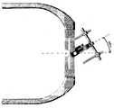
본 발명의 원리의 이해를 돕기 위한 목적으로, 도 1에 나타난 예시적이고, 비-제한적인 실시예를 참조할 것이다. 가운데 얼굴 확장기(10)는 머리얼굴 뼈의 일부 또는 일부들을 점진적으로 연장하기 위한 골형성 수술을 수행하기 위해 환자의 머리 및 가운데 얼굴의 뼈에 부착하는 외부 장치이다. 보이는 바와 같이, 가운데 얼굴 확장기(10)는 환자의 머리를 진입시키기 위한 외부 할로 어셈블리(20), 부착된 수직 중심 로드(150)를 포함하는 중심 조절 어셈블리(100), 적어도 하나의 확장 나사(270)를 포함하는 적어도 하나의 수평 크로스 피스 어셈블리(200), 및 확장될 타깃 머리얼굴 뼈에 마운팅된 적어도 하나의 발판 어셈블리(300)를 포함한다. 가운데 얼굴 확장기(10)는 또한 가운데 얼굴 확장기가 개인적인 외형 특성과 관련없이 대부분의 환자에 맞도록 하는 다양한 개별적 조절 장치를 포함할 수 있다.For purposes of understanding the principles of the present invention, reference will be made to the exemplary, non-limiting embodiment shown in FIG. 1. The middle face expander 10 is an external device that attaches to the patient's head and to the bones of the middle face to perform bone formation surgery to gradually extend some or some of the head facial bones. As can be seen, the middle face expander 10 includes an
가운데 얼굴 확장기(10)는 또한 종래에 이용가능한 장치보다 확장 벡터에 있어 더 크고 더 정확한 조절력을 외과의사에게 제공할 수 있는 다양한 개별적 조절 장치를 포함할 수 있다. 즉, 가운데 얼굴 확장기(10)는 외과의사에게 추가적인 전방-후방 및 중앙-측면 조절력을 제공하고, 이것에 의해 외과의사가 확장의 방향을 더 정밀하고 정확하게 조절할 수 있도록 한다. 게다가, 가운데 얼굴 확장기(10)는 또한 외과의사가 확장 수술이 개시된 후에 확장의 방향을 쉽고 정확하게 변경할 수 있도록 하며, 이것에 의해 외과의사에게, 필요한 경우, 수술 동안 어느 시기에라도 확장의 궁극 벡터를 재조절할 수 있게 한다.The middle face expander 10 may also include a variety of individual adjustment devices that can provide the surgeon with greater and more accurate control of the extension vector than previously available devices. That is, the middle face expander 10 provides the surgeon with additional anterior-rear and mid-lateral control, thereby allowing the surgeon to more precisely and accurately control the direction of the dilation. In addition, the mid-face expander 10 also allows the surgeon to easily and accurately change the direction of dilation after the dilatation surgery is initiated, thereby allowing the surgeon to recapture the ultimate vector of dilation at any time during the surgery, if necessary. To be adjustable.
할로 어셈블리(Halo assembly (HALOHaloASSEMBLYASSEMBLY))
할로 어셈블리는 확장 구성요소에 단단한 지지 구조를 제공하기 위하여 환자의 머리에 부착되는 구조적 프레임이다. 할로 어셈블리는 본 발명이 속한 분야에서 잘 알려져 있으며, 알려진 어떠한 할로 어셈블리가 본 발명과 조합하여 사용될 수 있다. 예를 들어, 할로 어셈블리는 어떠한 조절 장치 없이 환자의 머리를 에워싸고 부착하는 1개의 단일 피스일 수 있다.The halo assembly is a structural frame attached to the patient's head to provide a rigid support structure for the expansion component. Halo assemblies are well known in the art, and any known halo assembly can be used in combination with the present invention. For example, the halo assembly may be one single piece that encloses and attaches the patient's head without any adjustments.
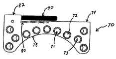
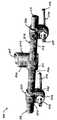
대안적으로, 도 2 및 3에 나타나는 바와 같이, 할로 어셈블리(20)는 두 개의 마운팅 플레이트(70)를 포함하는 U-형태 멤버일 수 있고, 마운팅 플레이트 각각은 복수 개의 머리 고정 구멍(71), 두 개의 측면 멤버(50), 및 두 개의 측면 멤버(50)를 상호연결하고 할로 어셈블리(20)와 중심 조정 어셈블리(100)를 연결하기 위한 중심 연결 허브(30)를 포함할 수 있다. 게다가, 할로 어셈블리(20)는 또한 할로 어셈블리가 개개 환자의 머리에 맞는 크기를 가지도록 조절하는 조절 장치를 포함할 수 있다. 즉, 할로 어셈블리(20)는 단독 또는 결합하여 할로 어셈블리의 총 너비 "W"를 조절하기 위한 중앙-측면 조절 장치, 및 할로 어셈블리(20)의 총 길이 "L"을 조절하기 위하여 각 측면 멤버(50) 내의 전방-후방 장치를 포함할 수 있다.Alternatively, as shown in FIGS. 2 and 3,
할로 어셈블리(20)의 측면 멤버(50)는, 위로부터 볼 때, 각각 일반적으로 "L" 형태 멤버일 수 있으며, 각 측면 멤버(50)는 환자의 머리의 각 측면을 감싸도록 설계된다. 측면 멤버(50)는 할로 어셈블리(20)에 유선형의 외관을 제공하는 반면, 동시에 가능한 가장 가벼운 구조를 제공하도록 설계될 수 있다. 도 4a-4d에 나타난 바와 같이, 각 측면 멤버(50)는 앞면 부분(52) 및 후면 부분(54)을 포함할 수 있고, 앞면 부분(52)은 환자에게 더 양호한 착용, 더 좋은 외관 및 더 편한 할로 어셈블리(20)를 제공하기 위하여 방사상(radius)일 수 있다. 앞면 부분(52)은 또한 연결 허브(30)의 한 측면과 맞물리도록 구성될 수 있으며(도 6a 내지 6c 참조), 반면에 후면 부분(54)은 마운팅 플레이트(70)와 맞물리도록 구성될 수 있다.The
도 5a 및 5b에 잘 나타나는 바와 같이, 마운팅 플레이트(70)는 본 발명이 속한 분야에서 알려진 어떠한 방법에 의해 할로 어셈블리(20)를 환자의 두개골에 고정하기 위하여 환자의 귀 위에 맞도록 설계될 수 있다. 따라서, 비록 마운팅 플레이트(70)는 어떠한 형태, 배열 또는 외형을 가질 수 있으나, 각 마운팅 플레이트(70)는 일반적으로 그의 바닥 표면(78)을 따라 형성된 아치형(arcuate) 도려낸 부분(cut-out)을 가진 직사각형의 플레이트이며, 이것은 환자의 귀 주위에 맞는 개선된 외형을 제공한다.As best seen in FIGS. 5A and 5B, the mounting
마운팅 플레이트(70)는 내부를 통해 연장하는 복수 개의 구멍(71)을 포함할 수 있어서, 상기 플레이트를 두개골에 고정하기 위하여 두개골의 관자놀이 및/또는 정수리 뼈 내, 환자의 귀 위 별개의 위치들에 두개골 고정 수단(미도시)이 삽입될 수 있다. 복수 개의 구멍(71)은 두개골 고정 수단을 수용하기에 적당한 어떠한 크기, 형태 또는 치수(dimension)일 수 있다. 구멍(71)은 또한 나사산을 가질 수 있어서, 할로 어셈블리(20)는 외부 나사산을 가진 두개골 고정 핀(미도시)에 의해 환자의 머리에 고정될 수 있다. 두개골 고정 핀들은 환자의 귀 위에 위치한 마운팅 플레이트(70)의 구멍(71)을 통하여 삽입될 수 있다. 나사산 두개골 고정 핀들과 함께 나사산 구멍(71)을 사용하여 환자의 두개 주위에 할로 어셈블리(20)를 위치시키기 전에 고정 핀들이 마운팅 플레이트(70) 내로 부분적으로 나사연결될(threaded) 수 있고, 이것에 의해 설치 절차를 간단화할 수 있다. 게다가, 고정 핀들은 피부를 관통하도록 배열된 미세하게 돌출된 말단을 가질 수 있고, 따라서 환자의 머릿가죽에 사전-절개를 할 필요가 없다. 대안적으로, 두개골 고정 수단은 자가-드릴 마운팅 핀들(미도시)을 포함할 수 있고, 이것은 뼈 나사산을 통하여 두개골과 적극적으로 결합된다. 게다가, 가운데 얼굴 확장기(10)는 위치 핀들(positional pins)(미도시)을 포함할 수 있고, 이것은 환자의 머릿가죽에 대한 할로 어셈블리(20)의 위치를 일시적으로 배치시킬 수 있는 크기와 배열을 가진다. 일단 바르게 위치되면, 위치 핀들은 제거되고, 영구적인 두개골 고정 수단으로 교체될 수 있다.The mounting
구멍(71)은 자신의 축이 마운팅 플레이트(70)의 평면에 수직인 형태로 지향될 수 있다. 대안적으로 구멍(71)은 마운팅 플레이트(70)의 평면에 대해 각을 이룰 수 있으며; 그러한 각도의 정도는 특정 환자 및/또는 수술에 적당할 수 있는데, 예를 들어 구멍은 마운팅 플레이트의 평면에 대하여 15도 각도를 가질 수 있다. 마운팅 플레이트(70)는 또한 곧은(72) 및 각진(73) 구멍들의 조합을 포함할 수 있으며, 곧은 구멍(72)은 일반적으로 플레이트(70)의 중간에 위치하고 각진 구멍(73)은 플레이트(70)의 외부 가장자리를 따라 위치한다. 그러나, 곧은(72) 및 각진(73) 구멍들의 어떠한 조합 및 배열들도 가능하다.The
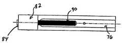
마운팅 플레이트(70)는 용접, 접착 등을 포함하는, 하지만 이에 한정되지 않는, 본 발명이 속한 분야에서 잘 알려진 어떠한 방법을 통하여 측면 멤버(50)에 연결될 수 있다. 대안적으로, 마운팅 플레이트(70)는 할로 어셈블리(20)의 측면 멤버(50)와 일체로 형성되거나 완전히 생략될 수 있는데, 대신 측면 멤버(50)는 두개골 고정 수단을 수용하기 위한 복수 개의 구멍(71)을 포함할 수 있다. 마운팅 플레이트(70)는 또한 측면 멤버(50)에 조정가능하도록 연결될 수 있으며, 그것에 의하여 할로 어셈블리(20)의 총 길이 "L"이 조정되도록 한다. 일 실시예에서, 측면 멤버(50)의 후면 부분(54)의 바닥 표면(56)은 마운팅 플레이트(70)의 정상 표면(74) 내 슬롯(76)과 맞물리기 위한 돌출부(58)를 포함할 수 있으며, 따라서 마운팅 플레이트(70)가 측면 멤버(50)를 따라 전방-후방 방향으로 미끄러지도록 한다. 돌출부(58)는, 예를 들어, 마운팅 플레이트(70)의 정상 표면(74) 내 대응하는 홈(groove)과 맞물리기 위한 도브테일(dovetail)일 수 있다. 게다가, 각 측면 멤버(50)의 후면 부분(54)은 또한 조절 나사(90)의 첫 번째 말단과 맞물리기 위한 내부 나사산을 가진 구멍(60)을 포함할 수 있다. 마운팅 플레이트(70)의 정상 표면(74)은 조절 나사(90)의 두 번째 말단을 회전가능하게 수용하기 위한 구멍(84)을 가진 위로 뻗은 부분(82)을 포함할 수 있다. 조절 나사(90)는 마운팅 플레이트 구멍(84) 내에 축 방향으로(axially) 유지될 수 있으므로, 상기 조절 나사(90)의 회전은 측면 멤버(50)가 조절 나사(90) 및 마운팅 플레이트(70) 둘 모두에 대하여 움직이도록 할 수 있다. 따라서 조절 나사(90)의 회전은 측면 멤버(50)가 마운팅 플레이트(70)를 따라 슬롯(76) 내에서 움직이도록 할 수 있다. 첫 번째 방향으로의 조절 나사(90)의 회전은 마운팅 플레이트(70)가 측면 멤버(50)에 가깝도록 측면 멤버(50)를 끌어당기도록 할 수 있고, 그것에 의해 할로 어셈블리(20)의 총 길이 "L"을 감소시킨다. 두 번째 방향으로의 조절 나사(90)의 회전은 마운팅 플레이트(70) 및 측면 멤버(50)가 서로 떨어지는 방향으로 움직이게 할 수 있고, 이것에 의하여 할로 어셈블리(20)의 총 길이 "L"을 증가시킨다. 보이는 바와 같이, 조절 나사(90)는 할로 어셈블리(20)의 길이 "L"을 확대되지 않은 길이를 넘어 최대 25 밀리미터(mm)까지 증대되도록 할 수 있다. 바람직하게, 도 5a에 나타난 바와 같이, 마운팅 플레이트(70)는 외과의사가 조절의 정도를 계산할 수 있도록 돕는 눈금(calibration), 예를 들어, 마킹(80)을 포함할 수 있다.The mounting
연결 허브(Connection hub (CONNECTIONCONNECTIONHUBHUB))
앞서 언급된 바와 같이, 각 측면 멤버(50)는 장착될 때 환자의 이마 중간에 가깝게 위치하는 앞면 부분(52)을 가질 수 있다. 연결 허브(30)는 각 측면 멤버(50)의 앞면 부분(52)을 서로서로 상호연결할 수 있으며, 반면에 또한 중심 조절 어셈블리(100)(뒤에 좀 더 자세히 설명됨)를 통해 할로 어셈블리(20)를 확장 장치의 나머지 부분(remainder)에 연결시키기 위한 장치를 제공할 수 있다. 도 4d에 일반적으로 보이는 바와 같이, 측면 멤버(50)의 높이 "h"는 후면 부분(54)으로부터 앞면 부분(52)까지 증가할 수 있으며, 따라서 측면 멤버(50)와 연결 허브(30)의 연결을 용이하게 하면서 무게를 최소화하고 할로의 총 외관을 유선형으로 할 수 있다.As mentioned above, each
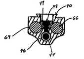
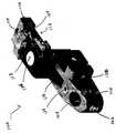
도 6a-6c에 보이는 바와 같이, 연결 허브(30)는 일반적으로 할로 어셈블리(20)의 총 너비 "W"를 조절하기 위하여 중심 피스(32) 및 측면 조절 장치(33)를 포함한다. 중심 피스(32)는 정사각형, 직사각형 등을 포함하는, 하지만 이에 한정되지 않는, 본 발명이 속한 분야에서 알려지니 어떠한 형태일 수도 있다. 예시적인 실시예에서, 중심 피스(32)는 정상 부분(34) 및 바닥 부분(36)을 가진 T-형태 윤곽을 가진다. 정상 부분(34)은 중심 조절 어셈블리(100)와 맞물리도록 구성되는 반면, 바닥 부분(36)은 측면 조절 장치(33)를 수용하도록 구성될 수 있다.As shown in FIGS. 6A-6C, the
중심 피스(32)의 바닥 부분(36)은 측면 조절 장치(33)와 맞물리기 위한 장치를 포함할 수 있다. 측면 조절 장치(33)는, 이에 한정되지 않지만, 래크(rack)와 피니언 톱니바퀴, 표준 나사, 나사산 기어 타입 장치 등을 포함하는 상호 연결된 멤버의 위치를 조절하기에 적당한, 본 발명이 속한 분야에서 알려진 어떠한 장치일 수 있다. 예시적인 실시예에서, 중심 피스(32)의 바닥 부분(36)은 프레임 조절 나사(44), 즉 측면 멤버(50)의 앞면 부분(52) 내에 형성된 대응 구멍(53)과 짝을 이루고 양쪽 말단의 양쪽 핸드(opposite hand)를 가진 나사들을 포함한 이중 나사산 나사를 수용하기 위한 수평 구멍(46)을 포함한다. 연결 허브(30) 내에 형성된 수평 구멍(46)은 또한 조절 나사(44)를 둘러싸고 그와 짝을 이루는 크기와 배열을 가진 베어링 멤버(46a)를 포함할 수 있다. 조절 나사(44)가 그 안에 위치된 후에 베어링 멤버(46a)는 수평 구멍(46) 내에 억지끼워 맞춰져 고정될 수 있으며 그것에 의하여 연결 허브(30)에 대한 조절 나사(44)의 축 위치를 고정한다. 보이는 바와 같이, 하나의 베어링 멤버(46a)는 조절 나사(44) 위에 형성된 홈(47)의 양 측면에 위치할 수 있다.The
게다가, 도 4c에 잘 나타나는 바와 같이, 측면 멤버(50) 내에 형성된 구멍(53)은 더 큰 직경을 가진 비-나사산 부분(53a)과 더 작은 직경을 가진 나사산 부분(53b)을 포함할 수 있다. 나사산 부분(53b)은 조절 나사(44)와 나사 결합되는 크기와 배열을 가질 수 있는 반면, 비-나사산 부분(53a)은 사용자가 원하는 방향으로 조절 나사(44)를 회전시킬 수 있도록 조절 나사(44)의 양 말단에 위치한 도구 결합 장치(45)와 맞물리기 위한 도구, 예를 들어, 나사 드라이버, 래치트 등을 수용하기 위한 크기와 배열을 가질 수 있다. 측면 멤버(50)에 조립될 때, 프레임 조절 나사(44)의 말단들은 각 측면 멤버(50)를 통해 뻗은 구멍(53)을 통하여 접근가능할 수 있다.In addition, as well shown in FIG. 4C, the
그 후, 첫 번째 방향으로의 프레임 조절 나사(44)의 회전은 할로 어셈블리(20)의 측면 멤버(50)가 연결 허브(30) 쪽으로 끌리도록 하며, 그것에 의하여 할로 어셈블리(20)의 총 너비 "W"를 감소시킨다. 유사하게, 프레임 조절 나사(44)의 두 번째 방향으로의 회전은 측면 멤버(50)가 연결 허브(30)로부터 멀어지도록 야기하며, 그것에 의하여 할로의 총 너비 "W"를 증가시킨다. 프레임 조절 나사(44)는 연결 허브(30)의 각 측면 위에서 약 0 mm에서부터 약 40 mm까지의 조절이 가능할 수 있다.Thereafter, the rotation of the
각 측면 멤버(50)의 서로에 대한 꼬임과 연결 허브(30)에 대한 꼬임을 방지하고, 할로(20)의 원활한 측면 조절을 가능하게 하기 위하여, 측면 조절 장치(33)는 또한 조절 나사(44)의 양 측면에 그와 평행하게 위치한 적어도 하나, 바람직하게는 두 개의 강화 로드(reinforcing rod)(66)를 포함할 수 있다(도 2에 도시됨). 그러나, 강지그화 로드(66)의 개수와 배열이 제한되는 것은 아니다. 각 로드(66)는 각각 측면 멤버(50) 및 연결 허브(30) 내에 형성된 대응 오목부위(recess)(68, 69)에 맞도록 설계되고 배열될 수 있어서 로드들(66)은 일반적으로 오목부위들(68, 69) 내로 미끄러질 수 있다. 따라서, 조절 나사(44)가 회전할 때, 부드러운 움직임을 위해 측면 멤버(50)는 로드들(66)을 따라 미끄러지고, 그 위로 가이드된다.In order to prevent the twisting of each
연결 허브(30) 및 측면 멤버(50)는 또한 일단 너비가 결정된다면 할로 어셈블리(20)의 총 너비 "w"를 고정하기 위한 잠금 장치(31)를 포함할 수 있다. 비록 어떠한 수의 잠금 장치(31)도 사용될 수 있지만, 도 3에 잘 나타나는 바와 같이, 바람직하게는 확장기(10)는 세 개의 잠금 장치(31)를 포함하는데, 측면 멤버(50)에 각각 하나씩과 연결 허브(30)에 하나를 포함한다. 잠금 장치(31)로는 표준 세트 나사를 포함하는, 하지만 이에 한정되지 않은, 움직일 수 있는 멤버의 상대적 위치를 고정하기에 적당한 본 발명이 속한 분야에서 알려진 어떠한 장치도 사용될 수 있다. 그러나, 도 6c에 잘 나타나는 바와 같이, 잠금 장치(31)는 나사(48) 및 로드 자물쇠(rod lock)(49)를 포함할 수 있다. 상기 나사(48) 및 로드 자물쇠(49)는 허브(30) 내 구멍을 통해 연장하는 크기와 배열을 가질 수 있어서 로드 자물쇠(49)는 강화 로드(66)의 외부 영역(circumference)과 접촉한다. 상기 나사(48)는 로드 자물쇠(49)를 통해 조절 나사(44) 내에 형성된 홈(47) 안으로 연장하는 크기와 배열을 가질 수 있다. 그 후, 상기 나사(48)의 회전은 로드 자물쇠(49)가 강화 로드(66)를 내리누르도록 하며, 따라서 연결 허브(30)에 대하여 강화 로드(66)의 위치를 고정한다. 비록 잠금 장치(31)가 연결 허브(30)와 관련지어 설명되었지만, 앞서 언급된 바와 같이, 각 측면 멤버(50)가 위에서 설명된 것과 동일한 잠금 장치(31)를 포함할 수 있다.The
연결 허브(30)의 정상 부분(34)은 연결 허브(30)를 중심 조절 어셈블리(100)에 연결하기 위한 부착 장치를 포함할 수 있다. 부착 장치는 나사, 용접 등을 포함하는, 하지만 이에 한정되지 않는, 본 발명이 속한 분야에서 알려진 어떠한 수단일 수 있다. 예시적인 실시예에서, 중심 피스(32)의 정상 부분(34)의 상부 표면(38)은 중심 조절 어셈블리(100) 내에 위치한 대응 슬롯(112)과 맞물리기 위한 프레임 조절 나사(44)의 축(즉, 장치가 환자 위에 마운팅될 때, 중앙-측면 축)에 일반적으로 평행한 위치를 가진 돌출부(40)를 가질 수 있다. 상기 돌출부(40)는 중심 조절 어셈블리(100) 내에 위치한 대응 홈과 맞물리기 위한 도브테일일 수 있으며, 따라서 외과의사는 중심 조절 어셈블리(100)를 연결 허브(30)의 중앙-측면 축을 따라 미끄러지게 할 수 있다. 따라서, 외과의사는 환자의 시야를 방해하는 것을 최소화하기 위하여 환자의 얼굴 앞의 바람직한 위치로 수직 중심 로드(150)(후술함)의 측면 위치를 조절하도록 이러한 부착 장치를 사용할 수 있다. 연결 허브(30)의 정상 부분(34)은 두 개의 중심 조절 어셈블리(100)를 동시에 수용하고 그와 맞물릴 수 있는 크기와 배열을 가져서, 만약 외과의사가 원한다면, 두 개의 중심 조절 장치(100) 및 두 개의 대응 수직 중심 로드(150)를 장착할 수 있다. 따라서, 이것은 외과의사에게 확장 벡터에 대한 더 크고 더 정확한 조절력을 제공할 수 있는 추가적인 조절력을 제공한다. 그것은 또한 외과의사가 수직 중심 로드(150)를 환자의 중심 시야에서 환자의 시야의 바깥으로 멀리 이동시킬 수 있도록 하여, 환자의 시야에 간섭하는 정도를 최소화할 수 있다.The
연결 허브(30)는 중심 조절 장치(100)의 세트 나사(114)를 수용할 수 있는 홈(미도시)을 추가로 포함할 수 있어서, 중심 조절 장치(100) 및 대응 수직 중심 로드(150)가 바르게 위치할 때, 세트 나사(114)의 회전으로 연결 허브(30)에 대한 중심 조절 장치(100)의 측면 위치가 고정된다. 바람직하게, 세트 나사(114) 및 홈은 중심 조절 어셈블리(100)가 연결 허브(30)에 대해 움직일 수 있도록 세트 나사(114)가 느슨한 정도의 크기와 배열을 가진다. 그러나, 느슨한 상태에서도, 세트 나사(114) 및 홈은 세트 나사(114)가 홈으로부터 제거될 수 없을 정도의 크기와 배열을 가져서, 연결 허브(30)와 중심 조절 장치(100)가 분리되는 것을 막는다.The
측면 멤버(50), 연결 허브(30) 및 강화 로드(66)는 본 발명이 속한 분야에서 알려진 물질, 예를 들어, 티타늄, 알루미늄, 스테인리스 스틸, 고분자, 카본 섬유 등과 같은, 하지만 이에 한정되지 않는, 물질들로부터 제조될 수 있다. 바람직하게, 연결 허브(30)는 양극 처리된 티타늄이며, 그것은 연결 허브(30) 및 중심 조절 장치(100) 사이에서 미끄러지는 움직임을 용이하게 하는 윤활성을 제공한다.
중심 조절 어셈블리Centering assembly
도 1에 잘 나타나는 바와 같이, 중심 조절 어셈블리(100)는 할로 어셈블리(20)를 수직 중심 로드(150)에 연결하고, 따라서 수직 중심 로드(150) 및 그에 결합된 수평 로드들, 클램프들 및 확장 나사들을 환자의 얼굴 앞 바람직한 위치에서 지탱한다. 할로 어셈블리(20)를 수직 중심 로드(150)와 연결하는 장치로는 예를 들어, 하지만 이에 한정되지 않는, 도 10에 나타난 한 개의 단일 피스가 사용될 수 있다. 바람직하게, 그러나, 도 7에 잘 나타나는 바와 같이, 중심 조절 어셈블리(100)는 할로 어셈블리(20)에 대해 수직 중심 로드(150)를 조절하기 위한 다양한 개별 조절 장치들을 포함할 수 있다. 즉, 중심 조절 어셈블리(100)는 단독으로 또는 결합하여 상부-하부 축에 대하여, 중앙-측면 축에 대하여 수직 중심 로드(150)의 회전을 가능하게 하고, 또한 수직 중심 로드(150)의 중앙-측면 및 수직 조절을 가능하게 한다.As best seen in FIG. 1, the
도 7에 나타나는 바와 같이, 중심 조절 어셈블리(100)는 앞면 부분(102) 및 후면 부분(110)을 포함할 수 있다. 중심 조절 어셈블리(100)의 후면 부분(110)은 연결 허브(30)의 부착 수단과 짝을 이룬다. 즉, 앞서 설명한 바와 같이, 중심 조절 어셈블리(100)의 후면 부분(110)은 연결 허브(30)의 정상 부분(34)의 상부 표면(38) 위에 위치한 대응 돌출부(40)와 맞물리기 위한 슬롯(112)을 포함할 수 있다. 상기 돌출부는 중심 조절 어셈블리(100)에 위치한 대응 홈과 맞물리는 도브테일(dovetail)일 수 있다. 이것은 외과의사가 중심 조절 어셈블리(100)를 연결 허브(30)의 중앙-측면 축을 따라 미끄러지게 할 수 있도록 한다. 따라서, 외과의사는 환자의 시야를 가리는 것을 최소화하기 위하여 환자의 얼굴 앞의 바람직한 위치로 수직 로드(150)의 측면 위치를 조절할 수 있다. 앞서 언급된 바와 같이, 수직 로드(150)의 중앙-측면 및 수직 위치가 외과의사에 의해 선택된 후에, 후면 부분(110)은 또한 연결 허브(30)에 대한 중심 조절 어셈블리(100)의 측면 위치를 고정하기 위한 세트 나사(114)를 포함할 수 있다.As shown in FIG. 7, the
중심 조절 어셈블리(100)의 앞면 부분(102)은 할로 어셈블리(20)로부터 전방을 향하여 외측으로 연장할 수 있고, 수직 중심 로드(150)의 상부 부분과 구멍(104)을 통해 짝을 이룰 수 있으며, 수직 중심 로드는 하부 부분에서 수평 크로스-피스 어셈블리(200)와 연결되어 있다(뒤에서 자세히 설명될 것임). 구멍(104)은 일반적으로 중심 조절 어셈블리(100)의 정상 표면에 실질적으로 수직인 방향으로 배열된 축을 가질 수 있다. 구멍(104)은 비-원형 또는 쐐기가 있는(keyed) 수직 중심 로드와 짝을 이루기 위하여 비-원형 또는 쐐기가 있는 단면을 가질 수 있다. 그러나, 바람직하게는, 상기 로드(150)는 외부 표면을 따라 세로로 뻗어 있는 슬롯(미도시)을 가지며, 상기 슬롯은 중심 조절 어셈블리(100)의 세트 나사(106)와 짝을 이루며 그와 맞물리는 크기와 배열을 가진다. 세트 나사(106)와 슬롯의 짝짓기는 수직 중심 로드(150)가 중심 조절 어셈블리(100)에 대하여 회전하는 것을 막는다. 게다가, 세트 나사(106)의 회전은 또한 수직 중심 로드(150)가 외과의사에 의해 바람직한 위치로 설정된 후에 중심 조절 어셈블리(100)에 대한 로드(150)의 축 위치를 확고히 할 수 있다.The
앞서 설명된 바와 같이, 중심 조절 어셈블리(100)는 또한 할로 어셈블리(20)에 대한 수직 중심 로드(150)의 추가적인 조절을 가능하게 하는 다양한 조절 장치를 단독으로 또는 조합하여 포함할 수 있다. 즉, 중심 조절 어셈블리(100)는 중앙-측면 축 및 상부-하부 축을 중심으로 수직 중심 로드(150)의 각도 조절을 가능하게 하는 배열을 가질 수 있다(따라서 그것에 부착될 수 있는 수평 크로스-피스 어셈블리(200)의 매우 다양한 각도 조절이 가능하다). 이러한 각도 조절은 래크와 피니언, 구형 조인트, 미늘톱니바퀴장치 및 톱니 타입 어셈블리, 캠 및 수행물(follower) 타입 어셈블리 등과 같은, 하지만 이에 한정되지 않는, 본 발명이 속한 분야에서 알려진 어떠한 장치에 의해서 제공될 수 있다. 대안적으로, 도 10에 나타나는 바와 같이, 중심 조절 어셈블리(100)는 수직 중심 로드(150)에 할로 어셈블리(20)를 연결하는 비-조정 단일 피스로 제공될 수 있다. 그러나, 바람직하게는, 도 7에 나타나는 바와 같이, 중심 조절 어셈블리(100)는 할로 어셈블리(20)에 대한 수직 중심 로드(150)의 조절을 가능하게 하는 다양한 개별 조절 장치를 포함한다. 보이는 바와 같이, 중심 조절 어셈블리(100)는 중심 조절 어셈블리(100)의 앞면 부분(102)과 후면 부분(110) 사이에 위치한 적어도 하나의 웜(worm)-기어 장치를 포함할 수 있다. 보이는 바와 같이, 비록 웜 기어 장치의 수는 제한되지 않지만, 중심 조절 어셈블리(100)는 두 개의 웜-기어 장치(116, 118)를 포함할 수 있다. 웜 기어 장치(116, 118)는 웜 나사(122, 124)를 가질 수 있으며, 이들은 중심 조절 어셈블리(100)의 정상 표면 또는 측면에 위치할 수 있다. 웜 기어 장치(116, 118)의 이용은 외과의사가 웜 나사(122, 124)의 각각의 회전으로 웜 기어 및 수직 로드(150)를 불연속의 정확한 양만큼 회전시키는 것을 가능하게 하고, 이것에 의하여 확장 벡터의 조절에 대한 보다 정확한 조절력을 제공할 수 있다. 웜 나사 및 웜 기어 나사산의 피치는 나사(122, 124)의 회전의 정도에 대한 기어의 원하는 움직임 양을 제공하도록 선택될 수 있으며; 이것은 설계 선택의 문제이다.As described above, the
보이는 바와 같이, 첫 번째 웜 기어(116)는 수직 중심 로드(150)의 상부-하부 회전(즉, 중앙-측면 축에 대한 회전)을 가능하게 하고, 두 번째 웜 기어(118)는 수직 중심 로드(150)의 중앙-측면 회전(즉, 상부-하부 축에 대한 회전, 즉, 착용자의 몸체를 통해 수평으로 통과하는 평면에 수직인 축)을 가능하게 한다. 중심 조절 어셈블리(100)의 웜 기어 장치(116, 118)는, 비록 다른 회전 범위가 가능하지만, 도 8에 나타나는 바와 같이, 중앙-측면 회전 약 +/- 30 도 및 상부-하부 회전 +45 내지 -30 도를 가능하게 한다.As can be seen, the
각 웜 기어 장치(116, 118)는 또한 세트 나사(120, 126)를 포함할 수 있다. 일단 조여지면, 세트 나사(120, 126)는 중심 조절 어셈블리(100)의 추가적인 움직임을 억제한다.Each
수직 중심 로드Vertical center rod
도 1에 나타나는 바와 같이, 수직 중심 로드(150)는 첫 번째 말단(152) 및 두 번째 말단(154)을 가진 로드일 수 있다. 첫 번째 말단(152)은 중심 조절 어셈블리(100)의 구멍(104)과 미끄러져 맞물리고, 두 번째 말단(154)은 수평 크로스-피스 어셈블리의 중심 클램프(202)와 미끄러져 맞물린다(후에 좀 더 자세히 설명됨). 수직 중심 로드(150)는 수평 크로스-피스 어셈블리(200) 및 중심 조절 어셈블리(100)가 길이를 따라 실질적으로 어느 곳에나 위치할 수 있도록 하며, 따라서 수평 크로스-피스 어셈블리(200), 확장 나사(270) 및 뼈-결합 부분(302)의 위치를 결정하는데 최대한의 자유를 제공할 수 있다. 일단 수직 중심 로드(150)가 바르게 위치되면, 중심 조절 어셈블리(100)와 중심 클램프(202) 각각의 세트 나사(106, 206)는 단단히 조여져 수직 중심 로드(150)의 추가적인 움직임을 제한한다.As shown in FIG. 1, the
앞서 언급된 바와 같이, 수직 중심 로드(150)는 바람직하게는 외부 표면을 따라 뻗은 세로 슬롯을 가지며, 상기 슬롯은 후에 좀 더 자세히 설명되는 바와 같이 중심 조절 어셈블리(100)의 세트 나사(106) 및 중심 클램프(202)의 세트 나사(206)와 짝을 이루는 배열과 크기를 가져서 중심 조절 어셈블리(100) 및 중심 클램프(202)에 대한 수직 중심 로드(150)의 회전을 방지한다.As mentioned above, the
수직 중심 로드(150)는 알루미늄, 티타늄, 니티놀(nitinol), 고분자, 카본 섬유 물질 등을 포함하는, 하지만 이에 한정되지 않는, 본 발명이 속한 분야에서 알려진 어떠한 물질로도 만들어질 수 있다.The
수평level크로스cross--피스peace 어셈블리 assembly
수평 크로스-피스 어셈블리(200)는 발판 어셈블리(300)와 연결되는 수직 중심 로드(150)를 확장 나사(270)에 연결한다. 도 1에 나타나는 바와 같이, 가운데 얼굴 확장기(10)는 두 개의 수평 크로스-피스 어셈블리(200)를 포함할 수 있는데, 하나는 턱 뼈의 확장을 제공하고 다른 하나는 광대 뼈의 확장을 제공한다. 그러나, 수평 크로스-피스 어셈블리(200)의 수가 제한되는 것은 아니다. 예를 들어, Lefort I 외과 수술에 있어, 일반적으로 단지 하나의 수평 크로스-피스 어셈블리(200)가 턱 뼈를 확장하기 위하여 요구된다.The
수평 크로스-피스 어셈블리(200)는 확장 벡터의 추가적인 조절을 위한 장치를 제공할 수 있다. 수평 크로스-피스 어셈블리(200)는 확장 나사(270)의 위치에 대한 측면 조절, 가로축(transverse) 회전, 및 상부-하부 방향 조절을 위한 장치를 포함할 수 있다.The
도 11 및 12에 잘 나타나는 바와 같이, 수평 크로스-피스 어셈블리(200)는 중심 클램프(202), 수평 로드(212) 및 두 개의 확장기 클램프(230)를 포함한다. 중심 클램프(202)는 수직 중심 로드(150)를 수평 로드(212)에 연결한다. 도 13a 및 13b에 나타나는 바와 같이, 중심 클램프(202)는 내부를 통해 연장하는 두 개의 비-교차(non- intersecting) 구멍들- 수직 구멍(204) 및 수평 구멍(208)-을 가진 블록(block) 멤버이다. 수직 구멍(204)은 일반적으로 상부-하부 축을 따라서 중심 클램프(202)를 통하여 뻗어 있으며, 수평 구멍(208)은 일반적으로 중앙-측면 축을 따라서 중심 클램프(202)를 통하여 뻗어 있다. 앞서 언급된 바와 같이, 중심 클램프(202)는 수직 중심 로드에 형성된 슬롯과 맞물리기 위한 세트 나사(206)를 포함하며, 이것에 의하여 수직 로드(150) 및 중심 클램프(202) 사이의 회전을 방지한다. 일단 단단히 조여지면, 세트 나사(206)는 수직 중심 로드(150)에 대한 중심 클램프(202)의 움직임을 방지한다. 수평 구멍(208)은 원형 수평 로드(212)와 짝을 이루기 위하여 원형일 수 있으며, 이것에 의하여 중심 클램프(202)에 대한 수평 로드(212)의 회전을 허용한다. 중심 클램프(202)는 또한 수평 로드(212)와 맞물리기 위한 세트 나사(210)를 포함할 수 있다. 일단 단단히 조여지면, 세트 나사(210)는 수평 로드(212)에 대한 중심 클램프(202)의 움직임을 방지한다.As best seen in FIGS. 11 and 12, the
수평 로드(212)는 일반적으로 수직 중심 로드(150)의 세로 축에 수직인 축을 따라 배열된다. 수평 로드(212)는 중심 클램프(202)와 확장기 클램프(230)를 상호연결하며, 확장기 클램프(230)는, 도시된 바와 같이, 중심 클램프(202)의 양 측면에 위치할 수 있다. 그러나, 확장기 클램프(230)의 수와 배열이 제한되는 것은 아니다. 수평 로드(212)는 첫 번째 말단(214), 두 번째 말단(216) 및 그들 사이에 위치한 중심 부분(218)을 가진다. 첫 번째 및 두 번째 말단(214, 216) 각각은 각각의 대응 확장기 클램프(230)의 구멍(232)과 미끄러져 맞물릴 수 있으며, 수평 로드(212)의 중심 부분(218)은 중심 클램프의 수평 구멍(208)과 미끄러져 맞물릴 수 있다. 수평 로드(212)의 중심 부분(218)은 중심 클램프(202)의 수평 세트 나사(210)를 수용하고 그와 맞물리기 위한 길이의 적어도 일부분을 따라 홈(220)을 가질 수 있다. 수평 로드(212)가 중심 클램프(202)에 대해 회전하는 것을 방지하기 위해, 홈(220)은 세트 나사(210)와 상호작용할 수 있다.
보이는 바와 같이, 확장기 클램프(230)는 수평 로드(212)를 수용하기 위한 수평 구멍(232) 및 확장 나사(270)를 수용하기 위한 확장 나사 구멍(236)을 가진 블록 멤버를 포함할 수 있다. 수평 구멍(232)은 수평 로드(212)의 원형 횡단과 짝을 이루는 원형일 수 있다. 이러한 형태는 확장기 클램프(230)가 수평 로드(212)의 길이를 따라 실질적으로 어느 곳에서나 위치할 수 있도록 하며, 따라서 외과의사가 확장 나사(270) 및 그것에 부착한 발판(300)의 측면 위치를 조절하는 것을 가능하게 한다. 게다가, 원형 수평 구멍(232)은 외과의사가 확장기 클램프(230) 및 확장 나사(270)를 수평 로드(212)의 축에 대하여 회전할 수 있도록 하고, 따라서 외과의사가 수평 로드(212)에 대하여 확장 나사(270)의 각을 다양하게 할 수 있도록 하며, 이것에 의하여 확장의 방향 및 각도, 특히 상부-하부 방향에 대한 추가적인 조절력을 제공한다. 각 확장기 클램프(230)는 또한 세트 나사(234)를 포함할 수 있고, 이것이 단단히 조여질 때 수평 로드(212)에 대한 확장기 클램프(230)의 움직임 및 회전이 억제된다.As shown, the
확장 나사 구멍(236)은 일반적으로 수평 로드(212)의 축에 수직인 배열의 축을 가진다. 확장 나사 구멍(236)은 확장 나사(270), 및 확장 나사(270)와 나사 결합하기 위한 확장 너트(238), 예를 들어, 6각 너트 등을 수용하도록 구성될 수 있다. 따라서, 확장 너트(238)의 회전으로 확장 나사(270)는 확장 구멍(236)을 통해 끌어당겨져 부착된 뼈 조각을 확장할 수 있다(후에 좀 더 자세히 기술됨).
도 12, 14a, 14b, 15a-15c, 16a, 및 16b를 참조하며, 각 확장기 클램프(1230)는 또한 회전 구성(swivel feature)을 포함할 수 있다. 회전형 확장기 클램프(1230)는 다중 피스들로 이루어질 수 있고, 각각은 결합된 피스에 대해 회전 할 수 있다. 보이는 바와 같이, 회전형 확장기 클램프(1230)는 정상 피스(1240) 및 바닥 피스(1250)를 포함할 수 있으며, 정상 피스(1240)는 수평 로드(1212)와 결합되고, 바닥 피스(1250)는 확장 나사(270)와 결합된다. 즉, 도 14a, 14b, 15a-15c, 16a, 및 16b에 잘 나타나는 바와 같이, 회전형 확장기 클램프(1230)의 정상 피스(1240)는 수평 로드(1212)와 미끄러져 맞물리기 위한 수평 구멍(1232)을 가질 수 있고, 바닥 피스(1250)는 확장 나사(270)와 맞물리기 위한 확장 나사 구멍(1236)을 가질 수 있다. 정상 및 바닥 피스(1240, 1250)는 바닥 피스(1250)와 그에 부착되는 확장 나사(270)가 정상 피스(1240)와 그에 결합되는 수평 로드(212)에 대하여 회전하도록 본 발명이 속한 분야에서 알려진 적당한 방법으로 연결될 수 있다. 바닥 피스(1250)는 일반적으로 수직 중심 로드(150)의 축과 평행하고 그로부터 오프셋된 축을 중심으로 회전할 수 있다. 그러나, 회전 축은 설계 선택의 문제이며, 다른 회전 축이 제공될 수도 있다. 회전형 확장기 클램프(1230)의 사용은 외과의사에게 확장 나사(270)의 위치를 고정하는 데 있어서 확장의 궁극적 방향에 대한 또 다른 조절 선택권을 부여한다. 바람직하게, 회전형 확장기 클램프(1230)는 +/- 20 도의 회전을 허용할 수 있다.12, 14A, 14B, 15A-15C, 16A, and 16B, each
정상 피스(1240)는 하부 피스(1250)의 정상 표면(1252)으로부터 뻗어 있는 수직 포스트(1254)를 수용하기 위해 정상 피스(1240)의 바닥 표면(1242)으로부터 뻗은 수직 구멍(1244)을 포함할 수 있고, 수직 포스트(1254) 및 수직 구멍(1244)은 짝을 이루는 횡단면을 가지며, 따라서 바닥 피스(1250)가 정상 피스(1240)에 대하여 회전 또는 선회하여 확장 나사(270)의 가로 회전(transverse rotation)이 가능해진다. 정상 피스(1240)는 또한 수직 포스트(1254) 내의 홈(1256)과 짝을 이루는 팁을 갖는 세트 나사(1246)를 포함할 수 있으며, 이것이 단단히 조여질 때 정상 피스(1240) 및 바닥 피스(1250) 사이의 추가적인 회전 또는 선회가 억제되며, 이것에 의하여 확장 나사(270)가 추가적인 회전을 하는 것을 막는다. 정상 피스(1240)의 바닥 표면(1242) 및 바닥 피스(1250)의 정상 표면(1252)은 또한 상호교합 치부(interlocking teeth)(1258)를 포함할 수 있어서 정상 부분(1240)에 대하여 바닥 부분(1250)이 일시적으로 잠겨지게(lock), 즉, 고정된다.The
게다가, 바람직하게, 정상 피스(1240) 및 수직 포스트(1254) 내에 형성된 홈(1256)은 도 14b에 잘 나타나는 바와 같이 핀(1270)을 수용하기 위한 배열 및 크기를 가질 수 있다. 세트 나사(1246)가 느슨해질 때, 확장기 클램프(1230)의 정상 및 바닥 피스들(1240, 1250)이 분리되는 것을 막기 위하여, 핀(1270)은 정상 피스(1240) 내에 형성된 수직 구멍(1244) 및 수직 포스트(1254)와 짝을 이루는 크기와 배열을 갖는다.In addition, the
대안적으로, 회전형 확장기 클램프(1230)의 정상 및 바닥 피스들(1240, 1250)은 거꾸로 반대일 수 있다. 즉, 회전형 확장기 클램프(1230)의 정상 피스(1240)가 확장 나사(270)와 맞물리기 위한 확장 나사 구멍(1236)을 포함하는 반면, 바닥 피스(1250)가 수평 로드(1212)와 미끄러져 맞물리기 위한 수평 구멍(1232)을 가질 수 있다.Alternatively, the top and
확장 나사(270)는 일반적으로 수직 중심 로드(150) 및 수평 로드(212) 모두에 수직인 배열을 가지나, 회전형 확장기 클램프(1230)는 수평 로드(1212)의 축에 대한 이러한 배열의 조절을 가능하게 한다. 확장 나사(270)는 환자의 얼굴을 향해 내부로 뻗은 원위 말단(272) 및 위에서 설명된 바와 같이 확장기 클램프(230)와 맞물리는 근위 말단(274)을 포함할 수 있다. 바람직하게는, 확장 나사(270)는 원위 말단(272)으로부터 근위 말단으로 뻗은 마킹과 같은 에칭된 눈금을 가져서 외과의사가 수행된 확장의 정확한 양을 측정하는 것을 도와준다. 각 확장 나사(270)의 원위 말단(272)은 내부를 관통하도록 드릴이나 다른 방식으로 형성된 구멍(276)을 포함할 수 있다. 상기 구멍(276)은 일반적으로 와이어(285)를 수용할 수 있는 배열을 가지며, 와이어는 확장 나사(270)와 대응 발판 어셈블리(300)를 연결하기 위하여 사용된다. 확장 나사(270)와 뼈-결합 부분(302)을 연결하기 위한 와이어(285)의 사용은 (뒤에 좀 더 자세히 기술됨) 가운데 얼굴 확장기(10)가 쉽게 분리되도록 하고 뼈-결합 부분(302)을 제거하기 위한 두 번째 절개의 필요성을 없앨 수 있다. 즉, 뼈-결합 부분(302)은 낮은 프로파일을 갖도록 제조될 수 있어서, 원할 경우, 환자의 턱 뼈 및 광대 뼈에 표시없이, 표시가 있더라도 육안으로 거의 관찰할 수 없을 정도로 부착된 채 남겨질 수 있으므로, 뼈-결합 부분(302)을 제거하기 위한 두 번째 절개 필요성을 제거한다. 게다가, 뼈-결합 부분(302)은 생체 재흡수성(bioresorbable) 물질로 제조될 수 있기 때문에 수술 후에도 환자에 남겨질 수 있다. 생체 재흡수성 발판은 시간이 지남에 따라 자연히 없어지고, 따라서 그들의 제거를 위한 필요성이 없앤다. 와이어(285)의 사용은 뼈-결합 부분(302)을 확장 나사(270)로부터 쉽게 분리되도록 하고, 이것에 의해 가운데 얼굴 확장기(10)가 환자의 머리로부터 쉽게 분리되어 제거되도록 한다. 와이어(285)는 24 또는 26 게이지 스테인리스 스틸 와이어를 포함하는, 하지만 이에 한정되지 않는, 본 발명이 속한 분야에서 알려진 적당한 물질로 제조될 수 있다. 그러나, 와이어(285)의 사용은 결정적인 부분은 아니며, 대안적으로 확장 나사(270)는 뼈-결합 부분(302)과 직접 맞물릴 수 있다.The
발판 어셈블리(Scaffolding assembly (FOOTPLATEFOOTPLATEASSEMBLYASSEMBLY))
발판 어셈블리(300)는 확장 나사(270)를 확장될 타깃 뼈 조각에 연결한다. 도 1에 나타나는 바와 같이, 가운데 얼굴 확장기(10)는 네 개의 발판 어셈블리(300)를 가질 수 있다. 그러나, 앞서 언급된 바와 같이, 그 수는 결정적인 것은 아니며, 어떠한 갯수의 발판 어셈블리(300)도 사용될 수 있다. 가운데 얼굴 확장기(10)는 타깃 뼈 조각을 각각의 확장 나사(270)와 연결하는 턱 뼈 및 광대 뼈 발판 어셈블리들을 포함할 수 있다. 턱 뼈 및 광대 뼈 발판 어셈블리들은 일반적으로 가운데 얼굴 확장기(10)가 타깃 뼈 조각에 쉽게 부착되고 타깃 뼈 조각으로부터 쉽게 제거될 수 있는, 즉 환자의 편안함을 최대로 할 수 있는 배열을 가진다.
턱 뼈 발판 어셈블리(310)는 일반적으로 턱 뼈 조각, 일반적으로 치아 버드(bud) 바로 위 턱 뼈 조각을 수평 크로스-피스 어셈블리(200)에 연결한다. 하나 이상의 크로스-피스 어셈블리(200)가 사용될 때, 턱 뼈 발판 어셈블리(310)는 일반적으로 낮은 수평 크로스-피스 어셈블리(200)에 연결된다. 광대 뼈 발판 어셈블리(340)는 광대 뼈 조각을 상부 크로스-피스 어셈블리(200)에 연결한다(하나 이상의 수평 크로스-피스 어셈블리가 사용될 때).Jaw
발판 어셈블리(300)는 일반적으로 턱 뼈 또는 광대 뼈와 직접 결합하기 위한 뼈-결합 부분(302)을 포함한다. 뼈-결합 부분(302)은 발판일 수 있고, 외과의사가 원하고, 특정 뼈에 허용되거나 및/또는 수술이 필요한 광대 뼈, 턱 뼈, 코, 눈확아래 언저리(infraorbital rim), 또는 조롱박(pyriform) 아퍼라춰(aperature)에 연결하기 적당한 다양한 형태로 제공될 수 있다. 뼈-결합 부분(302)은 뼈에 고정하기 위한 뼈 결합 나사(미도시)를 수용하기 위해 내부를 관통하는 하나 이상의 구멍(304)을 가질 수 있고, 구멍(304)의 수는 설계 선택의 문제이다. 뼈-결합 부분(302)은 티타늄, 생체 재흡수성 물질 등을 포함하는, 하지만 이에 한정되지 않는, 본 발명이 속한 분야에서 알려진 어떠한 적당한 물질로 제조될 수 있다. 대안적으로, 턱 뼈 발판 어셈블리(310)의 뼈-결합 부분(302)은 단단한 구강-내 스프린트(sprint)일 수 있으며, 구강 스프린트는 환자의 치아와 가운데 얼굴 확장기(10)의 결합을 가능하게 하고, 따라서 턱 뼈 내에 뼈 나사를 설치해야 하는 필요성이 없다. 본 발명이 속한 분야에서 알려진 어떠한 구강 내 스프린트도 사용될 수 있다. 일 실시예에서, 구강-내 스프린트는 환자의 나이에 따라 일차 또는 이차 큰어금니에 맞는 치아교정 밴드를 포함할 수 있다. 치아교정 밴드는 턱 뼈와 결합된 치아의, 전부는 아니더라도, 대부분과 밀접하게 접촉하도록 구부러질 수 있다. 구강-내 스프린트는 연결 와이어를 추가로 포함할 수 있고, 이것은 치아교정 밴드로부터 돌출한다. 연결 와이어는 와이어(285)를 통해 또는 직접적으로 확장 나사(270)와의 연결을 용이하게 한다. 치아교정 밴드 및 연결 와이어는 스테인리스 스틸 와이어, 예를 들어, 0.045 또는 0.050 스테인리스 스틸 와이어를 포함하는, 하지만 이에 한정되지 않는, 본 발명이 속한 분야에서 알려진 적당한 물질로 제조될 수 있다.
도 17에 나타나는 바와 같이, 턱 뼈 발판 어셈블리(310)는 또한 확장기-결합 부분(320), 확장기 로드(312) 및 (위에서 설명된 것과 같은) 뼈-결합 부분(302)을 포함할 수 있다. 확장기 로드(312)는 일반적으로 뼈-결합 부분(302)을 확장기-결합 부분(320)과 연결하기 위하여 사용되며, 첫 번째 말단(314) 및 두 번째 말단(316)을 가진다. 확장기 로드(312)의 첫 번째 말단(314)은 뼈-결합 부분(302)에 연결된다. 이러한 연결은 용접, 나사, 볼트, 기계 나사, 슬립-풋(slip-foot) 타입 연결 등을 포함하는, 하지만 이에 한정되지 않는, 본 발명이 속한 분야에서 알려진 어떠한 방법에 의해서도 수행될 수 있다. 예시적 실시예에서, 확장기 로드(312) 및 뼈-결합 부분(302)은 나사(318)에 의해 연결될 수 있다. 필요에 따라, 나사(318)는 뼈-결합 부분(302)을 환자로부터 제거할 필요 없이, 확장기 로드(312)를 뼈-결합 부분(302)에 연결하고 그로부터 분리시킬 수 있다. 확장기 로드(312)의 두 번째 말단(316)은 확장기-결합 부분(320)과 맞물린다.
확장기 로드(312)는 강하지만 쉽게 구부러질 수 있는 물질을 포함하는, 하지만 이에 한정되지 않는, 본 발명이 속한 분야에서 알려진 어떠한 물질로도 제조될 수 있어서 외과의사는 확장기 로드(312)를 환자의 얼굴 형태 간섭을 최소화하는 데 필요한 어떠한 모양으로도 제조할 수 있다. 그러나, 상기 물질은 확장 절차 동안 그 위에 가해진 힘에 의한 변형에 견딜 정도로 충분히 강해야 한다. 보이는 바와 같이, 확장기 로드(312)는 U-형태로 구부러질 수 있어서, 턱 뼈 발판 어셈블리가 턱 뼈에 결합될 때, 확장기-결합 부분(320)은 환자의 입 바깥쪽에 위치할 수 있고, 환자의 입술 간섭을 피할 수 있다.As shown in FIG. 17, the jaw
The dilator rod 312 can be made of any material known in the art to which the present invention pertains, including but not limited to a material that is strong but easily bent such that the surgeon loads the dilator rod 312 into the patient's face. It can be manufactured in any shape necessary to minimize shape interference. However, the material must be strong enough to withstand the deformation caused by the force applied thereon during the expansion procedure. As can be seen, the dilator rod 312 can be bent in a U-shape so that when the jaw bone scaffold assembly is coupled to the jaw bone, the dilator-engaging
확장기 로드(312)는 강하지만 쉽게 구부러질 수 있는 물질을 포함하는, 하지만 이에 한정되지 않는, 본 발명이 속한 분야에서 알려진 어떠한 물질로도 제조될 수 있어서 외과의사는 확장기 로드(312)를 환자의 얼굴 형태 간섭을 최소화하는 데 필요한 어떠한 모양으로도 제조할 수 있다. 그러나, 상기 물질은 확장 절차 동안 그 위에 가해진 힘에 의한 변형에 견딜 정도로 충분히 강해야 한다. 보이는 바와 같이, 확장기 로드(312)는 U-형태로 구부러질 수 있어서, 턱 뼈 발판 어셈블리가 턱 뼈에 결합될 때, 확장기-결합 부분(320)은 환자의 입 바깥쪽에 위치할 수 있고, 환자의 입술 간섭을 피할 수 있다.The dilator rod 312 can be made of any material known in the art to which the present invention pertains, including but not limited to a material that is strong but easily bent such that the surgeon loads the dilator rod 312 into the patient's face. It can be manufactured in any shape necessary to minimize shape interference. However, the material must be strong enough to withstand the deformation caused by the force applied thereon during the expansion procedure. As can be seen, the dilator rod 312 can be bent in a U-shape so that when the jaw bone scaffold assembly is coupled to the jaw bone, the dilator-engaging
확장기-결합 부분(320)은 뼈-결합 부분(302)을 확장 나사(270)에 연결한다. 이러한 연결은 본 발명이 속한 분야에서 알려진 어떠한 적당한 방법에 의해 수행될 수 있다. 바람직하게, 확장기-결합 부분(320)은 확장기 로드(312)와 미끄러져 맞물리는 클램프(321)일 수 있어서 확장기 로드(312)의 길이를 따라 어느 곳에나 위치할 수 있다. 나타나는 바와 같이, 클램프(321)는 그로부터 뻗은 두 개의 암(324)을 가진 베이스 부분(322)을 포함하는 단일-피스 클램프일 수 있다. 베이스 부분(322)은 자신의 길이의 일부분을 따라 연장하는 수직 슬롯(326)을 포함할 수 있으며, 수직 슬롯(326)은 확장기 로드(312)와 맞물리도록 구성된 내부로 넓어지는 턱 영역(327)을 포함할 수 있다. 수직 슬롯(326)은 클램프(321)의 암(324)이 확장기 로드(312)와 맞물리게 한다. 암(324)은 또한 세트 나사(332)를 수용하기 위한 대응 구멍(미도시)을 포함할 수 있고, 상기 세트 나사의 조임으로 암(324)들을 서로 끌어당겨지고, 그것에 의하여 그들 사이에 확장기 로드(312)를 클램핑하고, 확장기 로드(312)에 대한 클램프(321)의 추가적 움직임을 억제한다. 게다가, 클램프(321)의 베이스 부분(322)은 와이어(285)와 맞물리기 위한 내부 관통 구멍(328)을 포함할 수 있고, 상기 와이어는 그 후, 도 1에 나타나는 바와 같이, 그리고 앞서 설명된 바와 같이 확장 나사(270)에 연결된다.The dilator-engaging
턱 뼈 발판 어셈블리(310)와 유사하게, 광대 뼈 발판 어셈블리(340)는 위에서 설명된 바와 같이 환자의 광대 뼈와 결합하기 위한 뼈-결합 부분(302)을 포함한다. 그러나, 확장기-결합 부분(320) 및 확장기 로드(312)를 포함하는 턱 뼈 발판 어셈블리(310)와는 달리, 광대 뼈 발판 어셈블리(340)는, 도 18에 나타나는 바와 같이, 각각 첫 번째 말단(344) 및 두 번째 말단(346)을 갖는 와이어 부착 나사(342)를 포함할 수 있다. 와이어 부착 나사(342)의 첫 번째 말단(344)은 발판 어셈블리(300)의 뼈-결합 부분(302)의 구멍과 나사 결합하고 그를 통해 연장하는 크기와 배열을 가져서, 상기 나사(342)의 첫 번째 말단(344)은 또한 환자의 광대 뼈와 나사 결합될 수 있다. 이것은 와이어 부착 나사(342)가 환자의 뼈와 정확한 각도로 결합하게 한다. 상기 나사(344)의 두 번째 말단(346)은 와이어(285)를 통해 확장 나사(270)와 맞물리도록 뚫린 구멍(350)을 가진 비대(enlarged) 머리(348)를 포함할 수 있다. 두 번째 말단(346)은 또한 뼈-결합 부분(302)에 대한 와이어 부착 나사(342)의 제거 및 설치를 용이하게 하기 위해 나사드라이버, 래치트 등과 맞물리기 위한 도구-결합 장치를 말단에 포함할 수 있다.Similar to the jaw
앞서 설명된 것과 같은 턱 뼈(310) 및 광대 뼈(340) 발판 어셈블리들 및 그것의 배열은 단지 바람직한 실시예들에 불과하고, 외과의사는 바람직한 경우 단지 턱 뼈 발판 어셈블리(310)만을 사용하거나, 또는 광대 뼈 발판 어셈블리(340)만을 사용할 수 있음이 주지되어야 한다. 게다가, 외과의사는 광대 뼈 발판 어셈블리(340)를 환자의 턱 뼈에 장착할 수 있으며, 턱 뼈 발판 어셈블리(310)를 환자의 광대 뼈에 부착할 수 있다. 마지막으로, 확장 나사(270)는 와이어(285)를 통해 또는 직접적으로 뼈-결합 부분(302)에 연결될 수 있다.
설치 및 제거 절차 및 외부 가운데 얼굴 확장기의 사용Installation and Removal Procedures and Use of External Middle Face Expander
가운데 얼굴 확장기(10)의 설치는 외과의사가 뼈-결합 부분(302)을 타깃 뼈 조각 또는 뼈 조각들에 설치하기 위한 적당한 절개를 만드는 것에 의해 시작된다. 외과의사는 그 후 절골(osteotomy)의 계획을 세밀하게 세우며, 절골은 Lefort I, Ⅱ, Ⅲ 또는 Monobloc 형상(configuration)일 수 있다. 뼈-결합 부분(302)은 그 후 구강 내 (환자의 턱 뼈에 연결될 때) 또는 내부에(internally) (환자의 광대 뼈에 연결될 때) 설치될 수 있다. 적당한 뼈 절단이 그 후 행해질 수 있고 절개는 봉합될 수 있다.Installation of the middle face expander 10 begins by the surgeon making a suitable incision for installing the bone-engaging
외과의사는 그 후 할로 어셈블리(20)의 측면 및 세로 조절 장치를 조절한 다음 측면 멤버(50)의 구멍들(71)을 통해 위치한 두개골 고정 핀을 사용하여 상기 할로(20)를 환자의 머리와 결합시킴으로써 할로 어셈블리(20)를 환자의 머리에 착용시킨다. 대안적으로, 외과의사는 중심 조절 어셈블리(100), 수평 크로스-피스 어셈블리(200), 및 확장 나사(270)가 적당히 위치될 때까지 환자의 머릿가죽에 대한 할로 어셈블리(20)의 위치를 일시적으로 배치하는데 위치 핀들(positional pins)을 사용할 수 있다.The surgeon then adjusts the lateral and longitudinal adjustments of the
외과의사는 그 후 필요한 수평 크로스-피스 어셈블리(200)의 수를 선택하고, 일반적으로 이는 실시되고 있는 절개술의 종류에 달려 있으며, 예를 들어, Lefort Ⅱ, Ⅲ 또는 Monobloc는 일반적으로 두 개의 수평 크로스-피스 어셈블리들을 필요로하고, Lefort I는 일반적으로 단지 하나를 필요로 한다. 수평 크로스-피스 어셈블리(200)는 그 후 수직 중심 로드(150)에 부착되고, 수직 중심 로드(150)는 중심 조절 어셈블리(100)에 부착되며, 중심 조절 어셈블리(100)는 이미 할로 어셈블리(20)와 연결되어 있을 수 있다. 수직 중심 로드(150)는 그 후 환자의 시야 간섭을 피하기 위하여 특히 측면 조절(33) 및 중심 조절 장치(100)를 사용하여 조절되고 배열된다.The surgeon then selects the required number of
외과의사는 그 후 확장의 적절한 벡터에 대한 자신의 결정에 기초하여 확장 나사(270)의 각도를 세팅한다. 확장 나사(270)의 각도는 수직 중심 로드(150), 중심 조절 어셈블리(100), 수평 로드(212) 및 확장기 클램프(230)를 포함하는 수평 크로스-피스 어셈블리(200)의 위치와 각도를 조절하여 세팅될 수 있다. 그 다음, 외과의사는, 사용된 경우, 와이어(285)를 확장 나사(270) 및 발판 어셈블리(300)에 부착한다. 그 후, 각 피스의 세트 나사들은 조여질 수 있고, 따라서 가운데 얼굴 확장기(10)는 제 위치에 고정될 수 있다. 마지막으로, 외과의사는 와이어(285)를 조여서 원하는 뼈 조각의 진전을 확인한다.The surgeon then sets the angle of the
바람직한 설치 단계는 위에 설명된 바와 같지만, 설치의 단계는 매우 다양할 수 있다는 점이 주지되어야 하며, 예를 들어, 외과의사는 어떠한 절개를 하기 전에 적당한 절골 정도를 설계하거나, 외과의사는 적당한 절골을 한 후에 뼈-결합 부분(302)을 설치하도록 선택할 수 있다. 게다가, 할로 어셈블리(20)는 처음에 설치될 수 있거나, 절골이 수행된 후에 설치될 수도 있다. 설치 절차에 다양한 변형이 만들어질 수 있으나, 그 또한 본 발명의 범위 내에 포함된다.The preferred installation steps are as described above, but it should be noted that the steps of the installation may vary widely, for example, the surgeon designs the appropriate osteotomy before making any incisions, or the surgeon makes the bone after the proper osteotomy. -May choose to install a
일단 바르게 설치되면, 뼈 조각은 확장 너트(238)의 회전에 의해 점진적인 증가 확장이 수행되며, 결과적으로 결합된 뼈 조각들은 확장된다. 원하는 확장이 달성될 때까지, 뼈 조각을 점진적으로 확장(일반적으로 약 1 mm 씩)하기 위해, 확장 나사(270)는 주기적으로 (예를 들어, 매일) 회전될 수 있다. 확장의 궁극적 속도, 리듬, 양 및 방향은 외과의사의 결정에 달려 있다.Once properly installed, the bone fragments are progressively expanded by rotation of the
게다가, 본 발명은 외과의사가 확장 수술 동안에, 즉, 확장이 개시된 후에 확장 나사(270)의 확장 벡터를 변경할 수 있도록 한다. 이것은 적당한 세트 나사를 느슨하게 하고 수직 중심 로드(150), 중심 조절 어셈블리(100), 또는 수평 로드(212) 및 확장기 클램프(230)를 포함하는 수평 크로스-피스 어셈블리(200)의 위치 및/또는 각도를 조절함으로써 확장 나사(270)의 위치 및/또는 각도를 변경하여 달성된다. 일단 바르게 위치되면, 필요한 경우에, 외과의사는 그 후 와이어(285)를 다시 조일 수 있고, 세트 나사를 다시 조임으로써 가운데 얼굴 확장기(10)의 새로운 위치를 고정할 수 있다.In addition, the present invention allows the surgeon to change the expansion vector of the
가운데 얼굴 확장기(10)를 제거하기 위하여, 외과의사는, 사용된 경우, 와이어(285)를 잘라 가운데 얼굴 확장기(10)를 뼈-결합 부분(302)으로부터 분리할 수 있다. 그 후, 두개골 고정 핀(미도시)이 느슨해질 수 있고 전체 어셈블리가 환자의 머리로부터 제거된다. 외과의사는 그 후, 필요하다면, 뼈-결합 부분(302)을 제거한다. 대안적으로, 앞서 설명된 바와 같이, 뼈-결합 부분(302)은 낮은 프로파일(profile)로 설계될 수 있어서, 만약 원할 경우, 환자의 턱 뼈 및 광대 뼈에 표시없이, 표시가 있더라도 육안으로 거의 관찰할 수 없을 정도로 부착된 채 남겨질 수 있으므로, 뼈-결합 부분(302)을 제거하기 위한 두 번째 절개 필요성이 없다. 게다가, 뼈-결합 부분(302)은 생체 재흡수성 물질로 제조될 수 있으며, 이것은 수술 후에 환자 내에 남겨질 수 있다. 생체 재흡수성 발판은 시간이 지남에 따라 자연적으로 없어진다.To remove the middle face expander 10, the surgeon, if used, can cut the
마지막으로, 본 발명의 가운데 얼굴 확장기(10)는 다양한 구성부품들을 가진 키트로 제공될 수 있어, 외과의사는 가운데 얼굴 확장기(10)를 개별 환자의 요구에 맞게 주문 제작하도록 다양한 피스들로부터 선택할 수 있음을 주지해야 한다. 예를 들어, 키트는 수 개의 수평 크로스-피스 어셈블리(200)들을 포함할 수 있으며, 따라서 외과의사가 설치될 크로스-피스 어셈블리(200)의 수를 선택할 수 있도록 한다. 첨가로, 키트는 다양한 피치를 갖는 다양한 크기의 확장 나사(270)를 포함할 수 있고, 다양한 피치들은 환자의 요구에 따라 확장 나사(270)의 단위 회전 당 확장되는 양을 변화시킨다. 게다가, 키트는 다양한 크기, 모양, 재질의 발판(300), 다른 크기의 수평(212) 및 수직(150) 로드, 회전형 및 비-회전형 확장기 클램프(230), 조절가능한 및 비-조절가능한 중심 조절 어셈블리(100) 등을 포함할 수 있다.Finally, the middle face expander 10 of the present invention can be provided as a kit with various components, such that the surgeon can select from the various pieces to customize the middle face expander 10 to the individual patient's needs. It should be noted. For example, the kit may include several
본 발명은 바람직한 실시예들과 관련지어 설명되었다. 그러나, 이러한 실시예들은 단지 예시적으로 제공된 것이며, 본 발명이 이러한 실시예에 한정되는 것은 아니다. 본 발명이 속한 분야에서 통상의 지식을 가진 자는 후술하는 특허청구범위에 의해 정의된 본 발명의 범위 내에서 다양한 변형 및 조정을 쉽게 달성할 수 있음이 이해되어야 하고, 따라서 본 발명은 후술하는 특허청구범위에 의해서만 제한되도록 의도된 것이다.The present invention has been described in connection with preferred embodiments. However, these embodiments are provided by way of example only, and the present invention is not limited to these embodiments. It should be understood that those skilled in the art can easily make various modifications and adjustments within the scope of the present invention as defined by the following claims, and therefore, the present invention may further include the following claims. It is intended to be limited only by scope.
도 1은 본 발명의 일 실시예에 따른 가운데 얼굴 확장기의 사시도이다.1 is a perspective view of a middle face expander in accordance with an embodiment of the present invention.
도 2는 본 발명의 일 실시예에 따른 할로 어셈블리의 사시도이다.2 is a perspective view of a halo assembly according to one embodiment of the invention.
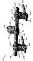
도 3은 도 2에 묘사된 할로 어셈블리의 상면도이다.3 is a top view of the halo assembly depicted in FIG. 2.
도 4a는 도 2 및 3에 묘사된 할로 어셈블리의 측면 멤버의 상면도이다.4A is a top view of the side member of the halo assembly depicted in FIGS. 2 and 3.
도 4b는 도 4a에 묘사된 측면 멤버의 하면도이다.4B is a bottom view of the side member depicted in FIG. 4A.
도 4c는 도 4b에 묘사된 측면 멤버의 단면도이다.4C is a cross-sectional view of the side member depicted in FIG. 4B.
도 4d는 도 4a-4c에 묘사된 측면 멤버의 측면도이다.4D is a side view of the side member depicted in FIGS. 4A-4C.
도 5a는 도 2 및 3에 묘사된 할로 어셈블리의 마운팅 플레이트 측면도이다.5A is a mounting plate side view of the halo assembly depicted in FIGS. 2 and 3.
도 5b는 도 5a에 묘사된 마운팅 플레이트의 상면도이다.FIG. 5B is a top view of the mounting plate depicted in FIG. 5A.
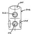
도 6a는 도 2 및 3에 묘사된 할로 어셈블리의 연결 허브 사시도이다.6A is a perspective view of a connection hub of the halo assembly depicted in FIGS. 2 and 3.
도 6b는 도 6a에 묘사된 연결 허브의 앞면 단면도이다.6B is a front sectional view of the connection hub depicted in FIG. 6A.
도 6c는 도 6a 및 6b에 나타난 연결 허브의 측면도이다.6C is a side view of the connection hub shown in FIGS. 6A and 6B.
도 7은 도 1에 묘사된 중심 조절 어셈블리의 사시도이다.7 is a perspective view of the center adjustment assembly depicted in FIG. 1.
도 8은 도 1, 2, 3 및 7에 묘사된 중심 조절 어셈블리 및 할로 어셈블리의 상면도이다.8 is a top view of the center adjustment assembly and halo assembly depicted in FIGS. 1, 2, 3 and 7.
도 9는 도 1, 2, 3 및 7에 묘사된 중심 조절 어셈블리 및 할로 어셈블리의 측면도이다.9 is a side view of the center adjustment assembly and halo assembly depicted in FIGS. 1, 2, 3 and 7.
도 10은 본 발명에 따른 중심 조절 어셈블리의 대안적 실시예이다.10 is an alternative embodiment of the center adjustment assembly according to the invention.
도 11은 수평 크로스-피스 어셈블리의 일 실시예의 사시도이다.11 is a perspective view of one embodiment of a horizontal cross-piece assembly.
도 12는 수평 크로스-피스 어셈블리의 대안적 실시예의 사시도이다.12 is a perspective view of an alternative embodiment of a horizontal cross-piece assembly.
도 13a는 수평 크로스-피스 어셈블리의 중심 클램프의 사시도이다.13A is a perspective view of a center clamp of a horizontal cross-piece assembly.
도 13b는 수평 크로스-피스 어셈블리의 중심 플램프의 정면도이다.FIG. 13B is a front view of the center clamp of the horizontal cross-piece assembly. FIG.
도 14a는 도 12에 묘사된 수평 크로스-피스 어셈블리의 회전형 확장기 클램프의 사시도이다.14A is a perspective view of the rotary expander clamp of the horizontal cross-piece assembly depicted in FIG. 12.
도 14b는 도 14a에 나타난 확장기 클래프의 단면도이다.FIG. 14B is a cross-sectional view of the dilator clap shown in FIG. 14A.
도 15a는 도 12에 묘사된 수평 크로스-피스 어셈블리의 확장기 클램프의 상부 부분의 사시도이다.15A is a perspective view of the upper portion of the dilator clamp of the horizontal cross-piece assembly depicted in FIG. 12.
도 15b는 도 15a에 묘사된 확장기 클램프의 상부 부분의 단면도이다.FIG. 15B is a cross-sectional view of the upper portion of the dilator clamp depicted in FIG. 15A.
도 15c는 도 15a에 묘사된 확장기 클램프의 상부 부분의 측면도이다.15C is a side view of the upper portion of the dilator clamp depicted in FIG. 15A.
도 16a는 도 12에 묘사된 확장기 클램프의 하부 부분의 정면도이다.16A is a front view of the lower portion of the dilator clamp depicted in FIG. 12.
도 16b는 도 16a에 묘사된 확장기 클램프의 하부 부분의 측면도이다.FIG. 16B is a side view of the lower portion of the dilator clamp depicted in FIG. 16A.
도 17은 도 1에 묘사된 턱 뼈 발판 어셈블리의 사시도이다.17 is a perspective view of the jaw bone scaffold assembly depicted in FIG. 1.
도 18은 도 1에 묘사된 광대 뼈 발판 어셈블리의 사시도이다.18 is a perspective view of the cheekbone scaffold assembly depicted in FIG. 1.
Claims (105)
Translated fromKoreanApplications Claiming Priority (3)
| Application Number | Priority Date | Filing Date | Title |
|---|---|---|---|
| US10/839,551 | 2004-05-04 | ||
| US10/839,551US7485121B2 (en) | 2004-05-04 | 2004-05-04 | Midface distractor |
| PCT/US2005/015592WO2005107620A2 (en) | 2004-05-04 | 2005-05-04 | Midface distractor |
Publications (2)
| Publication Number | Publication Date |
|---|---|
| KR20070020066A KR20070020066A (en) | 2007-02-16 |
| KR101177436B1true KR101177436B1 (en) | 2012-08-27 |
Family
ID=35240374
Family Applications (1)
| Application Number | Title | Priority Date | Filing Date |
|---|---|---|---|
| KR1020067025522AExpired - LifetimeKR101177436B1 (en) | 2004-05-04 | 2005-05-04 | Midface distractor |
Country Status (12)
| Country | Link |
|---|---|
| US (2) | US7485121B2 (en) |
| EP (1) | EP1744688B1 (en) |
| JP (1) | JP4971143B2 (en) |
| KR (1) | KR101177436B1 (en) |
| CN (1) | CN101141925B (en) |
| AU (1) | AU2005240166A1 (en) |
| BR (1) | BRPI0510602B8 (en) |
| CA (1) | CA2565397C (en) |
| ES (1) | ES2534525T3 (en) |
| NZ (1) | NZ551590A (en) |
| WO (1) | WO2005107620A2 (en) |
| ZA (1) | ZA200609966B (en) |
Families Citing this family (44)
| Publication number | Priority date | Publication date | Assignee | Title |
|---|---|---|---|---|
| US7485121B2 (en)* | 2004-05-04 | 2009-02-03 | Synthes (Usa) | Midface distractor |
| EP2085038B1 (en)* | 2008-02-01 | 2011-11-30 | Stryker Trauma SA | Ball joint for an external fixator |
| US8114077B2 (en)* | 2008-02-01 | 2012-02-14 | Stryker Trauma Sa | Clamping pin |
| EP2085037B1 (en)* | 2008-02-01 | 2013-07-24 | Stryker Trauma SA | Telescopic strut for an external fixator |
| WO2009097827A1 (en)* | 2008-02-06 | 2009-08-13 | Navas Maria Del Carmen | Orbit distractor |
| DE112009001275T5 (en)* | 2008-06-05 | 2011-04-14 | Dinkler Surgical Devices, Inc., Dayton | Head fixation device |
| DE102008034300A1 (en)* | 2008-07-23 | 2010-01-28 | Lucas Automotive Gmbh | Vehicle disc brake |
| US20100104999A1 (en)* | 2008-10-23 | 2010-04-29 | Bulloch Scott E | Apparatus, System, and Method for Intra-Oral Distraction |
| EP2405834B1 (en) | 2009-03-10 | 2016-07-20 | Stryker European Holdings I, LLC | External fixation system |
| WO2011016784A2 (en)* | 2009-08-06 | 2011-02-10 | Mohammed Aii Abbas Alkasem | Frontozygomatic anchored distraction osteogenesis device |
| US8858555B2 (en) | 2009-10-05 | 2014-10-14 | Stryker Trauma Sa | Dynamic external fixator and methods for use |
| CN101822568B (en)* | 2010-02-12 | 2012-02-15 | 中国人民解放军第四军医大学口腔医院 | Adjustable mid-face bone tractor and design method thereof |
| US9066733B2 (en) | 2010-04-29 | 2015-06-30 | DePuy Synthes Products, Inc. | Orthognathic implant and methods of use |
| US8435270B2 (en) | 2010-04-29 | 2013-05-07 | Synthes Usa, Llc | Orthognathic implant and methods of use |
| US8945128B2 (en) | 2010-08-11 | 2015-02-03 | Stryker Trauma Sa | External fixator system |
| US11141196B2 (en) | 2010-08-11 | 2021-10-12 | Stryker European Operations Holdings Llc | External fixator system |
| EP2417924B1 (en) | 2010-08-11 | 2015-07-01 | Stryker Trauma SA | External fixator system |
| US9265529B2 (en) | 2010-11-30 | 2016-02-23 | Nikolaj Wolfson | Orthopedic fixation systems and methods |
| US9265528B2 (en)* | 2010-11-30 | 2016-02-23 | Nikolaj Wolfson | Orthopedic fixation systems and methods |
| WO2013054157A1 (en)* | 2011-10-12 | 2013-04-18 | Rodriguez Gonzalez Jorge Mario | Independent multi-vector osteogenic distractor that is rigidly coupled to the craniofacial skeleton |
| US8840576B2 (en)* | 2012-03-26 | 2014-09-23 | Richard Pizzutillo | Brace installation device |
| US9101398B2 (en) | 2012-08-23 | 2015-08-11 | Stryker Trauma Sa | Bone transport external fixation frame |
| WO2014055202A1 (en)* | 2012-09-06 | 2014-04-10 | Solana Surgical LLC | External fixator |
| US9333053B2 (en) | 2013-08-07 | 2016-05-10 | Bandar ALYAMI | Orthodontic device |
| US9730731B2 (en) | 2014-02-27 | 2017-08-15 | Deka Products Limited Partnership | Craniofacial external distraction apparatus |
| FR3027791A1 (en)* | 2014-11-03 | 2016-05-06 | Yoomed | DEVICE FOR INDUCING OR CORRECTING MANDIBULAR GROWTH. |
| US10271914B2 (en) | 2015-02-11 | 2019-04-30 | University Of Utah Research Foundation | Microsurgical tool adapters, systems and related methods |
| CN104771217B (en)* | 2015-04-16 | 2017-08-04 | 高全文 | A kind of dog Middle face bone distraction device |
| CN105055005B (en)* | 2015-08-28 | 2018-04-27 | 冯志宏 | A kind of Middle face three-dimensional bone tractor |
| US10010350B2 (en) | 2016-06-14 | 2018-07-03 | Stryker European Holdings I, Llc | Gear mechanisms for fixation frame struts |
| US10245131B2 (en)* | 2016-06-28 | 2019-04-02 | John A. Cordasco | Vertical dimension of occlusion jigs used in all-on-4 dental procedures |
| CN106108992B (en)* | 2016-08-25 | 2018-11-09 | 李刚 | Bone block extension apparatus |
| CN106109021B (en)* | 2016-08-31 | 2022-06-24 | 复旦大学附属华山医院 | Adjustable curved forehead pattern guide |
| CN106264857A (en)* | 2016-08-31 | 2017-01-04 | 复旦大学附属华山医院 | Scalable arc-shaped guide rail formula eye socket traction apparatus |
| US10874433B2 (en) | 2017-01-30 | 2020-12-29 | Stryker European Holdings I, Llc | Strut attachments for external fixation frame |
| US10499897B2 (en) | 2017-03-06 | 2019-12-10 | Thompson Surgical Instruments, Inc. | Distractor with bidirectional ratchet |
| KR101862833B1 (en)* | 2017-08-21 | 2018-05-31 | 주식회사 넥스트코어 | Guide for rhinoplasty |
| RU2682615C1 (en)* | 2017-12-04 | 2019-03-19 | Александр Анатольевич Слетов | Device for fixation of mandible fragments in experimental animal |
| CN110151338B (en)* | 2019-04-26 | 2021-11-05 | 南京医科大学附属口腔医院 | An anterior maxillary distractor with adjustable direction and its clinical application |
| US20210196431A1 (en)* | 2019-10-03 | 2021-07-01 | Omar Lalani | Orthopedic device for midfacial bone structure advancement |
| CN110811797B (en)* | 2019-11-15 | 2025-06-20 | 北京大学第三医院 | An intelligent, automatic, precise, minimally invasive distraction osteogenesis system |
| CN113576633B (en)* | 2021-07-14 | 2022-07-05 | 云南省第一人民医院 | Jaw face external traction fixing support |
| US12213703B2 (en) | 2022-02-23 | 2025-02-04 | DePuy Synthes Products, Inc. | Three dimensional distractors |
| US20250221696A1 (en)* | 2024-01-07 | 2025-07-10 | Ihsan Tasci | Retraction System for Maxillofacial Surgery |
Citations (3)
| Publication number | Priority date | Publication date | Assignee | Title |
|---|---|---|---|---|
| US3072118A (en) | 1957-12-26 | 1963-01-08 | Reginald G Standerwick | Fracture appliance |
| US5524859A (en) | 1994-02-08 | 1996-06-11 | Squires; Carlton G. | Security mounting for audio equipment in a motor vehicle |
| US6423069B1 (en) | 1999-03-23 | 2002-07-23 | Synthes (Usa) | Orthopedic system having detachable bone anchors |
Family Cites Families (51)
| Publication number | Priority date | Publication date | Assignee | Title |
|---|---|---|---|---|
| US2360738A (en) | 1943-05-25 | 1944-10-17 | Holland N Stevenson | Surgeon's tool |
| US3391693A (en)* | 1966-02-11 | 1968-07-09 | Georgiade | Cranial fixation apparatus |
| US3423069A (en)* | 1967-09-29 | 1969-01-21 | Trw Inc | Airfoil |
| US3927664A (en)* | 1974-11-20 | 1975-12-23 | Univ North Carolina | Apparatus for use in the correction of maxillary and premaxillary conditions in infants |
| DE2601938C3 (en)* | 1976-01-20 | 1979-08-02 | Messerschmitt-Boelkow-Blohm Gmbh, 8000 Muenchen | Telescopically adjustable guide rail for a distraction device |
| JPS57197913A (en) | 1981-05-30 | 1982-12-04 | Shin Kobe Electric Mach Co Ltd | Triangular wave generating circuit |
| JPS6036269Y2 (en)* | 1981-06-10 | 1985-10-28 | 均 貴島 | Head cap for treatment of facial bone fractures |
| US4612930A (en)* | 1985-03-19 | 1986-09-23 | Bremer Paul W | Head fixation apparatus including crown and skull pin |
| US5147358A (en)* | 1990-10-23 | 1992-09-15 | Remmler Daniel J | Cranial fixation-distraction and positioning apparatus and method |
| DE4219156A1 (en) | 1992-06-11 | 1993-12-16 | Leibinger Gmbh | Jaw-bone-positioning equipment - has connecting component between bases on bones which can be made rigid or flexible, typically elastic hose filled with hardening plastics material |
| US5885283A (en)* | 1992-08-04 | 1999-03-23 | Gittleman; Neal B. | Osteogenic mandibular distention apparatus and method |
| US5364396A (en)* | 1993-03-29 | 1994-11-15 | Robinson Randolph C | Distraction method and apparatus |
| DE4316794C1 (en)* | 1993-05-19 | 1994-10-13 | Joerg Bischof | Device for the distraction of bones |
| US5766173A (en)* | 1993-06-10 | 1998-06-16 | Texas Scottish Rite Hospital For Children | Distractor mechanism for external fixation device |
| US6187004B1 (en)* | 1993-07-14 | 2001-02-13 | Jeffrey A. Fearon | Subcutaneous bone expansion device |
| US5529358A (en)* | 1994-09-30 | 1996-06-25 | Ohio Medical Instrument Company | Bifurcated surgical retractor |
| DE29501880U1 (en)* | 1995-02-06 | 1995-05-24 | Karl Leibinger Medizintechnik GmbH & Co. KG, 78570 Mühlheim | Bone extension device |
| FR2731348B1 (en)* | 1995-03-09 | 1997-04-11 | Proteor Sa | HALO CONSISTS OF ELEMENTS ADJUSTABLE IN POSITION AND SUITABLE TO BE FIXED IN A PLURALITY OF ADJUSTABLE POSITIONS ON THE SKULL OF A PATIENT |
| WO1997012568A1 (en)* | 1995-10-02 | 1997-04-10 | Remmler Daniel J | Implantable apparatus, matrix and method for correction of craniofacial bone deformities |
| EP0770359A1 (en)* | 1995-10-05 | 1997-05-02 | Medicon e.G. Chirurgiemechaniker-Genossenschaft | Distraction device for bone segments |
| DE19538323A1 (en)* | 1995-10-14 | 1997-04-17 | Mueller Paul A | Traction device for correction of an upper jaw |
| US5846245A (en)* | 1995-10-20 | 1998-12-08 | New York University | Bone-adjusting device |
| EP0865258B1 (en)* | 1995-12-01 | 2000-06-21 | David A. Walker | Telescopic bone plate for use in bone lengthening by distraction osteogenesis |
| US5885387A (en)* | 1995-12-08 | 1999-03-23 | Sumitomo Rubber Industries, Ltd. | Pneumatic tire having endless carcass cord ply |
| US5672177A (en)* | 1996-01-31 | 1997-09-30 | The General Hospital Corporation | Implantable bone distraction device |
| BE1010602A4 (en) | 1996-09-04 | 1998-11-03 | Mommaerts Maurice Yves | Apparatus for intra-oral distractieosteotomie. |
| US5895387A (en)* | 1996-10-09 | 1999-04-20 | Romulo Guerrero | Method of craniofacial bone distraction |
| US5976142A (en)* | 1996-10-16 | 1999-11-02 | Chin; Martin | Apparatus and method for distraction osteogenesis of small alveolar bone |
| US5769850A (en)* | 1996-10-16 | 1998-06-23 | Chin; Martin | Apparatus and method for submergible, self-retaining distraction osteogenesis |
| US5885290A (en)* | 1996-12-09 | 1999-03-23 | Guerrero; Cesar A. | Intra-oral bone distraction device |
| US6159210A (en)* | 1997-01-14 | 2000-12-12 | Research Corporation Technologies, Inc. | Bone fixation pin with rotary cutting tip |
| US6113599A (en)* | 1997-06-04 | 2000-09-05 | Kalpa Engineering, Inc. | Apparatus for internal mandibular distraction |
| WO1999004715A1 (en)* | 1997-07-21 | 1999-02-04 | Roger Minoretti | Intraoral distractor for callus distraction in the lower jaw |
| US6152925A (en)* | 1998-03-04 | 2000-11-28 | University Of Iowa Research Foundation | Method and apparatus for external fixation of an elbow |
| US6171313B1 (en)* | 1998-07-02 | 2001-01-09 | Yan Razdolsky | Distraction apparatus for subapical osteotomy and vertical segment distraction and ridge augmentation |
| DE19856062A1 (en)* | 1998-12-04 | 2000-06-15 | Wittenstein Gmbh & Co Kg | Distraction device |
| EP1027868A1 (en)* | 1999-02-09 | 2000-08-16 | Paul A. Dr. med. Müller | Traction device for the adjustment of an upper jaw |
| US6547796B1 (en)* | 1999-05-20 | 2003-04-15 | Walter Lorenz Surgical, Inc. | Midface mobilizing instrument |
| US6383189B1 (en)* | 1999-09-13 | 2002-05-07 | Brian Schumacher | Driver tool for bone distractor with shaft extension |
| US6277124B1 (en)* | 1999-10-27 | 2001-08-21 | Synthes (Usa) | Method and apparatus for ratcheting adjustment of bone segments |
| WO2001041662A1 (en)* | 1999-12-09 | 2001-06-14 | Macropore | Completely resorbable connective tissue distraction devices and techniques |
| US6293947B1 (en)* | 2000-01-28 | 2001-09-25 | Daniel Buchbinder | Distraction osteogenesis device and method |
| US6471706B1 (en)* | 2000-04-18 | 2002-10-29 | Walter Lorenz Surgical, Inc. | Resorbable bone distractor and method |
| AR033840A1 (en)* | 2000-10-04 | 2004-01-07 | Synthes Ag | AN ORTHOPEDIC DEVICE TO MODIFY THE DISTANCE BETWEEN THE MAXILAR AND THE CIGOMA OF A PATIENT |
| US6908469B2 (en)* | 2000-10-04 | 2005-06-21 | Synthes (Usa) | Compact maxillary distractor |
| US6659972B2 (en)* | 2001-02-02 | 2003-12-09 | Rose-Hulman Institute Of Technology | Halo orthosis |
| US6860883B2 (en)* | 2002-02-11 | 2005-03-01 | Pioneer Laboratories, Inc. | External fixation apparatus and method |
| US7615051B2 (en)* | 2003-02-21 | 2009-11-10 | Synthes Usa, Llc | Craniofacial fracture reduction assembly |
| US7011642B2 (en)* | 2003-04-07 | 2006-03-14 | Kls-Martin, L.P. | External fixation device for cranialmaxillofacial distraction |
| US7730563B1 (en)* | 2004-03-29 | 2010-06-08 | Frederick Sklar | Head support and stabilization system |
| US7485121B2 (en) | 2004-05-04 | 2009-02-03 | Synthes (Usa) | Midface distractor |
- 2004
- 2004-05-04USUS10/839,551patent/US7485121B2/ennot_activeExpired - Lifetime
- 2005
- 2005-05-04WOPCT/US2005/015592patent/WO2005107620A2/enactiveApplication Filing
- 2005-05-04AUAU2005240166Apatent/AU2005240166A1/ennot_activeAbandoned
- 2005-05-04KRKR1020067025522Apatent/KR101177436B1/ennot_activeExpired - Lifetime
- 2005-05-04ESES05746832.4Tpatent/ES2534525T3/ennot_activeExpired - Lifetime
- 2005-05-04CNCN2005800226488Apatent/CN101141925B/ennot_activeExpired - Lifetime
- 2005-05-04NZNZ551590Apatent/NZ551590A/enunknown
- 2005-05-04CACA2565397Apatent/CA2565397C/ennot_activeExpired - Lifetime
- 2005-05-04ZAZA200609966Apatent/ZA200609966B/enunknown
- 2005-05-04EPEP05746832.4Apatent/EP1744688B1/ennot_activeExpired - Lifetime
- 2005-05-04JPJP2007511582Apatent/JP4971143B2/ennot_activeExpired - Lifetime
- 2005-05-04BRBRPI0510602Apatent/BRPI0510602B8/enactiveIP Right Grant
- 2008
- 2008-12-19USUS12/339,165patent/US8172849B2/enactiveActive
Patent Citations (3)
| Publication number | Priority date | Publication date | Assignee | Title |
|---|---|---|---|---|
| US3072118A (en) | 1957-12-26 | 1963-01-08 | Reginald G Standerwick | Fracture appliance |
| US5524859A (en) | 1994-02-08 | 1996-06-11 | Squires; Carlton G. | Security mounting for audio equipment in a motor vehicle |
| US6423069B1 (en) | 1999-03-23 | 2002-07-23 | Synthes (Usa) | Orthopedic system having detachable bone anchors |
Also Published As
| Publication number | Publication date |
|---|---|
| WO2005107620A3 (en) | 2007-03-15 |
| CN101141925B (en) | 2012-09-26 |
| AU2005240166A1 (en) | 2005-11-17 |
| BRPI0510602B1 (en) | 2017-07-11 |
| BRPI0510602B8 (en) | 2021-06-22 |
| NZ551590A (en) | 2010-08-27 |
| CN101141925A (en) | 2008-03-12 |
| EP1744688A4 (en) | 2011-03-09 |
| ES2534525T3 (en) | 2015-04-24 |
| CA2565397C (en) | 2012-12-18 |
| US20050251136A1 (en) | 2005-11-10 |
| KR20070020066A (en) | 2007-02-16 |
| US7485121B2 (en) | 2009-02-03 |
| EP1744688B1 (en) | 2015-01-21 |
| WO2005107620A2 (en) | 2005-11-17 |
| US8172849B2 (en) | 2012-05-08 |
| JP2007536001A (en) | 2007-12-13 |
| CA2565397A1 (en) | 2005-11-17 |
| BRPI0510602A (en) | 2007-10-30 |
| JP4971143B2 (en) | 2012-07-11 |
| ZA200609966B (en) | 2008-06-25 |
| EP1744688A2 (en) | 2007-01-24 |
| US20090131944A1 (en) | 2009-05-21 |
Similar Documents
| Publication | Publication Date | Title |
|---|---|---|
| KR101177436B1 (en) | Midface distractor | |
| TWI617295B (en) | Hinged fixation devices for combined upper jaw correction | |
| EP2467076B1 (en) | Transverse rod connector | |
| US6322566B1 (en) | Intraoral distractor for callus distraction in the lower jaw | |
| EP1499250B1 (en) | Compact maxillary distractor | |
| JPH09511918A (en) | Device and method for posterior spinal fusion | |
| JP2008501396A (en) | Device for correcting skeletal deformation | |
| US11090160B2 (en) | Orthognathic implant assembly and method of use | |
| US7862566B2 (en) | Midface external distraction method and apparatus | |
| EP1322243B1 (en) | Maxillary distractor | |
| US9867638B2 (en) | Transport distraction apparatus | |
| US7347687B2 (en) | Distraction apparatus for orthodontic, orthognathic and oral/maxillofacial surgery applications on the mandible | |
| WO2013054157A1 (en) | Independent multi-vector osteogenic distractor that is rigidly coupled to the craniofacial skeleton | |
| US20210196431A1 (en) | Orthopedic device for midfacial bone structure advancement | |
| CA2179588C (en) | An assembly tool for assembling a mandibular distraction device | |
| HK1055664B (en) | Maxillary distractor |
Legal Events
| Date | Code | Title | Description |
|---|---|---|---|
| PA0105 | International application | Patent event date:20061204 Patent event code:PA01051R01D Comment text:International Patent Application | |
| PG1501 | Laying open of application | ||
| A201 | Request for examination | ||
| PA0201 | Request for examination | Patent event code:PA02012R01D Patent event date:20100503 Comment text:Request for Examination of Application | |
| PE0902 | Notice of grounds for rejection | Comment text:Notification of reason for refusal Patent event date:20111108 Patent event code:PE09021S01D | |
| E701 | Decision to grant or registration of patent right | ||
| PE0701 | Decision of registration | Patent event code:PE07011S01D Comment text:Decision to Grant Registration Patent event date:20120622 | |
| GRNT | Written decision to grant | ||
| PR0701 | Registration of establishment | Comment text:Registration of Establishment Patent event date:20120821 Patent event code:PR07011E01D | |
| PR1002 | Payment of registration fee | Payment date:20120821 End annual number:3 Start annual number:1 | |
| PG1601 | Publication of registration | ||
| FPAY | Annual fee payment | Payment date:20150716 Year of fee payment:4 | |
| PR1001 | Payment of annual fee | Payment date:20150716 Start annual number:4 End annual number:4 | |
| FPAY | Annual fee payment | Payment date:20160720 Year of fee payment:5 | |
| PR1001 | Payment of annual fee | Payment date:20160720 Start annual number:5 End annual number:5 | |
| FPAY | Annual fee payment | Payment date:20170719 Year of fee payment:6 | |
| PR1001 | Payment of annual fee | Payment date:20170719 Start annual number:6 End annual number:6 | |
| FPAY | Annual fee payment | Payment date:20180718 Year of fee payment:7 | |
| PR1001 | Payment of annual fee | Payment date:20180718 Start annual number:7 End annual number:7 | |
| PR1001 | Payment of annual fee | Payment date:20190718 Start annual number:8 End annual number:8 | |
| PR1001 | Payment of annual fee | Payment date:20200715 Start annual number:9 End annual number:9 | |
| PR1001 | Payment of annual fee | Payment date:20210715 Start annual number:10 End annual number:10 | |
| PR1001 | Payment of annual fee | Payment date:20220718 Start annual number:11 End annual number:11 | |
| PR1001 | Payment of annual fee | Payment date:20230705 Start annual number:12 End annual number:12 | |
| PR1001 | Payment of annual fee | Payment date:20240703 Start annual number:13 End annual number:13 |