KR101176152B1 - Snap-lock for drill sleeve - Google Patents
Snap-lock for drill sleeveDownload PDFInfo
- Publication number
- KR101176152B1 KR101176152B1KR1020067026802AKR20067026802AKR101176152B1KR 101176152 B1KR101176152 B1KR 101176152B1KR 1020067026802 AKR1020067026802 AKR 1020067026802AKR 20067026802 AKR20067026802 AKR 20067026802AKR 101176152 B1KR101176152 B1KR 101176152B1
- Authority
- KR
- South Korea
- Prior art keywords
- sleeve
- bone
- drill
- hole
- sleeves
- Prior art date
- Legal status (The legal status is an assumption and is not a legal conclusion. Google has not performed a legal analysis and makes no representation as to the accuracy of the status listed.)
- Expired - Fee Related
Links
Images


Classifications
- A—HUMAN NECESSITIES
- A61—MEDICAL OR VETERINARY SCIENCE; HYGIENE
- A61B—DIAGNOSIS; SURGERY; IDENTIFICATION
- A61B17/00—Surgical instruments, devices or methods
- A61B17/16—Instruments for performing osteoclasis; Drills or chisels for bones; Trepans
- A61B17/17—Guides or aligning means for drills, mills, pins or wires
- A61B17/1725—Guides or aligning means for drills, mills, pins or wires for applying transverse screws or pins through intramedullary nails or pins
- A—HUMAN NECESSITIES
- A61—MEDICAL OR VETERINARY SCIENCE; HYGIENE
- A61B—DIAGNOSIS; SURGERY; IDENTIFICATION
- A61B17/00—Surgical instruments, devices or methods
- A61B17/16—Instruments for performing osteoclasis; Drills or chisels for bones; Trepans
- A61B17/17—Guides or aligning means for drills, mills, pins or wires
- A—HUMAN NECESSITIES
- A61—MEDICAL OR VETERINARY SCIENCE; HYGIENE
- A61B—DIAGNOSIS; SURGERY; IDENTIFICATION
- A61B17/00—Surgical instruments, devices or methods
- A61B17/16—Instruments for performing osteoclasis; Drills or chisels for bones; Trepans
- A—HUMAN NECESSITIES
- A61—MEDICAL OR VETERINARY SCIENCE; HYGIENE
- A61B—DIAGNOSIS; SURGERY; IDENTIFICATION
- A61B17/00—Surgical instruments, devices or methods
- A61B17/16—Instruments for performing osteoclasis; Drills or chisels for bones; Trepans
- A61B17/1613—Component parts
- A61B17/1615—Drill bits, i.e. rotating tools extending from a handpiece to contact the worked material
- A—HUMAN NECESSITIES
- A61—MEDICAL OR VETERINARY SCIENCE; HYGIENE
- A61B—DIAGNOSIS; SURGERY; IDENTIFICATION
- A61B17/00—Surgical instruments, devices or methods
- A61B17/16—Instruments for performing osteoclasis; Drills or chisels for bones; Trepans
- A61B17/17—Guides or aligning means for drills, mills, pins or wires
- A61B17/1728—Guides or aligning means for drills, mills, pins or wires for holes for bone plates or plate screws
- A—HUMAN NECESSITIES
- A61—MEDICAL OR VETERINARY SCIENCE; HYGIENE
- A61B—DIAGNOSIS; SURGERY; IDENTIFICATION
- A61B90/00—Instruments, implements or accessories specially adapted for surgery or diagnosis and not covered by any of the groups A61B1/00 - A61B50/00, e.g. for luxation treatment or for protecting wound edges
- A61B90/90—Identification means for patients or instruments, e.g. tags
- A61B90/94—Identification means for patients or instruments, e.g. tags coded with symbols, e.g. text
- A—HUMAN NECESSITIES
- A61—MEDICAL OR VETERINARY SCIENCE; HYGIENE
- A61B—DIAGNOSIS; SURGERY; IDENTIFICATION
- A61B17/00—Surgical instruments, devices or methods
- A61B17/16—Instruments for performing osteoclasis; Drills or chisels for bones; Trepans
- A61B17/17—Guides or aligning means for drills, mills, pins or wires
- A61B17/1735—Guides or aligning means for drills, mills, pins or wires for rasps or chisels
- A—HUMAN NECESSITIES
- A61—MEDICAL OR VETERINARY SCIENCE; HYGIENE
- A61B—DIAGNOSIS; SURGERY; IDENTIFICATION
- A61B90/00—Instruments, implements or accessories specially adapted for surgery or diagnosis and not covered by any of the groups A61B1/00 - A61B50/00, e.g. for luxation treatment or for protecting wound edges
- A61B90/06—Measuring instruments not otherwise provided for
- A61B2090/062—Measuring instruments not otherwise provided for penetration depth
- A—HUMAN NECESSITIES
- A61—MEDICAL OR VETERINARY SCIENCE; HYGIENE
- A61B—DIAGNOSIS; SURGERY; IDENTIFICATION
- A61B90/00—Instruments, implements or accessories specially adapted for surgery or diagnosis and not covered by any of the groups A61B1/00 - A61B50/00, e.g. for luxation treatment or for protecting wound edges
- A61B90/08—Accessories or related features not otherwise provided for
- A61B2090/0801—Prevention of accidental cutting or pricking
- A61B2090/08021—Prevention of accidental cutting or pricking of the patient or his organs
- A—HUMAN NECESSITIES
- A61—MEDICAL OR VETERINARY SCIENCE; HYGIENE
- A61B—DIAGNOSIS; SURGERY; IDENTIFICATION
- A61B90/00—Instruments, implements or accessories specially adapted for surgery or diagnosis and not covered by any of the groups A61B1/00 - A61B50/00, e.g. for luxation treatment or for protecting wound edges
- A61B90/90—Identification means for patients or instruments, e.g. tags
- A61B90/92—Identification means for patients or instruments, e.g. tags coded with colour
Landscapes
- Health & Medical Sciences (AREA)
- Surgery (AREA)
- Life Sciences & Earth Sciences (AREA)
- Medical Informatics (AREA)
- Animal Behavior & Ethology (AREA)
- Veterinary Medicine (AREA)
- Oral & Maxillofacial Surgery (AREA)
- Engineering & Computer Science (AREA)
- Biomedical Technology (AREA)
- Heart & Thoracic Surgery (AREA)
- Public Health (AREA)
- Molecular Biology (AREA)
- Nuclear Medicine, Radiotherapy & Molecular Imaging (AREA)
- General Health & Medical Sciences (AREA)
- Orthopedic Medicine & Surgery (AREA)
- Dentistry (AREA)
- Pathology (AREA)
- Surgical Instruments (AREA)
- Drilling Tools (AREA)
- Processing Of Stones Or Stones Resemblance Materials (AREA)
Abstract
Description
Translated fromKorean본 발명은 드릴 슬리브 시스템에 관한 것이다. 보다 상세하게는 본 발명은 나사 삽입 슬리브에 드릴 슬리브를 일시적으로 지지하기 위한 스냅 링 디자인에 관한 것이다.The present invention relates to a drill sleeve system. More particularly, the present invention relates to a snap ring design for temporarily supporting a drill sleeve in a threaded sleeve.
플레이트와 같은 외과정형 고정장치는 흔히 장치 내의 구멍을 통해 삽입된 조임쇠로 뼈에 결합된다. 상완골 또는 대퇴골과 같은 긴뼈의 골절에 대해서, 골절은 골수내고정관 내에 뚫린 채널 내로 연장부재를 삽입함으로써 치료될 수 있다. 이 연장부재 또는 "골수내고정못"은 해당 기술분야에 공지된 것처럼 골절된 뼛조각이 함께 치유될 때까지 뼈에 안정성을 제공할 수 있다. 골수내고정못은 뼈에 조여질 수 있으며, 뼈 안에서 골수내고정못은 못 안에 미리 형성된 구멍을 통해 삽입된 나사를 이용하여 유지된다. 상응하는 구멍이 인접한 뼈에 천공되어 뼈 안에 나사를 용이하게 삽입하게 할 수 있다. 이러한 구멍은 목표 나사구멍과 정렬된 드릴 가이드의 도움으로 형성될 수 있다. 드릴은 드릴 가이드를 통해 안내될 수 있으며 따라서 나사구멍을 통해 유도되어 나사구멍 아래에 있는 뼈 내에 구멍을 천공한다.Surgical orthopedic fixtures, such as plates, are often coupled to bone with fasteners inserted through holes in the device. For fractures of long bones, such as the humerus or the femur, the fracture can be treated by inserting an elongate member into a channel drilled in the intramedullary canal. This elongate member or “intramedullary nail” can provide stability to the bone until the fractured bone fragments heal together, as is known in the art. Intramedullary nails can be screwed into the bone, and the intramedullary nails in the bone are maintained using screws inserted through preformed holes in the nail. Corresponding holes may be drilled in adjacent bones to facilitate insertion of screws into the bones. This hole can be formed with the aid of a drill guide aligned with the target screw hole. The drill may be guided through the drill guide and thus guided through the screw hole to drill the hole in the bone below the screw hole.
골수내고정못을 설치하고 결착 조임쇠를 삽입할 때 발생하는 절개 총수 및 길이를 줄이기 위한 노력으로, 천공 및 나사삽입공정은 피부를 통해서 수행될 수 있다. 따라서, 절개는 뼈 위에 놓인 피부에 수행될 수 있으며, 투관침이 절개부 내로 삽입되어 뼈의 아래로 초기 경로를 생성하기 위해 연한 조직을 분리하는데 사용될 수 있다. 드릴은 드릴 슬리브를 통해 삽입되어 이전에 설명한 뼈 내의 구멍을 형성하는데 사용될 수 있다. 나사삽입 슬리브는 이후 상기 경로를 통해 삽입되어 나사구멍 및 뼈와 나사를 맞물리게 하는 것을 돕는데 사용될 수 있다. 유리하게는, 이러한 세 부품(투관침, 드릴 슬리브, 나사삽입 슬리브)은 외과의사의 취급 및 사용을 돕기 위해서 하나의 유닛으로 제공될 수 있다. 따라서, 이러한 세 부품은 서로에 대해 포개져서 단일한 유닛으로 삽입될 수 있다.In an effort to reduce the total number and length of incisions that occur when installing intramedullary nails and inserting fasteners, perforation and screwing processes can be performed through the skin. Thus, an incision can be made to the skin over the bone and a trocar can be inserted into the incision to separate soft tissue to create an initial path down the bone. The drill can be inserted through the drill sleeve and used to form the holes in the bone described previously. The threading sleeve can then be inserted through the path to be used to help engage the screw with the screw hole and bone. Advantageously, these three parts (trocar, drill sleeve, threading sleeve) can be provided in one unit to assist the surgeon in handling and using. Thus, these three parts can be superimposed on one another and inserted into a single unit.
이러한 세 부품 유닛의 사용을 더욱 돕기 위해서, 이 부품 중 두 개 이상은 사용자에 의해 취급하는 동안 개별 부품의 분리를 방지하는데 도움이 되는 구조를 가질 수 있다. 예를 들어, 스냅 링, 볼 멈춤쇠, 또는 실이 상기 부품을 함께 고정하는데 사용될 수 있다. 한 부품을 다른 부품으로부터 제거하기 위해서(예를 들어, 나사삽입 슬리브로부터 드릴 슬리브를 제거하기 위해서), 사용자는 상기 부품을 멀리 당길 수 있으며(스냅 링 또는 볼 멈춤쇠의 경우), 또는 상기 부품에서 실을 빼낼 수 있다(실을 꿴 부품이 제공된 경우).To further aid in the use of these three component units, two or more of these components may have a structure that helps prevent separation of the individual components during handling by the user. For example, snap rings, ball detents, or seals can be used to secure the parts together. To remove one part from another (eg to remove a drill sleeve from a threaded sleeve), the user can pull the part away (in the case of a snap ring or ball detent), or at the part The thread can be pulled out (if threaded parts are provided).
스냅 링 잠금장치는 살균이 어려울 수 있으며, 실을 꿴 부품은 외과적인 환경에서 다루기 어려울 수 있다. 따라서 시스템의 두 개 이상의 부품을 서로에 대해 임시로 유지하기 위한 단순하고 살균이 쉬운 디자인을 가지며, 사용자가 원할 때 이들 부품으로부터 쉽게 분리될 수 있는 다중 부품 드릴 슬리브 시스템에 대한 요구가 존재한다.Snap ring locks can be difficult to sterilize, and threaded parts can be difficult to handle in surgical environments. Thus, there is a need for a multi-part drill sleeve system that has a simple, easy-to-sterile design for temporarily holding two or more parts of the system relative to each other and that can be easily separated from these parts when desired by the user.
외과정형 시스템은 길이방향 구멍 및 표면을 한정하는 내부 표면 및 외부 표면을 구비한 제1 슬리브 부재; 및 길이방향 구멍을 한정하는 내부 표면 및 외부 표면을 구비하는 제2 슬리브 부재를 포함하고, 상기 제2 슬리브 부재는 상기 제1 슬리브 부재의 구멍 내에 적어도 부분적으로 수용되도록 구성되는 것으로 개시된다. 상기 제1 및 제2 슬리브 부재 중 하나의 길이방향 구멍은 뼈 안에 구멍을 천공하기 위해 자신을 통과하는 드릴 비트를 수용하도록 구성될 수 있다. 더욱이, 상기 제1 및 제2 슬리브 중 하나는 돌출부를 포함하고 다른 하나는 상응하는 리세스를 구비하고, 상기 돌출부와 리세스는 상기 제2 슬리브 부재가 상기 제1 슬리브 부재의 구멍 내에 적어도 부분적으로 수용될 때 상기 제1 및 제2 슬리브 부재를 잠정적으로 축방향으로 함께 잠그도록 연동될 수 있다. 상기 제2 슬리브는 상기 제1 및 제2 슬리브 사이에 축방향 분리력을 가하고 상기 제2 슬리브의 적어도 일부에 반경방향 압축력을 가합으로써 상기 제1 슬리브 부재로부터 맞물림이 해제 가능할수 있다.The orthopedic system includes a first sleeve member having an inner surface and an outer surface defining a longitudinal hole and a surface; And a second sleeve member having an inner surface and an outer surface defining a longitudinal hole, wherein the second sleeve member is configured to be configured to be at least partially received within the hole of the first sleeve member. The longitudinal hole of one of the first and second sleeve members may be configured to receive a drill bit passing through it to drill the hole in the bone. Moreover, one of the first and second sleeves includes a protrusion and the other has a corresponding recess, wherein the protrusion and the recess are such that the second sleeve member is at least partially within the aperture of the first sleeve member. When received, the first and second sleeve members may interlock to temporarily lock together in an axial direction. The second sleeve may be disengaged from the first sleeve member by applying an axial separation force between the first and second sleeves and applying a radial compressive force to at least a portion of the second sleeve.
상기 시스템은 또한 상기 제2 슬리브의 길이방향 구멍 내에 수용되도록 구성된 투관침(torcar)을 포함할 수 있다. 상기 제1 및 제2 슬리브 부재는 각각 플랜지 부재를 포함하는 인접 단부 및 테이퍼진 첨단 영역을 포함하는 말단 단부를 더 구비할 수 있다. 상기 제1 슬리브의 길이방향 구멍은 드라이버 및 뼈 조임쇠를 수용하여 상기 구멍의 길이방향 축을 따르는 방향으로 상기 조임쇠를 뼈 안으로 삽입하도록 구성될 수 있다. 더욱이 상기 제1 및 제2 슬리브 부재 중 적어도 하나의 테이퍼진 첨단부는 뼈 고정 엘리먼트 내의 조임쇠 구멍과 정렬되도록 구성될 수 있다. 상기 뼈 고정 엘리먼트는 본 플레이트 또는 골수내고정못일 수 있다.The system may also include a trocar configured to be received in the longitudinal hole of the second sleeve. The first and second sleeve members may further comprise distal ends including adjacent ends comprising flange members and tapered tip regions, respectively. The longitudinal hole of the first sleeve may be configured to receive a driver and a bone fastener and to insert the fastener into the bone in a direction along the longitudinal axis of the hole. Furthermore, the tapered tip of at least one of the first and second sleeve members can be configured to align with fastener holes in the bone fixation element. The bone fixation element may be a bone plate or intramedullary nail.
상기 돌출부는 상기 결합된 슬리브와 일체형으로 형성될 수 있으며, 일실시예에서 하나 이상의 원주방향 융기부를 포함할 수 있다. 상기 리세스는 상기 하나 이상의 융기부에 상응하는 하나 이상의 원주방향 홈을 포함할 수 있다. 상기 돌출부는 제1 및 제2 테이퍼진 표면을 포함할 수 있다.The protrusion may be integrally formed with the combined sleeve, and in one embodiment may comprise one or more circumferential ridges. The recess may include one or more circumferential grooves corresponding to the one or more ridges. The protrusion may comprise first and second tapered surfaces.
상기 제2 슬리브는 상기 슬리브의 내부 및 외부 표면 사이에 배치된 하나 이상의 길이방향 슬롯을 포함하고, 상기 슬롯은 상기 슬리브의 하나 이상의 단부로부터 길이를 가지고 형성되고, 상기 슬롯은 상기 슬리브의 적어도 일부를 축방향으로 유연하게 하도록 구성될 수 있다.The second sleeve includes one or more longitudinal slots disposed between the inner and outer surfaces of the sleeve, the slots having a length from one or more ends of the sleeve, the slots defining at least a portion of the sleeve; It can be configured to be axially flexible.
상기 적어도 하나의 슬롯은 상기 슬리브의 제1 단부를 제1 및 제2 반쪽으로 분할하고, 상기 제1 및 제2 반쪽을 서로를 향해 가압하면 상기 융기부를 상기 리세스로부터 맞물림을 해제하고, 그로 인해 상기 제1 및 제2 슬리브가 서로에 대해 축방향으로 맞물리거나 맞물림이 해제되게 할 수 있다.The at least one slot divides the first end of the sleeve into first and second halves, and pressing the first and second halves towards each other releases the ridge from the recess, thereby The first and second sleeves can be axially engaged or disengaged from each other.
상기 제2 슬리브는 상기 슬리브의 원주 둘레로 서로에 대해 지름 방향으로 배치된 두 개의 길이방향 슬롯을 구비할 수 있다. 상기 돌출부는 상기 슬리브가 상기 제1 슬리브의 구멍 안으로 삽입될 때 상기 제2 슬리브의 반경방향 압박을 돕도록 구성된 하나 이상의 테이퍼진 표면을 포함할 수 있다.The second sleeve may have two longitudinal slots disposed radially relative to each other about the circumference of the sleeve. The protrusion may comprise one or more tapered surfaces configured to assist radial compression of the second sleeve when the sleeve is inserted into a hole in the first sleeve.
상기 제1 및 제2 슬리브 및 상기 투관침은 상기 제1 슬리브의 구멍을 통해 수용될 수 있는 뼈나사 크기의 시각적 표식을 제공하기 위해 색깔이 코딩될 수 있다.The first and second sleeves and trocars may be color coded to provide a visual indication of bone screw size that can be received through the aperture of the first sleeve.
상기 제1 슬리브의 외부 표면은 골수내고정못의 보조 암의 구멍 내에 수용되어 상기 슬리브를 상기 골수내고정못의 일부 내의 목표 조임쇠 구멍에 정렬시키도록 구성될 수 있다.The outer surface of the first sleeve may be configured to be received in a hole in the secondary arm of the intramedullary nail to align the sleeve with a target fastener hole in a portion of the intramedullary nail.
외과정형 시스템은 인접 및 말단 단부, 길이방향 축 및 내부 및 외부 표면을 구비한 제1 슬리브를 포함하는 것으로 제공된다.The orthopedic system is provided comprising a first sleeve having adjacent and distal ends, a longitudinal axis and an inner and outer surface.
제2 슬리브는 인접 및 말단 단부, 길이방향 축 및 내부 및 외부 표면을 구비하고, 상기 내부 표면이 상기 제1 슬리브의 적어도 일부를 수용하도록 구성된다. 상기 내부 표면은 뼈 조임쇠 및 드라이버를 수용하여 상기 조임쇠를 뼈 내에 뚫린 구멍 안으로 삽입하도록 구성될 수 있다. 상기 제1 및 제2 슬리브 부재 중 하나의 내부 표면은 뼈 안에 구멍을 천공하기 위해 드릴 비트를 수용하도록 구성될 수 있다. 상기 제1 슬리브의 적어도 일부는 상기 제2 슬리브의 적어도 일부 내에 미끄럼 가능하게 수용 가능할 수 있다.The second sleeve has adjacent and distal ends, a longitudinal axis and an inner and outer surface, the inner surface configured to receive at least a portion of the first sleeve. The inner surface may be configured to receive a bone fastener and a driver to insert the fastener into a hole drilled in the bone. The inner surface of one of the first and second sleeve members may be configured to receive a drill bit to drill a hole in the bone. At least a portion of the first sleeve may be slidably receivable in at least a portion of the second sleeve.
상기 제2 슬리브 내부 표면 및 상기 제1 슬리브 외부 표면 중 하나는 돌출부를 포함하고 다른 하나는 상응하는 리세스를 포함하여 상기 제1 슬리브가 상기 제2 슬리브 내에 수용될 때 상기 돌출부 및 리세스가 상기 제1 슬리브를 상기 제2 슬리브에 해제 가능하도록 축방향으로 맞물리게 연동될 수 있다.One of the second sleeve inner surface and the first sleeve outer surface includes a protrusion and the other includes a corresponding recess such that the protrusion and the recess are formed when the first sleeve is received within the second sleeve. The first sleeve may be interlocked with the second sleeve to be axially engaged.
상기 돌출부는 상기 결합된 슬리브와 일체형으로 형성될 수 있다. 상기 돌출부는 하나 이상의 원주방향 융기부 또는 다수의 불연속한 돌출 엘리먼트를 포함할 수 있다. 상기 돌출부는 상기 제2 슬리브의 내부 표면의 일부와 맞물리도록 구성된 제1 및 제2 테이퍼진 표면을 포함할 수 있다.The protrusion may be integrally formed with the coupled sleeve. The protrusion may comprise one or more circumferential ridges or a plurality of discontinuous projecting elements. The protrusion may include first and second tapered surfaces configured to engage a portion of the inner surface of the second sleeve.
상기 슬리브는 상기 제1 및 제2 슬리브 사이에 축방향 분리력을 가하고 상기 제1 슬리브의 적어도 일부에 압축력을 가하여 서로로부터 분리 가능할 수 있다.The sleeve may be detachable from each other by applying an axial separation force between the first and second sleeves and applying a compressive force to at least a portion of the first sleeve.
상기 시스템은 상기 제1 슬리브의 길이방향 구멍 내에 수용되도록 구성된 투관침을 더 포함할 수 있다. 상기 슬리브는 각각 플랜지 부재를 포함하는 인접 단부 및 테이퍼진 첨단 영역을 포함하는 말단 단부를 더 구비할 수 있다. 상기 제1 및 제2 슬리브 중 적어도 하나의 테이퍼진 첨단부는 뼈 고정 엘리먼트 내의 조임쇠 구멍과 정렬되도록 구성될 수 있다. 상기 뼈 고정 엘리먼트는 본 플레이트 또는 골수내고정못일 수 있다.The system may further comprise a trocar configured to be received in a longitudinal hole of the first sleeve. The sleeve may further have a distal end comprising an adjacent end and a tapered tip region, each including a flange member. The tapered tip of at least one of the first and second sleeves may be configured to align with fastener holes in the bone fixation element. The bone fixation element may be a bone plate or intramedullary nail.
상기 제1 슬리브는 상기 슬리브의 내부 및 외부 표면 사이에 배치된 하나 이상의 길이방향 슬롯을 포함하고, 상기 슬롯은 상기 슬리브의 하나 이상의 단부로부터 길이를 가지고 형성되고, 상기 슬롯은 상기 슬리브의 적어도 일부를 축방향으로 유연하게 하도록 구성될 수 있다. 상기 적어도 하나의 슬롯은 상기 제1 슬리브의 제1 단부를 제1 및 제2 반쪽으로 분할하고, 상기 제1 슬리브가 상기 제2 슬리브 내로 완전히 수용될 때 상기 제1 및 제2 반쪽을 서로를 향해 가압하면 상기 융기부를 상기 리세스로부터 맞물림을 해제하고, 그로 인해 상기 제1 슬리브가 상기 제2 슬리브로부터 제거되게 할 수 있다.The first sleeve comprises one or more longitudinal slots disposed between the inner and outer surfaces of the sleeve, the slots having a length from one or more ends of the sleeve, the slots defining at least a portion of the sleeve; It can be configured to be axially flexible. The at least one slot divides the first end of the first sleeve into first and second halves, and the first and second halves towards each other when the first sleeve is fully received into the second sleeve. Pressing may release the ridge from the recess, thereby causing the first sleeve to be removed from the second sleeve.
상기 제1 슬리브가 상기 제2 슬리브 내로 삽입될 때, 상기 제1 테이퍼진 표면은 상기 제1 및 제2 반쪽을 함께 반경방향으로 압박하도록 상기 제2 슬리브의 내부 표면과 연동될 수 있다. 상기 제1 슬리브는 상기 슬리브의 원주 둘레로 서로에 대해 지름 방향으로 배치된 두 개의 길이방향 슬롯을 구비할 수 있다. 상기 돌출부는 상기 슬리브가 상기 제1 슬리브의 구멍 안으로 삽입될 때 상기 제1 슬리브의 반경방향 압박을 돕도록 구성된 하나 이상의 테이퍼진 표면을 포함할 수 있다.When the first sleeve is inserted into the second sleeve, the first tapered surface may be interlocked with the inner surface of the second sleeve to radially press the first and second halves together. The first sleeve may have two longitudinal slots disposed radially relative to each other about the circumference of the sleeve. The protrusion may comprise one or more tapered surfaces configured to assist radial compression of the first sleeve when the sleeve is inserted into a hole in the first sleeve.
상기 제1 및 제2 슬리브 및 상기 투관침은 상기 제1 슬리브의 구멍을 통해 수용될 수 있는 뼈나사의 크기의 시각적 표식을 제공하기 위해 색깔이 코딩될 수 있다.The first and second sleeves and the trocar may be color coded to provide a visual indication of the size of the bone screw that can be received through the aperture of the first sleeve.
더욱이, 상기 제1 슬리브의 외부 표면은 골수내고정못의 보조 암의 구멍 내에 수용되어 상기 슬리브를 상기 골수내고정못의 일부 내의 목표 조임쇠 구멍에 정렬시키도록 구성될 수 있다.Moreover, an outer surface of the first sleeve may be received in the hole of the secondary arm of the intramedullary nail and configured to align the sleeve with a target fastener hole in a portion of the intramedullary nail.
뼈 내에 구멍을 뚫기 위한 방법은: (a) 드릴 슬리브 및 보호 슬리브 조합을 제공하되, 상기 드릴 슬리브는 상기 보호 슬리브의 적어도 일부 내에 포개는 방식으로 수용 가능하고, 상기 드릴 슬리브는 뼈 내에 구멍을 뚫기 위한 드릴 비트를 수용하기 위한 내부 표면을 구비하고, 상기 드릴 슬리브는 상기 슬리브를 잠정적으로 축방향으로 함께 잠그기 위해서 상기 보호 슬리브의 내부 표면상에 배치된 상응하는 리세스 또는 돌출부와 맞물리도록 구성된 돌출부 및 리세스 중 하나를 포함하는 외부 표면을 구비하는, 단계; 상기 드릴 및 보호 슬리브는 상기 슬리브 사이에 축??항 분리력을 가하고 상기 드릴 슬리브의 적어도 일부에 반경방향 압축력을 가함으로써 서로로부터 분리 가능하고, (b) 상기 드릴 슬리브 및 보호 슬리브 조합을 환자의 절개부를 통해 진입시키는 단계; (c) 상기 드릴 슬리브 및 보호 슬리브를 상기 뼈의 일부 위에 있는 뼈 고정 엘리먼트와 정렬되도록 진입시키는 단계; (d) 상기 드릴 슬리브를 통해서 드릴 비트를 삽입하고 상기 드릴 비트를 뼈와 맞물리도록 진입시키는 단계; (e) 상기 뼈 내에 구멍을 형성하기 위해 상기 드릴을 회전시키는 단계; (f) 상기 드릴 슬리브로부터 상기 드릴 비트를 제거하는 단계; 및 (g) 상기 드릴 슬리브 및 상기 보호 슬리브 사이에 축방향 분리력을 가하고 상기 드릴 슬리브의 일부에 반경방향 압축력을 가하여 서로의 맞물림을 해제하는 단계를 포함하도록 구성된다.A method for drilling a hole in a bone comprises: (a) providing a drill sleeve and a protective sleeve combination, the drill sleeve being receivable in a manner nested within at least a portion of the protective sleeve, the drill sleeve drilling a hole in the bone A protrusion configured to engage a corresponding recess or protrusion disposed on the inner surface of the protective sleeve to secure the drill bit for the drill sleeve, and to lock the sleeve together provisionally axially; Having an outer surface comprising one of the recesses; The drill and protective sleeve are separable from each other by exerting an axial separation force between the sleeves and applying a radial compressive force to at least a portion of the drill sleeve, and (b) cutting the drill sleeve and protective sleeve combination into the patient's incision. Entering through wealth; (c) entering the drill sleeve and protective sleeve to align with a bone fixation element over a portion of the bone; (d) inserting a drill bit through the drill sleeve and entering the drill bit to engage the bone; (e) rotating the drill to form a hole in the bone; (f) removing the drill bit from the drill sleeve; And (g) applying an axial separation force between the drill sleeve and the protective sleeve and applying a radial compressive force to a portion of the drill sleeve to disengage each other.
상기 드릴 슬리브 및 보호 슬리브는 상기 드릴 슬리브의 길이방향 구멍 내에 수용되도록 구성된 투관침을 더 포함할 수 있다. 상기 슬리브는 각각 플랜지 부재를 포함하는 인접 단부 및 테이퍼진 첨단 영역을 포함하는 말단 단부를 구비할 수 있다. 상기 뼈 고정 엘리먼트는 본 플레이트 또는 골수내고정못일 수 있다. 상기 돌출부는 상기 결합된 슬리브와 일체형으로 형성될 수 있다. 상기 돌출부는 다수의 불연속한 돌출 엘리먼트를 포함할 수 있다. 상기 돌출부는 하나 이상의 원주방향 융기부를 포함할 수 있다. 상기 리세스는 상기 하나 이상의 융기부에 상응하는 하나 이상의 원주방향 홈을 포함할 수 있다. 상기 돌출부는 상기 리세스의 일부와 맞물리도록 구성된 제1 및 제2 테이퍼진 표면을 포함할 수 있다.The drill sleeve and protective sleeve may further comprise a trocar configured to be received in a longitudinal hole of the drill sleeve. The sleeve may have a distal end including a proximal end and a tapered tip region, each comprising a flange member. The bone fixation element may be a bone plate or intramedullary nail. The protrusion may be integrally formed with the coupled sleeve. The protrusion may comprise a plurality of discontinuous projecting elements. The protrusion may comprise one or more circumferential ridges. The recess may include one or more circumferential grooves corresponding to the one or more ridges. The protrusion may include first and second tapered surfaces configured to engage a portion of the recess.
상기 드릴 슬리브는 상기 슬리브의 내부 및 외부 표면 사이에 배치된 하나 이상의 길이방향 슬롯을 포함하고, 상기 슬롯은 상기 슬리브의 하나 이상의 단부로부터 길이를 가지고 형성되고, 상기 슬롯은 상기 슬리브의 일부를 반경방향으로 유연하게 하도록 구성될 수 있다. 상기 하나 이상의 슬롯은 상기 드릴 슬리브의 제1 단부를 제1 및 제2 반쪽으로 분할하고, 상기 드릴 슬리브가 상기 나사 삽입 슬리브 내로 완전히 수용될 때 상기 제1 및 제2 반쪽을 서로를 향해 가압하면 상기 돌출부를 상기 리세스로부터 맞물림 해제하고, 그로 인해 상기 드릴 슬리브가 상기 나사 삽입 슬리브로부터 제거되게 할 수 있다.The drill sleeve includes one or more longitudinal slots disposed between the inner and outer surfaces of the sleeve, the slots are formed having a length from one or more ends of the sleeve, the slots radially extending a portion of the sleeve. Can be configured to be flexible. The one or more slots divide the first end of the drill sleeve into first and second halves and press the first and second halves towards each other when the drill sleeve is fully received into the threaded sleeve. The protrusion can be disengaged from the recess, thereby causing the drill sleeve to be removed from the threaded insert sleeve.
상기 방법은 (g) 상기 보호 슬리브를 통해서 뼈 조임쇠 및 스크루드라이버를 삽입하는 단계; 및 (h) 상기 뼈 고정 엘리먼트를 상기 뼈에 고정하기 위해서 상기 뼈 내의 구멍으로 상기 뼈 조임쇠를 삽입하는 단계를 더 포함할 수 있다.The method comprises the steps of: (g) inserting a bone fastener and a screwdriver through the protective sleeve; And (h) inserting the bone fastener into a hole in the bone to secure the bone fixation element to the bone.
상기 방법은 상기 단계 (a) 및 단계 (b) 사이에, 골수내고정못에 부착된 보조 암 내의 구멍으로 상기 보호 슬리브의 외부 표면을 삽입하는 단계를 더 포함하고, 상기 단계 (c)는 상기 뼈 고정 엘리먼트 내의 조임쇠 구멍에 정렬되도록 상기 보조 암 내의 구멍을 통해 상기 보호 슬리브 및 드릴 슬리브를 진입시키는 단계를 포함하고, 상기 단계 (e)는 상기 골수내고정못 내의 조임쇠 구멍을 통해 상기 뼈 내에 구멍을 뚫는 단계를 포함할 수 있다.The method further comprises inserting the outer surface of the protective sleeve between the steps (a) and (b) into a hole in the auxiliary arm attached to the intramedullary nail, wherein step (c) comprises Entering the protective sleeve and the drill sleeve through the holes in the auxiliary arm to align with the fastener holes in the fastening element, the step (e) drilling a hole in the bone through the fastener holes in the intramedullary nail. It may include a step.
상기 방법은 (h) 상기 보호 슬리브를 통해서 뼈 조임쇠 및 스크루드라이버를 삽입하는 단계; (i) 상기 뼈 고정 엘리먼트를 상기 뼈에 고정하기 위해서 상기 뼈 내의 구멍으로 상기 뼈 조임쇠를 삽입하는 단계; 및 (j) 상기 환자로부터 상기 보호 슬리브를 제거하는 단계를 더 포함할 수 있다.The method includes (h) inserting a bone fastener and a screwdriver through the protective sleeve; (i) inserting the bone fastener into a hole in the bone to secure the bone fixation element to the bone; And (j) removing the protective sleeve from the patient.
본 발명의 바람직한 특징은 첨부된 도면에 개시되어 있으며, 여기서 유사한 참조부호는 몇몇 도면을 통해 유사한 구성요소를 나타낸다. 도면에서:Preferred features of the invention are set forth in the accompanying drawings, wherein like reference numerals designate like elements throughout the several views. In the drawing:
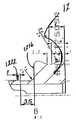
도 1은 본 발명의 보호 슬리브, 드릴 슬리브 및 투관침 장치를 도시하는 단면조립도:1 is a cross-sectional view illustrating the protective sleeve, drill sleeve and trocar device of the present invention:
도 2a 및 2b는 도 1의 장치의 투관침 엘리먼트를 도시하는 측면도 및 상세도;2A and 2B are side and detail views of the trocar element of the apparatus of FIG. 1;
도 3a 내지 도 3e는 도 1의 장치의 드릴 슬리브를 각각 도시하는 측면도, 상면도, 부분상세도 및 상세도;3A-3E are side, top, partial and detailed views, respectively, of the drill sleeve of the apparatus of FIG. 1;
도 4a, 4b 및 4c는 도 1의 장치의 보호 슬리브를 각각 도시하는 측면도, 단면도 및 상세단면도;4A, 4B and 4C are side, sectional and detailed sectional views, respectively, showing the protective sleeve of the device of FIG. 1;
도 5a 및 5b는 대안적인 유지특성 디자인을 채용한 도 3a의 드릴 슬리브를 도시하는 측면도 및 단면도;5A and 5B show side and cross-sectional views of the drill sleeve of FIG. 3A employing an alternative retention design;
도 6a 및 6b는 도 5a 및 5b의 드릴 슬리브 유지특성 디자인에 사용하기 위한 도 4a의 보호 슬리브를 도시하는 측면도 및 단면도;6A and 6B are side and cross-sectional views illustrating the protective sleeve of FIG. 4A for use in the drill sleeve retention design of FIGS. 5A and 5B;
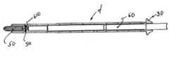
도 7은 도 1의 장치에 사용하기 위한 예시적인 드릴 비트를 도시하는 측면도;7 is a side view illustrating an exemplary drill bit for use in the apparatus of FIG. 1;
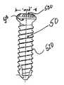
도 8은 도 1의 장치에 사용하기 위한 예시적인 뼈나사를 도시하는 측면도;8 is a side view showing an exemplary bone screw for use in the device of FIG. 1;
도 9는 투관침을 구비하지 않고 드릴 슬리브를 통해 삽입된 도 7의 드릴 비트를 구비한 도 1의 장치를 도시하는 단면도;9 is a cross-sectional view of the device of FIG. 1 with the drill bit of FIG. 7 inserted through a drill sleeve without a trocar; FIG.
도 10은 투관침 및 드릴 슬리브를 구비하지 않고 보호 슬리브를 통해 삽입된 나사 및 스크루드라이버를 구비한 도 1의 시스템을 도시하는 단면도;FIG. 10 is a cross-sectional view of the system of FIG. 1 with screws and screwdrivers inserted through a protective sleeve without a trocar and drill sleeve; FIG.
도 11a 내지 도 11c는 대퇴골 내에 삽입된 골수내고정못 조립체의 보조 암으로 사용되는 도 1의 장치를 도시하는 사시도;11A-11C are perspective views showing the device of FIG. 1 used as an auxiliary arm of an intramedullary nail assembly inserted into the femur;
도 12a 및 12b는 도 4a 내지 4c의 보호 슬리브로 이용하기 위한 와이어 가이 드 슬리브를 도시하는 측면도 및 단면도;12A and 12B are side and cross-sectional views showing a wire guide sleeve for use as the protective sleeve of FIGS. 4A-4C;
도 13은 도 4a 내지 4c의 보호 슬리브로 이용되는 드릴을 도시하는 부분단면도; 및FIG. 13 is a partial cross-sectional view showing a drill used as the protective sleeve of FIGS. 4A-4C. And
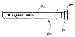
도 14는 도 4a 내지 4c의 보호 슬리브 및 도 12a 및 12b의 와이어 가이드 슬리브로 사용하기 위한 가이드 와이어를 도시하는 단면도.14 is a cross-sectional view showing a guide wire for use with the protective sleeve of FIGS. 4A-4C and the wire guide sleeve of FIGS. 12A and 12B.
드릴링 및 나사삽입 슬리브 장치는 본 플레이트, 골수내고정못 등과 같은 외과정형 고정장치를 인체 해부학의 뼛조각에 고정하기 위한 조임쇠를 설치하는데 사용하는 것으로 개시된다. 이러한 고정 장치는 골절된 뼈를 치료하는데 사용될 수 있으며 또는 약한 뼈의 골절을 방지하기 위해 설치될 수 있다. 도 1은 투관침(10), 드릴 슬리브(20) 및 보호 슬리브(30)를 포함하는, 이러한 사용을 위한 예시적인 장치(1)를 도시한다. 도시된 것처럼, 투관침(10), 드릴 슬리브(20) 및 보호 슬리브(30)는 단일한 유닛으로 외과 절개를 통해 안내되게 하는 포개진 구조를 갖는다. 따라서, 상기 장치(1)가 뼈 내에 구멍을 뚫거나 나사를 배치하는데 사용될 때, 상기 장치(1)는 플레이트, 못 등의 하나 또는 그 이상의 뼈나사 구멍의 바로 위에 있는 환자의 피부를 통해 만들어진 단일한 절개부를 통해서 삽입될 수 있다. 상기 시스템의 개별적인 구성요소는 이후 원하는 공정을 수행하는데 필요하다면 제거될 수 있다. 예를 들어, 상기 투관침(10)은 상기 장치(1)가 대체로 환자의 뼈 또는 고정장치의 나사구멍과 접촉하도록 배치된 후 제거될 수 있다.Drilling and screwing sleeve devices are disclosed for use in installing fasteners for securing surgical orthopedic fixtures, such as bone plates, intramedullary nails, and the like, to bone fragments of human anatomy. Such fixation devices may be used to treat fractured bones or may be installed to prevent fracture of weak bones. 1 shows an exemplary device 1 for this use, including a
도 1에 도시된 것처럼, 상기 장치(1)는 근접 사용자 단부(2), 말단 절개단 부(3), 및 상기 보호 슬리브(30)의 외부 표면에 의해 일반적으로 형성된 일반적으로 원통형의 길이방향 중앙부(4)를 구비한다. 상기 인접 단부(2)는 사용자가 쉽게 쥘 수 있도록 형성되고, 상기 말단 단부(3)는 환자의 절개부 내로의 삽입을 용이하게 하는 테이퍼진 구성을 가질 수 있다.As shown in FIG. 1, the device 1 has a generally cylindrical longitudinal center portion generally formed by a
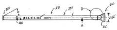
도 2a 및 2b를 참조하면, 상기 투관침(10)은 외경 "td", 길이방향 축 "A-A", 및 길이 "tl"를 갖는 원통형 중앙부(130) 및 근접 및 말단 단부(110, 120)를 구비하는 봉형상 부재를 포함한다. 상기 근접 단부(110)는 증가된 지름 "tfd"을 갖는 플랜지 엘리먼트(112), 및 사용자가 쉽게 쥐도록 구성된 외부 파지 표면(114)을 포함할 수 있다. 상기 플랜지 엘리먼트(112)는 인접 단면(116) 및 말단면(118)을 더 포함할 수 있다. 상기 인접 단면(116)은 손의 엄지손가락 또는 손바닥에 의해 가해질 수 있는 것처럼 사용자의 가압력을 받도록 구성될 수 있으며, 반면 상기 말단면(118)은 드릴 슬리브 플랜지(212)의 인접면(214)과 맞물려 사용자가 가하는 가압력을 그쪽으로 전달하도록 구성될 수 있다.2A and 2B, the
상기 투관침 플랜지 엘리먼트(112)는 특별한 크기를 갖는 것으로 투관침을 구별하기 위해 적용되는 색깔 밴드를 갖는 하나 또는 그 이상의 환형 홈(119)을 구비할 수 있다. 다시 말하면, 본 발명의 시스템이 다양한 크기 중 하나에 제공될 수 있으므로, 상기 시스템 크기에 대해 사용자에게 명확한 시각적 표식을 제공하기 위해 상기 장치 엘리먼트의 단순한 칼라 코딩을 제공하는 것이 유리할 수 있다. 따라서, 홈(119)은 동일한 시스템 사이즈를 갖는 드릴 슬리브(20), 보호 슬리브(30) 및 드릴(40)에 제공된 유사한 색깔 밴드에 부합하는 색깔 밴드를 구비할 수 있다. 색깔은 페인팅 또는 다른 유사한 기술에 의해 상기 홈(119)에 적용될 수 있다.The
상기 투관침 말단 단부(120)는 환자의 절개부 내에 쉽게 삽입되도록 테이퍼질 수 있다. 상기 테이퍼는 길이방향 축 "A-A"에 대해서 각도(θ)를 형성할 수 있으며, 이 각도는 예시적인 실시예에서는 대략 30도이고, 다른 각도가 제공될 수 있다. 상기 말단부(120)는 주변의 조직을 통해서 투관침(10)의 이동을(드릴 슬리브(20) 및 보호 슬리브(30)와 마찬가지로) 더욱 돕기 위해서 뾰족한 점을 형성하는 첨단부(122)를 구비할 수 있다. 사용 중에, 상기 첨단부(122)는 절개부 내로 또한 절개부를 통해서 가압될 때 연한 조직을 분리하는데 사용될 수 있다.The trocar
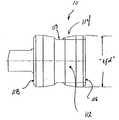
도 3a 내지 도 3e를 참조하면, 예시적인 드릴 슬리브(20)는 길이방향 축 "B-B" 및 길이 "dsl"를 갖는 원통형 중앙부(230)와 근접단부 및 말단부((210, 220)를 구비하는 것으로 도시된다. 상기 드릴 슬리브(20)는 지름 "dod"을 갖는 외부 원통면(232), 및 길이 "dsl"을 따라 형성된 길이방향 구멍(236)을 한정하는 길이 "did"를 갖는 내부 원통면(234)을 더 구비할 수 있다.3A-3E, an
상기 드릴 슬리브 구멍(236)은 도 1에 도시된 것처럼 시스템(1)의 일부로서 환자 내부로 상기 슬리브(20)가 삽입되는 동안 투관침(10)의 원통형 중앙부(130)를 수용하는 크기를 가질 수 있다. 상기 구멍(236)은 또한 상기 슬리브(20)가 절개부를 통해 일단 안내되면 길이방향 축 "B-B"을 따라서 상기 드릴 슬리브(20)를 통해 아래에 놓인 뼈를 천공하는 것을 허용하기 위해서 적절한 크기의 드릴 비트(40)(도 7 및 도 9 참조)를 수용하는 크기를 가질 수 있다.The
상기 드릴 슬리브(20)의 인접 단부(210)는 슬리브 외경 "dod"보다 더 큰 지름 "dsfd"를 갖는 플랜지(212)를 포함할 수 있다. 상기 플랜지(212)는 투관침이 상기 드릴 슬리브(20) 내로 완전히 삽입될 때 투관침(10)의 말단 단부면(118)과 맞물리도록 구성된 인접 단부면(214)을 더 구비할 수 있다(도 1 참조). 상기 플랜지(212)는 상기 보호 슬리브(30)의 인접 환형 단부면(314)과 맞물리도록 구성된 말단 단부면(216)을 더 구비할 수 있으며(도 1 및 도 4b 참조), 이는 이후에 보다 상세하게 설명된다.
도 3a에 도시된 것처럼, 상기 드릴 슬리브(20) 내로 투관침(10)을 삽입하는 것을 돕기 위해서, 구멍(236)이 상기 슬리브 인접 단부(210)에 바로 근접한 지점에 외측 방향으로 약간 테이퍼질 수 있다.As shown in FIG. 3A, to assist in inserting the
상기 드릴 슬리브 플랜지(212)는 사용자가 쉽게 잡을 수 있도록 구성된 외부 파지 표면(218)을 구비할 수 있다. 예시적인 실시예에서, 상기 인접 단부면(214)의 외경은 말단 단부면(216)의 외경보다 더 커서, 그 사이에 배치된 파지 표면(218)이 말단 방향으로 약간 면하도록 경사진다. 파지 표면(218)은 또한 사용자의 손가락이 보호 슬리브(30)와 맞물림에서 벗어나도록 드릴 슬리브(20)를 당기도록 적용될 때 사용자의 손가락에 보다 가깝게 합치되도록 약간 오목하다.The
드릴 슬리브 말단부(220)는 환자의 절개부 내로 더 쉽게 삽입되도록 테이퍼질 수 있다. 상기 테이퍼는 길이방향 축 "B-B"에 대하여 각도(α)를 형성할 수 있으며, 이는 예시적인 실시예에서 대략 30도이고, 실질적으로 투관침 말단부(120)의 각도(θ)에 부합한다. 상기 길이 "dsl"은 투관침(10)이 드릴 슬리브의 구멍(236) 을 통해 삽입될 때 첨단부(122)가 드릴 슬리브(20)의 말단 단부(220)을 넘어서 말단으로 거리 "x"만큼 연장되게 할 수 있다(도 1 참조). 상기 거리 "x"는 투관침(10) 및 드릴 슬리브(20)의 테이퍼진 단부(122)(220)가 두 부품이 환자의 절개부에 삽입하거나 진입하는 것을 도울 수 있는 하나의 상대적으로 부드러운 테이퍼진 표면을 형성하는데 상응하도록 선택될 수 있다.The drill sleeve
상기 드릴 슬리브(20)는 취급 및 설치 중에 보호 슬리브(30) 내에 드릴 슬리브를 잠정적으로 축방향으로 연결하도록 잠금 구조를 더 구비할 수 있다. 이러한 잠금 구조는 앞서 언급한 것처럼 드릴 및 보호 슬리브 플랜지(212)(312)(도 4a) 사이에 손가락 압력을 가함으로써 쉽게 극복될 수 있다. 도 3a 및 3c에 도시된 실시예에서, 상기 잠금 구조는 말단 단부 플랜지(212)에 인접하게 배치된 원주방향 융기부(2000)를 포함한다. 도 3c에 도시된 것처럼, 융기부(2000)는 제1 및 제2 테이퍼진 표면(2010)(2020) 및 높이 "h"를 갖는 상부 표면(2030)을 구비할 수 있다. 상기 제1 및 제2 테이퍼진 표면(2010)(2020)은 드릴 슬리브(20)의 길이방향 축 "B-B"에 대하여 테이퍼 각도(γ)(σ)로 경사질 수 있다. 상기 테이퍼(2010)(2020)는 후에 보다 상세히 설명되는 것처럼 내부 리세스(3000)(도 4c)와 상기 원주방향 융기부를 부드럽게 맞물리거나 맞물림을 해제하게 한다. 맞물림/맞물림 해제를 보다 용이하게 하기 위해서, 테이퍼진 표면 하나 또는 모두는 또한 약간 오목하게 될 수 있다. 따라서, 상기 드릴 슬리브(20)가 보호 슬리브(30) 내로 삽입될 때, 제1 테이퍼진 표면(2010)은 보호 슬리브(30)의 내부 표면(334)과 맞물려 드릴 슬리브(20)의 인접 단부(210)에 부드러운 압박을 제공할 수 있다. 상기 융기부(2000)가 리세 스(3000)에 완전히 맞물리기만 하면, 제2 테이퍼진 표면(2020)은 보호 슬리브(30) 내의 리세스(3000)의 인접 단부벽(3010)과 접촉하여 정상적인 취급동안 보호 슬리브(30)의 인접 단부(210) 밖으로 드릴 슬리브(20)가 빠지는 것을 막을 수 있다.The
일실시예에서(도 3c), 상기 제2 표면 테이퍼 각도(σ)는 제1 표면 테이퍼 각도(γ)보다 더 커서, 결과적으로 부품(20)(30) 사이의 맞물리는 힘을 상대적으로 더 작게 요구하고 부품의 분리를 위한 맞물림 해제력을 약간 더 크게 할 수 있다. 상기 융기부(3000)가 동일하지 않은 제1 및 제2 테이퍼 각도(γ)(σ)를 가진 것으로 설명되었지만, 상기 드릴 슬리브(20)는 동일한 테이퍼를 가질 수 있음을 유의해야 한다(도 5b 참조).In one embodiment (FIG. 3C), the second surface taper angle σ is greater than the first surface taper angle γ, resulting in a relatively smaller engagement force between the
γ는 대략 5도 내지 대략 90도일 수 있으며, 일실시예에서 γ는 대략 30도이다. σ는 대략 1도 내지 대략 90도일 수 있으며, 일실시예에서 σ는 대략 5도이다. 융기부 높이 "rh"는 대략 0.2mm 내지 대략 1.0mm일 수 있으며, 일실시예에서 대략 0.4mm이다.γ can be from about 5 degrees to about 90 degrees, and in one embodiment γ is about 30 degrees. [sigma] can be about 1 degree to about 90 degrees, and in one embodiment [sigma] is about 5 degrees. The ridge height “rh” can be approximately 0.2 mm to approximately 1.0 mm, in one embodiment approximately 0.4 mm.
도 3a에 도시된 것처럼, 한 쌍의 길이방향 슬롯(2050)(2060)이 드릴 슬리브 인접 단부(210) 내에 직경 방향으로 반대 위치에 제공되어 드릴 슬리브(20)에 압박을 가함으로써 상기 원주방향 융기부(2000)가 보호 슬리브 리세스(3000)와 맞물릴 수 있게 할 수 있다. 따라서, 상기 슬롯(2050)은 상기 드릴 슬리브의 인접 단부(210)를 제1 및 제2 대향하는 반쪽(2110)(2120)으로 분할할 수 있으며, 이는 서로를 향하여 구부러져 드릴 슬리브(20)를 보호 슬리브(30)에 설치하거나 그로부터 제거하는 동안 원주방향 융기부(2000)의 외경을 일시적으로 줄일 수 있다.As shown in FIG. 3A, a pair of longitudinal slots 2050 and 2060 are provided in the radially opposite position in the drill sleeve
도 3a에 도시된 것처럼, 상기 슬롯(2050)(2060)은 상기 드릴 슬리브 인접 단부(210)로부터 상기 슬리브 인접 및 말단 단부(210)(220) 사이의 위치까지 형성될 수 있다. 상기 슬롯(2050)(2060)은 길이 "sl" 및 폭 "sw"을 가질 수 있으며, 그 말단 단부에서 응력감소 확대 절개부(2070)를 가질 수 있으며, 이는 예시적인 실시예에서 원형 절개부이다. 슬롯 길이 "sl"은 대략 20mm 내지 대략 150mm일 수 있으며, 일실시예에서 대략 65m이다. 슬롯 폭 "sw"는 대략 0.5mm 내지 대략 3.0mm이며, 일실시예에서 대략 1.0mm이다.As shown in FIG. 3A, the slots 2050 and 2060 may be formed from the drill sleeve
도 3a의 드릴 슬리브가 한 쌍의 슬롯(2050)(2060)을 구비한 것으로 설명되었지만, 드릴 슬리브(20)는 원하는 대로 하나 또는 그 이상의 슬롯을 구비할 수 있음을 유의해야 한다. 더욱이, 하나 이상의 슬롯이 사용된 경우, 이 슬롯은 서로 다른 길이 및/또는 폭을 가질 수 있다. 또한, 상기 슬롯은 각각의 길이를 따라서 변하는 폭을 가질 수 있다.Although the drill sleeve of FIG. 3A has been described as having a pair of slots 2050 and 2060, it should be noted that the
도 3a 및 도 3e에 도시된 것처럼, 측부 플랫(2080)(2090)이 드릴 슬리브 인접 단부(210)에 근접한 드릴 슬리브의 외부 표면(232)상에 제공될 수 있다. 이 플랫(2080)(2090)은 180도의 간격으로 배치될 수 있으며, 상기 드릴 슬리브(20)를 보호 슬리브(20) 내로 삽입하는 것을 더욱 돕기 위해서 슬롯(2050)(2060)의 가운데 위치할 수 있다. 상기 슬롯(2050)(2060)이 단지 드릴 슬리브(20)를 일차원으로만 압박하기 때문에, 상기 플랫(2080)(2090)은 슬롯(2050)(2060)에 근접한 보호 슬리브(30)의 내부 표면(334)과 원주방향 융기부(2000) 사이에 남은 계면을 제거한다. 상기 드릴 슬리브(20)에 두 개 이상의 슬롯을 제공하면 슬리브를 이차원으로 압박 할 수 있으며, 따라서 상기 측부 플랫(2080)(2090)이 필요 없을 수 있다는 것을 유의해야 한다.As shown in FIGS. 3A and 3E,
투관침(10)에서와 마찬가지로, 상기 드릴 슬리브(20)는 특별한 크기의 드릴 비트에 상응하도록 상기 슬리브를 구별하기 위해서 색깔로 코딩될 수 있다. 따라서, 상기 중앙 원통형 부분(230)은 색깔 밴드가 적용될 수 있는 외부 표면(232) 내에 형성된 환형 홈(232)을 구비할 수 있다. 적용된 색깔은 상기 드릴 슬리브(20)의 구멍(236) 내에 수용되는 크기를 가진 투관침(10)에 적용된 색깔에 부합할 수 있다.As with
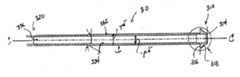
도 4a 내지 도 4c를 참조하면, 예시적인 보호 슬리브(30)는 인접 및 말단 단부(310)(320), 및 길이방향 축 "C-C"와 길이 "psl"를 가진 중앙 원통형 부분(330)을 구비하는 것으로 도시된다. 상기 보호 슬리브(30)는 지름 "pod"을 가진 외부 원통형 표면(332) 및 상기 길이 "psl"을 따라 형성된 길이방향 구멍을 형성하는 직경 "pid"를 가진 내부 원통형 표면(334)을 더 구비할 수 있다.4A-4C, an exemplary
상기 보호 슬리브 구멍(336)은 도 1에 도시된 것처럼 시스템(1)의 일부로서 슬리브(20)(30)를 환자 내에 삽입하는 동안 드릴 슬리브(20)의 원통형 중앙 부분(230)을 수용하는 크기를 가질 수 있다. 상기 구멍(336)은 또한 적절한 크기의 나사(50) 및 스크루드라이버(60)(도 10)를 수용하는 크기를 가져서 상기 슬리브(30)가 절개부를 통해 안내되기만 하면 상기 슬리브 길이방향 축 "C-C"을 따라 보호 슬리브(30)를 통해서 아래에 있는 구멍 내로 나사를 삽입하는 것을 도울 수 있다. 따라서, 상기 내부 지름 "pid"은 나사, 나선형 칼날 또는 헬리컬 칼날을 삽 입하도록 대략 1.0mm 내지 대략 17.0mm가 될 수 있다. 이러한 칼날에 대한 추가적인 설명이 2002년 10월 15일에 로스 등(Roth et al.)이 출원한 "외과정형 이식 삽입 기구(Orthopedic Implant Insertion Instruments)"라는 제목을 가진 계류중인 미국 정규특허출원 제 10/269,976호에 개시되어 있으며, 이는 전체가 본 출원에 참조로서 병합된다. 구체적으로, 상기 보호 슬리브(30)는 대략 1mm 내지 대략 8mm의 주 지름을 가지며 대략 1.0mm 내지 대략 12.0mm의 머리 지름을 갖는 나사를 수용할 수 있다.The
상기 보호 슬리브(30)의 인접 단부(310)는 슬리브 외부 지름 "pod"보다 더 큰 지름 "psfd"를 갖는 플랜지(312)를 포함할 수 있다. 상기 플랜지(312)는 드릴 슬리브가 보호 슬리브(30)에 완전히 삽입될 때 상기 드릴 슬리브(20)의 말단 단면(216)에 맞물리도록 구성된 인접 단면(314)을 더 구비할 수 있다(도 1 참조). 상기 플랜지(312)는 사용자가 쥘 수 있게 구성된 말단 단면(316)을 더 구비할 수 있다.The
상기 보호 슬리브 플랜지(312)는 상기 인접 및 말단 단면(314)(316) 사이에 배치되고 사용자가 쉽게 쥐도록 구성된 외부 파지면(318)을 더 구비할 수 있다. 예시적인 실시예에서, 상기 인접 단면(314)의 외부 지름은 말단 단면(316)의 외부 지름보다 더 작으며, 이로 인해 그 사이에 배치된 상기 파지면(318)은 말단 방향으로 약간 면하도록 경사진다. 파지면(318)은 또한 상기 드릴 슬리브(20)를 보호 슬리브(30)와의 맞물림이 해제되도록 당기는 동안 상기 슬리브(30)를 고정하도록 가해지는 사용자의 손가락에 보다 가깝게 합치되도록 약간 오목하게 형성될 수 있다.The
도 4b 및 도 4c에 도시되고 상기 드릴 슬리브(20)의 원주방향 융기부(2000)와 관련하여 이미 설명한 것처럼, 상기 보호 슬리브(30)는 슬리브 인접 단부(310)에 근접한 구멍(336) 내에 배치된 리세스(3000)를 더 구비할 수 있다. 상기 리세스(3000)는 드릴 슬리브가 상기 보호 슬리브(30) 내에 완전히 삽입될 때 상기 드릴 슬리브(20)의 원주방향 융기부(2000)와 맞물리도록 구성될 수 있다. 상기 리세스(3000)는 지름 "rd"를 가지며, 상기 리세스(3000)와 구멍(336) 사이에 전이를 제공하는 인접 및 말단 단면(3010)(3020)을 구비할 수 있다. 리세스 지름은 상기 원주방향 융기부(2000)와 원하는 계면 및 잠금을 제공하도록 대략 0.2mm 내지 대략 1.0mm의 리세스 깊이 "rd"를 제공하는 크기를 가질 수 있다. 일실시예에서, 상기 리세스 깊이 "rd"는 대략 0.6mm이다. 더욱이, 상기 드릴 슬리브(20)를 보호 슬리브(30) 내로 삽입하는 것을 돕기 위해서, 상기 구멍(336)은 슬리브 인접 단부(310)에 바로 근접하게 바깥으로 약간 테이퍼질 수 있다.As shown in FIGS. 4B and 4C and already described with respect to the
상기 보호 슬리브 말단 단부(320)는 환자의 절개부 내로 보다 쉽게 삽입되도록 테이퍼질 수 있다. 상기 테이퍼는 길이방향 축 "C-C"에 대해서 각도(β)를 형성할 수 있으며, 이는 예시적인 실시예에서 30도이고, 투관침 및 드릴 슬리브 말단 단부(120)(220)의 각도(θ)(α)에 실질적으로 부합한다. 더욱이, 상기 길이 "psl"는 드릴 슬리브(20)가 보호 슬리브의 구멍(336)을 통해 삽입될 때 상기 말단 단부(220)가 보호 슬리브(30)의 말단 단부(320)을 넘어서 거리 "y"만큼 연장하도록 설정될 수 있다(도 1 참조). 이 거리 "y"는 투관침(10), 드릴 슬리브(20) 및 보호 슬리브의 테이퍼진 단부(122)(220)(320)가 환자의 절개부 내에 두 부품을 삽입하거 나 진입하는 것을 도울 수 있는 하나의 상대적으로 부드러운 테이퍼진 표면을 형성하는데 상응하도록 선택될 수 있다.The protective sleeve
도 5a 내지 도 5c는 대안적인 보호 슬리브(1300)(도 6a 및 도 6b 참조) 내의 상응하는 리세스(1322)와 맞물리도록 구성된 상승된 원주방향 융기부(1222)를 포함하는 대안적인 잠정적인 지지구조를 가지는 드릴 슬리브(1200)를 도시한다. 상기 융기부(1222)는 플랜지(1212)의 말단 단면에 인접한 슬리브(1200)의 외부 표면(1232) 상에 배치될 수 있다. 도 5a 내지 도 5c에 도시된 것처럼, 상기 드릴 슬리브(1200)는 말단 단부(1210) 내에 형성되고 상기 슬리브의 내부 및 외부 표면(1232)(1234) 사이에 배치된 연장 윈도우(1226)와 교차하도록 말단으로 연장하는 길이방향 슬롯(1224)을 구비할 수 있다. 이러한 슬롯(1224)과 윈도우(1226)의 결합은 드릴 슬리브(1200)의 인접 단부(1210)에 원하는 유연성을 제공하여 드릴 슬리브(20)가 도 3a의 드릴 슬리브(20)와 관련하여 앞서 설명된 것처럼 보호 슬리브(30) 내에 수용될 수 있도록 압박되는 것을 가능하게 한다.5A-5C show alternative tentative support including raised
도 6a 내지 도 6c는 원주방향 리세스(1322)가 인접 단부 플랜지(1312)에 인접한 내부 표면(1334) 내에 배치된 도 5a 내지 도 5c의 드릴 슬리브(1200)를 가지고 이용하기 위한 보호 슬리브(1300)를 도시한다. 리세스(1322)는 도 3a 및 도 4a의 드릴 슬리브(20) 및 보호 슬리브(30)와 관련하여 앞서 설명한 것처럼 드릴 슬리브가 보호 슬리브(1300) 내에 완전히 삽입될 때 상기 드릴 슬리브(1200)의 융기부(1222)를 수용하도록 구성될 수 있다.6A-6C illustrate a
더욱이, 도 5a 내지 도 5c의 드릴 슬리브(1200)와 도 6a 내지 6c의 보호 슬 리브(1300)는 도 3a 및 도 4a의 드릴 슬리브(20)와 보호 슬리브(30)와 관련하여 앞서 설명된 다른 특성의 하나 또는 모두를 더 병합할 수 있다는 것을 유의해야 한다(예를 들어, 말단 단부 테이퍼, 치수, 색깔 코딩, 플랜지 구성 등).Moreover, the
본 발명이 드릴 슬리브 내에 형성된 돌출부와 보호 슬리브 내에 형성된 리세스를 구비하는 것으로 설명되었지만, 이러한 배치는 반대로 될 수 있음을 유의해야 한다. 따라서, 돌출부 또는 돌출부들은 보호 슬리브의 내부 표면상에 제공될 수 있으며 대응하는 리세스 또는 리세스들은 드릴 슬리브 외부 표면상에 제공될 수 있다.Although the invention has been described with protrusions formed in the drill sleeve and recesses formed in the protective sleeve, it should be noted that this arrangement can be reversed. Thus, the protrusion or protrusions may be provided on the inner surface of the protective sleeve and the corresponding recess or recesses may be provided on the drill sleeve outer surface.
더욱이, 드릴 슬리브 상에(또는, 대안적으로 보호 슬리브 상에) 제공된 돌출부는 기계가공에 의해 형성될 수 있다. 따라서, 슬리브 자체가 단일한 물질 부품으로 기계가공된 경우, 상기 돌출부는 일반적인 기계가공 공정동안 형성될 수 있다. 대안적으로, 상기 돌출부는 드릴 슬리브/보호 슬리브의 외주면 둘레에 용접 비드 또는 띠를 배치한 후 비드 또는 띠를 원하는 모양으로 기계가공하거나 연마하여 제공될 수 있다. 더욱이, 상기 돌출부는 드릴 가이드/보호 슬리브의 표면으로 일체화되고 보호 슬리브의 리세스와 맞물리도록 구성된 일련의 융기된 리벳 또는 매듭을 포함할 수 있다.Moreover, the protrusion provided on the drill sleeve (or alternatively on the protective sleeve) can be formed by machining. Thus, if the sleeve itself is machined from a single piece of material, the protrusions can be formed during a normal machining process. Alternatively, the protrusion may be provided by placing a weld bead or strip around the outer circumferential surface of the drill sleeve / protective sleeve and then machining or polishing the bead or strip into the desired shape. Moreover, the protrusion may comprise a series of raised rivets or knots integrated with the surface of the drill guide / protective sleeve and configured to engage the recess of the protective sleeve.
또 다른 대안적인 실시예에서, 상기 돌출부는 드릴 슬리브 또는 보호 슬리브에 적용된 짧은 슬리브 또는 환형 링을 이용하여 형성될 수 있다. 이러한 배치는 기계가공 대신에 상기 링이 결합된 슬리브에 적합한 용접, 브레이징, 수축 맞춤 또는 가압을 포함하는 적절한 수단을 이용하여 제자리에 고정될 수 있기 때문에 드릴 슬리브/보호 슬리브의 기계가공을 단순화할 수 있다.In another alternative embodiment, the protrusion may be formed using a short sleeve or an annular ring applied to the drill sleeve or protective sleeve. This arrangement can simplify the machining of the drill sleeve / protective sleeve since it can be held in place using suitable means, including welding, brazing, shrink fitting or pressing suitable for the sleeve to which the ring is joined instead of machining. have.
도 7은 상기 장치(1)를 가지고 이용하기 위한 예시적인 드릴 비트(40)를 도시한다. 상기 드릴 비트(40)는 인접 커플링 단부(410), 말단 드릴링 단부(420), 및 그 사이에 배치된 중앙 원통형 샤프트부(430)를 구비할 수 있다. 눈금 마크(440) 세트가 샤프트(430)의 적어도 일부를 따라 제공될 수 있다. 이러한 눈금 마크는 상기 드릴이 뼈 안에 삽입되는 깊이를 결정하는데 이용될 수 있다. 따라서, 상기 드릴 비트(40)가 도 9에 도시된 것처럼 드릴 슬리브(20) 내로 삽입될 때, 사용자는 드릴 슬리브 플랜지 인접면(214)에 바로 근접하게 위치한 눈금 마크(440)을 읽어서 상기 드릴(40)의 말단 절단 단부(420)가 연장된 상기 드릴 슬리브(20)의 말단 단부(220)를 넘어선 거리를 결정할 수 있다. 이러한 배치는 따라서 드릴링 깊이를 빠르고 쉬운 방식으로 결정하게 한다.7 shows an
도 8은 뼈나사(50)가 헤드(510)와 나사선 몸체(520)를 구비하고, 상기 헤드가 보호 슬리브(30)의 내부 지름 "pid"보다 약간 작은 최대 지름 "msd"를 가지는, 장치(1)를 가지고 사용하기 위한 예시적인 조임쇠를 도시한다. 상기 헤드는 스크루드라이버(60)(도 10 참조)의 드라이빙 첨단부(610)를 수용하도록 구성된 드라이브 리세스(530)을 더 구비하여 상기 뼈나사(50)를 뼈 안으로 삽입시킬 수 있다. 따라서, 도 3에 도시된 것처럼, 보호 슬리브(30)는 뼈나사(50) 및 스크루드라이버(60)를 수용하는 크기를 가져서 상기 나사(50)가 보호 슬리브(30)를 경유하여 축 "C-C"을 따라 아래에 놓인 뼈 안으로 삽입되게 한다.FIG. 8 shows an apparatus in which the
고정 장치 및 아래에 놓인 뼈에 뼈 조임쇠를 맞물리게 하기 위해 본 발명을 이용하는 방법이 또한 제공된다. 상기 장치(1)를 조립하기 위해서, 드릴 슬리브(20)는 드릴 슬리브의 원주방향 융기부(2000)가 보호 슬리브의 인접 단부(310)와 맞물릴 때까지 보호 슬리브(30) 내로 삽입될 수 있다. 이후, 보호 슬리브(30)를 안정되게 고정하면서 상기 드릴 슬리브(20)를 향해 가하는 힘은 상기 드릴 슬리브의 인접 단부(210)가 슬롯(2050)(2060)을 따라 압박하여 상기 원주방향 융기부(2000)가 보호 슬리브(30) 내의 리세스(3000)와 맞물리게 이동하게 할 수 있다. 일단 상기 융기부(2000)와 리세스(3000)가 맞물리면, 상기 슬리브(20)(30)는 축방향으로 서로 일시적으로 잠겨진다. 상기 투관침(10)은 이후 상기 드릴 슬리브(20) 내로 삽입될 수 있다.Also provided is a method of using the present invention to engage a bone fastener to an anchor and an underlying bone. To assemble the device 1, the
상기 조립된 장치(1)(도 1)는 이후 고정 엘리먼트의 목표 뼈나사 구멍 위에 놓인 환자의 절개부 내로 삽입될 수 있다. 사용자는 상기 장치(1)의 첨단부(3)를 상기 절개부 내로 삽입하여, 상기 장치 플랜지(112)(212)(312)에 힘을 가함으로써 조직을 통해 상기 장치를 아래로 누를 수 있다. 상기 테이퍼진 말단 단부면(122)(220)(320)은 조직을 분리시키는 기능을 하여, 상기 장치의 경로를 만드는 것을 도울 수 있다. 상기 장치(1)의 말단 단부(3)가 일단 뼈와 접촉하면, 상기 투관침(1)은 제거될 수 있으며, 드릴 비트(40)는 드릴 슬리브의 구멍(236)을 통해서 삽입될 수 있다. 상기 드릴 비트(40)는 상기 절단 단부가 뼈와 맞물릴 때까지 전진할 수 있으며, 드릴링은 드릴 비트 상의 눈금 마크(440)로 지시된 것처럼 원하는 깊이에 도달할 때까지 수행될 수 있다. 상기 드릴 비트(40)는 드릴 슬리브(20)로부터 제거될 수 있으며, 드릴 슬리브(20)는 인접 플랜지(212)의 암(2110)(2120)을 함께 압착하고 상기 드릴 슬리브(20)를 보호 슬리브(30)로부터 위로 멀리 당김으로써 보호 슬리브로부터 제거될 수 있다. 적절한 크기를 가진 뼈나사(50)는 이후 스크루드라이버(60)의 단부에 맞물릴 수 있으며, 그 두 개가 상기 슬리브 인접 단부(310)를 경유하여 보호 슬리브(30)의 구멍(336) 안으로 삽입될 수 있다. 상기 나사(50)와 스크루드라이버(60)는 이후 슬리브를 통해 전진하여 뼈 안의 천공 구멍 및/또는 고정 장치와 맞물릴 수 있다. 상기 스크루드라이버(60)는 이후 뼈 구멍 안으로 뼈나사를 삽입하는데 사용되어, 상기 고정 장치를 뼈에 고정시킬 수 있다. 이후, 상기 스크루드라이버(60)와 보호 슬리브(30)는 절개부로부터 제거될 수 있으며, 상기 절개부는 봉합될 수 있다.The assembled device 1 (FIG. 1) can then be inserted into the incision of the patient overlying the target bone screw hole of the fastening element. The user can press the device downward through the tissue by inserting the
도 11a 내지 도 11c는 골수내고정못의 샤프트 내에 잠금 나사를 설치하기 위해 본 발명을 사용하는 것을 도시한다. 도시된 것처럼, 골수내고정못(70)은 환자 대퇴골(80)의 골수내고정관 내에 삽입된다. 보조 암(90)은 못(70)과 맞물리고, 상기 잠금 나사(50)의 궤적을 안내하도록 이용되어 못(70) 내의 하나 또는 그 이상의 미리 형성된 고정구멍(72)과 정밀하게 정렬된다. 보조 암 및 관련 장비의 추가적인 설명은 2001년 10월 17일에 로스(Roth)가 출원한 "뼈 고정 시스템(Bone Fixation Systems)"이라는 제목의 계류중인 정규 미국특허출원 제 09/978,002호에 개시되어 있으며, 이는 그 전체가 본 발명에 참조로서 병합된다.11A-11C show the use of the present invention to install a locking screw in the shaft of an intramedullary nail. As shown, the
따라서, 상기 장치(1)는 못(70) 내의 고정구멍(72)에 상응하는 보조 암(90) 내의 적절한 구멍(92) 내에 삽입될 수 있다. 상기 보호 슬리브(30)의 외부 표면(332)은 상기 보조 암 구멍(92) 내에서 미끄러져 상기 장치(1)를 고정 구멍(72) 에 정렬시킬 수 있다. 절개부는 상기 장치(1)를 위한 삽입 지점을 위의 피부에 형성될 수 있으며, 상기 장치 플랜지(112)(212)(312)에 힘을 가함으로써 상기 장치는 상기 절개부 내로 삽입되어 목표 조임쇠 구멍과 정렬될 수 있다. 상기 투관침(10)은 제거될 수 있으며, 드릴링 및 나사삽입 기능은 앞서 설명한 것처럼 수행될 수 있다.Thus, the device 1 can be inserted into a suitable hole 92 in the
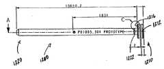
도 12a 및 12b에는 골수내고정못의 삽입을 위해 뼈 내에 초기 개구부를 형성하기 위해서 도 4a 내지 4c의 보호 슬리브(30)와 함께 사용될 수 있는 와이어 가이드 슬리브(400)가 도시된다. 대안적으로, 상기 슬리브(400)(30)는 나선형 칼날 또는 헬리컬 칼날을 골절된 대퇴부 뼈머리에 삽입하여 상기 헤드를 결합된 대퇴부 축에 연결하는데 사용될 수 있다. 미리 천공된 큰 뼈구멍이 이러한 고정 장치를 수용하기 위해 필요할 수 있으며(예를 들어 대략 8mm 내지 대략 17mm), 따라서 상기 보호 슬리브는 뼈 안에 구멍을 뚫기 위해서 큰 드릴 비트(500)(도 13 참조)를 수용하고 안내하기 위해 사용될 수 있다. 상기 와이어 가이드 슬리브(400)는 상기 슬리브(400)(30)를 고정될 뼛조각에 정렬시키기 위해서 가이드 와이어(600)(도 14 참조)와 맞물리기 위해 사용될 수 있다. 상기 가이드 와이어(600)는 하나 이상의 뼛조각에 미리 삽입되어 상기 슬리브(400)(30)를 정밀하게 정렬함으로써 상기 천공된 뼈구멍이 외과의가 원하는 정밀한 궤적을 갖게 할 수 있다. 따라서 준비된 뼈구멍은 설치된 고정 장치가 골절된 뼛조각이 가장 잘 붙는 방식으로 뼈 부분을 맞물리게 할 수 있다.12A and 12B show a
상기 와이어 가이드 슬리브(400)는 도 3a 내지 3e와 관련하여 설명된 드릴 슬리브(20)의 특성 중 일부 또는 전부(예를 들어, 테이퍼진 말단 단부(401), 인접 플랜지 구성요소(402), 일반적으로 원통형인 몸체부(403), 색깔 코딩 등)를 구비할 수 있다. 상기 와이어 가이드 슬리브(400)는 또한 상기 와이어 가이드 슬리브(400)를 보호 슬리브(30)에 축방향으로 잠정적으로 잠그기 위해서 도 3a 내지 3e와 관련하여 설명된 잠금 구조의 일부를 포함할 수도 있다. 예시적인 실시예에서, 상기 와이어 가이드 슬리브(400)는 드릴 슬리브(20)(도 3c 참조)의 원주방향 융기부(2000)와 관련하여 설명된 특징 전부를 갖는 원주방향 융기부(404)를 구비하며, 또한 상기 드릴 슬리브(20)(도 3a 참조)의 슬롯(2050)(2060)에 관련하여 설명된 모든 특성을 갖는 길이방향 슬롯(406)(407)을 구비한다. 더욱이, 상기 와이어 가이드 슬리브(400)는 상기 가이드 와이어(600)를 동축방향으로 수용하도록 크기가 설정되고 구성된 말단 내부 표면(405)을 가질 수 있다. 예시적인 실시예에서, 상기 말단 내부 표면은 대략 3.3mm의 내부 지름 "wgid"을 가질 수 있으며, 이는 표준 3.0mm의 가이드 와이어를 수용할 수 있다. 상기 와이어 가이드 슬리브(400)의 외부 표면 지름 "wgod"는 상기 보호 슬리브(30)의 길이방향 구멍(336) 내에 미끄럼 가능하게 수용될 수 있도록 대략 4mm 내지 대략 17mm가 될 수 있다. 따라서, 상기 와이어 가이드 슬리브(400)는 상기 보호 슬리브(30) 내에 수용될 수 있으며 상기 조립된 슬리브는 따라서 상기 가이드 와이어(600)를 수용할 수 있다. 지시된 치수는 단지 예시를 위한 것이며 더 크거나 더 작은 다른 크기가 또한 고려될 수 있음을 유의해야 한다.The
골수내고정못이 삽입될 수 있는 대퇴부 내에 개구부를 형성하기 위해 상기 보호 슬리브(30)/와이어 가이드 슬리브(400)를 결합하여 사용하기 위해서, 외과의는 먼저 환자의 피부에 뼈의 깊이로 절개부를 만들 수 있다. 상기 보호 슬리브(30), 가이드 슬리브(400) 및 투관침(10)은 도 1과 관련하여 미리 설명된 것처럼 함께 안착될 수 있으며 상기 절개부를 통해서 뼈로 아래 방향으로 삽입될 수 있다. 상기 투관침(10)은 이후 제거될 수 있으며 가이드 와이어가 상기 와이어 가이드 슬리브(400) 내의 삽입관(405)을 통해서 삽입되어 X선 또는 투시관찰 하에 뼈 안으로 진입된다. 상기 가이드 와이어(600)는 외과의가 상기 가이드 와이어(600)를 뼈에 긍정적으로 맞물리게 할 수 있는 나사선 또는 드릴링 첨단부(602)를 가질 수 있다. 일단 상기 가이드 와이어가 적절하게 자리를 잡으면, 상기 와이어 가이드 슬리브(400)는 이후 플랜지(402)를 반경방향으로 가압하여 상기 잠금 구조를 해제함으로써 상기 보호 슬리브(30)로부터 맞물림이 해제될 수 있으며, 상기 가이드 와이어(600)의 자유단(604)으로부터 미끄러질 수 있다. 삽입관(502)을 구비한 드릴(500)은 상기 가이드 와이어(14)의 자유단(604) 위에 놓여 상기 보호 슬리브(30)의 구멍(336) 내로 삽입될 수 있다. 상기 드릴(500)은 상기 첨단(504)이 뼈와 접촉할 때까지 상기 보호 슬리브(30)를 통해 진입될 수 있으며, 이후 회전되어 뼈 안에 원하는 구멍을 뚫을 수 있다. 일단 뼈구멍이 형성되면, 상기 드릴(500)과 보호 슬리브(30)는 상기 절개부로부터 제거될 수 있다. 상기 가이드 와이어(600)는 제거될 수 있거나, 순차적인 공정의 일부로 사용하기 위해 그 자리에 남겨질 수 있다.In order to use the
헬리컬 칼날을 설치하기 위해 상기 보호 슬리브(30)/와이어 가이드 슬리 브(400)를 결합하여 사용하기 위해서, 외과의는 구멍을 뚫은 후에 보호 슬리브(30)와 와이어 가이드(600)를 제거하는 대신에 외과의가 두 구성요소를 그 자리에 두고 단지 드릴 비트(500)만을 제거하는 것 외에는 앞서 설명한 것과 동일한 단계를 수행할 수 있다. 이후, 캐뉼러형 헬리컬 칼날 또는 나선형 칼날은 상기 와이어 가이드의 자유단(604) 위로 미끄러져서 보호 슬리브(30)의 구멍(336) 내로 삽입될 수 있다. 캐눌러형 삽입도구는 상기 와이어 가이드(600) 위로 헬리컬 또는 나선형 칼날을 따르게 할 수 있으며, 뼈 내의 구멍으로 상기 칼날을 삽입하는데 사용될 수 있다.In order to use the
상기 보호 슬리브(30), 드릴 슬리브(20), 와이어 가이드 슬리브(400), 투관침(10) 및 다른 상술한 기구의 일부 또는 전체는 조임쇠의 피부를 통한 배치를 수행하는 외과 공정 중에 사용하기 위한 외과정형 키트의 일부로서 제공될 수 있다. 따라서, 상기 키트는 하나 또는 그 이상의 장치를 포함할 수 있으며, 각각의 장치는 서로 다른 나사 크기에 상응하는 크기를 갖는 투관침, 드릴 슬리브 및 보호 슬리브를 포함할 수 있다. 마찬가지로, 상기 키트가 와이어 가이드 슬리브(400)를 포함하는 경우, 투관침과 보호 슬리브와 마찬가지로 와이어 가이드 슬리브도 서로 다른 나사 또는 나선형/헬리컬 칼날 크기에 상응하는 크기를 가질 수 있다.Some or all of the
골수내고정못을 가지고 사용하기 위한 예시적인 실시예에서, 상기 키트는 각각 3.2mm, 4.0mm 및 5.0mm의 나사 크기에 상응하는 크기를 가진 세 개의 분리 장치를 포함할 수 있다. 다른 장치 크기가 원하는 대로 제공될 수 있다.In an exemplary embodiment for use with intramedullary nails, the kit may include three separation devices having sizes corresponding to screw sizes of 3.2 mm, 4.0 mm and 5.0 mm, respectively. Other device sizes can be provided as desired.
상기 투관침(10), 드릴 슬리브(20), 와이어 가이드 슬리브(400) 및 보호 슬 리브(30)는 스테인리스 스틸, 티타늄, 폴리머 또는 임의의 다른 적절한 물질로 제조될 수 있다. 일실시예에서, 상기 투관침, 드릴 슬리브 및 보호 슬리브는 마틴시틱(martinsitic) 스테인리스 스틸로 제조된다.The
상기 투관침(10), 드릴 슬리브(20), 와이어 가이드 슬리브(400) 및 보호 슬리브(30)는 또한 UHMWPE(Ultra High Molecular Weight Polyethylene), PEEK(Poly-Ether-Ether-Ketone), 압출 탄소섬유 또는 다른 그러한 물질과 같은 방사선 투과성 물질 또는 부분적인 방사선 투과성 물질로 제조될 수 있다. 상기 시스템의 구성요소의 일부 또는 전부는 또한 일회용일 수 있다.The
본 발명이 골수내고정못 시스템으로 이용하는 것에 관련하여 설명되었지만, 본 발명이 본 플레이트, 봉, 못 등과 같은 안정화 장치가 뼈에 적용되는 임의의 외과정형 응용에 적용될 수 있음을 이해할 것이다. 따라서, 본 발명은 소형 플레이트가 머리얼굴뼈대에 적용되고 나사 크기가 1.0mm만큼 작을 수 있는 턱얼굴 시술에 응용될 수 있다. 마찬가지로, 본 발명은 나선형 칼날, 헬리컬 칼날의 설치를 위해, 또는 골수내고정못을 위한 삽입 위치의 개방을 돕기 위해 사용되는 17mm까지의 드릴을 수용하는 대형 치수의 응용에 사용될 수 있다.Although the present invention has been described in connection with use as an intramedullary nailing system, it will be appreciated that the present invention can be applied to any surgical orthopedic application where bone stabilization devices such as bone plates, rods, nails, and the like are applied to the bone. Therefore, the present invention can be applied to the jaw face treatment where a small plate is applied to the head frame and the screw size can be as small as 1.0 mm. Likewise, the present invention can be used for applications of large dimensions to accommodate drills up to 17 mm used for the installation of helical blades, helical blades, or to help open the insertion position for intramedullary nails.
Claims (47)
Translated fromKoreanApplications Claiming Priority (3)
| Application Number | Priority Date | Filing Date | Title |
|---|---|---|---|
| US10/849,714US7033363B2 (en) | 2004-05-19 | 2004-05-19 | Snap-lock for drill sleeve |
| US10/849.714 | 2004-05-19 | ||
| PCT/US2005/017394WO2005112793A1 (en) | 2004-05-19 | 2005-05-17 | Snap-lock for drill sleeve |
Publications (2)
| Publication Number | Publication Date |
|---|---|
| KR20070023756A KR20070023756A (en) | 2007-02-28 |
| KR101176152B1true KR101176152B1 (en) | 2012-08-23 |
Family
ID=35376206
Family Applications (1)
| Application Number | Title | Priority Date | Filing Date |
|---|---|---|---|
| KR1020067026802AExpired - Fee RelatedKR101176152B1 (en) | 2004-05-19 | 2005-05-17 | Snap-lock for drill sleeve |
Country Status (13)
| Country | Link |
|---|---|
| US (3) | US7033363B2 (en) |
| EP (2) | EP1750597B1 (en) |
| JP (1) | JP4726902B2 (en) |
| KR (1) | KR101176152B1 (en) |
| CN (1) | CN100473364C (en) |
| AT (1) | ATE493078T1 (en) |
| AU (1) | AU2005244927B2 (en) |
| BR (1) | BRPI0511243B8 (en) |
| CA (1) | CA2567396C (en) |
| DE (1) | DE602005025624D1 (en) |
| NZ (1) | NZ551912A (en) |
| WO (1) | WO2005112793A1 (en) |
| ZA (1) | ZA200610160B (en) |
Families Citing this family (111)
| Publication number | Priority date | Publication date | Assignee | Title |
|---|---|---|---|---|
| US20080243191A1 (en)* | 2001-10-18 | 2008-10-02 | Fx Devices, Llc | Adjustable bone plate fixation system and metho |
| US20080147126A1 (en)* | 2001-10-18 | 2008-06-19 | Fxdevices, Llc | System and method for a cap used in the fixation of bone fractures |
| US20100312292A1 (en)* | 2001-10-18 | 2010-12-09 | Orthoip, Llc | Lagwire system and method for the fixation of bone fractures |
| US20090131991A1 (en)* | 2001-10-18 | 2009-05-21 | Kishore Tipirneni | System and method for the fixation of bone fractures |
| US20080243132A1 (en)* | 2001-10-18 | 2008-10-02 | Fx Devices, Llc | Tensioning system and method for the fixation of bone fractures |
| US6736819B2 (en) | 2001-10-18 | 2004-05-18 | Kishore Tipirneni | System and method for fixation of bone fractures |
| US20090131936A1 (en)* | 2001-10-18 | 2009-05-21 | Kishore Tipirneni | System and method for the fixation of bone fractures |
| US8679167B2 (en)* | 2001-10-18 | 2014-03-25 | Orthoip, Llc | System and method for a cap used in the fixation of bone fractures |
| US20100268285A1 (en)* | 2001-10-18 | 2010-10-21 | Orthoip, Llc | Bone screw system and method for the fixation of bone fractures |
| US8828067B2 (en)* | 2001-10-18 | 2014-09-09 | Orthoip, Llc | Bone screw system and method |
| US20090048606A1 (en)* | 2001-10-18 | 2009-02-19 | Fxdevices Llc | Guide system and method for the fixation of bone fractures |
| US8702768B2 (en)* | 2001-10-18 | 2014-04-22 | Orthoip, Llc | Cannulated bone screw system and method |
| US9060809B2 (en) | 2001-10-18 | 2015-06-23 | Orthoip, Llc | Lagwire system and method for the fixation of bone fractures |
| US7648509B2 (en) | 2003-03-10 | 2010-01-19 | Ilion Medical Llc | Sacroiliac joint immobilization |
| US7033363B2 (en) | 2004-05-19 | 2006-04-25 | Sean Powell | Snap-lock for drill sleeve |
| WO2006039636A2 (en)* | 2004-10-01 | 2006-04-13 | Simmons Edward D | Screw sleeve made of polyetheretherketone (peek) |
| US8043297B2 (en)* | 2004-11-03 | 2011-10-25 | Synthes Usa, Llc | Aiming arm for bone plates |
| US8961516B2 (en) | 2005-05-18 | 2015-02-24 | Sonoma Orthopedic Products, Inc. | Straight intramedullary fracture fixation devices and methods |
| US9060820B2 (en) | 2005-05-18 | 2015-06-23 | Sonoma Orthopedic Products, Inc. | Segmented intramedullary fracture fixation devices and methods |
| US20060264951A1 (en) | 2005-05-18 | 2006-11-23 | Nelson Charles L | Minimally Invasive Actuable Bone Fixation Devices Having a Retractable Interdigitation Process |
| WO2007011755A2 (en)* | 2005-07-14 | 2007-01-25 | Globus Medical, Inc. | Vertebral marker devices and installation methods |
| US20070038034A1 (en)* | 2005-08-15 | 2007-02-15 | Sweeney Thomas M Ii | Systems and methods for performing percutaneous surgery |
| US7727240B1 (en) | 2006-02-15 | 2010-06-01 | Blake Benton | Method and system for securing an intramedullary nail |
| US20080132900A1 (en)* | 2006-11-13 | 2008-06-05 | Stryker Trauma Gmbh | Drill alignment assembly for a bone plate using tissue protection sleeves that are fixed in the bone plate |
| WO2008064346A2 (en) | 2006-11-22 | 2008-05-29 | Sonoma Orthopedic Products, Inc. | Fracture fixation device, tools and methods |
| US8469963B2 (en)* | 2007-03-05 | 2013-06-25 | Mazor Robotics Ltd. | Bone drilling cannula |
| US20080243135A1 (en)* | 2007-03-30 | 2008-10-02 | Robinson Randolph C | Driver-Fixator System, Method, and Apparatus |
| DE202007007322U1 (en)* | 2007-05-23 | 2008-10-02 | Baumgart, Rainer, Prof. Dr.med., Dipl.-Ing. | Set of instruments for the minimally invasive preparation of a bone nailing |
| US20090005787A1 (en)* | 2007-06-28 | 2009-01-01 | Angela Crall | Device and system for implanting polyaxial bone fasteners |
| ATE482732T1 (en)* | 2007-07-12 | 2010-10-15 | Hoffmann La Roche | FEEDING DEVICE FOR A DEVICE FOR ADMINISTRATION OF A PRODUCT |
| US8496665B2 (en)* | 2008-02-13 | 2013-07-30 | Biomet C.V. | Drill sleeve |
| US8740912B2 (en) | 2008-02-27 | 2014-06-03 | Ilion Medical Llc | Tools for performing less invasive orthopedic joint procedures |
| US8152807B2 (en) | 2008-03-31 | 2012-04-10 | Olecranail Llc | Intramedullary device assembly and associated method |
| JP2011523889A (en) | 2008-06-10 | 2011-08-25 | ソノマ・オーソペディック・プロダクツ・インコーポレーテッド | Device, tool and method for fixing fractures |
| EP3649969A1 (en) | 2008-06-26 | 2020-05-13 | Smart Medical Devices, Inc. | Depth controllable and measurable medical driver devices |
| AU2009266422A1 (en)* | 2008-07-02 | 2010-01-07 | A.H. Beeley Pty Ltd | Apparatus and method of laparoscopic port site suture |
| JP5138501B2 (en)* | 2008-08-11 | 2013-02-06 | 株式会社マキタ | Brush cutter with removable battery pack |
| JP5130147B2 (en)* | 2008-08-11 | 2013-01-30 | 株式会社マキタ | Brush cutter with versatile operation rod |
| JP2012504027A (en) | 2008-09-26 | 2012-02-16 | ソノマ・オーソペディック・プロダクツ・インコーポレーテッド | Bone fixation device, tool and method |
| ES2423032T3 (en) | 2008-12-01 | 2013-09-17 | Straumann Holding Ag | Fixing pin |
| US9039414B2 (en)* | 2009-02-06 | 2015-05-26 | Scott E. Bulloch | Drill guide pin, shank, cannulated drill bit, and driver for creating a hole in a bone |
| CN101862211B (en)* | 2009-04-14 | 2012-07-25 | 上海交通大学医学院附属第九人民医院 | Temporal-mandibular joint disc suturing fixation apparatus |
| US20100274298A1 (en)* | 2009-04-22 | 2010-10-28 | Schiff David C M | Casper pin apparatus and method of use |
| IT1395479B1 (en)* | 2009-05-18 | 2012-09-21 | Scaglia | SURGICAL DEVICE |
| US8216237B2 (en)* | 2009-06-04 | 2012-07-10 | Edwards Scott G | Intramedullary device assembly and associated method |
| JP5666607B2 (en)* | 2009-10-15 | 2015-02-12 | シンセス ゲゼルシャフト ミット ベシュレンクテル ハフツングSynthes Gmbh | Protective sleeve holding device |
| US8894654B2 (en) | 2010-03-31 | 2014-11-25 | Smart Medical Devices, Inc. | Depth controllable and measurable medical driver devices and methods of use |
| US8523873B2 (en)* | 2010-04-08 | 2013-09-03 | Warsaw Orthopedic, Inc. | Neural-monitoring enabled sleeves for surgical instruments |
| CN101822560A (en)* | 2010-04-28 | 2010-09-08 | 常州华森医疗器械有限公司 | Perforating device matched with intramedullary nail |
| CA2804624A1 (en) | 2010-07-23 | 2012-01-26 | Synthes Usa, Llc | Protection sleeve holding mechanism |
| JP5797898B2 (en)* | 2010-12-28 | 2015-10-21 | タキロン株式会社 | Bone tap jig |
| TWI503098B (en)* | 2011-01-31 | 2015-10-11 | Surgical clamps | |
| US10980586B2 (en)* | 2011-03-14 | 2021-04-20 | DePuy Synthes Products, Inc. | Driver device with anti-rotation feature |
| CN102835996B (en)* | 2011-06-23 | 2015-08-26 | 厦门大博颖精医疗器械有限公司 | Lockpin type central nail device |
| US9788844B2 (en) | 2011-12-16 | 2017-10-17 | Medos International Sarl | Methods and systems for attaching tissue to bone |
| EP2797521B1 (en) | 2011-12-29 | 2015-12-09 | Synthes GmbH | Suprapatellar insertion system |
| ES2656974T3 (en)* | 2012-01-19 | 2018-03-01 | Stryker European Holdings I, Llc | Cuff for suprarrotulian surgery |
| US20150164567A1 (en)* | 2012-01-23 | 2015-06-18 | Universitat Zurich | Surgical tool system |
| US20130253544A1 (en)* | 2012-03-20 | 2013-09-26 | S. Charles Marshall, Jr. | System, method, and apparatus for an anterior portal guide for partial thickness rotator cuff repair |
| US10624710B2 (en) | 2012-06-21 | 2020-04-21 | Globus Medical, Inc. | System and method for measuring depth of instrumentation |
| US11864745B2 (en) | 2012-06-21 | 2024-01-09 | Globus Medical, Inc. | Surgical robotic system with retractor |
| US11253327B2 (en) | 2012-06-21 | 2022-02-22 | Globus Medical, Inc. | Systems and methods for automatically changing an end-effector on a surgical robot |
| US12133699B2 (en) | 2012-06-21 | 2024-11-05 | Globus Medical, Inc. | System and method for surgical tool insertion using multiaxis force and moment feedback |
| US11974822B2 (en) | 2012-06-21 | 2024-05-07 | Globus Medical Inc. | Method for a surveillance marker in robotic-assisted surgery |
| US10799298B2 (en) | 2012-06-21 | 2020-10-13 | Globus Medical Inc. | Robotic fluoroscopic navigation |
| US12004905B2 (en) | 2012-06-21 | 2024-06-11 | Globus Medical, Inc. | Medical imaging systems using robotic actuators and related methods |
| US11399900B2 (en) | 2012-06-21 | 2022-08-02 | Globus Medical, Inc. | Robotic systems providing co-registration using natural fiducials and related methods |
| US11857266B2 (en) | 2012-06-21 | 2024-01-02 | Globus Medical, Inc. | System for a surveillance marker in robotic-assisted surgery |
| US11793570B2 (en) | 2012-06-21 | 2023-10-24 | Globus Medical Inc. | Surgical robotic automation with tracking markers |
| US11786324B2 (en) | 2012-06-21 | 2023-10-17 | Globus Medical, Inc. | Surgical robotic automation with tracking markers |
| US10758315B2 (en) | 2012-06-21 | 2020-09-01 | Globus Medical Inc. | Method and system for improving 2D-3D registration convergence |
| US11896446B2 (en) | 2012-06-21 | 2024-02-13 | Globus Medical, Inc | Surgical robotic automation with tracking markers |
| US11298196B2 (en) | 2012-06-21 | 2022-04-12 | Globus Medical Inc. | Surgical robotic automation with tracking markers and controlled tool advancement |
| US11864839B2 (en) | 2012-06-21 | 2024-01-09 | Globus Medical Inc. | Methods of adjusting a virtual implant and related surgical navigation systems |
| US11317971B2 (en) | 2012-06-21 | 2022-05-03 | Globus Medical, Inc. | Systems and methods related to robotic guidance in surgery |
| US11963755B2 (en) | 2012-06-21 | 2024-04-23 | Globus Medical Inc. | Apparatus for recording probe movement |
| US11857149B2 (en) | 2012-06-21 | 2024-01-02 | Globus Medical, Inc. | Surgical robotic systems with target trajectory deviation monitoring and related methods |
| US11589771B2 (en) | 2012-06-21 | 2023-02-28 | Globus Medical Inc. | Method for recording probe movement and determining an extent of matter removed |
| US10874466B2 (en) | 2012-06-21 | 2020-12-29 | Globus Medical, Inc. | System and method for surgical tool insertion using multiaxis force and moment feedback |
| US11045267B2 (en) | 2012-06-21 | 2021-06-29 | Globus Medical, Inc. | Surgical robotic automation with tracking markers |
| US9572589B2 (en) | 2012-07-10 | 2017-02-21 | Stryker European Holdings I, Llc | Drill guide |
| US9295488B2 (en) | 2012-08-09 | 2016-03-29 | Wilson T. Asfora | Joint fusion |
| EP3158952B1 (en)* | 2012-09-14 | 2019-10-23 | Synthes GmbH | Multihole drill sleeve with protection sleeve |
| CN103815959A (en)* | 2012-11-16 | 2014-05-28 | 上海底特精密紧固件股份有限公司 | Bone screw |
| JP5289626B1 (en)* | 2013-01-29 | 2013-09-11 | 順 岡田 | Intramedullary nail target device |
| CN103989512B (en)* | 2013-03-01 | 2018-02-09 | 中山大学 | Portable fracture external fixator |
| DE102013017140B4 (en)* | 2013-10-16 | 2019-05-02 | Rose Plastic Ag | Flexible protective cap for holding shafts with different diameters |
| US20170042591A9 (en)* | 2013-12-12 | 2017-02-16 | Extremity Designs, Llc | Intramedullary anchor-screw fracture fixation |
| US9770278B2 (en) | 2014-01-17 | 2017-09-26 | Arthrex, Inc. | Dual tip guide wire |
| US9814499B2 (en) | 2014-09-30 | 2017-11-14 | Arthrex, Inc. | Intramedullary fracture fixation devices and methods |
| WO2016100158A1 (en) | 2014-12-15 | 2016-06-23 | Smith & Nephew, Inc. | Active fracture compression implants |
| CN104706414B (en)* | 2015-03-30 | 2016-09-28 | 蔡鸿敏 | The entry point of a kind of sacroiliac screw guide pin maintains and direction adjusts instrument |
| US10925592B2 (en) | 2016-01-19 | 2021-02-23 | K2M, Inc. | Tissue dilation system and methods of use |
| US11883217B2 (en) | 2016-02-03 | 2024-01-30 | Globus Medical, Inc. | Portable medical imaging system and method |
| WO2017139674A1 (en) | 2016-02-12 | 2017-08-17 | Smart Medical Devices, Inc. | Driving devices and methods for determining material strength in real-time |
| US10702302B2 (en)* | 2016-05-17 | 2020-07-07 | Covidien Lp | Adapter assembly including a removable trocar assembly |
| CN105832378B (en)* | 2016-06-12 | 2018-07-13 | 贵州梓锐科技有限公司 | Abrasion drill for orthopedic operation |
| US11179144B2 (en)* | 2016-08-29 | 2021-11-23 | Life Spine, Inc. | Minimally invasive surgical system, apparatus and method |
| WO2018063329A1 (en)* | 2016-09-30 | 2018-04-05 | Wright Medical Technology, Inc. | Targeting guide and method for an implant |
| EP3318213B1 (en)* | 2016-11-04 | 2022-10-12 | Globus Medical, Inc | System for measuring depth of instrumentation |
| USD859483S1 (en) | 2016-12-06 | 2019-09-10 | Milwaukee Electric Tool Corporation | Drill bit |
| CN111031946A (en)* | 2017-08-09 | 2020-04-17 | 爱尔康公司 | Self-illuminating microsurgical intubation device |
| US12318122B2 (en)* | 2017-09-13 | 2025-06-03 | Globus Medical, Inc. | Bone stabilization systems |
| US10744671B2 (en) | 2018-03-21 | 2020-08-18 | Milwaukee Electric Tool Corporation | Auger |
| US11058437B2 (en) | 2018-03-29 | 2021-07-13 | Zimmer Biomet Spine, Inc. | Systems and methods for pedicle screw implantation using flexible drill bit |
| WO2019200000A1 (en)* | 2018-04-10 | 2019-10-17 | Texas Scottish Rite Hospital For Children | Improved dynamization device for orthopedic fixation device |
| CN109567883B (en)* | 2018-05-25 | 2024-05-14 | 宁波慈北医疗器械有限公司 | Jaw tractor with self-locking function |
| US11490942B2 (en)* | 2019-11-05 | 2022-11-08 | DePuy Synthes Products, Inc. | Device and system for facilitating insertion of a bone treatment device |
| US20240164795A1 (en)* | 2022-11-22 | 2024-05-23 | Metal Industries Research & Development Centre | Surgical Instrument |
| JP7510481B2 (en)* | 2022-11-28 | 2024-07-03 | 財團法人金屬工業研究發展中心 | Surgical instruments |
| CN118845142B (en)* | 2024-09-25 | 2025-02-28 | 浙江德康医疗器械有限公司 | Intramedullary nail lock hole positioning device and intramedullary nail aiming system |
Citations (2)
| Publication number | Priority date | Publication date | Assignee | Title |
|---|---|---|---|---|
| US5112337A (en) | 1991-02-05 | 1992-05-12 | Depuy Du Pont Orthopaedics | Variable angle, selective length tibial drill guide |
| US5755721A (en) | 1996-03-13 | 1998-05-26 | Synthes | Plate holding drill guide and trocar and method of holding a plate |
Family Cites Families (78)
| Publication number | Priority date | Publication date | Assignee | Title |
|---|---|---|---|---|
| US1685785A (en)* | 1924-10-30 | 1928-10-02 | C F Heinkel | Lock means |
| US2424485A (en)* | 1944-07-03 | 1947-07-22 | Thomas W Maskell | Adjustable jig bushing |
| US3108500A (en)* | 1961-12-11 | 1963-10-29 | Henry H Merriman | Insert bushing |
| US3765034A (en)* | 1971-02-12 | 1973-10-16 | F Johnston | Femoral hip prosthesis with positioning and drill guide assembly |
| US3892232A (en)* | 1973-09-24 | 1975-07-01 | Alonzo J Neufeld | Method and apparatus for performing percutaneous bone surgery |
| SE439429B (en)* | 1982-09-29 | 1985-06-17 | Nils Rydell | HELP TOOLS FOR TELESCOPIC NIKES FOR ORTHOPEDIC USE |
| US4549538A (en)* | 1982-11-12 | 1985-10-29 | Zimmer, Inc. | Pin inserter sheath |
| US4522201A (en)* | 1983-04-14 | 1985-06-11 | Tongue John R | Orthopedic surgery drill guide apparatus |
| US4708540A (en)* | 1985-05-13 | 1987-11-24 | Cbc Industries, Inc. | Wire lock liner |
| DE3518496A1 (en) | 1985-05-23 | 1986-11-27 | Stefan 7790 Meßkirch Henselmann | Method of drilling a hole in a workpiece and guide sleeve for carrying out the method |
| FR2588495B1 (en)* | 1985-10-16 | 1987-12-11 | Aerospatiale | FIXING SOCKET ASSEMBLY FOR MACHINING UNIT AND MACHINING UNIT SUITABLE FOR COOPERATING WITH SUCH SOCKET |
| US4911153A (en)* | 1988-02-04 | 1990-03-27 | Biomet, Inc. | Orthopedic surgical instrument |
| US4862883A (en)* | 1988-04-21 | 1989-09-05 | Yosef Freeland | Interlocking intramedullary nail |
| EP0703757B1 (en)* | 1988-06-13 | 2003-08-27 | Karlin Technology, Inc. | Apparatus for inserting spinal implants |
| US5484437A (en)* | 1988-06-13 | 1996-01-16 | Michelson; Gary K. | Apparatus and method of inserting spinal implants |
| US4969781A (en)* | 1989-04-07 | 1990-11-13 | The B. F. Goodrich Company | Blind fastener hand tool |
| US5139500A (en)* | 1989-05-08 | 1992-08-18 | Schwartz Nathan H | Bone attachment system |
| US4936170A (en)* | 1989-07-28 | 1990-06-26 | Zumeta Roberto G | Color coding system |
| US5129906A (en)* | 1989-09-08 | 1992-07-14 | Linvatec Corporation | Bioabsorbable tack for joining bodily tissue and in vivo method and apparatus for deploying same |
| US5139520A (en)* | 1990-01-31 | 1992-08-18 | American Cyanamid Company | Method for acl reconstruction |
| US5047034A (en)* | 1990-05-29 | 1991-09-10 | Ace Orthopedic Manufacturing | Intramedullary rod screw guide |
| GB9014817D0 (en)* | 1990-07-04 | 1990-08-22 | Mehdian Seyed M H | Improvements in or relating to apparatus for use in the treatment of spinal disorders |
| US5743916A (en)* | 1990-07-13 | 1998-04-28 | Human Factors Industrial Design, Inc. | Drill guide with removable ferrules |
| US6254604B1 (en)* | 1990-07-16 | 2001-07-03 | Arthrotek, Inc. | Tibial guide |
| US6019767A (en)* | 1990-07-16 | 2000-02-01 | Arthrotek | Tibial guide |
| US5232454A (en)* | 1990-08-01 | 1993-08-03 | Smiths Industries Medical Systems, Inc. | Safety needle container |
| US5163940A (en)* | 1991-03-04 | 1992-11-17 | American Cyanamid Company | Surgical drill guide for tibia |
| DE9115200U1 (en)* | 1991-12-07 | 1992-02-13 | Howmedica GmbH, 2314 Schönkirchen | Locking nail for the treatment of fractures of the long bones |
| US5478341A (en)* | 1991-12-23 | 1995-12-26 | Zimmer, Inc. | Ratchet lock for an intramedullary nail locking bolt |
| US5154720A (en)* | 1992-02-19 | 1992-10-13 | Linvatec Corporation | Surgical drill guide |
| SE470177B (en)* | 1992-03-23 | 1993-11-29 | Radi Medical Systems | Device for punching in hard tissue and puncture needle |
| CA2155422C (en) | 1993-02-10 | 2005-07-12 | Stephen D. Kuslich | Spinal stabilization surgical method |
| US5575794A (en)* | 1993-02-12 | 1996-11-19 | Walus; Richard L. | Tool for implanting a fiducial marker |
| ATE263511T1 (en)* | 1993-06-10 | 2004-04-15 | Karlin Technology Inc | PROTECTIVE DEVICE WITH TWO PASSAGES FOR SURGERY OF THE INTERVERBEL SPACE |
| US5403322A (en)* | 1993-07-08 | 1995-04-04 | Smith & Nephew Richards Inc. | Drill guide and method for avoiding intramedullary nails in the placement of bone pins |
| US5458602A (en)* | 1994-01-11 | 1995-10-17 | Mitek Surgical Products, Inc. | Surgical drill guide |
| US5474561A (en)* | 1994-02-01 | 1995-12-12 | Yao; Meei-Huei | All positional and universal guiding device for interlocking intramedullary nail |
| IT1268313B1 (en)* | 1994-07-28 | 1997-02-27 | Orthofix Srl | MECHANICAL EQUIPMENT FOR CENTERING BLIND HOLES FOR BONE SCREWS OF INTRAMIDOLLAR NAILS |
| US5601550A (en)* | 1994-10-25 | 1997-02-11 | Esser; Rene D. | Pelvic pin guide system for insertion of pins into iliac bone |
| US6245072B1 (en)* | 1995-03-27 | 2001-06-12 | Sdgi Holdings, Inc. | Methods and instruments for interbody fusion |
| US6206922B1 (en)* | 1995-03-27 | 2001-03-27 | Sdgi Holdings, Inc. | Methods and instruments for interbody fusion |
| US5613971A (en)* | 1995-08-11 | 1997-03-25 | Depuy Inc. | Ratcheting tibial and femoral guide |
| US5847971A (en)* | 1996-01-05 | 1998-12-08 | Steelcase Incorporated | 3-D spatial GUI querying and manipulating an RDMS for order-entry applications |
| DE19780707C2 (en)* | 1996-03-22 | 2002-09-12 | Sdgi Holdings Inc | Percutaneous surgery device |
| US5948000A (en)* | 1996-10-03 | 1999-09-07 | United States Surgical Corporation | System for suture anchor placement |
| US5766179A (en)* | 1997-03-05 | 1998-06-16 | Orthofix S.R.L. | Mechanical system for blind nail-hole alignment of bone screws |
| US5904685A (en)* | 1997-04-11 | 1999-05-18 | Stryker Corporation | Screw sheath |
| US5851207A (en)* | 1997-07-01 | 1998-12-22 | Synthes (U.S.A.) | Freely separable surgical drill guide and plate |
| US5968050A (en)* | 1997-12-05 | 1999-10-19 | Smith & Nephew, Inc. | Positioning a tibial tunnel |
| US6428541B1 (en)* | 1998-04-09 | 2002-08-06 | Sdgi Holdings, Inc. | Method and instrumentation for vertebral interbody fusion |
| US6206885B1 (en)* | 1998-04-14 | 2001-03-27 | Fathali Ghahremani | Catheter guide and drill guide apparatus and method for perpendicular insertion into a cranium orifice |
| US7033367B2 (en)* | 1998-04-14 | 2006-04-25 | Neurodynamics, Inc. | Slotted catheter guide for perpendicular insertion into a cranium orifice |
| US5951561A (en)* | 1998-06-30 | 1999-09-14 | Smith & Nephew, Inc. | Minimally invasive intramedullary nail insertion instruments and method |
| US6129729A (en)* | 1998-11-11 | 2000-10-10 | Snyder; Samuel J. | Apparatus and method for targeting and/or installing fasteners into an intramedullary nail |
| ATE464847T1 (en)* | 1999-01-25 | 2010-05-15 | Warsaw Orthopedic Inc | INSTRUMENT FOR CREATION OF AN INTERVERBEL SPACE FOR ACCOMMODATION OF AN IMPLANT |
| US6743234B2 (en)* | 1999-02-04 | 2004-06-01 | Sdgi Holdings, Inc. | Methods and instrumentation for vertebral interbody fusion |
| AU761818C (en)* | 1999-02-04 | 2004-05-27 | Warsaw Orthopedic, Inc. | Methods and instrumentation for vertebral interbody fusion |
| US6648895B2 (en)* | 2000-02-04 | 2003-11-18 | Sdgi Holdings, Inc. | Methods and instrumentation for vertebral interbody fusion |
| US6325393B1 (en)* | 1999-10-01 | 2001-12-04 | Tsai-Ching Chen | Chuck device for tools |
| US7081122B1 (en)* | 1999-10-19 | 2006-07-25 | Kyphon Inc. | Hand-held instruments that access interior body regions |
| US6629976B1 (en)* | 1999-11-01 | 2003-10-07 | Sulzer Orthopedics, Ltd. | Radius marrow nail |
| US6287313B1 (en)* | 1999-11-23 | 2001-09-11 | Sdgi Holdings, Inc. | Screw delivery system and method |
| US6210415B1 (en)* | 2000-02-18 | 2001-04-03 | Lab Engineering & Manufacturing, Inc. | Surgical drill guide |
| US6656189B1 (en)* | 2000-05-25 | 2003-12-02 | Synthes (Usa) | Radiolucent aiming guide |
| US6443956B1 (en)* | 2000-09-22 | 2002-09-03 | Mekanika, Inc. | Vertebral drill bit and inserter |
| US6355045B1 (en)* | 2000-12-28 | 2002-03-12 | Depuy Orthopaedics, Inc. | Method and apparatus for surgically preparing a tibia for implantation of a prosthetic implant component which has an offset stem |
| US6451023B1 (en)* | 2001-01-25 | 2002-09-17 | Linvatec Corporation | Guide bushing for coring reamer, storage package for reamer assembly, and method of use |
| US6929606B2 (en)* | 2001-01-29 | 2005-08-16 | Depuy Spine, Inc. | Retractor and method for spinal pedicle screw placement |
| US6517546B2 (en)* | 2001-03-13 | 2003-02-11 | Gregory R. Whittaker | Method and apparatus for fixing a graft in a bone tunnel |
| US6575974B2 (en)* | 2001-07-26 | 2003-06-10 | Yechiel Gotfried | Surgical device and method for connection of fractured bones |
| JP4301944B2 (en) | 2001-08-31 | 2009-07-22 | ウォーソー・オーソペディック・インコーポレーテッド | Intervertebral body fusion method and instrument |
| US20030069581A1 (en)* | 2001-10-04 | 2003-04-10 | Stinson David T. | Universal intramedullary nails, systems and methods of use thereof |
| US7175633B2 (en) | 2001-10-17 | 2007-02-13 | Synthes (Usa) | Orthopedic implant insertion instruments |
| US6835197B2 (en) | 2001-10-17 | 2004-12-28 | Christoph Andreas Roth | Bone fixation system |
| KR100485896B1 (en)* | 2002-01-17 | 2005-04-29 | 조우신 | Device for inserting screws into an intramedullary nail and method thereof |
| ITBO20020200A1 (en)* | 2002-04-15 | 2003-10-15 | Hit Medica Srl | DEVICE FOR THE POSITIONING OF A SCREW TO BE ASSOCIATED AND AN ENDOMIDULAR NAIL FIXED IN THE FEMORE MEDILLARY CHANNEL |
| US20030204262A1 (en)* | 2002-04-30 | 2003-10-30 | Ferguson Joe William | Quick disconnect orthopaedic trials |
| US7033363B2 (en)* | 2004-05-19 | 2006-04-25 | Sean Powell | Snap-lock for drill sleeve |
- 2004
- 2004-05-19USUS10/849,714patent/US7033363B2/ennot_activeExpired - Lifetime
- 2005
- 2005-05-17AUAU2005244927Apatent/AU2005244927B2/ennot_activeCeased
- 2005-05-17NZNZ551912Apatent/NZ551912A/enunknown
- 2005-05-17ZAZA200610160Apatent/ZA200610160B/enunknown
- 2005-05-17ATAT05751069Tpatent/ATE493078T1/ennot_activeIP Right Cessation
- 2005-05-17KRKR1020067026802Apatent/KR101176152B1/ennot_activeExpired - Fee Related
- 2005-05-17EPEP05751069Apatent/EP1750597B1/ennot_activeExpired - Lifetime
- 2005-05-17DEDE602005025624Tpatent/DE602005025624D1/denot_activeExpired - Lifetime
- 2005-05-17EPEP10189091Apatent/EP2275045B1/ennot_activeExpired - Lifetime
- 2005-05-17BRBRPI0511243Apatent/BRPI0511243B8/ennot_activeIP Right Cessation
- 2005-05-17JPJP2007527409Apatent/JP4726902B2/ennot_activeExpired - Fee Related
- 2005-05-17CACA2567396Apatent/CA2567396C/ennot_activeExpired - Lifetime
- 2005-05-17WOPCT/US2005/017394patent/WO2005112793A1/enactiveApplication Filing
- 2005-05-17CNCNB2005800244664Apatent/CN100473364C/ennot_activeExpired - Fee Related
- 2006
- 2006-04-24USUS11/410,846patent/US8974466B2/enactiveActive
- 2015
- 2015-02-03USUS14/613,139patent/US9480488B2/ennot_activeExpired - Lifetime
Patent Citations (2)
| Publication number | Priority date | Publication date | Assignee | Title |
|---|---|---|---|---|
| US5112337A (en) | 1991-02-05 | 1992-05-12 | Depuy Du Pont Orthopaedics | Variable angle, selective length tibial drill guide |
| US5755721A (en) | 1996-03-13 | 1998-05-26 | Synthes | Plate holding drill guide and trocar and method of holding a plate |
Also Published As
| Publication number | Publication date |
|---|---|
| EP1750597B1 (en) | 2010-12-29 |
| EP1750597A1 (en) | 2007-02-14 |
| EP1750597A4 (en) | 2010-01-13 |
| CN100473364C (en) | 2009-04-01 |
| ATE493078T1 (en) | 2011-01-15 |
| US20050261698A1 (en) | 2005-11-24 |
| US20060190001A1 (en) | 2006-08-24 |
| WO2005112793A1 (en) | 2005-12-01 |
| US9480488B2 (en) | 2016-11-01 |
| BRPI0511243B8 (en) | 2021-06-22 |
| US20150150568A1 (en) | 2015-06-04 |
| EP2275045B1 (en) | 2012-05-16 |
| US7033363B2 (en) | 2006-04-25 |
| EP2275045A1 (en) | 2011-01-19 |
| CA2567396C (en) | 2013-09-10 |
| DE602005025624D1 (en) | 2011-02-10 |
| KR20070023756A (en) | 2007-02-28 |
| AU2005244927A1 (en) | 2005-12-01 |
| ZA200610160B (en) | 2008-06-25 |
| BRPI0511243B1 (en) | 2017-03-21 |
| JP4726902B2 (en) | 2011-07-20 |
| BRPI0511243A (en) | 2007-11-27 |
| JP2007537835A (en) | 2007-12-27 |
| AU2005244927B2 (en) | 2010-06-03 |
| US8974466B2 (en) | 2015-03-10 |
| CN1988852A (en) | 2007-06-27 |
| NZ551912A (en) | 2009-09-25 |
| CA2567396A1 (en) | 2005-12-01 |
Similar Documents
| Publication | Publication Date | Title |
|---|---|---|
| KR101176152B1 (en) | Snap-lock for drill sleeve | |
| US6273892B1 (en) | Fracture fixation system | |
| US8025666B2 (en) | Orthopedic implant insertion instruments | |
| US8152807B2 (en) | Intramedullary device assembly and associated method | |
| WO2010141183A1 (en) | Intramedullary device assembly and associated method | |
| AU2016333413B2 (en) | Endosseous screw assembly and internal fixation system comprising said endosseous screw assembly | |
| EP3150154A1 (en) | Endosseous screw assembly and internal fixation system comprising said endosseous screw assembly | |
| GB2617338A (en) | A fixing mechanism | |
| AU2002340219B2 (en) | Orthopedic implant insertion instruments |
Legal Events
| Date | Code | Title | Description |
|---|---|---|---|
| PA0105 | International application | St.27 status event code:A-0-1-A10-A15-nap-PA0105 | |
| R17-X000 | Change to representative recorded | St.27 status event code:A-3-3-R10-R17-oth-X000 | |
| PG1501 | Laying open of application | St.27 status event code:A-1-1-Q10-Q12-nap-PG1501 | |
| A201 | Request for examination | ||
| E13-X000 | Pre-grant limitation requested | St.27 status event code:A-2-3-E10-E13-lim-X000 | |
| P11-X000 | Amendment of application requested | St.27 status event code:A-2-2-P10-P11-nap-X000 | |
| P13-X000 | Application amended | St.27 status event code:A-2-2-P10-P13-nap-X000 | |
| PA0201 | Request for examination | St.27 status event code:A-1-2-D10-D11-exm-PA0201 | |
| PE0902 | Notice of grounds for rejection | St.27 status event code:A-1-2-D10-D21-exm-PE0902 | |
| T11-X000 | Administrative time limit extension requested | St.27 status event code:U-3-3-T10-T11-oth-X000 | |
| P11-X000 | Amendment of application requested | St.27 status event code:A-2-2-P10-P11-nap-X000 | |
| P13-X000 | Application amended | St.27 status event code:A-2-2-P10-P13-nap-X000 | |
| E701 | Decision to grant or registration of patent right | ||
| PE0701 | Decision of registration | St.27 status event code:A-1-2-D10-D22-exm-PE0701 | |
| GRNT | Written decision to grant | ||
| PR0701 | Registration of establishment | St.27 status event code:A-2-4-F10-F11-exm-PR0701 | |
| PR1002 | Payment of registration fee | St.27 status event code:A-2-2-U10-U12-oth-PR1002 Fee payment year number:1 | |
| PG1601 | Publication of registration | St.27 status event code:A-4-4-Q10-Q13-nap-PG1601 | |
| FPAY | Annual fee payment | Payment date:20150716 Year of fee payment:4 | |
| PR1001 | Payment of annual fee | St.27 status event code:A-4-4-U10-U11-oth-PR1001 Fee payment year number:4 | |
| FPAY | Annual fee payment | Payment date:20160720 Year of fee payment:5 | |
| PR1001 | Payment of annual fee | St.27 status event code:A-4-4-U10-U11-oth-PR1001 Fee payment year number:5 | |
| FPAY | Annual fee payment | Payment date:20170719 Year of fee payment:6 | |
| PR1001 | Payment of annual fee | St.27 status event code:A-4-4-U10-U11-oth-PR1001 Fee payment year number:6 | |
| FPAY | Annual fee payment | Payment date:20180718 Year of fee payment:7 | |
| PR1001 | Payment of annual fee | St.27 status event code:A-4-4-U10-U11-oth-PR1001 Fee payment year number:7 | |
| FPAY | Annual fee payment | Payment date:20190718 Year of fee payment:8 | |
| PR1001 | Payment of annual fee | St.27 status event code:A-4-4-U10-U11-oth-PR1001 Fee payment year number:8 | |
| PR1001 | Payment of annual fee | St.27 status event code:A-4-4-U10-U11-oth-PR1001 Fee payment year number:9 | |
| PR1001 | Payment of annual fee | St.27 status event code:A-4-4-U10-U11-oth-PR1001 Fee payment year number:10 | |
| PR1001 | Payment of annual fee | St.27 status event code:A-4-4-U10-U11-oth-PR1001 Fee payment year number:11 | |
| PC1903 | Unpaid annual fee | St.27 status event code:A-4-4-U10-U13-oth-PC1903 Not in force date:20230817 Payment event data comment text:Termination Category : DEFAULT_OF_REGISTRATION_FEE | |
| PC1903 | Unpaid annual fee | St.27 status event code:N-4-6-H10-H13-oth-PC1903 Ip right cessation event data comment text:Termination Category : DEFAULT_OF_REGISTRATION_FEE Not in force date:20230817 |