KR101173668B1 - method and apparatus for measuring depth of three dimensional object with multiple spatial frequencies - Google Patents
method and apparatus for measuring depth of three dimensional object with multiple spatial frequenciesDownload PDFInfo
- Publication number
- KR101173668B1 KR101173668B1KR1020100008088AKR20100008088AKR101173668B1KR 101173668 B1KR101173668 B1KR 101173668B1KR 1020100008088 AKR1020100008088 AKR 1020100008088AKR 20100008088 AKR20100008088 AKR 20100008088AKR 101173668 B1KR101173668 B1KR 101173668B1
- Authority
- KR
- South Korea
- Prior art keywords
- depth
- projector
- spatial frequency
- dimensional object
- light
- Prior art date
- Legal status (The legal status is an assumption and is not a legal conclusion. Google has not performed a legal analysis and makes no representation as to the accuracy of the status listed.)
- Active
Links
- 238000000034methodMethods0.000titleclaimsabstractdescription40
- 238000003384imaging methodMethods0.000claimsdescription7
- 238000000691measurement methodMethods0.000claimsdescription5
- 238000005259measurementMethods0.000claimsdescription3
- 230000010363phase shiftEffects0.000description11
- 238000010586diagramMethods0.000description8
- 239000000284extractSubstances0.000description3
- 238000004364calculation methodMethods0.000description2
- 238000007796conventional methodMethods0.000description2
- 238000005516engineering processMethods0.000description2
- 238000005286illuminationMethods0.000description2
- 230000003287optical effectEffects0.000description2
- 238000013139quantizationMethods0.000description2
- 230000000694effectsEffects0.000description1
- 238000002474experimental methodMethods0.000description1
- 230000002194synthesizing effectEffects0.000description1
- 239000002699waste materialSubstances0.000description1
Images


Landscapes
- Physics & Mathematics (AREA)
- General Physics & Mathematics (AREA)
- Engineering & Computer Science (AREA)
- Length Measuring Devices By Optical Means (AREA)
- Computer Graphics (AREA)
- Theoretical Computer Science (AREA)
- Computer Vision & Pattern Recognition (AREA)
Abstract
Translated fromKoreanDescription
Translated fromKorean본 발명은 3차원 물체의 깊이를 측정하는 방법에 관한 것으로, 더욱 상세하게 말하자면, 다중 공간 주파수를 이용하여 3차원 물체의 깊이를 측정하는 방법 및 그 장치에 관한 것이다.The present invention relates to a method for measuring the depth of a three-dimensional object, and more particularly, to a method and apparatus for measuring the depth of a three-dimensional object using multiple spatial frequencies.
3차원 물체의 깊이를 측정하는 방법으로는 모아레 기술(Moirㅹ technology)을 이용한 방법이 있다. 모아레 기술이란 격자무늬의 패턴을 다양한 광원을 이용하여 물체의 표면에 투사하여 물체의 표면에 나타난 상이한 굴곡과 형태로 물체 고유의 깊이를 추출하는 방법이다.As a method of measuring the depth of a three-dimensional object, there is a method using Moir technology. Moirre technology is a method of extracting the depth of the object in the form of different bends and shapes appearing on the surface of the object by projecting the pattern of the grid pattern on the surface of the object using a variety of light sources.
그러나 기존의 방법은 실험을 통해 촬영한 영상에서 3차원 물체의 깊이를 추출하는데 있어, 언랩핑(Unwrapping) 알고리즘이라는 부가적인 알고리즘이 필요하다. 구체적으로 3차원 물체의 표면에 투사된 빛의 신호가 삼각함수 형태를 가지는데, 이러한 신호를 깊이 정보를 가지는 신호로 변환하기 위해서는 언랩핑 알고리즘이 필요하다. 그러나 언랩핑 알고리즘은 매우복잡하기 때문에 이를 수행하는데 많은 시간이 요구되고 경우에 따라 오차가 발생하기가 용이하다.However, the conventional method requires an additional algorithm called an unwrapping algorithm in extracting the depth of a 3D object from an image captured through experiments. Specifically, a light signal projected on the surface of a 3D object has a trigonometric function, and an unwrapping algorithm is required to convert the signal into a signal having depth information. However, because the unwrapping algorithm is very complex, it takes a lot of time to perform it and in some cases errors are easy to occur.
또한 기존의 방법은 복수의 불연속적인 물체들의 깊이를 추출하는데 있어서 한계가 있다.In addition, existing methods have limitations in extracting the depth of a plurality of discontinuous objects.
또한 기존의 방법은 투사기의 위치, 디지털 카메라의 위치 및 시야각(view-angle)만을 이용하여 영상으로부터 3차원 물체의 깊이를 추출함으로써, 추출된 물체의 깊이에 오차가 발생하기가 쉽다.In addition, the conventional method extracts the depth of the three-dimensional object from the image using only the position of the projector, the position of the digital camera and the view-angle, so that an error is likely to occur in the depth of the extracted object.
본 발명이 이루고자 하는 기술적 과제는 보다 간단하게 3차원 물체의 깊이를 측정하는 방법 및 그 장치를 제공하는 것이다.The technical problem to be achieved by the present invention is to more simply provide a method and apparatus for measuring the depth of a three-dimensional object.
또한 본 발명이 이루고자 하는 기술적 과제는 다중 공간 주파수 패턴을 이용하여 3차원 물체의 깊이를 보다 간단하면서도 정확하게 측정하기 위한 방법 및 장치를 제공하는 것이다.Another object of the present invention is to provide a method and apparatus for measuring a depth of a three-dimensional object more simply and accurately using a multi-spatial frequency pattern.
또한 본 발명이 이루고자 하는 기술적 과제는 언랩핑 알고리즘을 수행하지 않고도 3차원 물체의 깊이를 보다 간단하면서도 정확하게 측정하기 위한 방법 및 장치를 제공하는 것이다.Another object of the present invention is to provide a method and apparatus for measuring the depth of a three-dimensional object more simply and accurately without performing an unwrapping algorithm.
본 발명의 특징에 따른 깊이 측정 장치는, 3차원 물체의 깊이를 측정하는 장치이며, 상기 3차원 물체로 적어도 2개 이상의 공간 주파수에 따른 패턴을 포함하는 다중 공간 주파수 패턴에 따라 해당하는 광을 투사하는 투사기; 상기 광이 투사되는 3차원 물체의 영상을 촬영하고 그에 해당하는 디자털 영상 신호를 출력하는 촬영부; 및 상기 디지털 영상 신호를 토대로 상기 물체의 깊이를 산출하는 측정부를 포함한다.Depth measuring device according to a feature of the present invention is a device for measuring the depth of a three-dimensional object, and projecting the corresponding light according to a multi-spatial frequency pattern including a pattern according to at least two or more spatial frequencies to the three-dimensional object A projector; A photographing unit which photographs an image of the 3D object on which the light is projected and outputs a digital image signal corresponding thereto; And a measuring unit calculating a depth of the object based on the digital image signal.
또한, 본 발명의 다른 특징에 따른 깊이 측정 방법은, 3차원 물체의 깊이를 측정하는 방법이며, 상기 3차원 물체로 적어도 2개 이상의 공간 주파수에 따른 패턴을 포함하는 다중 공간 주파수 패턴을 생성하는 단계; 투사기를 이용하여, 상기 다중 공간 주파수 패턴을 구성하는 공간 주파수에 따른 패턴을 설정 단계별로 위상을 천이시키면서 해당하는 광을 상기 3차원 물체로 투사하고, 촬영부를 이용하여 광을 투사할 때마다 상기 3차원 물체의 영상을 촬영하는 단계; 및 상기 촬영된 영상으로부터 상기 물체의 깊이를 산출하는 단계를 포함한다.In addition, the depth measuring method according to another aspect of the present invention, a method for measuring the depth of a three-dimensional object, generating a multi-spatial frequency pattern comprising a pattern according to at least two or more spatial frequencies with the three-dimensional object ; Using a projector, the corresponding light is projected onto the three-dimensional object while the phase is shifted in steps of setting the pattern according to the spatial frequency constituting the multi-spatial frequency pattern, and each time the light is projected using the photographing unit, the 3 Photographing an image of a dimensional object; And calculating a depth of the object from the photographed image.
본 발명의 실시 예에 따르면, 3차원 물체의 깊이를 산출하기 위한 부가적인 알고리즘을 수행하지 않고도, 효율적으로 3차원 불연속적 물체의 깊이 측정할 수 있다. 그 결과, 깊이 측정에 따른 오류나 시간적 낭비를 절감할 수 있다.According to an embodiment of the present invention, the depth of a three-dimensional discontinuous object can be efficiently measured without performing an additional algorithm for calculating the depth of the three-dimensional object. As a result, errors and time waste caused by the depth measurement can be reduced.
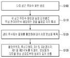
도 1은 본 발명의 실시 예에 따른 다중 주파수를 이용한 깊이 측정 장치의 구조도이다.
도 2는 본 발명의 실시 예에 따른 다중 주파수를 이용한 깊이 측정 방법의 순서도이다.
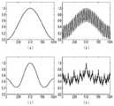
도 3은 본 발명의 실시 예에 따른 공간 주파수 패턴을 나타낸 그래프이다.
도 4는 본 발명의 실시 예에 따른 공간 주파수 패턴의 광을 물체에 투사한 경우의 결과를 나타낸 도면이다.
도 5는 본 발명의 실시 예에 따른 깊이 측정 장치에서, 물체의 깊이 측정을 위한 개념을 나타낸 도이다.1 is a structural diagram of a depth measuring apparatus using multiple frequencies according to an embodiment of the present invention.
2 is a flowchart illustrating a depth measuring method using multiple frequencies according to an exemplary embodiment of the present invention.
3 is a graph showing a spatial frequency pattern according to an embodiment of the present invention.
4 is a diagram illustrating a result of projecting light having a spatial frequency pattern onto an object according to an exemplary embodiment of the present invention.
5 is a diagram illustrating a concept for measuring a depth of an object in a depth measuring apparatus according to an exemplary embodiment of the present disclosure.
아래에서는 첨부한 도면을 참고로 하여 본 발명의 실시 예에 대하여 본 발명이 속하는 기술 분야에서 통상의 지식을 가진 자가 용이하게 실시할 수 있도록 상세히 설명한다. 그러나 본 발명은 여러 가지 상이한 형태로 구현될 수 있으며 여기에서 설명하는 실시 예에 한정되지 않는다. 그리고 도면에서 본 발명을 명확하게 설명하기 위해서 설명과 관계없는 부분은 생략하였으며, 명세서 전체를 통하여 유사한 부분에 대해서는 유사한 도면 부호를 붙였다.Hereinafter, exemplary embodiments of the present invention will be described in detail with reference to the accompanying drawings so that those skilled in the art may easily implement the present invention. As those skilled in the art would realize, the described embodiments may be modified in various different ways, all without departing from the spirit or scope of the present invention. In the drawings, parts irrelevant to the description are omitted in order to clearly describe the present invention, and like reference numerals designate like parts throughout the specification.
명세서 전체에서, 어떤 부분이 어떤 구성요소를 "포함"한다고 할 때, 이는 특별히 반대되는 기재가 없는 한 다른 구성요소를 제외하는 것이 아니라 다른 구성요소를 더 포함할 수 있는 것을 의미한다.Throughout the specification, when a part is said to "include" a certain component, it means that it can further include other components, without excluding other components unless specifically stated otherwise.
이제 첨부한 도면을 참조하여 본 발명의 실시 예에 대하여 설명한다.Embodiments of the present invention will now be described with reference to the accompanying drawings.
도 1은 본 발명의 실시 예에 따른 다중 주파수를 이용한 깊이 측정 장치의 구조도이다.1 is a structural diagram of a depth measuring apparatus using multiple frequencies according to an embodiment of the present invention.
첨부한 도 1에 도시되어 있듯이, 본 발명의 실시 예에 따른 다중 주파수를 이용한 깊이 측정 장치(이하, 설명의 편의를 위하여 깊이 측정 장치라고 명명함)는 투사기(10), 촬영부(20), 및 측정부(30)를 포함한다.As shown in FIG. 1, a depth measuring device (hereinafter, referred to as a depth measuring device for convenience of description) according to an embodiment of the present invention includes a
투사기(10)는 측정하고자 하는 물체로 광을 투사하며 특히, 본 발명의 실시 예에 따른 다중 공간 주파수 패턴을 가지는 광을 물체로 투사한다. 이를 위하여, 본 발명의 실시 예에 따른 투사기(10)는 다중 공간 주파수 패턴을 생성하는 투사 패턴 생성부(11), 다중 공간 주파수 패턴에 따라 광을 생성하여 물체로 투사하는 광 투사부(12)를 포함한다. 다중 공간 주파수 패턴을 생성하는 방법에 대해서는 이후에 구체적으로 설명하기로 한다.The
촬영부(20)는 물체를 촬영하여 그에 해당하는 디지털 영상 신호를 출력하며, 특히 다중 공간 주파수 패턴이 투사된 물체를 촬영하여 그에 해당하는 디지털 영상 신호를 출력한다. 이러한 촬영부(20)는 디지털 카메라일 수 있으며, 물체를 촬영하여 디지털 영상 신호를 생성하는 것은 공지된 기술임으로 여기서는 상세 설명을 생략한다.The photographing
측정부(30)는 디지털 영상 신호로부터 촬영된 물체에 대한 깊이 정보를 추출한다. 깊이 정보를 추출 즉, 깊이 정보를 측정하는 방법에 대해서는 이후에 구체적으로 설명하기로 한다.The
다음에는 이러한 구조를 토대로 본 발명의 실시 예에 따른 다중 주파수를 이용한 3차원 물체의 깊이 측정 방법에 대하여 설명한다.Next, a depth measurement method of a three-dimensional object using multiple frequencies according to an embodiment of the present invention will be described.
본 발명의 실시 예에 따른 깊이 측정 방법은 다중 공간 주파수를 갖는 패턴을 이용한 위상 천이 방식을 토대로 물체로 광을 투사하는, 국부적 조명을 통한 물체 주사 방식을 제공하면서, 이러한 물체 주사 방식을 토대로 획득되는 3차원 물체의 영상을 토대로 해당 물체의 깊이 정보를 추출한다. 즉, 임의의 공간 주파수를 갖는 광을 물체에 투사한 경우, 해당 패턴은 물체 표면에서 깊이에 따라 상이한 굴곡과 형태를 보여주므로, 깊이에 따른 특정 굴곡과 형태를 기하학적 변수를 이용하여 물체의 깊이를 추출한다.Depth measurement method according to an embodiment of the present invention is obtained based on such an object scanning method, while providing an object scanning method with local illumination, to project the light to the object based on a phase shift method using a pattern having a multi-space frequency Depth information of the object is extracted based on the image of the 3D object. In other words, when light having an arbitrary spatial frequency is projected onto an object, the pattern shows different bends and shapes depending on the depth at the surface of the object. Extract.
이러한 본 발명의 실시 예에 따른 깊이 측정 방법은 다중 공간 주파수를 이용한 위상 천이 프로파일로메트리(profilometry)로 명명될 수도 있다.The depth measuring method according to the embodiment of the present invention may be referred to as a phase shift profile by using a multi-spatial frequency.
도 2는 본 발명의 실시 예에 따른 다중 주파수를 이용한 깊이 측정 방법의 순서도이다.2 is a flowchart illustrating a depth measuring method using multiple frequencies according to an exemplary embodiment of the present invention.
본 발명의 실시 예에서는 3차원 물체의 깊이를 추출하기 위해, 촬영부(20)로 촬영되는 도메인(domain) 상에서 임의의 한 지점을, 다른 지점과 구별되도록 설정값 이상의 휘도량을 가지고 다중 공간 주파수 패턴을 가지는 강한 빛으로 투사하고, 그 때의 공간 주파수 조합, 위상 천이(Phase-shifting) 과정과 기하학적 변수를 고려하여 물체의 깊이를 추출한다.According to an embodiment of the present invention, in order to extract the depth of a 3D object, a multi-spatial frequency having a luminance amount equal to or greater than a set value to distinguish an arbitrary point from a domain photographed by the photographing
이를 위하여, 첨부한 도 2에 도시되어 있듯이, 먼저 다중 주파수 패턴을 생성한다(S100).To this end, as shown in FIG. 2, first, a multi-frequency pattern is generated (S100).
본 발명의 실시 예에서 물체를 포함한 도메인의 x축 상의 한 지점을 가장 강한 빛으로 투사하는 임의의 공간 주파수를 갖는 패턴은 다음 수학식 1과 같이 나타낼 수 있다.In an exemplary embodiment of the present invention, a pattern having an arbitrary spatial frequency projecting a point on the x-axis of the domain including the object as the strongest light may be represented by

여기서, s는 도메인의 x축 상에서 함수 값이 가장 큰 위치를 나타낸다. 예를 들어, 도메인이 1부터 1024까지 정의되는 경우, s가 512라는 값을 가질 때, x축 상에서 512가 되는 지점에 꼭지점을 갖는 임펄스 신호를 갖는다. n은 공간 주파수의 계수를 나타낸다.Here, s represents the position where the function value is largest on the x-axis of the domain. For example, if the domain is defined from 1 to 1024, when s has a value of 512, it has an impulse signal having a vertex at a point that becomes 512 on the x-axis. n represents the coefficient of the spatial frequency.
공간 주파수 fn은 다음 수학식 2와 같이 나타낼 수 있다.The spatial frequency fn can be expressed as

패턴의 공간 주파수는 푸리에 전개식(Fourier expansion)의 계수를 이용한 함수로 정의될 수 있다.The spatial frequency of the pattern can be defined as a function using the coefficients of the Fourier expansion.
임의 공간 주파수를 가지는 하나의 패턴은 위상 천이 방식(Phase-shifting method)에 의해 4개의 단계로 각각 위상 천이된다. 예를 들어, 0, π/2, π, 3π/2의 4단계별로 위상이 각각 천이되어, 하나의 공간 주파수에 대하여 총 4개의 패턴이 생성될 수 있다.One pattern with arbitrary spatial frequency is phase shifted in four steps, respectively, by a phase-shifting method. For example, phases are shifted for each of four stages of 0, π / 2, π, and 3π / 2, so that a total of four patterns may be generated for one spatial frequency.
본 발명의 실시 예에서는 위의 수학식 2를 만족하는 공간 주파수별로 설정된 수의 단계를 가지는 위상 천이를 수행하여 복수의 공간 주파수 패턴을 생성한다. 예를 들어,


도 3은 본 발명의 실시 예에 따른 공간 주파수 패턴을 나타낸 그래프이다. 특히 도 3은 본 발명의 실시 예에서 다중 공간 주파수를 갖는 패턴을 이용하는데 있어, 어떤 주파수를 얼마나 많이 합성해야 하는지를 가늠하기 위한 그래프들이다.3 is a graph showing a spatial frequency pattern according to an embodiment of the present invention. In particular, FIG. 3 is a graph for estimating how many frequencies are synthesized in using a pattern having multiple spatial frequencies in an embodiment of the present invention.
본 발명의 실시 예에 따른 다중 공간 주파수 패턴은 공간 주파수를 합성함에 따른 임펄스 신호들로 정의될 수 있다. 예를 들어 한 화면이 촬영부(20)를 이용하여 촬영될 수 있는 영역이라고 볼 때, x축의 중심에 원하는 임펄스 신호를 발생시킨다고 임의 설정할 수 있다. 이 때 임펄스 신호는 물체 표면의 작은 굴곡에도 반응할 수 있도록 설정 각도 이상의 급각도로 발생해야 한다.The multi-spatial frequency pattern according to an embodiment of the present invention may be defined as impulse signals obtained by synthesizing the spatial frequencies. For example, when one screen is regarded as an area that can be photographed using the photographing
도 3의 (a)는 단일 공간 주파수가


도 3의 (c)는 도 3의 (b)와 마찬가지로 두 개의 공간 주파수를 합성했을 경우의 임펄스 신호들을 나타낸 것이지만, 공간 주파수가 다르다. 이 때 공간 주파수는 각각

도 3의 (d)는 9개의 공간 주파수들 합성했을 경우의 임펄스 신호들을 나타낸 것이다. 이 때 합성된 공간 주파수들은


이러한 도 3의 (a) 내지 (d)의 그래프들을 참조하면, 도 3의 (d)와 같이 9개와 같이 다수개의 공간 주파수들을 합성하였을 경우 다른 경우((a) 내지 (c))와 비교하여 가장 급각도의 임펄스 신호들이 발생함을 알 수 있다.Referring to the graphs of (a) to (d) of FIG. 3, when a plurality of spatial frequencies, such as 9, are synthesized as shown in (d) of FIG. 3, compared to other cases ((a) to (c)) It can be seen that the most sharp impulse signals are generated.
그러므로 본 발명의 실시 예에서, 투사기(10)의 투사 패턴 생성부(11)는 수학식 2를 만족하는 공간 주파수들을 적어도 2개 이상을 합성하여 각 공간 주파수들에 대한 패턴들을 포함하는 다중 공간 주파수 패턴을 생성한다.Therefore, in the embodiment of the present invention, the projection
다음, 광 투사부(12)는 투사 패턴 생성부(11)로부터 제공되는 다중 공간 주파수 패턴에 포함되는 각 공간 주파수 패턴에 따른 광 신호들에 해당하는 광 패턴을 물체의 표면에 투사하고(S110), 촬영부(20)는 광 패턴이 투사되는 물체를 촬영한다. 촬영부(20)는 다중 공간 주파수 패턴에 해당하는 광 패턴이 투사되는 물체를 촬영하고, 촬영된 물체에 해당하는 영상의 디지털 영상 신호를 생성한다. 이 때 영상을 디지털 신호로 처리함에 따라, 디지털 방식 특유의 양자화에 의해 임의의 패턴으로 투사한 광에 따른 영상 신호가 획득된다.Next, the
예를 들어, 9개의 공간 주파수를 이용하는 경우, 하나의 공간 주파수별로 위상 천이를 4단계로 각각 수행하면서 위상 천이별 패턴의 광신호를 물체로 투사하고 투사된 물체를 촬영한다. 이러한 투사 및 촬영 과정을 각 공간 주파수별로 위상 천이 단계별로 수행함에 따라, 총 36개의 영상 신호가 획득된다. 이러한 과정을 통하여 획득된 36개의 영상을 통해 일련의 연산과정을 거치면, 하나의 물체에 대하여 세로로 가는 빛을 소정 방향에서부터 스캔하는 것과 같은 효과를 갖게 된다.For example, when nine spatial frequencies are used, phase shifts are performed in four stages for each spatial frequency, and the optical signals of the patterns according to phase shifts are projected onto the object, and the projected object is photographed. As the projection and photographing process is performed in phase shifting steps for each spatial frequency, a total of 36 image signals are obtained. Through a series of calculations through the 36 images obtained through this process, it has the same effect as scanning the vertical light for a single object from a predetermined direction.
보다 구체적으로 설명하면, 3차원 물체의 표면으로 하나의 패턴에 따른 광을 투사하게 되면, 투사된 패턴과 촬영시 이용되는 디지털 카메라의 양자화 특성상 하나의 물체 위에 두 개의 패턴이 겹친 것 같은 효과를 갖게 된다. 이러한 현상은, 물체 표면에 물체의 굴곡과 형태에 따라 임의의 특유 산란 패턴이 생성된다. 특히, 본 발명의 실시 예에 따른 투사기(10)에서 투사되는 패턴은 복수개의 공간 주파수의 합성으로 급각도의 임펄스 신호들을 가지므로, 이 임펄스 신호들이 물체를 포함한 영상 전체를 대상으로 위상 천이 방식에 의해 이동되면서 물체로 주사된다.In more detail, when the light of one pattern is projected onto the surface of the three-dimensional object, the two patterns overlap on one object due to the projected pattern and the quantization characteristics of the digital camera used for photographing. do. This phenomenon generates an arbitrary characteristic scattering pattern depending on the curvature and shape of the object on the surface of the object. In particular, since the pattern projected by the
구체적으로,
이와 같이 하나의 공간 주파수 패턴을 4개의 단계별로 위상 천이시키면서 투사함에 따라, 하나의 공간 주파수 패턴에 대하여 4개의 영상들이 획득된다. 따라서 본 발명의 실시 예에 따라 도 3의 (d)와 같이 9개의 공간 주파수를 사용할 경우 총 36개의 영상들이 획득된다. 이 영상들을 기초로 하여 Fourier expansion의 계수를 적절히 연산하면, 물체의 각 지점에서 그 지점이 가장 밝게 빛나게 될 주파수와 위상 천이 단계의 조합을 찾을 수 있게 되며, 이러한 조합을 역추적하여 그 때의 기하변수를 적용하면 깊이를 추출해낼 수 있다.As described above, one spatial frequency pattern is projected while phase shifting in four stages, so that four images are acquired for one spatial frequency pattern. Accordingly, according to an embodiment of the present invention, when nine spatial frequencies are used as shown in FIG. 3 (d), a total of 36 images are acquired. Properly calculating the coefficient of Fourier expansion based on these images allows us to find the combination of frequency and phase shifting stages at which each point of the object will shine brightest, and trace the combination back to the geometry at that time. Apply a variable to extract the depth.
도 4는 본 발명의 실시 예에 따른 공간 주파수 패턴의 광을 물체에 투사한 경우의 결과를 나타낸 도면이다.4 is a diagram illustrating a result of projecting light having a spatial frequency pattern onto an object according to an exemplary embodiment of the present invention.
도 4의 (a)는 설정 주파수 보다 낮은 공간 주파수를 가지는 패턴을 물체에 투사했을 경우를 나타낸 도면이며, 도 4의 (b)는 설정 주파수보다 높은 공간 주파수를 가지는 패턴을 물체에 투사했을 경우의 도면이다. 이러한 도 4의 (a) 및 (b)를 참조하면, 물체의 깊이에 따라 패턴의 굴곡과 형태가 상이하게 나타남을 알 수 있다.4A is a diagram illustrating a case in which a pattern having a spatial frequency lower than a set frequency is projected onto an object, and FIG. 4B is a case of projecting a pattern having a spatial frequency higher than a set frequency to an object. Drawing. Referring to FIGS. 4A and 4B, it can be seen that the curvature and shape of the pattern are different depending on the depth of the object.
또한 도 4의 (c)는 본 발명의 실시 예에 따른 다중 공간 주파수를 이용한 패턴으로 국부적 조명을 만들어 물체에 주사한 경우를 나타낸 도면이고, 도 4의 (d)는 본 발명의 실시 예에 따른 다중 공간 주파수 패턴을 투사기를 이용하여 투사한 경우, 물체 표면상에 투사된 광의 강도를 나타낸 도면이다. 이러한 도 4의 (c) 및 (d)를 참조하면, 좌측 물체가 우측 물체에 비해 전면에 위치되어 있으므로, 좌측 물체 표면상의 광의 강도가 우측 물체의 표면상의 광의 강도보다 큼을 알 수 있다.In addition, Figure 4 (c) is a view showing a case in which the local illumination in a pattern using a multi-spatial frequency in accordance with an embodiment of the present invention to scan the object, Figure 4 (d) is in accordance with an embodiment of the present invention When the multi-spatial frequency pattern is projected using a projector, the diagram shows the intensity of light projected onto the surface of an object. Referring to FIGS. 4C and 4D, since the left object is positioned in front of the right object, the intensity of light on the surface of the left object is greater than the intensity of light on the surface of the right object.
이와 같이 3차원 물체의 표면 굴곡과 표면 형태에 따라 상이한 굴곡과 형태의 패턴이 나타나므로 광의 강도가 서로 다르게 나타난다. 본 발명의 실시 예에서는 촬영부(20)가 투사기(10)로부터 다중 공간 주파수 패턴에 따라 적어도 2개 이상의 공간 주파수들이 위상 천이되면서 해당하는 광이 투사된 상기 3차원 물체의 영상들을 획득하고, 획득한 영상들을 겹쳐서 3차원 물체의 각 부분의 광의 강도가 서로 다르게 나타내는 디지털 영상을 생성한다(S120). 그리고 이러한 디지털 영상에 나타난 광의 강도 차이를 토대로, 본 발명의 실시 예에 따른 기하학적 변수들을 이용하여 물체의 깊이를 계산한다.As such, different curvature and shape patterns appear according to the surface curvature and the surface shape of the 3D object, and thus the light intensity is different. In an embodiment of the present invention, the photographing
도 5는 본 발명의 실시 예에 따른 깊이 측정 장치에서, 물체의 깊이 측정을 위한 개념을 나타낸 도이다.5 is a diagram illustrating a concept for measuring a depth of an object in a depth measuring apparatus according to an exemplary embodiment of the present disclosure.
측정부(30)는 촬영부(20)로부터 획득되는 디지털 영상 신호들과 기하학적 변수들을 토대로 다음과 같이 물체의 깊이를 측정한다(S130).The measuring
본 발명의 실시 예에서는 광 패턴이 점의 형태로 물체에 투사되는 것이 아니라 예를 들어 세로줄 패턴으로 투사됨으로써, 물체에 대한 x, z를 이용하여 해당 물체의 깊이를 측정한다.In an embodiment of the present invention, the light pattern is not projected onto the object in the form of dots, but is projected in a vertical line pattern, for example, to measure the depth of the object using x and z for the object.
먼저, 획득된 영상 신호로부터 획득되는 좌표 x', z'는 다음과 같이 나타낼 수 있다.First, the coordinates x 'and z' obtained from the obtained image signal may be expressed as follows.


여기서, xCCD와 zCCD는 촬영부(20)의 위치를 나타내고, xPRJ 와 zPRJ는 투사기(10)의 위치를 나타낸다.Here, xCCD and zCCD represent positions of the
촬영부(20)와 투사기(10)가 물체에 대하여 수직으로 위치하지 않으므로, 촬영부(20)와 투사기(10)의 시야각이 서로 겹쳐지도록 하기 위해서 물체에 대한 수직 기준선을 설정하고, 수직 기준선에 대한 각 시야각의 경사각을 정의한다. 즉, 수직 기준선에 대한 촬영부의 시야각의 경사각(또는 제1 경사각)을

또한 도메인의 x축 상에서 임의의 한 지점에 투사되는 광의 양이 가장 큰 경우에, 촬영부의 시야각 중 촬영부가 측정한 상기 지점에 대한 각도(또는 제1 각도)를 θDetect 라고 정의하며, 투사기의 시야각 중 투사기가 투사하는 상기 지점에 대한 각도(또는 제2각도)를 θLocal이라고 정의한다.In addition, when the amount of light projected at any one point on the x-axis of the domain is the largest, the angle (or first angle) with respect to the point measured by the imaging unit among the viewing angles of the imaging unit is defined as θDetect , and the viewing angle of the projector angle (or second angle) with respect to the point that the projector and the projection θ of theLocal It is defined as.
본 발명 실시 예에 따른 기하학적 변수들은 xCCD, zCCD, xPRJ, zPRJ, θDetect, θLocal,


이러한 수학식 3 및 4를 토대로, 실제적으로 측정하고자 하는 물체의 위치(x, z)를 구하기 위하여, x'와 z'를 소거하면 다음과 같은 식을 얻을 수 있다.Based on the equations (3) and (4), in order to obtain the position (x, z) of the object to be measured, the following equation can be obtained by canceling x 'and z'.

투사기(10)의 위치에 대해서도 위의 수학식 5와 같이 x', z'를 소거하면 다음과 같은 수학식 6이 획득된다.Also for the position of the

위에 기술된 바와 같이 산출되는 수학식 5 및 수학식 6을 정리하면 다음과 같이, 실제적으로 측정하는 하는 물체의 위치 관련 좌표 x, z를 구할 수 있다.By arranging


측정부(30)는 측정하고자 하는 물체의 위치 (x, z)를 위에 기술된 바와 같이 측정하고, 측정된 물체의 위치를 토대로 z축을 따라 물체의 깊이를 산출한다.The measuring
이러한 본 발명의 실시 예에 따르면, 다중 공간 주파수를 이용한 광 패턴들과 광 패턴들의 위상 이동, 그리고 광 패턴들의 위상 이동에 따라 획득된 영상들로부터 미리 설정된 기하학적 변수를 이용하여 3차원 물체의 깊이를 추출함으로써, 물체의 깊이 산출을 위한 별도의 알고리즘(예를 들어, 언랩핑 알고리즘)이 필요하지 않으므로, 부가적인 연산을 하는데 있어 발생할 수 있는 연산 오류와 시간을 절약할 수 있다. 그 결과, 보다 효율적으로 3차원 물체의 깊이를 추출할 수 있다.According to the exemplary embodiment of the present invention, the depth of the 3D object is determined by using geometric parameters preset from the light patterns using the multi-spatial frequency, the phase shift of the light patterns, and the images acquired according to the phase shift of the light patterns. By extracting, a separate algorithm (e.g., an unwrapping algorithm) for calculating the depth of the object is not required, thereby saving time and arithmetic errors that may occur in performing additional calculations. As a result, the depth of the three-dimensional object can be extracted more efficiently.
또한 본 발명의 실시 예에 따라 측정된 물체의 위치 좌표 x, z는 절대 좌표이므로, 물체의 불연속적인 표면에 대한 깊이를 용이하게 추출할 수 있다.In addition, since the position coordinates x and z of the object measured according to the embodiment of the present invention are absolute coordinates, the depth of the discontinuous surface of the object may be easily extracted.
본 발명의 실시 예는 이상에서 설명한 장치 및/또는 방법을 통해서만 구현이 되는 것은 아니며, 본 발명의 실시예의 구성에 대응하는 기능을 실현하기 위한 프로그램, 그 프로그램이 기록된 기록 매체 등을 통해 구현될 수도 있으며, 이러한 구현은 앞서 설명한 실시예의 기재로부터 본 발명이 속하는 기술분야의 전문가라면 쉽게 구현할 수 있는 것이다.The embodiments of the present invention are not limited to the above-described apparatuses and / or methods, but may be implemented through a program for realizing functions corresponding to the configuration of the embodiment of the present invention, a recording medium on which the program is recorded And such an embodiment can be easily implemented by those skilled in the art from the description of the embodiments described above.
이상에서 본 발명의 실시 예에 대하여 상세하게 설명하였지만 본 발명의 권리범위는 이에 한정되는 것은 아니고 다음의 청구범위에서 정의하고 있는 본 발명의 기본 개념을 이용한 당업자의 여러 변형 및 개량 형태 또한 본 발명의 권리범위에 속하는 것이다.While the present invention has been particularly shown and described with reference to exemplary embodiments thereof, it is to be understood that the invention is not limited to the disclosed exemplary embodiments, It belongs to the scope of right.
10 : 투사기, 20 : 촬영부, 30 : 측정부10: projector, 20: photographing unit, 30: measuring unit
Claims (10)
Translated fromKorean상기 3차원 물체로 적어도 2개 이상의 공간 주파수에 따른 패턴을 포함하는 다중 공간 주파수 패턴에 따라 해당하는 광을 투사하는 투사기;
상기 광이 투사되는 3차원 물체의 영상을 촬영하고 그에 해당하는 디지털 영상 신호를 출력하는 촬영부;
상기 디지털 영상 신호를 토대로 상기 물체의 깊이를 산출하는 측정부
를 포함하고,
상기 투사기는
상기 다중 공간 주파수 패턴을 구성하는 공간 주파수에 따른 패턴을 설정 단계별로 각각 위상을 천이시키면서 해당하는 광을 상기 3차원 물체로 투사하는, 다중 공간 주파수를 이용한 3차원 물체의 깊이 측정 장치.In a device that measures the depth of a three-dimensional object,
A projector for projecting light corresponding to a multi-spatial frequency pattern including a pattern according to at least two or more spatial frequencies to the three-dimensional object;
A photographing unit which photographs an image of the 3D object on which the light is projected and outputs a digital image signal corresponding thereto;
A measuring unit for calculating the depth of the object based on the digital image signal
Including,
The projector
Apparatus for depth measurement of a three-dimensional object using a multi-spatial frequency to project the corresponding light to the three-dimensional object while the phase shifted each step of setting the pattern according to the spatial frequency constituting the multi-space frequency pattern.
상기 촬영부는
상기 투사기로부터 상기 다중 공간 주파수 패턴에 따라 적어도 2개 이상의 공간 주파수들이 위상 천이되면서 해당하는 광이 투사된 상기 3차원 물체의 영상들을 획득하고,
상기 획득한 영상들을 겹쳐서 상기 3차원 물체의 각 부분의 광의 강도가 다르게 나타난 디지털 영상 신호를 출력하는, 다중 공간 주파수를 이용한 3차원 물체의 깊이 측정 장치.The method of claim 1
The photographing unit
Acquire images of the three-dimensional object from which the corresponding light is projected while at least two or more spatial frequencies are phase shifted from the projector according to the multi-spatial frequency pattern,
And overlapping the obtained images to output a digital image signal in which the intensity of light of each part of the three-dimensional object is different from each other.
상기 측정부는 상기 디지털 영상 신호로부터, 상기 촬영부의 위치, 상기 투사기의 위치, 상기 물체에 대하여 설정된 수직 기준선을 기준으로 경사진 상기 촬영부의 시야각의 경사각, 상기 수직 기준선에 대한 투사기의 시야각의 경사각, 상기 디지털 영상 신호의 설정 지점에 해당하는 상기 촬영부의 각도, 상기 설정 지점에 해당하는 상기 투사기의 각도를 토대로, 상기 물체의 깊이를 산출하는, 다중 공간 주파수를 이용한 3차원 물체의 깊이 측정 장치.The method according to claim 1 or 3
The measurement unit may include the inclination angle of the viewing angle of the photographing unit inclined based on the position of the photographing unit, the position of the projector, the vertical reference line set with respect to the object, the inclination angle of the viewing angle of the projector with respect to the vertical reference line, from the digital image signal. And a depth of the object is calculated based on an angle of the photographing unit corresponding to a set point of a digital image signal and an angle of the projector corresponding to the set point.
상기 설정 지점은 상기 디지털 영상 신호에서 광의 강도가 가장 큰 지점인, 다중 공간 주파수를 이용한 3차원 물체의 깊이 측정 장치.The method of claim 4
And the set point is a point where the intensity of light is the greatest in the digital image signal.
상기 3차원 물체로 적어도 2개 이상의 공간 주파수에 따른 패턴을 포함하는 다중 공간 주파수 패턴을 생성하는 단계;
투사기를 이용하여, 상기 다중 공간 주파수 패턴을 구성하는 공간 주파수에 따른 패턴을 설정 단계별로 각각 위상을 천이시키면서 해당하는 광을 상기 3차원 물체로 투사하고, 촬영부를 이용하여 광을 투사할 때마다 상기 3차원 물체의 영상을 촬영하는 단계; 및
상기 촬영된 영상으로부터 상기 물체의 깊이를 산출하는 단계
를 포함하는 다중 공간 주파수를 이용한 3차원 물체의 깊이 측정 방법.In the method of measuring the depth of a three-dimensional object,
Generating a multi-spatial frequency pattern including the pattern according to at least two or more spatial frequencies with the three-dimensional object;
Using a projector, each phase of the pattern according to the spatial frequency constituting the multi-spatial frequency pattern, the corresponding light is projected to the three-dimensional object while the phase is shifted, and each time the light is projected using the imaging unit Photographing an image of a three-dimensional object; And
Calculating a depth of the object from the captured image
Depth measurement method of the three-dimensional object using a multi-spatial frequency comprising a.
상기 촬영하는 단계는,
상기 투사기로부터 상기 다중 공간 주파수 패턴에 따라 적어도 2개 이상의 공간 주파수들이 위상 천이되면서 해당하는 광이 투사된 상기 3차원 물체의 영상들을 획득하고, 상기 획득한 영상들을 겹쳐서 상기 3차원 물체의 각 부분의 광의 강도가 다르게 나타난 디지털 영상을 획득하는, 다중 공간 주파수를 이용한 3차원 물체의 깊이 측정 방법.The method of claim 6
The photographing step,
Acquire images of the three-dimensional object from which the corresponding light is projected while at least two or more spatial frequencies are phase shifted from the projector according to the multi-spatial frequency pattern, and overlapping the obtained images, Depth measurement method of a three-dimensional object using a multi-spatial frequency to obtain a digital image showing different light intensity.
상기 산출하는 단계는 상기 디지털 영상으로부터, 상기 촬영부의 위치, 상기 투사기의 위치, 상기 물체에 대하여 설정된 수직 기준선을 기준으로 경사진 상기 촬영부의 시야각의 경사각, 상기 수직 기준선에 대한 투사기의 시야각의 경사각, 상기 디지털 영상 신호의 설정 지점에 해당하는 상기 촬영부의 각도, 상기 설정 지점에 해당하는 상기 투사기의 각도를 토대로, 상기 물체의 깊이를 산출하는, 다중 공간 주파수를 이용한 3차원 물체의 깊이 측정 방법.The method of claim 7, wherein
The calculating may include the inclination angle of the viewing angle of the photographing unit inclined based on the position of the photographing unit, the position of the projector, the vertical reference line set with respect to the object, the inclination angle of the viewing angle of the projector with respect to the vertical reference line, from the digital image. And calculating a depth of the object based on an angle of the photographing unit corresponding to a set point of the digital image signal and an angle of the projector corresponding to the set point.
상기 물체의 깊이는 다음의 조건을 토대로 산출되는, 다중 공간 주파수를 이용한 3차원 물체의 깊이 측정 방법.


xCCD, zCCD : 촬영부의 위치
xPRJ, zPRJ : 투사기의 위치


θDetect: 도메인의

θLocal : 도메인의

The depth of the object is calculated based on the following conditions, depth measurement method of a three-dimensional object using a multi-spatial frequency.
xCCD , zCCD : location of image
xPRJ , zPRJ : Projector Position
θDetect : of domain
θLocal : of domain
상기 공간 주파수를 정의하는 함수는 푸리에 전개식의 계수를 이용하는, 다중 공간 주파수를 이용한 3차원 물체의 깊이 측정 방법.
The method according to any one of claims 6 to 9
The method of defining the spatial frequency is a method of measuring the depth of a three-dimensional object using a multi-space frequency, using the coefficient of Fourier expansion.
Priority Applications (1)
| Application Number | Priority Date | Filing Date | Title |
|---|---|---|---|
| KR1020100008088AKR101173668B1 (en) | 2009-10-27 | 2010-01-28 | method and apparatus for measuring depth of three dimensional object with multiple spatial frequencies |
Applications Claiming Priority (3)
| Application Number | Priority Date | Filing Date | Title |
|---|---|---|---|
| KR1020090102498 | 2009-10-27 | ||
| KR20090102498 | 2009-10-27 | ||
| KR1020100008088AKR101173668B1 (en) | 2009-10-27 | 2010-01-28 | method and apparatus for measuring depth of three dimensional object with multiple spatial frequencies |
Publications (2)
| Publication Number | Publication Date |
|---|---|
| KR20110046222A KR20110046222A (en) | 2011-05-04 |
| KR101173668B1true KR101173668B1 (en) | 2012-08-20 |
Family
ID=44241140
Family Applications (1)
| Application Number | Title | Priority Date | Filing Date |
|---|---|---|---|
| KR1020100008088AActiveKR101173668B1 (en) | 2009-10-27 | 2010-01-28 | method and apparatus for measuring depth of three dimensional object with multiple spatial frequencies |
Country Status (1)
| Country | Link |
|---|---|
| KR (1) | KR101173668B1 (en) |
Cited By (1)
| Publication number | Priority date | Publication date | Assignee | Title |
|---|---|---|---|---|
| CN111473745A (en)* | 2020-06-23 | 2020-07-31 | 南京理工大学智能计算成像研究院有限公司 | Light-emitting surface microscopic three-dimensional measurement method based on multi-frequency phase shift scheme |
Families Citing this family (8)
| Publication number | Priority date | Publication date | Assignee | Title |
|---|---|---|---|---|
| KR101434026B1 (en)* | 2012-09-11 | 2014-08-26 | 제주대학교 산학협력단 | Apparatus and method for measuring three-dimension |
| US20140307055A1 (en) | 2013-04-15 | 2014-10-16 | Microsoft Corporation | Intensity-modulated light pattern for active stereo |
| US9158161B2 (en) | 2013-10-01 | 2015-10-13 | Kyungpook National University Industry-Academic Cooperation Foundation | Pattern generator using liquid crystal and method thereof |
| KR102365721B1 (en)* | 2016-01-26 | 2022-02-22 | 한국전자통신연구원 | Apparatus and Method for Generating 3D Face Model using Mobile Device |
| KR101842141B1 (en)* | 2016-05-13 | 2018-03-26 | (주)칼리온 | 3 dimensional scanning apparatus and method therefor |
| KR102317278B1 (en)* | 2017-07-06 | 2021-10-26 | 엘지이노텍 주식회사 | Depth information acquiring method for three dimensional object |
| TWI676781B (en)* | 2018-08-17 | 2019-11-11 | 鑑微科技股份有限公司 | Three-dimensional scanning system |
| CN115096203B (en)* | 2022-06-02 | 2024-06-07 | 深圳市二郎神视觉科技有限公司 | Method for measuring tire tread depth by laser |
- 2010
- 2010-01-28KRKR1020100008088Apatent/KR101173668B1/enactiveActive
Cited By (1)
| Publication number | Priority date | Publication date | Assignee | Title |
|---|---|---|---|---|
| CN111473745A (en)* | 2020-06-23 | 2020-07-31 | 南京理工大学智能计算成像研究院有限公司 | Light-emitting surface microscopic three-dimensional measurement method based on multi-frequency phase shift scheme |
Also Published As
| Publication number | Publication date |
|---|---|
| KR20110046222A (en) | 2011-05-04 |
Similar Documents
| Publication | Publication Date | Title |
|---|---|---|
| KR101173668B1 (en) | method and apparatus for measuring depth of three dimensional object with multiple spatial frequencies | |
| JP5029618B2 (en) | Three-dimensional shape measuring apparatus, method and program by pattern projection method | |
| JP4480488B2 (en) | Measuring device, computer numerical control device, and program | |
| US9322643B2 (en) | Apparatus and method for 3D surface measurement | |
| US20120176478A1 (en) | Forming range maps using periodic illumination patterns | |
| US20120176380A1 (en) | Forming 3d models using periodic illumination patterns | |
| JP6016912B2 (en) | 3D measuring device and 3D measuring method | |
| JP6598673B2 (en) | Data processing apparatus and method | |
| US9441959B2 (en) | Calibration method and shape measuring apparatus | |
| CN104677307B (en) | Measuring method and device combining three-dimensional and two-dimensional shapes | |
| JP6590339B2 (en) | Measuring method, measuring apparatus, measuring program, and computer-readable recording medium recording the measuring program | |
| JP4255865B2 (en) | Non-contact three-dimensional shape measuring method and apparatus | |
| JPWO2017175341A1 (en) | Measuring method, measuring apparatus, measuring program, and computer-readable recording medium recording the measuring program | |
| CN110692084B (en) | Device and machine-readable storage medium for exporting topology information of a scene | |
| JP2016080393A (en) | Three-dimensional measuring device, three-dimensional measuring method, and program | |
| JP5611875B2 (en) | Information display device, information display method, and program | |
| JP2012083233A5 (en) | ||
| JP5822463B2 (en) | Three-dimensional measuring apparatus, three-dimensional measuring method, and program | |
| Marrugo et al. | Fourier transform profilometry in LabVIEW | |
| KR101465996B1 (en) | Method for measurement of high speed 3d shape using selective long period | |
| JP5352997B2 (en) | Three-dimensional shape measuring apparatus, three-dimensional shape measuring method and program | |
| CN112747686A (en) | Three-dimensional shape measuring device | |
| JP6229134B2 (en) | Measuring device | |
| JP6923915B2 (en) | A computer-readable recording medium that records measurement methods, measuring devices, and measurement programs that can simultaneously acquire the three-dimensional shape of a color object and color information. | |
| JP2016008837A (en) | Shape measuring method, shape measuring device, structure manufacturing system, structure manufacturing method, and shape measuring program |
Legal Events
| Date | Code | Title | Description |
|---|---|---|---|
| A201 | Request for examination | ||
| PA0109 | Patent application | Patent event code:PA01091R01D Comment text:Patent Application Patent event date:20100128 | |
| PA0201 | Request for examination | ||
| PG1501 | Laying open of application | ||
| E902 | Notification of reason for refusal | ||
| PE0902 | Notice of grounds for rejection | Comment text:Notification of reason for refusal Patent event date:20110629 Patent event code:PE09021S01D | |
| E902 | Notification of reason for refusal | ||
| PE0902 | Notice of grounds for rejection | Comment text:Notification of reason for refusal Patent event date:20120118 Patent event code:PE09021S01D | |
| E701 | Decision to grant or registration of patent right | ||
| PE0701 | Decision of registration | Patent event code:PE07011S01D Comment text:Decision to Grant Registration Patent event date:20120510 | |
| GRNT | Written decision to grant | ||
| PR0701 | Registration of establishment | Comment text:Registration of Establishment Patent event date:20120807 Patent event code:PR07011E01D | |
| PR1002 | Payment of registration fee | Payment date:20120807 End annual number:3 Start annual number:1 | |
| PG1601 | Publication of registration | ||
| FPAY | Annual fee payment | Payment date:20150730 Year of fee payment:4 | |
| PR1001 | Payment of annual fee | Payment date:20150730 Start annual number:4 End annual number:4 | |
| FPAY | Annual fee payment | Payment date:20160212 Year of fee payment:5 | |
| PR1001 | Payment of annual fee | Payment date:20160212 Start annual number:5 End annual number:5 | |
| FPAY | Annual fee payment | Payment date:20170724 Year of fee payment:6 | |
| PR1001 | Payment of annual fee | Payment date:20170724 Start annual number:6 End annual number:6 | |
| FPAY | Annual fee payment | Payment date:20190902 Year of fee payment:8 | |
| PR1001 | Payment of annual fee | Payment date:20190902 Start annual number:8 End annual number:8 | |
| PR1001 | Payment of annual fee | Payment date:20200820 Start annual number:9 End annual number:9 | |
| PR1001 | Payment of annual fee | Payment date:20211109 Start annual number:10 End annual number:10 | |
| PR1001 | Payment of annual fee | Payment date:20230801 Start annual number:12 End annual number:12 | |
| PR1001 | Payment of annual fee | Payment date:20240724 Start annual number:13 End annual number:13 |