KR101173619B1 - Robot apparatus for endoscopic surgery - Google Patents
Robot apparatus for endoscopic surgeryDownload PDFInfo
- Publication number
- KR101173619B1 KR101173619B1KR1020100039904AKR20100039904AKR101173619B1KR 101173619 B1KR101173619 B1KR 101173619B1KR 1020100039904 AKR1020100039904 AKR 1020100039904AKR 20100039904 AKR20100039904 AKR 20100039904AKR 101173619 B1KR101173619 B1KR 101173619B1
- Authority
- KR
- South Korea
- Prior art keywords
- robot
- robot arm
- internal
- wire
- overtube
- Prior art date
- Legal status (The legal status is an assumption and is not a legal conclusion. Google has not performed a legal analysis and makes no representation as to the accuracy of the status listed.)
- Expired - Fee Related
Links
Images


Classifications
- A—HUMAN NECESSITIES
- A61—MEDICAL OR VETERINARY SCIENCE; HYGIENE
- A61B—DIAGNOSIS; SURGERY; IDENTIFICATION
- A61B34/00—Computer-aided surgery; Manipulators or robots specially adapted for use in surgery
- A61B34/30—Surgical robots
- A61B34/37—Leader-follower robots
- A—HUMAN NECESSITIES
- A61—MEDICAL OR VETERINARY SCIENCE; HYGIENE
- A61B—DIAGNOSIS; SURGERY; IDENTIFICATION
- A61B17/00—Surgical instruments, devices or methods
- A61B17/00234—Surgical instruments, devices or methods for minimally invasive surgery
- A—HUMAN NECESSITIES
- A61—MEDICAL OR VETERINARY SCIENCE; HYGIENE
- A61B—DIAGNOSIS; SURGERY; IDENTIFICATION
- A61B17/00—Surgical instruments, devices or methods
- A61B17/28—Surgical forceps
- A61B17/29—Forceps for use in minimally invasive surgery
- A—HUMAN NECESSITIES
- A61—MEDICAL OR VETERINARY SCIENCE; HYGIENE
- A61B—DIAGNOSIS; SURGERY; IDENTIFICATION
- A61B34/00—Computer-aided surgery; Manipulators or robots specially adapted for use in surgery
- A61B34/30—Surgical robots
- A61B34/35—Surgical robots for telesurgery
- A—HUMAN NECESSITIES
- A61—MEDICAL OR VETERINARY SCIENCE; HYGIENE
- A61B—DIAGNOSIS; SURGERY; IDENTIFICATION
- A61B34/00—Computer-aided surgery; Manipulators or robots specially adapted for use in surgery
- A61B34/70—Manipulators specially adapted for use in surgery
- A61B34/71—Manipulators operated by drive cable mechanisms
- B—PERFORMING OPERATIONS; TRANSPORTING
- B25—HAND TOOLS; PORTABLE POWER-DRIVEN TOOLS; MANIPULATORS
- B25J—MANIPULATORS; CHAMBERS PROVIDED WITH MANIPULATION DEVICES
- B25J18/00—Arms
- B25J18/06—Arms flexible
- A—HUMAN NECESSITIES
- A61—MEDICAL OR VETERINARY SCIENCE; HYGIENE
- A61B—DIAGNOSIS; SURGERY; IDENTIFICATION
- A61B17/00—Surgical instruments, devices or methods
- A61B17/00234—Surgical instruments, devices or methods for minimally invasive surgery
- A61B2017/00292—Surgical instruments, devices or methods for minimally invasive surgery mounted on or guided by flexible, e.g. catheter-like, means
- A61B2017/00296—Surgical instruments, devices or methods for minimally invasive surgery mounted on or guided by flexible, e.g. catheter-like, means mounted on an endoscope
- A—HUMAN NECESSITIES
- A61—MEDICAL OR VETERINARY SCIENCE; HYGIENE
- A61B—DIAGNOSIS; SURGERY; IDENTIFICATION
- A61B17/00—Surgical instruments, devices or methods
- A61B17/28—Surgical forceps
- A61B17/29—Forceps for use in minimally invasive surgery
- A61B2017/2901—Details of shaft
- A61B2017/2908—Multiple segments connected by articulations
- A—HUMAN NECESSITIES
- A61—MEDICAL OR VETERINARY SCIENCE; HYGIENE
- A61B—DIAGNOSIS; SURGERY; IDENTIFICATION
- A61B34/00—Computer-aided surgery; Manipulators or robots specially adapted for use in surgery
- A61B34/30—Surgical robots
- A61B2034/301—Surgical robots for introducing or steering flexible instruments inserted into the body, e.g. catheters or endoscopes
- A—HUMAN NECESSITIES
- A61—MEDICAL OR VETERINARY SCIENCE; HYGIENE
- A61B—DIAGNOSIS; SURGERY; IDENTIFICATION
- A61B34/00—Computer-aided surgery; Manipulators or robots specially adapted for use in surgery
- A61B34/30—Surgical robots
- A61B2034/305—Details of wrist mechanisms at distal ends of robotic arms
Landscapes
- Health & Medical Sciences (AREA)
- Engineering & Computer Science (AREA)
- Life Sciences & Earth Sciences (AREA)
- Surgery (AREA)
- Medical Informatics (AREA)
- Robotics (AREA)
- Biomedical Technology (AREA)
- Heart & Thoracic Surgery (AREA)
- Nuclear Medicine, Radiotherapy & Molecular Imaging (AREA)
- Molecular Biology (AREA)
- Animal Behavior & Ethology (AREA)
- General Health & Medical Sciences (AREA)
- Public Health (AREA)
- Veterinary Medicine (AREA)
- Ophthalmology & Optometry (AREA)
- Mechanical Engineering (AREA)
- Surgical Instruments (AREA)
- Manipulator (AREA)
Abstract
Translated fromKoreanDescription
Translated fromKorean본 발명은 내시경 수술용 로봇장치에 관한 것으로, 보다 상세하게는 링크들로 이루어진 벤딩관절이 구비되며 회전 및 병진운동이 가능하여 4 자유도 이상의 움직임을 구현하는 로봇팔을 이용함으로써 수술부위의 제한된 공간 내에서 시술에 필요한 충분한 움직임을 제공할 뿐만 아니라 효율적인 동력전달구조를 갖는 내시경 수술용 로봇장치에 관한 것이다.
The present invention relates to a robotic device for endoscopic surgery, more specifically, a bending joint consisting of links, and the rotational and translational movement is possible by using a robot arm that implements the movement of more than four degrees of freedom limited space of the surgical site The present invention relates to a robotic device for endoscopy having an efficient power transmission structure as well as providing sufficient movement for a procedure.
종래에는 복강(腹腔) 내의 수술을 위해 배를 절개하고 개방시킨 상태에서 시술하는 개복수술이 일반적이었다. 그러나, 복강경과 소형 수술도구를 이용한 복강경 수술법이 도입되면서 담낭 절제술과 같이 비교적 간단한 수술의 경우 복강경 수술이 일반화되고 있는 추세에 있다. 복강경 수술법은 최소 침습수술(Minimally invasive surgery)의 한 분야로 다수의 작은 절개공(침습점)을 통해 시술함으로써 주위의 장기나 조직의 손상을 최소화하고 입원기간을 대폭 단축시킬 수 있다. 여기서 더 나아가 절개를 하지 않는 비 침습수술(Non-invasive surgery)의 개념이 도입되면서 자연개구부 내시경 수술(Natural orifice transluminal endoscopic surgery)이 다음 세대의 수술법으로 주목받고 있다.Conventionally, a laparotomy is performed with the abdomen open and open for surgery in the abdominal cavity. However, with the introduction of laparoscopic surgery using laparoscopy and small surgical instruments, laparoscopic surgery is becoming more common for relatively simple surgeries such as gallbladder resection. Laparoscopic surgery is a field of minimally invasive surgery that can be performed through many small incisions (minimally invasive points) to minimize damage to surrounding organs and tissues and to significantly shorten hospitalization time. Furthermore, with the introduction of the concept of non-invasive surgery, natural orifice transluminal endoscopic surgery is drawing attention as the next generation.
자연개구부 내시경 수술은 유연성 있는 오버튜브가 자연개구부(입, 항문 또는 질)를 통해 삽입되어 수술부위까지 접근한 후, 오버튜브 내에 구비된 내부로봇을 조종함으로써 필요한 시술을 수행하게 된다. 이때, 내부로봇은 시술에 필요한 충분한 움직임을 구현할 수 있어야 한다. 예를 들면, 통상의 개복수술에 있어 시술자가 두 팔꿈치를 바깥쪽으로 구부린 상태에서 수술부위를 내려다보면서 시술하는 동작을 구현할 수 있어야 한다. 이를 위해, 내부로봇은 1개의 내시경과 2개 이상의 수술도구가 구비되어야 하는 데, 수술부위의 좁은 공간으로 인해 내시경과 수술도구를 적절히 배치하기 어렵고, 위와 같은 수술동작을 충분히 구현하지 못하는 문제점이 있었다. 또한, 수술시 상황에 따라 다른 수술도구가 사용되어야 하는데 공간상의 제약으로 인해 수술도구를 쉽게 교환할 수 없는 문제점이 있었다.In spontaneous opening endoscopic surgery, a flexible overtube is inserted through a natural opening (mouth, anus or vagina) to approach a surgical site, and then a necessary procedure is performed by manipulating an internal robot provided in the overtube. At this time, the internal robot should be able to implement sufficient movement required for the procedure. For example, in a normal open surgery, the operator should be able to implement the operation while looking down at the surgical site with both elbows bent outward. To this end, the internal robot should be provided with one endoscope and two or more surgical tools, and due to the narrow space of the surgical site, it is difficult to properly arrange the endoscope and the surgical tools, and there is a problem in that it is not sufficient to implement the above operation. . In addition, different surgical instruments should be used depending on the situation at the time of surgery, there was a problem that can not easily replace the surgical instruments due to space constraints.
한편, 기존 복강경 시스템의 경우 내부로봇을 침습점을 통해 복강 내부로 직접 인입시킬 수 있어 오버튜브가 필요치 않고, 시술에 필요한 내부로봇의 움직임(4 자유도)을 비교적 용이하게 구현할 수 있다. 그러나, 자연개구부 내시경 수술의 경우 오버튜브가 굴곡된 통로로 삽입되기 때문에 내부로봇이 유연성을 가질 필요가 있다. 그러나, 유연한 샤프트를 이용하여 내부로봇을 제작하는 경우 외부에서 제공하는 내부로봇의 실제적인 최대 자유도는 2 자유도로 제한되어 미세한 수술동작을 구현하기 어려운 문제점이 있었다.On the other hand, in the case of the existing laparoscopic system can directly introduce the internal robot into the abdominal cavity through the invasion point, it does not require an overtube, it is possible to easily implement the movement (4 degrees of freedom) of the internal robot required for the procedure. However, in the case of spherical endoscopy, the internal robot needs to have flexibility because the overtube is inserted into the curved passage. However, when manufacturing an internal robot using a flexible shaft, the actual maximum degree of freedom of the internal robot provided from the outside is limited to two degrees of freedom, which makes it difficult to implement a minute surgical operation.
또한, 상술된 유연성 문제와 상반된 힘의 전달 문제가 있다. 단단한 재질의 샤프트는 외부에서 전달하는 힘을 충분히 전달할 수 있지만 유연성이 부족하고, 이와 반대로 유연 재질의 샤프트는 충분한 힘을 전달할 수 없는 문제점이 있다.
In addition, there is a problem of force transfer that is contrary to the flexibility problem described above. The shaft of a rigid material can sufficiently transmit the force transmitted from the outside, but lacks flexibility, on the contrary, the shaft of the flexible material has a problem in that it cannot transmit sufficient force.
본 발명은 상기와 같은 종래기술의 문제점을 해결하기 위해 제안된 것으로서, 본 발명의 목적은 유연성을 가지는 동시에 외부에서 제공하는 힘을 충분히 전달할 수 있는 효율적인 관절구조를 구비하고, 내시경과 수술도구의 삼각 배치를 통해 수술부위의 제한된 공간 내에서 시술에 필요한 4 자유도 이상의 움직임을 구현할 수 있는 내시경 수술용 로봇장치를 제공하는 것이다.The present invention has been proposed to solve the problems of the prior art as described above, an object of the present invention is to have a flexible joint structure capable of sufficiently transmitting the force provided from the outside while having flexibility, and the triangle of the endoscope and surgical instruments It is to provide an endoscopic surgical robot device that can realize the movement of more than four degrees of freedom required for the procedure within the limited space of the surgical site through the arrangement.
본 발명의 다른 목적은 수술도구를 용이하게 교환할 수 있고, 효율적인 동력전달구조를 갖는 내시경 수술용 로봇장치를 제공하는 것이다.
Another object of the present invention is to provide an endoscopic surgical robot device which can easily exchange surgical instruments and has an efficient power transmission structure.
상기와 같은 본 발명의 목적은,According to an aspect of the present invention,
자연개구부 또는 미소절개부를 통해 수술부위로 접근하는 유연성을 갖는 오버튜브(100); 유연 샤프트(200a)와, 단단하고 링크들로 이루어진 벤딩관절이 구비된 로봇팔(200b)로 구성되어 오버튜브(100) 내에 형성된 복수의 내부로봇(200); 오버튜브(100)의 말단 또는 복수의 내부로봇(200) 중 하나의 말단에 형성된 내시경(300); 내부로봇(200)을 회전운동시키는 회전구동부(400a)와, 내부로봇(200)을 병진운동시키는 병진구동부(400b)로 이루어진 내부로봇 구동수단(400); 로봇팔(200b)을 구동시키는 로봇팔 구동수단(500); 및 로봇팔(200b)의 말단에 형성된 수술도구(600);를 포함하는 것을 특징으로 하는 내시경 수술용 로봇장치에 의하여 달성될 수 있다.Overtube (100) having the flexibility to access the surgical site through the natural opening or micro-incision; A plurality of
그리고, 오버튜브(100)는 복수의 내부채널(110)이 형성되어 내부로봇(200)이 각각 삽입되고, 병진구동부(400b)의 구동에 의해 로봇팔(200b)이 오버튜브(100)로부터 돌출되거나 오버튜브(100)에 인입된다.In addition, the
또한, 유연 샤프트(200a)와 로봇팔(200b)의 링크들 각각에 중공이 형성됨으로써 내부로봇(200)의 길이방향으로 채널이 형성되고, 수술도구(600)가 채널을 통해 삽입 설치된다. 이때, 유연 샤프트(200a)와 상기 로봇팔(200b)은 단단한 재질의 벤딩관절로 이루어지는 것이 바람직하다.In addition, a hollow is formed in each of the links of the
또한, 내부로봇(200)은 한 쌍이 구비되고, 한 쌍의 로봇팔(200b)이 오버튜브(100)의 말단에서 돌출되고, 돌출된 로봇팔(200b)과 삼각 배치를 이루도록 내시경(300)이 오버튜브(100)의 말단에 형성된다.In addition, the
이와 달리, 내부로봇(200)은 한 쌍이 구비되고, 한 쌍의 로봇팔(200b)이 오버튜브(100)의 말단부 양측에서 각각 돌출되고, 돌출된 로봇팔(200b)과 삼각 배치를 이루도록 내시경(300)이 오버튜브(100)의 말단에 형성될 수도 있다.On the contrary, the
또한, 로봇팔(200b)은 유연 샤프트(200a)의 말단과 연결된 팔꿈치 관절부(210)와, 팔꿈치 관절부(210)의 말단과 연결되어 2 자유도를 구현하는 손목 관절부(220)와, 로봇팔 구동수단(500)에 의해 각각 작동되어 팔꿈치 관절부(210)와 손목 관절부(220)를 동시에 벤딩시키는 복수의 제1 와이어(W1)로 이루어진다.In addition, the
또한, 팔꿈치 관절부(210)는 복수의 링크(212, 214)가 구비되어 곡선 또는 각진 형태로 벤딩된다.In addition, the
이와 달리, 팔꿈치 관절부(210)는 유연 샤프트(200a)와 손목 관절부(220)를 연결하는 일체형 유연링크(216)와, 일체형 유연링크(216)를 벤딩시키는 4절 이상의 링크장치(218a, 218b, 218c, 218d, 218e)로 이루어져 1 자유도를 구현할 수 있다.On the contrary, the
또한, 손목 관절부(220)는 팔꿈치 관절부(220)와 연결된 시작링크(222a)와, 수술도구(600)가 설치되는 말단링크(222b)와, 시작링크(222a)와 말단링크(222b) 사이에 서로 접하는 1개 이상의 제1 및 제2 회전링크(222c, 222d)가 구비되고, 그리고 제1 와이어(W1)의 작동에 의해 시작링크(222a)와 제1 및 제2 회전링크(222c, 222d)가 서로 미끌어지면서 회전하는 구조를 갖는다.In addition, the
이와 달리, 손목 관절부(220)는 다수의 연결링크(224a, 224a')와, 연결링크(224a, 224a')들 사이에 설치된 다수의 탄성부재로 구성되고, 제1 와이어(W1)의 작동에 의해 탄성부재가 만곡되는 구조를 가질 수 있다.On the other hand, the
이때, 탄성부재는 원형 단면을 갖는 탄성 봉체(226)이거나, 직사각 단면을 갖는 탄성 플레이트(228)일 수 있다.In this case, the elastic member may be an
또한, 제1 와이어(W1)는 4개가 구비되며, 스틸 와이어 또는 초탄성 니티놀 와이어인 것이 바람직하다.In addition, four first wires W1 are provided, preferably, steel wires or superelastic nitinol wires.
또한, 회전구동부(400a)는 소정 간격으로 이격 설치된 제1 및 제2 지지대(412, 414)와, 제1 원통형 축(432a)이 형성되어 제1 지지대(412)에 설치된 제1 회전바퀴(432)와, 제2 원통형 축(434a)이 형성되어 제2 지지대(414)에 설치된 제2 회전바퀴(434)와, 제1 및 제2 회전바퀴(432, 434)에 양단이 각각 고정된 한 쌍의 슬라이드축(442, 444)과, 제2 회전바퀴(434)를 정,역회전시키는 제1 모터(M1)가 구비되고, 그리고 내부로봇(200)의 유연 샤프트(200a)가 제1 원통형 축(432)에 삽입 고정된다.In addition, the
그리고, 병진구동부(400b)는 한 쌍의 슬라이드축(442, 444)에 직선 안내되는 가동 플레이트(450)와, 모터축에 제3 풀리(P3)가 형성되고, 모터축이 슬라이드축(442, 444)과 평행하도록 가동 플레이트(450)의 일측에 고정설치된 제2 모터(M2)와, 제3 풀리(P3)와 인접하여 가동 플레이트(450)에 고정설치된 제4 풀리(P4)와, 일단이 제1 회전바퀴(432)에 고정되며 제4 풀리(P4), 제3 풀리(P3), 다시 제4 풀리(P4)에 차례로 감긴 뒤 긴장된 상태에서 타단이 제2 회전바퀴(434)에 고정된 제2 와이어(W2)가 구비된다.The
또한, 로봇팔 구동수단(500)은 제1 와이어(W1)를 각각 직진운동시킴으로써 로봇팔(200b)을 구동시키는 복수의 와이어 구동부(502)가 구비된다.In addition, the robot
이때, 와이어 구동부(502)는 제3 모터(M3)와, 제3 모터(M3)에 의해 정,역회전하는 웜(510)과, 웜(510)의 회전력을 전달받는 한 쌍의 웜휠(520)과, 웜휠(520)의 축(522)에 각각 설치되고, 제1 와이어(W1)를 안내하는 안내홈(532)이 외주면에 형성된 한 쌍의 마찰자(530)로 구비된다. 그리고, 마찰자(530) 사이의 간격을 조절하기 위한 조절나사(544)가 구비된다.
In this case, the
이상에서 설명한 바와 같이 본 발명에 따른 내시경 수술용 로봇장치는 내부로봇이 유연 샤프트와, 단단하고 짧은 링크들로 이루어진 로봇팔을 구비함으로써 충분한 유연성을 가짐과 동시에 내부로봇 구동수단 및 로봇팔 구동수단에 의해 발생된 동력이 효과적으로 전달될 수 있다. 또한, 내부로봇은 내부에 형성된 채널을 통해 각종 수술도구을 용이하게 교환할 수 있다.As described above, the endoscope surgical robot apparatus according to the present invention has sufficient flexibility by having an internal robot having a flexible shaft and a robot arm composed of hard and short links, and at the same time the internal robot driving means and the robot arm driving means. The power generated by this can be transmitted effectively. In addition, the internal robot can easily exchange various surgical instruments through the channel formed therein.
그리고, 로봇팔은 와이어에 의해 연결된 팔꿈치 관절부와 손목 관절부로 이루어지고, 로봇팔 구동수단에 의해 구동된다. 이때, 팔꿈치 관절부는 곡선 또는 각진 형태로 벤딩됨으로써 자연스러운 팔꿈치 동작을 구현할 수 있다. 또한, 팔꿈치 관절부는 일체형 유연링크와 4절 이상의 링크장치로 이루어져 추가적인 1 자유도를 구현할 수 있다. 그리고, 손목 관절부는 다수의 회전링크로 구성되거나 연결링크와 탄성부재로 이루어짐으로써 2 자유도의 미세한 벤딩동작을 구현할 수 있다.The robot arm is composed of an elbow joint portion and a wrist joint portion connected by a wire, and is driven by the robot arm driving means. At this time, the elbow joint portion may be bent in a curved or angular form to implement a natural elbow operation. In addition, the elbow joint portion is made of a flexible link and four or more link devices can implement an additional 1 degree of freedom. In addition, the wrist joint part may be composed of a plurality of rotary links or a link link and an elastic member to realize a fine bending motion of two degrees of freedom.
또한, 로봇팔은 내부로봇 구동수단에 의해 회전 및 병진운동이 가능하고, 이로 인해 4 자유도 이상의 움직임을 구현할 수 있다. 이와 같은 로봇팔은 오버튜브의 말단부에서 내시경과 삼각 배치를 이룸으로써 수술부위의 제한된 공간에서 효과적인 시술을 가능케 한다. 예를 들면 수술부위에 대한 절개, 봉합, 레이저 치료 등의 미세한 작업을 수행할 수 있다.In addition, the robot arm can be rotated and translated by the internal robot drive means, thereby enabling the movement of more than four degrees of freedom. Such a robotic arm achieves a triangular arrangement with the endoscope at the distal end of the overtube, thereby enabling an effective procedure in the limited space of the surgical site. For example, microscopic operations such as incisions, sutures, and laser treatments to surgical sites can be performed.
그리고, 본 발명에 따른 내부로봇 구동수단은 병진구동부가 회전구동부의 슬라이드축에서 직선 안내되는 효율적인 구조를 가짐으로써 구동부의 부피를 대폭 줄일 수 있다. 또한, 회전구동부의 제2 회전바퀴에 형성된 원통형 축은 로봇팔 구동수단 및 병진구동부의 모터 배선을 외부로 연장시키기 위한 통로로 활용됨으로써 회전구동부의 동작을 원활하게 할 수 있다.In addition, the internal robot drive means according to the present invention can significantly reduce the volume of the drive by having an efficient structure in which the translation drive is linearly guided on the slide shaft of the rotary drive. In addition, the cylindrical shaft formed on the second rotation wheel of the rotary drive unit can be used as a passage for extending the motor wiring of the robot arm drive unit and the translational drive unit to the outside can facilitate the operation of the rotary drive unit.
또한, 본 발명에 따른 로봇팔 구동수단은 로봇팔의 벤딩동작을 구현하기 위해 일반적으로 사용되는 유연성 있는 와이어와, 이를 감아서 구동시키기 위한 다수의 풀리가 구비되는 복잡한 구조를 채택하지 않는다. 그 대신 한 쌍의 마찰자를 이용하여 와이어를 밀고 당길 수 있는 비교적 간단한 구조가 구비된다. 즉, 초탄성 니티놀 와이어와 같이 비교적 단단한 재질의 와이어를 사용할 수 있기 때문에 로봇팔의 벤딩동작을 보다 정밀하게 제어할 수 있으며 내구성 또한 크게 향상시킬 수 있다.In addition, the robot arm driving means according to the present invention does not adopt a complex structure having a flexible wire that is generally used to implement the bending operation of the robot arm, and a plurality of pulleys for driving the robot arm. Instead, a relatively simple structure is provided that can push and pull the wire using a pair of friction elements. That is, since a wire of a relatively hard material such as superelastic nitinol wire can be used, the bending motion of the robot arm can be more precisely controlled and durability can be greatly improved.
이와 같은 본 발명에 따른 내시경 수술용 로봇장치는 자연개구부 내시경 수술뿐만 아니라 복강경 수술에도 적용이 가능하고, 의료분야 외의 타산업에서도 폭넓게 응용될 수 있다.
The robot device for endoscopic surgery according to the present invention can be applied to laparoscopic surgery as well as endoscopic surgery of the natural opening, it can be widely applied in other industries other than the medical field.
비록 본 발명이 상기에서 언급한 바람직한 실시예와 관련하여 설명되어졌지만, 본 발명의 요지와 범위로부터 벗어남이 없이 다른 다양한 수정 및 변형이 가능한 것은 당업자라면 용이하게 인식할 수 있을 것이며, 이러한 변경 및 수정은 모두 첨부된 특허청구의 범위에 속함은 자명하다.
Although the present invention has been described in connection with the above-mentioned preferred embodiments, it will be readily apparent to those skilled in the art that various other modifications and variations are possible without departing from the spirit and scope of the invention. Are all within the scope of the appended claims.
도 1은 본 발명에 따른 내시경 수술용 로봇장치의 전체적인 구성을 나타내는 개략도.
도 2a는 내시경과 로봇팔의 삼각 배치구조의 일례를 나타내는 도면.
도 2b는 내시경과 로봇팔의 삼각 배치구조의 변형예를 나타내는 도면.
도 2c는 내시경과 로봇팔의 삼각 배치구조의 또 다른 변형예를 나타내는 도면.
도 3a 내지 도 3c는 본 발명에 따른 로봇팔의 손목 관절부를 나타내는 사시도.
도 4a 및 도 4b는 손목 관절부의 변형예를 나타내는 사시도.
도 5는 내부로봇 구동수단을 나타내는 사시도.
도 6은 로봇팔 구동수단의 제1 와이어 구동부를 나타낸 사시도.
도 7은 4개의 제1 와이어 구동부가 조립된 로봇팔 구동수단을 나타내는 사시도.
도 8은 내부로봇 구동수단과 로봇팔 구동수단의 결합상태를 나타내는 사시도.
도 9는 본 발명에 따른 내시경 수술용 로봇장치의 운동 메카니즘을 나타낸 개략도.1 is a schematic view showing the overall configuration of the robot device for endoscopic surgery according to the present invention.
2A is a view showing an example of a triangular arrangement structure of the endoscope and the robot arm.
2B is a view showing a modification of the triangular arrangement structure of the endoscope and the robot arm.
Figure 2c is a view showing another modification of the triangular arrangement of the endoscope and robot arm.
Figure 3a to 3c is a perspective view showing the wrist joint of the robot arm according to the present invention.
4A and 4B are perspective views showing a modification of the wrist joint part.
5 is a perspective view showing an internal robot drive means.
Figure 6 is a perspective view showing a first wire drive of the robot arm drive means.
7 is a perspective view showing a robot arm driving means in which four first wire driving units are assembled;
Figure 8 is a perspective view showing a coupling state of the internal robot drive means and the robot arm drive means.
Figure 9 is a schematic diagram showing the movement mechanism of the robot device for endoscopic surgery according to the present invention.
이하, 본 발명의 바람직한 실시예를 첨부한 도면들을 참조하여 상세히 설명한다. 각 도면의 구성요소들에 참조부호를 부가함에 있어서, 동일한 구성요소들에 대해서는 비록 다른 도면상에 표시되더라도 가능한 한 동일한 부호를 사용한다.Hereinafter, preferred embodiments of the present invention will be described in detail with reference to the accompanying drawings. In adding reference numerals to components of each drawing, the same reference numerals are used for the same components as much as possible even though they are shown in different drawings.
(내시경 수술용 로봇장치의 구성)(Configuration of robot device for endoscopic surgery)
도 1은 본 발명에 따른 내시경 수술용 로봇장치의 전체적인 구성을 나타내는 개략도이다. 본 발명에 따른 내시경 수술용 로봇장치(10)는 오버튜브(100), 내부로봇(200), 내시경(300), 내부로봇 구동수단(400), 로봇팔 구동수단(500) 및 수술도구(600)로 구성된다.Figure 1 is a schematic diagram showing the overall configuration of the robot device for endoscopic surgery according to the present invention. Endoscope
오버튜브(100)는 도 1에 점선으로 표시되어 있다. 오버튜브(100)는 자연개구부(입, 항문, 질) 혹은 미소 절개부위를 통해 수술부위 근처로 접근하는 역할을 한다. 오버튜브(100)는 유연성 있는 관 형태로 약 15 ~ 30mm의 직경을 갖는다. 이와 같은 오버튜브(100)는 단순한 관 형태로 시술자가 수동으로 이동시킬 수 있고, 이와 달리 별도의 이동수단(미도시) 및 구동부(미도시)가 구비되어 조종장치(미도시)로 이동시킬 수 있는 구조를 가질 수 있다.The
내부로봇(200)은 도 1에 도시된 바와 같이 유연 샤프트(200a)와 로봇팔(200b)로 구성되어 복수개가 오버튜브(100)에 삽입설치된다. 이와 달리 내부로봇(200)은 오버튜브(100)의 말단에 고정설치됨으로써 서로 일체를 이룰 수도 있다. 본 실시예에 의하면 내부로봇(200)은 한 쌍이 구비되고, 내부로봇 구동수단(400)에 의하여 도 1에서와 같이 로봇팔(200b)이 오버튜브(100)의 말단으로부터 돌출되거나, 오버튜브(100)에 인입되는 구조를 갖는다. 즉, 로봇팔(200b)이 오버튜브(100)에 인입된 상태에서 자연개구부 혹은 미소절개부를 통해 수술부위 근처로 접근하면 로봇팔(200b)과 수술도구(600)가 돌출되게 된다.The
한편, 내부로봇(200)의 유연 샤프트(200a)와 로봇팔(220b)에는 길이방향으로 채널(미도시)이 형성됨으로써 이를 통해 수술도구(600)가 삽입 설치된다. 즉, 유연 샤프트(200a)는 유연 재질의 일체형 관 형태로 제작되고, 로봇팔(200b)은 중공을 갖는 짧은 링크들로 이루어진 벤딩관절을 구비한다. 이때, 유연 샤프트(200a) 역시 중공을 갖는 다수의 링크가 연결된 벤딩관절 구조를 갖는 것도 가능하다. 또한, 로봇팔(220b) 및 유연 샤프트(200a)의 벤딩관절은 금속, 합성수지, 세라믹 등의 단단한 재질로 제작함으로써 내부로봇 구동수단(400)에서 제공되는 힘을 효율적으로 전달할 수 있다.On the other hand, the flexible shaft (200a) and the robot arm (220b) of the
한편, 로봇팔(220b)의 벤딩관절은 도 2a 내지 도 2c에 도시된 바와 같이 유연 샤프트(200a)의 말단과 연결된 팔꿈치 관절부(210)와, 팔꿈치 관절부(210)의 말단과 연결된 손목 관절부(220)로 구성된다. 이때, 로봇팔 구동수단(500)이 도 6에 도시된 제1 와이어(W1)를 밀거나 당김으로써 팔꿈치 관절부(210)와 손목 관절부(220)가 동시에 벤딩되는 구조를 갖는다. 이에 대한 구체적인 설명은 후술하기로 한다.Meanwhile, the bending joint of the robot arm 220b has an elbow joint 210 connected to the end of the
내시경(300)은 수술부위의 영상을 촬영하기 위한 특수 카메라가 구비된다. 본 실시예에 의하면 내시경(300)은 도 1에 도시된 바와 같이 오버튜브(100)의 말단에 설치된다. 이와 달리 내시경(300)을 로봇팔(200b)의 말단에 설치하여 내부로봇(200)을 이동시키면서 촬영하는 것도 가능하다.
내부로봇 구동수단(400)은 내부로봇(200)을 회전 및 병진운동시키게 된다. 이에 대한 구체적인 구성 및 작동은 후술하기로 한다.The internal robot driving means 400 rotates and translates the
로봇팔 구동수단(500)은 내부로봇 구동수단(400) 내에 설치되어 로봇팔(200b)을 벤딩시키는 역할을 한다. 이에 대한 구체적인 구성 및 작동은 후술하기로 한다.Robot arm driving means 500 is installed in the internal robot driving means 400 serves to bend the robot arm (200b). Detailed configuration and operation thereof will be described later.
수술도구(600)는 시술을 위한 집게, 가위, 레이저장치 등일 수 있다. 이때, 수술도구(600)는 앞서 설명한 바와 같이 내부로봇(200) 내부에 형성된 채널(미도시)을 통해 삽입 설치되는 구조를 갖는다. 즉, 각종 수술도구를 채널(미도시)을 통해 로봇팔(200b)의 말단부에 착탈시킴으로써 수술을 신속하고 효율적으로 수행할 수 있다. 이와 같은 수술도구(600)는 별도의 외부 동력(미도시)에 의해 구동된다. 그리고, 회전 및 병진운동이 가능하도록 구성될 수 있다.
(내시경과 로봇팔의 삼각 배치구조)(Triangular arrangement of endoscope and robot arm)
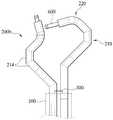
도 2a는 내시경과 로봇팔의 삼각 배치구조의 일례를 나타내는 도면이다. 도 2a에 도시된 바와 같이 내시경(300)은 오버튜브(100)의 말단에 형성된다. 그리고, 한 쌍의 로봇팔(200b)이 오버튜브(100)의 말단에서 돌출됨으로써 내시경(300)과 삼각 배치를 이루게 된다. 한편, 수술도구(600)는 내부로봇(200)의 내부에 형성된 채널을 통해 설치된다.2A is a view showing an example of a triangular arrangement structure of the endoscope and the robot arm. As shown in FIG. 2A, the
로봇팔(200b)의 팔꿈치 관절부(210)는 도 2a에서와 같은 각진 형태의 링크(214)들로 이루어져 있다. 이때, 도 6에 도시된 제1 와이어(W1)를 당기게 되면 팔꿈치 관절부(210)가 내시경(300)을 중심으로 팔꿈치 형태로 벤딩된다. 또한, 도면에는 도시되어 있지 않지만 오버튜브(100)를 통해 이산화탄소와 같은 가스를 수술부위에 주입함으로써 팔꿈치 관절부(210)의 동작을 위한 비교적 넉넉한 공간이 확보될 수 있다. 한편, 도 6의 제1 와이어(W1)를 느슨하게 풀어주면 팔꿈치 관절부(210)가 유연성을 갖게 되어 오버튜브(100)로 인입될 수 있다.The elbow
손목 관절부(220)는 도 2a에서와 같이 짧은 링크들로 이루어져 있다. 손목 관절부(220)는 제1 와이어(W1)의 구동에 의해 2 자유도로 벤딩된다. 손목 관절부(220)에 대한 구체적인 설명은 후술하기로 한다.Wrist joint 220 consists of short links, as in Figure 2a. The wrist joint 220 is bent in two degrees of freedom by the driving of the first wire W1. A detailed description of the wrist joint 220 will be described later.
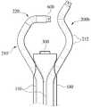
도 2b는 내시경과 로봇팔의 삼각 배치구조의 변형예를 나타내는 도면이다. 도 2b에 도시된 변형예에 따르면, 오버튜브(100) 내부에 2개의 내부채널(110)이 형성되고, 한 쌍의 내부로봇(200)이 각각 삽입 설치된다. 이때, 내부채널(110)의 말단부는 오버튜브(100)의 말단부 양측으로 비스듬하게 형성되어 있다. 따라서, 로봇팔(200b)의 팔꿈치 동작을 보다 용이하게 구현할 수 있다. 이때, 팔꿈치 관절부(210')는 곡선 형태의 링크(212)들로 이루어져 있어서 수술부위의 조직이 손상되는 것을 최소화할 수 있다.2B is a view showing a modification of the triangular arrangement structure of the endoscope and the robot arm. According to a modification illustrated in FIG. 2B, two
도 2c는 내시경과 로봇팔의 삼각 배치구조의 또 다른 변형예를 나타내는 도면이다. 도 2c에 도시된 변형예에 따르면 팔꿈치 관절부(210")는 일체형 유연링크(216)와, 이를 벤딩시키기 위한 4절 이상의 링크장치가 구비된다. 본 실시예에 의하면 링크장치는 5개의 링크(218a, 218b, 218c, 218d, 218e)가 구비되고, 오버튜브(100)의 말단과 함께 6절 링크를 이루게 된다. 본 실시예에 따른 팔꿈치 관절부(210")는 추가적인 1 자유도를 구현할 수 있다. 결국, 로봇팔(200b)은 손목 관절부(220)와 함께 3 자유도의 움직임을 구현할 수 있게 되어 보다 섬세한 작업을 수행할 수 있다.
Figure 2c is a view showing another modification of the triangular arrangement of the endoscope and robot arm. According to the modification shown in Fig. 2c, the elbow
(손목 관절부의 구성)(Composition of Wrist Joint)
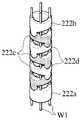
도 3a 내지 도 3c는 본 발명에 따른 로봇팔의 손목 관절부를 나타내는 사시도이다. 손목 관절부(220)는 도 3a 내지 3c에 도시된 바와 같이 시작링크(222a), 말단링크(222b), 교대로 배열된 다수의 제1 및 제2 회전링크(222c, 222d)가 구비되고, 4개의 제1 와이어(W1)가 이들을 관통하여 연결하게 된다. 이때, 손목 관절부(220)의 내부에 형성된 구멍은 수술도구(600)가 삽입되는 채널이 된다. 시작링크(222a)는 팔꿈치 관절부(220)와 연결되고, 소정 형태의 미끄러짐 면이 형성되어 있다. 말단링크(222b)는 제1 와이어(W1)의 일단이 고정되고, 한 쌍의 돌기가 형성되어 있다. 그리고, 제1 회전링크(222c)는 한 쌍의 돌기와 미끄러짐 면의 저부가 대응되게 형성(같은 위치)되어 있으며, 제2 회전링크(222d)는 한 쌍의 돌기와 미끄러짐 면의 저부가 90°위상차로 형성되어 있다. 한편, 제1 와이어(W1)는 여러 가닥의 스틸 와이어를 꼬아 만든 일반적인 스틸 와이어 로프가 사용될 수 있으며, 탄성 변형범위가 큰 1가닥의 초탄성 니티놀(Nitinol) 와이어가 사용될 수 있다.3a to 3c are perspective views showing the wrist joint of the robot arm according to the present invention. Wrist joint 220 is provided with a start link (222a), a distal link (222b), a plurality of alternately arranged first and second rotary links (222c, 222d), as shown in Figure 3a to 3c, 4 First wires W1 penetrate through them. At this time, the hole formed in the inside of the wrist joint 220 becomes a channel into which the
이와 같이 구성된 손목 관절부(220)는 제1 와이어(W1)들의 밀고 당겨진 상태에 따라 시작링크(222a)와 제1 및 제2 회전링크(222c, 222d)들이 서로 미끌어지면서 회전하게 되고, 이로 인해 2 자유도로 벤딩된다. 예를 들면 도 3a에서 좌측의 와이어를 아래로 당기고 우측의 와이어를 위로 밀게 되면, 손목 관절부(220)는 좌측으로 벤딩된다. 한편, 교대로 배열된 제1 및 제2 회전링크(222c, 222d)의 수가 증가할수록(도 3a에서 도 3b로 갈수록) 벤딩관절의 등방성이 커져서 보다 섬세한 벤딩동작을 구현할 수 있다. 아울러, 각 링크들의 구동각이 작아지기 때문에 수술도구(600)를 채널로 삽입하여 구동하기 쉬어진다.The wrist joint 220 configured as described above is rotated while the
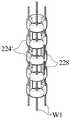
도 4a 및 도 4b는 손목 관절부의 변형예를 나타내는 사시도이다. 도 4a 및 4b에 도시된 변형예에 따르면, 손목 관절부(220')는 다수의 연결링크(224a, 224a')들 사이에 다수의 탄성부재(226, 228)가 규칙적으로 배열되어 지지하는 구조를 갖는다. 이때, 탄성부재는 도 4a에서와 같이 원형 단면을 갖는 탄성 봉체(226)일 수 있고, 도 4b에서와 같이 직사각 단면을 갖는 탄성 플레이트(228)일 수 있다. 본 실시예에 의하면 제1 와이어(W1)들의 밀고 당겨진 상태에 따라 탄성부재(226, 228)들이 직접 휘어지고, 이에 따라 손목 관절부(220')가 2 자유도로 벤딩되는 구조를 갖는다.
4A and 4B are perspective views showing a modification of the wrist joint part. According to the modification illustrated in FIGS. 4A and 4B, the wrist joint 220 ′ has a structure in which a plurality of
(내부로봇 구동수단의 구성)(Configuration of Internal Robot Drive Means)
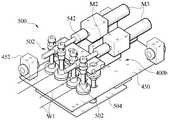
도 5는 본 발명에 따른 내부로봇 구동수단을 나타내는 사시도이다. 내부로봇 구동수단(400)은 도 1에 도시된 내부로봇(200)을 회전 및 병진운동시키기 위한 것으로, 도 5에 도시된 바와 같이 회전구동부(400a)와 병진구동부(400b)로 구성된다.5 is a perspective view showing an internal robot drive means according to the present invention. The internal robot drive means 400 is for rotating and translating the
회전구동부(400a)는 제1 및 제2 지지대(412, 414), 제1 및 제2 회전바퀴(432, 434), 한 쌍의 슬라이드축(442, 444), 그리고 제1 모터(M1)가 구비되어 있다.The
제1 및 제2 지지대(412, 414)는 지지봉(420)의 양단이 각각 고정됨으로써 이격 설치되어 있다.Both ends of the
제1 회전바퀴(432)는 중심에 제1 원통형 축(432a)이 형성되어 제1 지지대(412)에 회전가능하도록 설치되어 있다. 이때, 내부로봇(200)의 유연 샤프트(200a)는 제1 원통형 축(432a)에 삽입 고정되고, 이에 따라 유연 샤프트(200a)는 제1 회전바퀴(432)와 함께 회전하게 된다.A first
제2 회전바퀴(434)는 제2 원통형 축(434a)이 형성되어 제2 지지대(414)에 회전가능하도록 설치되어 있다. 그리고, 제1 및 제2 회전바퀴(432, 434)는 한 쌍으로 각각 구비된 슬라이드축(442, 444)과 지지축(446, 448)에 의해 고정 연결된다.The
제1 모터(M1)는 제2 지지대(414)에 설치되어 제1 및 제2 회전바퀴(432, 434)를 정회전 혹은 역회전시킴으로써 유연 샤프트(200a)를 회전시키게 된다. 이때, 제1 모터(M1)와 제2 회전바퀴(434)는 도 5에 도시된 바와 같이 제1 풀리(P1)와 제2 풀리(P2)가 각각 구비되어 타이밍 벨트로 연결되어 있다.The first motor M1 is installed on the
병진구동부(400b)는 가동 플레이트(450), 제2 모터(M2), 제3 풀리(P3), 제 풀리(P4), 그리고 제2 와이어(W2)가 구비된다.The
가동 플레이트(450)는 도 5에 도시된 바와 같이 유연 샤프트(200a)의 끝단이 고정되어 있다. 그리고, 가동 플레이트(450)의 모서리에는 부시(452)가 형성된 고정홀더(452)가 구비되어 한 쌍의 슬라이드축(442, 444)에 의해 안내될 수 있도록 삽입 설치된다.As shown in FIG. 5, the
제2 모터(M2)는 모터축에 제3 풀리(P3)가 형성되어 있고, 모터축이 슬라이드축(442, 444)과 평행하도록 가동 플레이트(450)의 일측에 설치된다. 그리고, 제4 풀리(P4)는 제3 풀리(P3)와 인접하여 가동 플레이트(450)에 회전가능하게 설치된다.The second motor M2 is provided with a third pulley P3 on the motor shaft, and is installed at one side of the
제2 와이어(W2)는 일단이 제1 회전바퀴(432)에 고정되며 제4 풀리(P4), 제3 풀리(P3), 다시 제4 풀리(P4)에 차례로 감긴 뒤 긴장된 상태에서 타단이 제2 회전바퀴(434)에 고정되어 있다.One end of the second wire W2 is fixed to the
이와 같은 구성을 갖는 병진구동부(400b)는 제2 모터(M2)가 정회전 혹은 역회전함에 따라 가동 플레이트(450)가 슬라이드축(442, 444)을 따라 병진운동하게 되고, 이에 따라 유연 샤프트(200a)가 함께 병진운동하게 된다.In the
한편, 앞서 설명한 제2 회전바퀴(434)의 제2 원통형 축(434a)은 병진구동부(400b)의 제2 모터(M2)와 이후에서 설명될 로봇팔 구동수단(500)의 제3 모터(M3)의 배선을 외부로 연장시키기 위한 통로로 활용된다. 이로 인해 모터(M2, M3) 배선의 꼬임현상을 방지하고, 회전구동부(400a)를 무한대로 회전시킬 수 있다.
On the other hand, the second
(로봇팔 구동수단의 구성)(Configuration of Robot Arm Driving Means)
도 6은 로봇팔 구동수단의 제1 와이어 구동부를 나타낸 사시도이다. 도 6에 도시된 와이어 구동부(502)는 제1 와이어(W1)를 직진 운동시킴으로써 도 1 및 도 2에 도시된 로봇팔(200b)을 구동시키기 위한 것이다.Figure 6 is a perspective view showing a first wire drive of the robot arm drive means. The
본 실시예에 의하면 와이어 구동부(502)는 제3 모터(M3), 웜(510), 한 쌍의 웜휠(520), 한 쌍의 마찰자(530), 고정 플레이트(542) 및 조절나사(544)를 구비하고 있다.According to the present embodiment, the
도 6에서와 같이 고정 플레이트(542)에는 한 쌍의 웜휠축(522)이 설치되어 있고, 웜휠축(522)의 상측과 하측에는 웜휠(520)과 마찰자(530)가 각각 고정 설치되어 있다. 이때, 한 쌍의 마찰자(530)의 외주면에는 제1 와이어(W1)를 안내하는 안내홈(532)이 형성되어 있다. 그리고, 한 쌍의 웜휠(520)을 회전시키기 위한 웜(510)이 설치된다. 이때, 웜(510)은 웜축(512)에 고정되고, 웜축(512)은 커플링(514)에 의해 제3 모터(M3)의 축과 연결되어 있다. 그리고, 한 쌍의 마찰자(530) 사이의 간격을 가변시킴으로써 제1 와이어(W1)와의 마찰력을 조절하기 위한 조절나사(544)가 고정 플레이트(542)에 구비되어 있다.As shown in FIG. 6, a pair of
이와 같은 구성을 갖는 와이어 구동부(502)는 제3 모터(M3)의 회전력이 웜(510)과 웜휠(520)을 거쳐 한 쌍의 마찰자(530)에 전달된다. 그리고, 제3 모터(M3)가 정회전 혹은 역회전함에 따라 제1 와이어(W1)를 밀거나 당길 수 있게 된다.In the
도 7은 4개의 제1 와이어 구동부가 조립된 로봇팔 구동수단을 나타내는 사시도이다. 본 발명에 따른 로봇팔 구동수단(500)은 도 7에서와 같이 4가닥의 제1 와이어(W1)를 각각 직진운동시키기 위하여 4개의 와이어 구동부(502)가 조립된다. 이때, 와이어 구동부(502)는 2개가 조를 이루어 전술한 병진구동부(400b)의 가동 플레이트(450)의 상,하측에 각각 설치된다. 이때, 가동 플레이트(450)의 하부에는 고정 플레이트(542)를 고정하기 위한 지지 플레이트(504)가 설치된다. 이와 같은 와이어 구동부(502)의 조립구조는 로봇팔 구동수단(500)의 부피를 대폭 줄일 수 있다.7 is a perspective view illustrating a robot arm driving means in which four first wire driving units are assembled. As shown in FIG. 7, the robot
도 8은 내부로봇 구동수단과 로봇팔 구동수단의 결합상태를 나타내는 사시도이다. 본 발명에 따른 로봇팔 구동수단(500)은 도 8에서와 같이 병진구동부(400b)에 설치된다. 이때, 가동 플레이트(450)와 지지 플레이트(504)는 각각 한 쌍씩 구비되어 로봇팔 구동수단(500)을 지지하게 된다.
8 is a perspective view illustrating a coupling state between the internal robot driving means and the robot arm driving means. Robot arm driving means 500 according to the present invention is installed in the
(내시경 수술용 로봇장치의 작동)(Operation of Endoscopic Robotic Device)
이하, 도 9를 참조하여 본 발명에 따른 내시경 수술용 로봇장치의 작동에 대하여 설명한다.Hereinafter, the operation of the endoscope surgical robot device according to the present invention with reference to FIG.
도 9는 본 발명에 따른 내시경 수술용 로봇장치의 운동 메카니즘을 나타낸 개략도이다. 본 발명에 따른 내시경 수술용 로봇장치(10)는 시술자가 내시경(300)과 모니터(미도시)를 이용하여 수술부위를 관찰함과 동시에 조종장치(미도시)를 이용하여 내부로봇(200) 및 수술도구(600)를 수술부위로 이동시키고 수술도구(600)를 조작함으로써 필요한 시술을 수행하는 일종의 매니퓰레이터 장치이다.Figure 9 is a schematic diagram showing the movement mechanism of the robot device for endoscopic surgery according to the present invention. The endoscope
본 발명에 따른 내시경 수술용 로봇장치(10)는 도 9에 도시된 바와 같이 내부로봇 구동수단(400)의 회전구동부(400a)는 제1 및 제2 회전바퀴(432, 434)가 모터에 의해 회전하게 되면, 제1 원통형 축(432a)에 삽입고정된 유연 샤프트(200a)가 함께 회전하게 된다. 그리고, 병진구동부(400b)가 회전구동부(400b)의 제1 및 제2 슬라이드축(442, 444)을 따라 직진운동을 하게 되면, 유연 샤프트(200a)도 함께 직진운동을 하게 된다. 결국, 로봇팔(200b)과 수술도구(600)가 구비된 내부로봇(200)은 도 9에 도시된 화살표와 같이 회전 및 병진운동을 하게 되어 2 자유도를 구현할 수 있다.In the endoscope
또한, 병진구동부(400b)에 설치된 로봇팔 구동수단(500)은 제1 와이어(W1)를 밀거나 당김으로써 로봇팔(200b)을 벤딩 구동시켜 2 자유도를 구현할 수 있다. 따라서, 본 발명에 따른 내시경 수술용 로봇장치(10)는 4 자유도의 움직임을 구현할 수 있는 것이다.In addition, the robot arm driving means 500 installed in the
한편, 병진구동부(400a)와 로봇팔 구동수단(500)의 모터 배선이 회전구동부(400)의 제2 회전바퀴(434)에 형성된 제2 원통형 축(434a)을 통해 외부로 연장됨으로써 회전구동부(400)의 원활한 회전을 가능케 한다.On the other hand, the motor wiring of the
그리고, 수술도구(600)가 내부로봇(200)의 내부에 형성된 채널(미도시)을 통해 설치되기 때문에 수술도구의 교환이 채널을 통해 간단하게 이루어질 수 있다.
And, since the
10 : 내시경 수술용 로봇장치
100 : 오버튜브
110 : 내부채널
112, 114 : 로봇팔 돌출공
200 : 내부로봇
200a : 유연 샤프트
200b : 로봇팔
210, 210', 210" : 팔꿈치 관절부
212 : 곡선 링크
214 : 각진 링크
216 : 일체형 유연링크
218a, 218b, 218c, 218d, 218e : 링크
220 : 손목 관절부
222a : 시작링크
222b : 말단링크
222c : 제1 회전링크
222d : 제2 회전링크
224, 224' : 연결링크
226 : 탄성 봉체
228 : 탄성 플레이트
300 : 내시경
400 : 내부로봇 구동수단
400a : 회전구동부
400b : 병진구동부
412 : 제1 지지대
414 : 제2 지지대
420 : 지지봉
432 : 제1 회전바퀴
432a : 제1 원통형 축
434 : 제2 회전바퀴
434a : 제2 원통형 축
442, 444 : 슬라이드축
446, 448 : 지지축
450 : 가동 플레이트
452 : 고정홀더
452a : 부시
500 : 로봇팔 구동수단
502 : 와이어 구동부
504 : 지지 플레이트
510 : 웜
512 : 웜축
514 : 커플링
520 : 웜휠
522 : 웜휠축
530 : 마찰자
532 : 안내홈
542 : 고정 플레이트
544 : 조절나사
600 : 수술도구
W1 : 제1 와이어
W2 : 제2 와이어
M1 : 제1 모터
M2 : 제2 모터
M3 : 제3 모터
P1 : 제1 풀리
P2 : 제2 풀리
P3 : 제3 풀리
P4 : 제4 풀리10: endoscope surgery robot device
100: over tube
110: internal channel
112, 114: robot arm protrusion
200: internal robot
200a: flexible shaft
200b: robot arm
210, 210 ', 210 ": Elbow Joint
212 curved link
214: angled link
216: integrated flexible link
218a, 218b, 218c, 218d, 218e: link
220: wrist joint
222a: start link
222b: end link
222c: first rotary link
222d: second rotary link
224, 224 ': link
226 elastic rod
228: Elastic Plate
300: endoscope
400: internal robot drive means
400a: rotary drive part
400b: translation drive unit
412: first support
414: second support
420: support rod
432: first rotating wheel
432a: first cylindrical shaft
434 second rotating wheel
434a: second cylindrical shaft
442, 444: Slide axis
446, 448: support shaft
450: movable plate
452: fixed holder
452a: bush
500: robot arm drive means
502: wire drive unit
504: support plate
510: Worm
512: worm shaft
514: Coupling
520: Worm wheel
522: worm wheel shaft
530: friction
532: Guide Home
542 fixing plate
544: adjusting screw
600: Surgical Instruments
W1: first wire
W2: second wire
M1: first motor
M2: second motor
M3: third motor
P1: first pulley
P2: second pulley
P3: 3rd Pulley
P4: fourth pulley
Claims (19)
Translated fromKorean유연 샤프트(200a)와, 링크들로 이루어진 벤딩관절이 구비된 로봇팔(200b)로 구성되어 상기 오버튜브(100) 내에 형성된 복수의 내부로봇(200);
상기 오버튜브(100)의 말단 또는 상기 복수의 내부로봇(200) 중 하나의 말단에 형성된 내시경(300);
상기 내부로봇(200)을 회전운동시키는 회전구동부(400a)와, 상기 내부로봇(200)을 병진운동시키는 병진구동부(400b)로 이루어진 내부로봇 구동수단(400);
상기 로봇팔(200b)을 구동시키는 로봇팔 구동수단(500); 및
상기 로봇팔(200b)의 말단에 형성된 수술도구(600);를 포함하는 것을 특징으로 하는 내시경 수술용 로봇장치.Overtube (100) having the flexibility to access the surgical site through the natural opening or micro-incision;
A plurality of internal robots 200 formed in the overtube 100 by a flexible shaft 200a and a robot arm 200b having bending joints formed of links;
An endoscope 300 formed at one end of the overtube 100 or one end of the plurality of internal robots 200;
An internal robot driving means (400) consisting of a rotation driving unit (400a) for rotating the internal robot (200) and a translation driving unit (400b) for translating the internal robot (200);
Robot arm driving means 500 for driving the robot arm (200b); And
Endoscopic surgical robot apparatus comprising a; surgical tool 600 formed on the end of the robot arm (200b).
상기 오버튜브(100)는 복수의 내부채널(110)이 형성되어 상기 내부로봇(200)이 각각 삽입되고, 그리고
상기 병진구동부(400b)의 구동에 의해 상기 로봇팔(200b)이 상기 오버튜브(100)로부터 돌출되거나 상기 오버튜브(100)에 인입되는 것을 특징으로 하는 내시경 수술용 로봇장치.The method of claim 1,
The overtube 100 has a plurality of internal channels 110 are formed is inserted into the internal robot 200, and
The robot arm 200b is characterized in that the robot arm (200b) protrudes from the overtube (100) or is introduced into the overtube (100) by the drive of the translation drive unit (400b).
상기 유연 샤프트(200a)와 상기 로봇팔(200b)의 링크들 각각에 중공이 형성됨으로써 상기 내부로봇(200)의 길이방향으로 채널이 형성되고, 그리고
상기 수술도구(600)가 상기 채널을 통해 삽입 설치된 것을 특징으로 하는 내시경 수술용 로봇장치.The method of claim 1,
A hollow is formed in each of the links of the flexible shaft 200a and the robot arm 200b to form a channel in the longitudinal direction of the internal robot 200, and
Endoscope surgery robot device, characterized in that the surgical tool 600 is inserted through the channel.
상기 유연 샤프트(200a)와 상기 로봇팔(200b)은 단단한 재질의 벤딩관절로 이루어진 것을 특징으로 하는 내시경 수술용 로봇장치.The method of claim 1,
The flexible shaft (200a) and the robot arm (200b) endoscope surgical robot device, characterized in that made of a bending joint of a solid material.
상기 내부로봇(200)은 한 쌍이 구비되고, 그리고
한 쌍의 상기 로봇팔(200b)이 상기 오버튜브(100)의 말단에서 돌출되고, 상기 돌출된 로봇팔(200b)과 삼각 배치를 이루도록 상기 내시경(300)이 상기 오버튜브(100)의 말단에 형성된 것을 특징으로 하는 내시경 수술용 로봇장치.The method of claim 1,
The internal robot 200 is provided with a pair, and
A pair of the robot arm (200b) protrudes from the end of the overtube 100, the endoscope 300 to the end of the overtube 100 to form a triangular arrangement with the protruding robot arm (200b) Robotic device for endoscopic surgery, characterized in that formed.
상기 내부로봇(200)은 한 쌍이 구비되고, 그리고
한 쌍의 상기 로봇팔(200b)이 상기 오버튜브(100)의 말단부 양측에서 각각 돌출되고, 상기 돌출된 로봇팔(200b)과 삼각 배치를 이루도록 상기 내시경(300)이 상기 오버튜브(100)의 말단에 형성된 것을 특징으로 하는 내시경 수술용 로봇장치.The method of claim 1,
The internal robot 200 is provided with a pair, and
The endoscope 300 of the robot tube 200b protrudes from both ends of the distal end of the overtube 100, and forms the triangular arrangement with the protruding robot arm 200b. Robotic device for endoscopic surgery, characterized in that formed on the end.
상기 로봇팔(200b)은,
상기 유연 샤프트(200a)의 말단과 연결된 팔꿈치 관절부(210)와,
상기 팔꿈치 관절부(210)의 말단과 연결되어 2 자유도를 구현하는 손목 관절부(220)와,
상기 로봇팔 구동수단(500)에 의해 각각 작동되어 상기 팔꿈치 관절부(210)와 상기 손목 관절부(220)를 동시에 벤딩시키는 복수의 제1 와이어(W1)로 이루어진 것을 특징으로 하는 내시경 수술용 로봇장치.The method of claim 1,
The robot arm 200b,
An elbow joint portion 210 connected to an end of the flexible shaft 200a,
Wrist joint 220 and connected to the distal end of the elbow joint 210 to implement two degrees of freedom,
Endoscope surgery robot device, characterized in that made by a plurality of first wires (W1) which are respectively operated by the robot arm driving means (500) to bend the elbow joint portion 210 and the wrist joint portion 220 at the same time.
상기 팔꿈치 관절부(210)는 복수의 링크(212, 214)가 구비되어 곡선 또는 각진 형태로 벤딩되는 것을 특징으로 하는 내시경 수술용 로봇장치.The method of claim 7, wherein
The elbow joint portion 210 is provided with a plurality of links (212, 214) is endoscopic surgery robot device, characterized in that the bent in a curved or angular form.
상기 팔꿈치 관절부(210)는
상기 유연 샤프트(200a)와 상기 손목 관절부(220)를 연결하는 일체형 유연링크(216)와,
상기 일체형 유연링크(216)를 벤딩시키는 4절 이상의 링크장치(218a, 218b, 218c, 218d, 218e)로 이루어져 1 자유도를 구현하는 것을 특징으로 하는 내시경 수술용 로봇장치.The method of claim 7, wherein
The elbow joint portion 210
An integrated flexible link 216 connecting the flexible shaft 200a and the wrist joint 220;
Endoscopic robotic robot device, characterized in that the one or more link device (218a, 218b, 218c, 218d, 218e) to bend the flexible link 216 to implement one degree of freedom.
상기 손목 관절부(220)는
상기 팔꿈치 관절부(220)와 연결된 시작링크(222a)와,
상기 수술도구(600)가 설치되는 말단링크(222b)와,
상기 시작링크(222a)와 상기 말단링크(222b) 사이에 서로 접하는 1개 이상의 제1 및 제2 회전링크(222c, 222d)가 구비되고, 그리고
상기 제1 와이어(W1)의 작동에 의해 상기 시작링크(222a)와 상기 제1 및 제2 회전링크(222c, 222d)가 서로 미끌어지면서 회전하는 구조를 갖는 것을 특징으로 하는 내시경 수술용 로봇장치.The method of claim 7, wherein
The wrist joint 220 is
A start link 222a connected to the elbow joint 220,
End link 222b and the surgical tool 600 is installed,
One or more first and second rotary links 222c and 222d contacting each other between the start link 222a and the end link 222b, and
Endoscope surgical robot device, characterized in that the start link (222a) and the first and second rotary links (222c, 222d) are rotated while being rotated by each other by the operation of the first wire (W1).
상기 손목 관절부(220)는,
다수의 연결링크(224a, 224a')와
상기 연결링크(224a, 224a')들 사이에 설치된 다수의 탄성부재로 구성되고,
상기 제1 와이어(W1)의 작동에 의해 상기 탄성부재가 만곡되는 구조를 갖는 것을 특징으로 하는 내시경 수술용 로봇장치.The method of claim 7, wherein
The wrist joint 220,
Multiple link links 224a, 224a 'and
It is composed of a plurality of elastic members installed between the connecting links (224a, 224a '),
Endoscopic robotic apparatus characterized in that the elastic member is bent by the operation of the first wire (W1).
상기 탄성부재는 원형 단면을 갖는 탄성 봉체(226)이거나, 직사각 단면을 갖는 탄성 플레이트(228)인 것을 특징으로 하는 내시경 수술용 로봇장치.The method of claim 11,
The elastic member is an endoscope surgical robot device, characterized in that the elastic rod 226 having a circular cross section, or an elastic plate 228 having a rectangular cross section.
상기 제1 와이어(W1)는 4개가 구비된 것을 특징으로 하는 내시경 수술용 로봇장치.The method of claim 7, wherein
The first wire (W1) is an endoscope surgery robot device, characterized in that provided with four.
상기 제1 와이어(W1)는 스틸 와이어 또는 초탄성 니티놀 와이어인 것을 특징으로 하는 내시경 수술용 로봇장치.The method of claim 7, wherein
The first wire (W1) is an endoscope surgical robot device, characterized in that the steel wire or super-elastic nitinol wire.
상기 회전구동부(400a)는,
소정 간격으로 이격 설치된 제1 및 제2 지지대(412, 414)와,
제1 원통형 축(432a)이 형성되어 상기 제1 지지대(412)에 설치된 제1 회전바퀴(432)와,
제2 원통형 축(434a)이 형성되어 상기 제2 지지대(414)에 설치된 제2 회전바퀴(434)와,
상기 제1 및 제2 회전바퀴(432, 434)에 양단이 각각 고정된 한 쌍의 슬라이드축(442, 444)과,
상기 제2 회전바퀴(434)를 정,역회전시키는 제1 모터(M1)가 구비되고, 그리고
상기 내부로봇(200)의 유연 샤프트(200a)가 상기 제1 원통형 축(432)에 삽입 고정된 것을 특징으로 하는 내시경 수술용 로봇장치.The method of claim 1,
The rotary drive unit 400a,
First and second supports 412 and 414 spaced apart at predetermined intervals,
A first cylindrical wheel 432 formed on the first support 412 and having a first cylindrical shaft 432a,
A second cylindrical wheel 434 a formed on the second support 414 and a second cylindrical shaft 434 a;
A pair of slide shafts 442 and 444 having both ends fixed to the first and second rotary wheels 432 and 434, respectively;
The first motor (M1) for forward and reverse rotation of the second rotation wheel 434 is provided, and
Endoscopic robotic robot apparatus, characterized in that the flexible shaft (200a) of the internal robot 200 is fixed to the first cylindrical shaft (432).
상기 병진구동부(400b)는,
상기 한 쌍의 슬라이드축(442, 444)에 직선 안내되는 가동 플레이트(450)와,
모터축에 제3 풀리(P3)가 형성되고, 상기 모터축이 상기 슬라이드축(442, 444)과 평행하도록 상기 가동 플레이트(450)의 일측에 고정설치된 제2 모터(M2)와,
상기 제3 풀리(P3)와 인접하여 상기 가동 플레이트(450)에 고정설치된 제4 풀리(P4)와,
일단이 상기 제1 회전바퀴(432)에 고정되며 상기 제4 풀리(P4), 상기 제3 풀리(P3), 다시 상기 제4 풀리(P4)에 차례로 감긴 뒤 긴장된 상태에서 타단이 상기 제2 회전바퀴(434)에 고정된 제2 와이어(W2)가 구비된 것을 특징으로 하는 내시경 수술용 로봇장치.16. The method of claim 15,
The translation drive unit 400b,
A movable plate 450 linearly guided to the pair of slide shafts 442 and 444,
The second pulley (P3) is formed on the motor shaft, the second motor (M2) is fixed to one side of the movable plate 450 so that the motor shaft is parallel to the slide shaft (442, 444),
A fourth pulley P4 fixed to the movable plate 450 adjacent to the third pulley P3,
One end is fixed to the first rotating wheel 432, the fourth pulley (P4), the third pulley (P3), and then wound again in the fourth pulley (P4) in turn and the other end in the tension state the second rotation Endoscope surgery robot device, characterized in that provided with a second wire (W2) fixed to the wheel (434).
상기 로봇팔 구동수단(500)은 상기 제1 와이어(W1)를 각각 직진운동시킴으로써 상기 로봇팔(200b)을 구동시키는 복수의 와이어 구동부(502)가 구비된 것을 특징으로 하는 내시경 수술용 로봇장치.The method of claim 7, wherein
The robot arm driving means 500 is a robot device for endoscopic surgery, characterized in that a plurality of wire drive unit 502 for driving the robot arm (200b) by moving the first wire (W1), respectively.
상기 와이어 구동부(502)는,
제3 모터(M3)와,
상기 제3 모터(M3)에 의해 정,역회전하는 웜(510)과,
상기 웜(510)의 회전력을 전달받는 한 쌍의 웜휠(520)과,
상기 웜휠(520)의 축(522)에 각각 설치되고, 상기 제1 와이어(W1)를 안내하는 안내홈(532)이 외주면에 형성된 한 쌍의 마찰자(530)로 구비된 것을 특징으로 하는 내시경 수술용 로봇장치.18. The method of claim 17,
The wire drive unit 502,
The third motor M3,
Worm 510 which is rotated forward and reverse by the third motor M3,
A pair of worm wheels 520 that receive the rotational force of the worm 510,
Endoscopes, which are respectively provided on the shaft 522 of the worm wheel 520, the guide groove 532 for guiding the first wire (W1) is provided with a pair of friction elements 530 formed on the outer peripheral surface Surgical robotic device.
상기 마찰자(530) 사이의 간격을 조절하기 위한 조절나사(544)가 더 구비된 것을 특징으로 하는 내시경 수술용 로봇장치.19. The method of claim 18,
Endoscopic robotic robot, characterized in that the adjustment screw (544) is further provided for adjusting the distance between the friction (530).
Priority Applications (1)
| Application Number | Priority Date | Filing Date | Title |
|---|---|---|---|
| KR1020100039904AKR101173619B1 (en) | 2010-04-29 | 2010-04-29 | Robot apparatus for endoscopic surgery |
Applications Claiming Priority (1)
| Application Number | Priority Date | Filing Date | Title |
|---|---|---|---|
| KR1020100039904AKR101173619B1 (en) | 2010-04-29 | 2010-04-29 | Robot apparatus for endoscopic surgery |
Publications (2)
| Publication Number | Publication Date |
|---|---|
| KR20110120476A KR20110120476A (en) | 2011-11-04 |
| KR101173619B1true KR101173619B1 (en) | 2012-08-13 |
Family
ID=45391588
Family Applications (1)
| Application Number | Title | Priority Date | Filing Date |
|---|---|---|---|
| KR1020100039904AExpired - Fee RelatedKR101173619B1 (en) | 2010-04-29 | 2010-04-29 | Robot apparatus for endoscopic surgery |
Country Status (1)
| Country | Link |
|---|---|
| KR (1) | KR101173619B1 (en) |
Cited By (2)
| Publication number | Priority date | Publication date | Assignee | Title |
|---|---|---|---|---|
| US9993308B2 (en) | 2015-06-23 | 2018-06-12 | Korea Institute Of Science And Technology | Tube continuum robot having a tube body capable of linear control and robot system for operation using thereof |
| US12035990B2 (en) | 2021-04-15 | 2024-07-16 | Roen Surgical, Inc. | Endoscopic surgery robot |
Families Citing this family (21)
| Publication number | Priority date | Publication date | Assignee | Title |
|---|---|---|---|---|
| KR101357139B1 (en)* | 2012-03-30 | 2014-02-12 | 한국과학기술원 | Miniature Robot Hand |
| KR101372189B1 (en) | 2012-04-27 | 2014-03-07 | 한양대학교 에리카산학협력단 | Surgical robot enabled to change positions of end-effectors |
| KR101366794B1 (en)* | 2012-06-27 | 2014-02-26 | 한국과학기술원 | Rigidity Controller for Flexible Surgical Instrument |
| KR101400444B1 (en)* | 2012-12-13 | 2014-05-28 | 한국과학기술원 | Haptic apparatus of simulator for training endoscope operation and simulator for training endoscope operation having the same |
| KR101400443B1 (en)* | 2012-12-13 | 2014-05-28 | 한국과학기술원 | Linear motion simulating device for haptic apparatus of simulator for training endoscope operation, haptic apparatus of simulator for training endoscope operation having the same and simulator for training endoscope operation having the same |
| KR101372880B1 (en)* | 2012-12-13 | 2014-03-10 | 한국과학기술원 | Rotational motion simulating device for haptic apparatus of simulator for training endoscope operation, haptic apparatus of simulator for training endoscope operation having the same and simulator for training endoscope operation having the same |
| KR101372881B1 (en)* | 2012-12-13 | 2014-03-10 | 한국과학기술원 | Fixing structure for haptic apparatus of simulator for training endoscope operation and haptic apparatus of simulator for training endoscope operation having the same |
| KR102046373B1 (en) | 2013-03-11 | 2019-11-20 | 삼성전자주식회사 | Laparoscopic surgery device having wire reducer |
| KR102188100B1 (en) | 2013-03-15 | 2020-12-07 | 삼성전자주식회사 | Robot and control method thereof |
| CN107411695B (en)* | 2017-08-09 | 2024-09-03 | 深圳市罗伯医疗科技有限公司 | Digestion endoscope structure and digestion endoscope platform with mechanical arm |
| CN107932491A (en)* | 2017-12-12 | 2018-04-20 | 南京航空航天大学 | The continuous humanoid robot of multifreedom motion |
| KR102196289B1 (en) | 2019-02-01 | 2020-12-29 | 주식회사 케이메디시스 | Endoscope coupling device |
| KR102349030B1 (en)* | 2019-08-29 | 2022-01-10 | 한국과학기술원 | Flexible drive manipulator |
| KR102188195B1 (en)* | 2020-04-29 | 2020-12-09 | 주식회사 이지엔도서지컬 | Endoscopic device and method for controlling the endoscopic device |
| CN112773509B (en)* | 2021-02-05 | 2024-11-26 | 深圳市人工智能与机器人研究院 | A surgical robot arm for bronchial fiber endoscope |
| CN113733154B (en)* | 2021-10-19 | 2023-09-26 | 中国民航大学 | Flexible mechanical arm based on cross shaft hinge |
| CN113733153B (en)* | 2021-10-19 | 2023-09-29 | 中国民航大学 | A seven-degree-of-freedom flexible manipulator based on offset cross-axis articulation |
| KR102629040B1 (en)* | 2021-11-03 | 2024-01-23 | 이화여자대학교 산학협력단 | Driving Apparatus For Wire-Based Steerable Needle |
| CN114271948B (en)* | 2021-12-07 | 2024-03-26 | 南京航空航天大学 | A compact, single-hole surgical robot emerges from the hand |
| CN114631891B (en)* | 2022-03-04 | 2024-11-29 | 吉林大学 | Flexible surgical robot |
| CN114767169B (en)* | 2022-03-24 | 2025-08-22 | 合肥工业大学 | Multi-degree-of-freedom flexible nasopharyngeal swab sampler |
Citations (2)
| Publication number | Priority date | Publication date | Assignee | Title |
|---|---|---|---|---|
| JP2003530975A (en) | 2000-04-21 | 2003-10-21 | ユニベルシテ ピエール エ マリー キュリー(パリ シジェム) | Positioning, inspection and / or treatment devices, especially in the field of endoscopy and / or minimally invasive surgery |
| JP2005502398A (en) | 2001-06-29 | 2005-01-27 | イントゥイティブ・サージカル・インコーポレーテッド | Surgical instrument with positively positionable tendon driven multi-disc wrist joint |
- 2010
- 2010-04-29KRKR1020100039904Apatent/KR101173619B1/ennot_activeExpired - Fee Related
Patent Citations (2)
| Publication number | Priority date | Publication date | Assignee | Title |
|---|---|---|---|---|
| JP2003530975A (en) | 2000-04-21 | 2003-10-21 | ユニベルシテ ピエール エ マリー キュリー(パリ シジェム) | Positioning, inspection and / or treatment devices, especially in the field of endoscopy and / or minimally invasive surgery |
| JP2005502398A (en) | 2001-06-29 | 2005-01-27 | イントゥイティブ・サージカル・インコーポレーテッド | Surgical instrument with positively positionable tendon driven multi-disc wrist joint |
Cited By (2)
| Publication number | Priority date | Publication date | Assignee | Title |
|---|---|---|---|---|
| US9993308B2 (en) | 2015-06-23 | 2018-06-12 | Korea Institute Of Science And Technology | Tube continuum robot having a tube body capable of linear control and robot system for operation using thereof |
| US12035990B2 (en) | 2021-04-15 | 2024-07-16 | Roen Surgical, Inc. | Endoscopic surgery robot |
Also Published As
| Publication number | Publication date |
|---|---|
| KR20110120476A (en) | 2011-11-04 |
Similar Documents
| Publication | Publication Date | Title |
|---|---|---|
| KR101173619B1 (en) | Robot apparatus for endoscopic surgery | |
| CN111356413B (en) | Medical tool with tension band | |
| JP6038453B2 (en) | Minimally invasive surgical instrument | |
| JP5611946B2 (en) | Minimally invasive surgical instrument | |
| JP5587318B2 (en) | Minimally invasive surgical instrument | |
| US9226760B2 (en) | Laparoscopic devices with flexible actuation mechanisms | |
| JP6653044B2 (en) | Surgical instruments and systems | |
| KR101075294B1 (en) | Minimally invasive surgical instruments | |
| US20180214220A1 (en) | Surgical robot | |
| EP3329876B1 (en) | Manipulator | |
| WO2015029804A1 (en) | Medical manipulator | |
| CN103917180A (en) | Minimally invasive surgical instrument having an articulating portion comprising a spherical component | |
| KR20130111865A (en) | Instrument for minimally invasive surgery having articulation fixing structure | |
| JP6404537B1 (en) | Medical treatment tool | |
| US20200397522A1 (en) | Low-friction, small profile medical tools having easy-to-assemble components | |
| JP2008220972A (en) | Treatment instrument | |
| EP2692302A2 (en) | Minimally invasive surgical instrument having shaft including internal torque-transmission member | |
| JP5200055B2 (en) | Endoscopic surgical forceps | |
| WO2020084360A1 (en) | Surgical tools with opposing translating gears | |
| JP2008220971A (en) | Treatment instrument | |
| US11324560B2 (en) | Surgical instrument | |
| US20200229882A1 (en) | Surgical system and support device | |
| KR101063281B1 (en) | Single Port Surgical Adapter | |
| KR20120081913A (en) | Instrument for minimally invasive surgery | |
| JP2005211683A (en) | Treatment tool |
Legal Events
| Date | Code | Title | Description |
|---|---|---|---|
| A201 | Request for examination | ||
| PA0109 | Patent application | St.27 status event code:A-0-1-A10-A12-nap-PA0109 | |
| PA0201 | Request for examination | St.27 status event code:A-1-2-D10-D11-exm-PA0201 | |
| PG1501 | Laying open of application | St.27 status event code:A-1-1-Q10-Q12-nap-PG1501 | |
| PE0902 | Notice of grounds for rejection | St.27 status event code:A-1-2-D10-D21-exm-PE0902 | |
| P11-X000 | Amendment of application requested | St.27 status event code:A-2-2-P10-P11-nap-X000 | |
| P13-X000 | Application amended | St.27 status event code:A-2-2-P10-P13-nap-X000 | |
| P11-X000 | Amendment of application requested | St.27 status event code:A-2-2-P10-P11-nap-X000 | |
| P13-X000 | Application amended | St.27 status event code:A-2-2-P10-P13-nap-X000 | |
| R15-X000 | Change to inventor requested | St.27 status event code:A-3-3-R10-R15-oth-X000 | |
| R16-X000 | Change to inventor recorded | St.27 status event code:A-3-3-R10-R16-oth-X000 | |
| E701 | Decision to grant or registration of patent right | ||
| PE0701 | Decision of registration | St.27 status event code:A-1-2-D10-D22-exm-PE0701 | |
| GRNT | Written decision to grant | ||
| PR0701 | Registration of establishment | St.27 status event code:A-2-4-F10-F11-exm-PR0701 | |
| PR1002 | Payment of registration fee | St.27 status event code:A-2-2-U10-U11-oth-PR1002 Fee payment year number:1 | |
| PG1601 | Publication of registration | St.27 status event code:A-4-4-Q10-Q13-nap-PG1601 | |
| R18-X000 | Changes to party contact information recorded | St.27 status event code:A-5-5-R10-R18-oth-X000 | |
| PN2301 | Change of applicant | St.27 status event code:A-5-5-R10-R13-asn-PN2301 St.27 status event code:A-5-5-R10-R11-asn-PN2301 | |
| R18-X000 | Changes to party contact information recorded | St.27 status event code:A-5-5-R10-R18-oth-X000 | |
| FPAY | Annual fee payment | Payment date:20150729 Year of fee payment:4 | |
| PR1001 | Payment of annual fee | St.27 status event code:A-4-4-U10-U11-oth-PR1001 Fee payment year number:4 | |
| LAPS | Lapse due to unpaid annual fee | ||
| PC1903 | Unpaid annual fee | St.27 status event code:A-4-4-U10-U13-oth-PC1903 Not in force date:20160808 Payment event data comment text:Termination Category : DEFAULT_OF_REGISTRATION_FEE | |
| P22-X000 | Classification modified | St.27 status event code:A-4-4-P10-P22-nap-X000 | |
| PC1903 | Unpaid annual fee | St.27 status event code:N-4-6-H10-H13-oth-PC1903 Ip right cessation event data comment text:Termination Category : DEFAULT_OF_REGISTRATION_FEE Not in force date:20160808 | |
| P22-X000 | Classification modified | St.27 status event code:A-4-4-P10-P22-nap-X000 | |
| P22-X000 | Classification modified | St.27 status event code:A-4-4-P10-P22-nap-X000 | |
| R18-X000 | Changes to party contact information recorded | St.27 status event code:A-5-5-R10-R18-oth-X000 | |
| PN2301 | Change of applicant | St.27 status event code:A-5-5-R10-R13-asn-PN2301 St.27 status event code:A-5-5-R10-R11-asn-PN2301 | |
| R18-X000 | Changes to party contact information recorded | St.27 status event code:A-5-5-R10-R18-oth-X000 | |
| R18-X000 | Changes to party contact information recorded | St.27 status event code:A-5-5-R10-R18-oth-X000 | |
| R18-X000 | Changes to party contact information recorded | St.27 status event code:A-5-5-R10-R18-oth-X000 | |
| P22-X000 | Classification modified | St.27 status event code:A-4-4-P10-P22-nap-X000 |