KR101171470B1 - Method for fabricating low voltage plane heating sheet and plane heating sheet fabricated using the same - Google Patents
Method for fabricating low voltage plane heating sheet and plane heating sheet fabricated using the sameDownload PDFInfo
- Publication number
- KR101171470B1 KR101171470B1KR1020100010461AKR20100010461AKR101171470B1KR 101171470 B1KR101171470 B1KR 101171470B1KR 1020100010461 AKR1020100010461 AKR 1020100010461AKR 20100010461 AKR20100010461 AKR 20100010461AKR 101171470 B1KR101171470 B1KR 101171470B1
- Authority
- KR
- South Korea
- Prior art keywords
- sub
- temperature control
- heating sheet
- electrode part
- planar heating
- Prior art date
- Legal status (The legal status is an assumption and is not a legal conclusion. Google has not performed a legal analysis and makes no representation as to the accuracy of the status listed.)
- Expired - Fee Related
Links
Images


Classifications
- H—ELECTRICITY
- H05—ELECTRIC TECHNIQUES NOT OTHERWISE PROVIDED FOR
- H05B—ELECTRIC HEATING; ELECTRIC LIGHT SOURCES NOT OTHERWISE PROVIDED FOR; CIRCUIT ARRANGEMENTS FOR ELECTRIC LIGHT SOURCES, IN GENERAL
- H05B3/00—Ohmic-resistance heating
- H05B3/02—Details
- H05B3/06—Heater elements structurally combined with coupling elements or holders
- H—ELECTRICITY
- H05—ELECTRIC TECHNIQUES NOT OTHERWISE PROVIDED FOR
- H05B—ELECTRIC HEATING; ELECTRIC LIGHT SOURCES NOT OTHERWISE PROVIDED FOR; CIRCUIT ARRANGEMENTS FOR ELECTRIC LIGHT SOURCES, IN GENERAL
- H05B1/00—Details of electric heating devices
- H05B1/02—Automatic switching arrangements specially adapted to apparatus ; Control of heating devices
- H05B1/0202—Switches
- H—ELECTRICITY
- H05—ELECTRIC TECHNIQUES NOT OTHERWISE PROVIDED FOR
- H05B—ELECTRIC HEATING; ELECTRIC LIGHT SOURCES NOT OTHERWISE PROVIDED FOR; CIRCUIT ARRANGEMENTS FOR ELECTRIC LIGHT SOURCES, IN GENERAL
- H05B3/00—Ohmic-resistance heating
- H05B3/02—Details
- H05B3/03—Electrodes
- H—ELECTRICITY
- H05—ELECTRIC TECHNIQUES NOT OTHERWISE PROVIDED FOR
- H05B—ELECTRIC HEATING; ELECTRIC LIGHT SOURCES NOT OTHERWISE PROVIDED FOR; CIRCUIT ARRANGEMENTS FOR ELECTRIC LIGHT SOURCES, IN GENERAL
- H05B3/00—Ohmic-resistance heating
- H05B3/10—Heating elements characterised by the composition or nature of the materials or by the arrangement of the conductor
- H05B3/12—Heating elements characterised by the composition or nature of the materials or by the arrangement of the conductor characterised by the composition or nature of the conductive material
- H05B3/14—Heating elements characterised by the composition or nature of the materials or by the arrangement of the conductor characterised by the composition or nature of the conductive material the material being non-metallic
- H05B3/145—Carbon only, e.g. carbon black, graphite
- H—ELECTRICITY
- H05—ELECTRIC TECHNIQUES NOT OTHERWISE PROVIDED FOR
- H05B—ELECTRIC HEATING; ELECTRIC LIGHT SOURCES NOT OTHERWISE PROVIDED FOR; CIRCUIT ARRANGEMENTS FOR ELECTRIC LIGHT SOURCES, IN GENERAL
- H05B3/00—Ohmic-resistance heating
- H05B3/20—Heating elements having extended surface area substantially in a two-dimensional plane, e.g. plate-heater
- H05B3/34—Heating elements having extended surface area substantially in a two-dimensional plane, e.g. plate-heater flexible, e.g. heating nets or webs
- H—ELECTRICITY
- H05—ELECTRIC TECHNIQUES NOT OTHERWISE PROVIDED FOR
- H05B—ELECTRIC HEATING; ELECTRIC LIGHT SOURCES NOT OTHERWISE PROVIDED FOR; CIRCUIT ARRANGEMENTS FOR ELECTRIC LIGHT SOURCES, IN GENERAL
- H05B2203/00—Aspects relating to Ohmic resistive heating covered by group H05B3/00
- H05B2203/017—Manufacturing methods or apparatus for heaters
Landscapes
- Surface Heating Bodies (AREA)
- Resistance Heating (AREA)
Abstract
Translated fromKoreanDescription
Translated fromKorean본 발명은 저전압 면상 발열 시트의 제조 방법 및 이를 이용하여 제조한 면상 발열 시트에 관한 것으로, 보다 상세하게는 탄소나노튜브(Carbon Nano Tube; CNT) 필름을 이용하여 저전압에서도 작동이 가능한 면상 발열시트를 형성하되, 온도제어부의 위치를 조절함으로써, 표면 발열성이 우수하면서도 온도 제어가 용이해질 수 있도록 하는 기술에 관한 것이다.
The present invention relates to a method for manufacturing a low voltage planar heating sheet and a planar heating sheet manufactured by using the same. More specifically, the planar heating sheet capable of operating at low voltage using a carbon nanotube (CNT) film Although the present invention relates to a technology for forming a temperature control unit by adjusting a position of the temperature control unit, it is possible to facilitate temperature control while having excellent surface heat generation property.
일반적으로 전기의 통전에 의한 면상발열체는 공기가 오염되지 않아 위생적이며, 소음이 없기 때문에 아파트나 일반주택 등의 주거용 난방장치 등에 폭넓게 이용되고 있다.In general, the planar heating element by the electricity supply is hygienic because the air is not contaminated, and is widely used for residential heating devices such as apartments or general houses because there is no noise.
또한, 이러한 면상발열체는 상업용 건물의 난방장치, 작업장이나 창고 및 막사 등의 산업용 난방장치, 각종 산업용 가열장치, 비닐 하우스와 농산물 건조시스템의 농업용 설비, 도로나 주차장의 눈을 녹이거나 결빙을 방지할 수 있는 각종 동결방지장치를 비롯하여 레저용, 방한용, 가전제품, 거울이나 유리의 김서림 방지장치, 건강보조용, 축산용 등에도 이용되고 있다.In addition, these planar heating elements can prevent the melting of snow or freezing of roads and parking lots, such as heating in commercial buildings, industrial heating in workshops, warehouses and barracks, various industrial heating devices, agricultural facilities in vinyl houses and agricultural product drying systems. In addition to various freeze protection devices that can be used, such as leisure, winter, home appliances, anti-fog of mirrors and glass, health supplement, animal husbandry.
전술한 바와 같은 면상발열체의 발열원으로는 니크롬 등의 발열선이 많이 사용되고 있으나, 니크롬 등의 발열선으로 만든 면상발열체에서는 전기가 한 선을 통해 흐르기 때문에 발열선의 어느 한 부분이라도 끊어지면 전기가 통하지 않게 되어 면상발열체가 작동을 하지 않는 사용상의 문제점이 발생할 수 있다.As a heat generating source of the planar heating element as described above, a heating element such as nichrome is used a lot, but in the planar heating element made of a heating element such as nichrome, since electricity flows through one line, if any part of the heating line is disconnected, electricity does not pass. Problems may arise that the heating element does not work.
또한, 면상발열체에서는 발열선 부위만이 부분발열이기 때문에 온도분포가 불균일하며, 니크롬 등의 금속들은 원적외선의 방사율이 낮기 때문에 이들을 이용한 면상발열체는 가열효율이 낮다는 문제점이 있다.In addition, in the planar heating element, the temperature distribution is nonuniform because only the heating line part is partially heat-producing, and the planar heating element using them has a low heating efficiency because metals such as nichrome have low emissivity of far infrared rays.
아울러, 상기와 같은 면상 발열체는 110V 이상의 높은 전압에서 작동하는 경우가 대부분이며, 대부분 300℃ 이상의 높은 온도까지 발열되고 있어, 소형 가전 매트나 자동차 시트와 같은데 용이하게 적용하지 못하는 문제가 있다.
In addition, the planar heating element as described above is mostly operating at a high voltage of 110V or more, most of the heat is generated to a high temperature of 300 ℃ or more, there is a problem that can not be easily applied to a small household mat or car seat.
본 발명은 탄소나노튜브(Carbon Nano Tube)를 그라비아로 인쇄한 필름을 발열부로 사용함으로써, 6 ~ 24볼트의 저전압에서도 용이하게 면상 발열이 일어 날 수 있도록 하고, 시트의 전면에서 고르게 발열이 일어 날 수 있도록 하는 면상 발열 시트를 제공하는 것을 그 목적으로 한다.The present invention uses a film printed with carbon nanotubes (gravure gravure) as a heating unit, so that the surface heat can easily occur even at low voltage of 6 to 24 volts, evenly generated heat from the front of the sheet It is an object of the present invention to provide a planar heating sheet which can be made.
아울러, 상기 면상 발열 시트를 -20℃의 조건에 노출시킨 후 1분 이내에 30℃까지 가열시킬 수 있도록 하며, 10분 이내에 40℃까지 가열될 수 있도록 하고, 15분 이후에는 43℃ 전후의 온도를 유지할 수 있도록 하고, 최대 온도가 45℃를 초과하는 경우 전류 공급이 오프(Off) 되고, 최하 온도가 32℃가 되면 다시 온(On) 상태로 전환될 수 있도록 온도제어부를 서브 전극부의 상부에 위치시키되, 발열 부분과 온도제어부가 중첩되는 영역의 크기를 조절하여, 제품의 온도 조절이 최적의 상태로 이루어 질 수 있도록 하는 저전압 면상 발열 시트의 제조 방법을 제공하는 것을 그 목적으로 한다.
In addition, after exposing the planar heating sheet to a condition of -20 ℃ to be heated to 30 ℃ within 1 minute, to be heated to 40 ℃ within 10 minutes, after 15 minutes to the temperature around 43 ℃ The temperature control part is located above the sub-electrode part so that the current supply is turned off when the maximum temperature exceeds 45 ° C, and switched back to the on state when the minimum temperature reaches 32 ° C. However, the object of the present invention is to provide a method for manufacturing a low-voltage planar heating sheet to adjust the size of the region where the heat generating portion and the temperature control unit overlap, so that the temperature control of the product can be achieved in an optimal state.
상기 목적을 달성하기 위한 본 발명의 저전압 면상 발열 시트의 제조 방법은 외피재의 내부에 발열부를 가지는 면상 발열 시트를 제조하는 방법에 있어서, 탄소나노튜브(Carbon Nano Tube) 필름을 이용하여 발열부를 형성하는 단계와, 상기 발열부의 표면에 전원 공급을 위한 (+)메인 전극부와 (-)메인 전극부를 서로 이격된 형태로 형성하는 단계와, 상기 각 메인 전극부에서 서로 마주 보는 방향으로 연장되는 하나 이상의 (+)서브 전극부와 (-)서브 전극부를 각각 형성하되 서로 마주 보는 한 쌍의 상기 (+)서브 전극부와 (-)서브 전극부 간격이 1.5 ~ 20mm가 되도록 하는 단계와, 상기 (+)서브 전극부와 (-)서브 전극부에 의해서 정의되는 발열 영역의 상부에 온도제어부를 형성하되, 상기 발열 영역과 중첩되는 상기 온도제어부의 면적이 상기 온도제어부의 자체 평면 면적에 대해 15 ~ 100%가 되도록 형성하는 단계 및 상기 온도제어부 하부에 상기 온도제어부 크기의 부직포층을 형성하여, 상기 온도제어부에서 측정되는 온도가 상기 외피재의 표면에서 측정되는 온도와 일치될 수 있도록 하는 단계를 포함한다.In the method of manufacturing the low-voltage planar heating sheet of the present invention for achieving the above object, in the method of manufacturing a planar heating sheet having a heat generating portion inside the outer cover material, forming a heat generating portion using a carbon nanotube (Carbon Nano Tube) film And forming a (+) main electrode part and a (−) main electrode part to be spaced apart from each other for power supply on a surface of the heat generating part, and at least one extending in a direction facing each other at each main electrode part. Forming a (+) sub-electrode part and a (-) sub-electrode part, respectively, such that a distance between the pair of (+) sub-electrode parts and the (-) sub-electrode parts facing each other is 1.5 to 20 mm, and the (+ The temperature control part is formed on the heat generating area defined by the sub-electrode part and the (-) sub-electrode part, and the area of the temperature control part overlapping the heat generating area has its own plane. Forming 15 to 100% of the area and forming a nonwoven layer having the size of the temperature control part under the temperature control part so that the temperature measured by the temperature control part matches the temperature measured on the surface of the shell material. It includes a step.
여기서, 상기 제조 방법에 대한 일실시예로 상기 (+), (-)메인 전극부 및 (+), (-)서브 전극부는 상기 발열부의 하부 표면에 형성하는 것을 특징으로 하고, 상기 (+), (-)메인 전극부 및 (+), (-)서브 전극부 하부에 양면 접착층을 더 형성하고, 상기 양면 접착층 하부에 더 단열층을 형성하는 것을 특징으로 하고, 상기 발열부 상부에 베이스 필름층을 더 형성하고, 상기 베이스 필름층 상부에 상기 부직포 및 상기 온도제어부의 순서로 적층하는 것을 특징으로 하고, 상기 부직포는 상기 베이스 필름층 상부에 접착층을 이용하여 고정시키는 것을 특징으로 한다.Here, as an embodiment of the manufacturing method, the (+), (-) main electrode portion and (+), (-) sub electrode portion is characterized in that formed on the lower surface of the heat generating portion, the (+) And forming a double-sided adhesive layer under the (-) main electrode portion and the (+) and (-) sub-electrode portions, and further forming a heat insulating layer under the double-sided adhesive layer, and a base film layer on the heat generating portion. Forming and further laminated on the base film layer in the order of the nonwoven fabric and the temperature control unit, characterized in that the nonwoven fabric is fixed using an adhesive layer on the base film layer.
또한, 상기 제조 방법에 대한 다른 실시예로 상기 (+), (-)메인 전극부 및 (+), (-)서브 전극부는 상기 발열부의 상부 표면에 형성하는 것을 특징으로 하고, 상기 발열부 하부에 베이스 필름층을 더 형성하는 것을 특징으로 하고, 상기 (+), (-)메인 전극부 및 (+), (-)서브 전극부 상부에 양면 접착층을 더 형성하고, 상기 양면 접착층 상부에 상기 부직포 및 상기 온도제어부를 순차적으로 적층하는 것을 특징으로 한다.In addition, as another embodiment of the manufacturing method, the (+), (-) main electrode portion and (+), (-) sub electrode portion is characterized in that formed on the upper surface of the heat generating portion, A base film layer is further formed on the substrate. A double-sided adhesive layer is further formed on the (+), (-) main electrode and the (+) and (-) sub-electrode portions. It characterized in that the non-woven fabric and the temperature control unit are sequentially laminated.
아울러, 상기 부직포는 상기 온도제어부 면적의 1 ~ 1.5배 되는 면적이 되도록 형성하는 것을 특징으로 하고, 상기 부직포는 단위면적당 100 ~ 200g의 질량을 가지는 제품을 사용하는 것을 특징으로 한다.
In addition, the nonwoven fabric is characterized in that it is formed so that the area is 1 to 1.5 times the area of the temperature control unit, the nonwoven fabric is characterized in that using a product having a mass of 100 ~ 200g per unit area.
아울러, 상술한 방법을 이용하여 제조된 본 발명의 일실시예에 따른 면상 발열 시트는 하부 외피재와, 상기 하부 외피재 상부에 형성되는 시트 형태의 단열층과, 상기 단열층의 상부에 형성되는 양면 접착층과, 상기 양면 접착층 상부에 형성되는 (+)메인 전극부와 (-)메인 전극부와, 상기 (+)메인 전극부와 (-)메인 전극부에서 각각 서로 마주 보는 방향으로 연장되되, 서로 마주 보는 간격이 1.5 ~ 20mm가 되도록 형성되는 (+), (-)서브 전극부와, 상기 (+)메인 전극부, (-)메인 전극부, (+)서브 전극부 및 (-)서브 전극부 상부에 형성되며, 탄소나노튜브(Carbon Nano Tube) 필름으로 이루어지는 발열부와, 상기 발열부 상부에 형성되는 베이스 필름과, 상기 베이스 필름의 상부에 형성되되, (+)서브 전극부 및 (-)서브 전극부 사이의 간격과 중첩되는 부분의 면적이 자체 평면 면적에 대해 15 ~ 100%가 되도록 형성되는 온도제어부와, 상기 온도제어부 하부 및 상기 베이스 필름 사이에 상기 온도제어부의 평면과 대응되는 크기로 형성되는 부직포 및 상기 온도제어부 상부에 형성되는 상부 외피재를 포함하는 것을 특징으로 한다.In addition, the planar heating sheet according to an embodiment of the present invention manufactured using the above-described method is a lower outer cover material, a sheet-shaped heat insulating layer formed on the lower outer cover material, and a double-sided adhesive layer formed on the upper heat insulating layer And, the (+) main electrode portion and (-) main electrode portion formed on the double-sided adhesive layer and the (+) main electrode portion and the (-) main electrode portion respectively extending in a direction facing each other, facing each other (+) And (-) sub-electrode portions formed to have a viewing distance of 1.5 to 20 mm, the (+) main electrode portion, (-) main electrode portion, (+) sub-electrode portion and (-) sub-electrode portion Is formed on the top, the heat generating portion made of a carbon nanotube (Carbon Nano Tube) film, the base film formed on the heat generating portion, and formed on top of the base film, the (+) sub-electrode portion and (-) The area of the overlapping area between the sub-electrode parts is self-evaluating A non-woven fabric having a size corresponding to a plane corresponding to the plane of the temperature control unit between the temperature control unit formed to be 15 to 100% of the area, the lower portion of the temperature control unit and the base film, and an upper outer cover material formed on the temperature control unit. It is characterized by including.
여기서, 상기 온도제어부는 온도 센서 또는 열동소자를 포함하는 것을 특징으로 하고, 상기 열동소자의 지름은 15 ~ 22mm인 것을 특징으로 하고, 상기 면상 발열 시트는 6 ~ 24볼트의 전압에서 동작되는 것을 특징으로 하고, 상기 면상 발열 시트는 외부 온도가 -20℃인 조건에서 작동된 후 1분 이내에 30℃까지 가열되도록 하며, 10분 이내에 40℃까지 가열될 수 있도록 하는 것을 특징으로 하고, 상기 온도제어부는 45℃의 온도에서 오프(Off) 상태로 전환되도록 하고, 32℃의 온도에서 다시 온(On) 상태로 전환되도록 형성되는 것을 특징으로 한다.
Here, the temperature control unit is characterized in that it comprises a temperature sensor or a thermal element, the diameter of the thermal element is characterized in that 15 ~ 22mm, the planar heating sheet is operated at a voltage of 6 to 24 volts The planar heating sheet may be heated to 30 ° C. within 1 minute after being operated under an external temperature of −20 ° C., and may be heated to 40 ° C. within 10 minutes. It is characterized in that it is configured to be switched to the off (Off) state at a temperature of 45 ℃, and to be switched back to the on (On) state at a temperature of 32 ℃.
아울러, 본 발명의 다른 실시예에 따른 면상 발열 시트는 하부 외피재와, 상기 하부 외피재 상부에 형성되는 시트 형태의 베이스 필름과, 상기 베이스 필름의 상부에 형성되며, 탄소나노튜브(Carbon Nano Tube) 필름으로 이루어지는 발열부와, 상기 발열부 상부에 형성되는 (+)메인 전극부와 (-)메인 전극부와, 상기 (+)메인 전극부와 (-)메인 전극부에서 각각 서로 마주 보는 방향으로 연장되되, 서로 마주 보는 간격이 1.5 ~ 20mm가 되도록 형성되는 (+), (-)서브 전극부와, 상기 (+)메인 전극부, (-)메인 전극부, (+)서브 전극부 및 (-)서브 전극부 상부에 형성되는 양면 접착층과, 상기 양면 접착층 상부에 형성되되, 상기 (+)서브 전극부와 (-)서브 전극부 사이의 간격과 중첩되는 부분의 면적이 자체 평면 면적에 대해 15 ~ 100%가 되도록 형성되는 온도제어부와, 상기 온도제어부 하부 및 상기 양면 접착층 사이에 상기 온도제어부의 평면과 대응되는 크기로 형성되는 부직포 및 상기 온도제어부 상부에 형성되는 상부 외피재를 포함하는 것을 특징으로 한다.
In addition, the planar heating sheet according to another embodiment of the present invention is formed on top of the base film and the base film in the form of a sheet formed on the lower outer cover material, the upper outer cover material, carbon nanotubes (Carbon Nano Tube) ) A heat generating portion made of a film, a (+) main electrode portion and a (-) main electrode portion formed on the heat generating portion, and a direction facing each other in the (+) main electrode portion and a (-) main electrode portion, respectively. Extends to each other and is formed such that the intervals facing each other are 1.5 to 20 mm, and the (+) and (-) sub-electrode portions, the (+) main electrode portion, (-) main electrode portion, and (+) sub-electrode portion and The area of the double-sided adhesive layer formed on the (-) sub-electrode portion and the double-sided adhesive layer on the double-sided adhesive layer, and overlapping the gap between the (+) sub-electrode portion and the (-) sub-electrode portion, has an area of its own planar area. And a temperature control unit formed to be 15 to 100% relative to the The lower part and is characterized in that it comprises an upper covering material between the double-sided adhesive layer formed on the nonwoven fabric, and an upper part of the temperature control unit is formed to a size corresponding to the plane of the temperature control unit.
본 발명에 따른 저전압 면상 발열 시트의 제조 방법 및 이를 이용하여 제조한 면상 발열 시트는 탄소나노튜브(Carbon Nano Tube)를 그라비아로 인쇄한 필름을 발열부로 사용함으로써, 6 ~ 24볼트의 저전압에서도 용이하게 면상 발열이 일어 날 수 있도록 하고, 시트의 전면에서 고르게 발열이 일어 날 수 있도록 하는 효과를 제공한다.Method for producing a low-voltage planar heating sheet according to the present invention and the planar heating sheet prepared using the same by using a film printed with carbon nanotubes (gravure nanotube) as a heating unit, even at a low voltage of 6 to 24 volts easily It provides the effect of allowing the surface heat to occur and evenly generated heat from the front of the sheet.
아울러, 상기 면상 발열 시트의 온도제어부를 서브 전극부의 상부에 위치시키되, 발열 부분과 온도제어부가 중첩되는 영역의 크기를 조절하여, 외부에서 느낄 수 있는 온도변화와 동일한 온도에서 제어가 이루어질 수 있도록 하고, 최대 온도가 45℃를 초과하는 경우 전류 공급이 오프(Off) 되고, 최하 온도가 32℃가 되면 다시 온(On) 상태로 전환될 수 있도록 함으로써, 휴대용 방석과 같은 소형 전열기구 등의 안전 제품으로써의 사용 승인을 용이하게 받을 수 있도록 하고, 자동차의 열선시트와 같은 제품에도 용이하게 적용할 수 있도록 하는 효과를 제공한다.In addition, the temperature control portion of the planar heating sheet is positioned on the upper portion of the sub-electrode portion, by adjusting the size of the region where the heat generating portion and the temperature control portion overlap, so that the control can be made at the same temperature as the temperature change that can be felt from the outside When the maximum temperature exceeds 45 ℃, the current supply is turned off, and when the lowest temperature reaches 32 ℃, the power supply can be switched back to the on state, thereby safety products such as small heating devices such as portable cushions. As a result, it is possible to easily obtain approval for use as a product and to easily apply to a product such as a car heating sheet.
또한, 본 발명에 따른 면상 발열 시트는 상기와 같이 저전압을 사용하고 온도제어를 효율적으로 수행할 수 있음으로 소모 에너지를 절약할 수 있고, 과전류에 의한 손상의 위험도 없으므로 면상 발열 시트의 수명을 연장시킬 수 있는 효과를 제공한다.
In addition, the planar heating sheet according to the present invention can use the low voltage as described above and can efficiently perform temperature control to save energy consumption, and there is no risk of damage due to overcurrent, thereby extending the life of the planar heating sheet. It can be effective.
도 1은 본 발명의 제 1 실시예에 따른 면상 발열 시트를 부분적으로 나타낸 단면도.
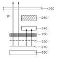
도 2는 본 발명의 제 2 실시예에 따른 면상 발열 시트를 부분적으로 나타낸 단면도.
도 3 및 도 4는 상기 실시예들과 비교되는 예를 도시한 단면도들.
도 5 내지 도 8은 본 발명에 따른 실시예들 및 비교예들의 온도 특성을 나타낸 그래프들.
도 9는 본 발명에 따른 면상 발열 시트를 나타낸 평면도.
도 10은 본 발명에 따른 면상 발열 시트의 제조 방법을 나타내기 위하여 온도제어부의 위치 관계를 부분 적으로 확대한 평면도.
도 11은 본 발명에 따른 면상 발열시트의 온도 제어 방법을 나타낸 그래프.
도 12는 본 발명에 제 3 실시예에 따른 면상 발열 시트를 나타낸 평면도.
도 13은 본 발명의 제 4 실시예에 따른 면상 발열 시트를 나타낸 평면도.
도 14는 본 발명의 제 5 실시예에 따른 면상 발열 시트를 나타낸 평면도.1 is a cross-sectional view partially showing a planar heating sheet according to a first embodiment of the present invention;
2 is a cross-sectional view partially showing a planar heating sheet according to a second embodiment of the present invention;
3 and 4 are sectional views showing an example compared with the above embodiments.
5 to 8 are graphs showing the temperature characteristics of Examples and Comparative Examples according to the present invention.
9 is a plan view showing a planar heating sheet according to the present invention.
10 is a partially enlarged plan view of a positional relationship of a temperature control unit in order to show a method of manufacturing a planar heating sheet according to the present invention;
11 is a graph showing a temperature control method of the planar heating sheet according to the present invention.
12 is a plan view showing a planar heating sheet according to a third embodiment of the present invention.
13 is a plan view showing a planar heating sheet according to a fourth embodiment of the present invention.
14 is a plan view showing a planar heating sheet according to a fifth embodiment of the present invention.
이하 첨부된 도면을 참조하여 본 발명에 따른 저전압 면상 발열 시트의 제조 방법 및 이를 이용하여 제조한 면상 발열 시트에 관하여 상세히 설명하기로 한다.Hereinafter, a method of manufacturing a low voltage planar heating sheet and a planar heating sheet manufactured using the same according to the present invention will be described in detail with reference to the accompanying drawings.
본 발명의 이점 및 특징, 그리고 그것들을 달성하는 방법은 첨부되는 도면과 함께 상세하게 후술되어 있는 실시예들을 참조하면 명확해질 것이다. 그러나, 본 발명은 이하에서 개시되는 실시예들에 한정되는 것이 아니라 서로 다른 다양한 형태로 구현될 것이며, 단지 본 실시예들은 본 발명의 개시가 완전하도록 하며, 본 발명이 속하는 기술분야에서 통상의 지식을 가진 자에게 발명의 범주를 완전하게 알려주기 위해 제공되는 것이며, 본 발명은 청구항의 범주에 의해 정의될 뿐이다. 명세서 전체에 걸쳐 동일 참조 부호는 동일 구성요소를 지칭한다.
BRIEF DESCRIPTION OF THE DRAWINGS The advantages and features of the present invention, and the manner of achieving them, will be apparent from and elucidated with reference to the embodiments described hereinafter in conjunction with the accompanying drawings. It should be understood, however, that the invention is not limited to the disclosed embodiments, but is capable of many different forms and should not be construed as limited to the embodiments set forth herein. Rather, these embodiments are provided so that this disclosure will be thorough and complete, To fully disclose the scope of the invention to those skilled in the art, and the invention is only defined by the scope of the claims. Like reference numerals refer to like elements throughout.
먼저, 본 발명에 따른 면상 발열 시트를 제조하는 방법은 탄소나노튜브(Carbon Nano Tube) 필름을 이용하여 발열부의 표면에 전원 공급을 위한 (+)메인 전극부, (-)메인 전극부, (+)서브 전극부 및 (-)서브 전극부를 각각 형성하되 서로 마주 보는 한 쌍의 상기 (+)서브 전극부와 (-)서브 전극부 간격이 1.5 ~ 20mm가 되도록 하는 것을 특징으로 한다.First, a method of manufacturing a planar heating sheet according to the present invention is a (+) main electrode part, (-) main electrode part, (+) for supplying power to the surface of the heating part using a carbon nanotube film. The sub-electrode part and the (-) sub-electrode part are respectively formed, and the distance between the pair of (+) sub-electrode parts and the (-) sub-electrode parts facing each other is 1.5 to 20 mm.
다음으로, 상기 (+)서브 전극부와 (-)서브 전극부에 의해서 정의되는 발열 영역의 상부에 온도제어부를 형성하되, 상기 발열 영역과 중첩되는 상기 온도제어부의 면적이 상기 온도제어부의 자체 평면 면적에 대해 15 ~ 100%가 되도록 형성하는 것을 특징으로 한다.Next, a temperature control unit is formed on the heating region defined by the (+) sub-electrode unit and the (-) sub-electrode unit, and the area of the temperature control unit overlapping the heat generating region has its own plane. Characterized in that it forms 15 to 100% with respect to the area.
또한, 상기 온도제어부에서 측정되는 온도가 상기 외피재의 표면에서 측정되는 온도와 일치될 수 있도록 상기 온도제어부 하부에 상기 온도제어부 크기의 부직포층을 형성하는 것을 특징으로 한다.In addition, the non-woven fabric layer having a size of the temperature control part may be formed under the temperature control part so that the temperature measured by the temperature control part coincides with the temperature measured on the surface of the shell material.
상기와 같은 방법에 의해 제조된 면상 발열 시트는 6 ~ 24볼트의 저전압에서도 용이하게 면상 발열이 일어 날 수 있고, -20℃의 조건에 노출시킨 후 1분 이내에 30℃까지 가열될 수 있으며, 10분 이내에 40℃까지 가열될 수 있도록 하고, 15분 이후에는 43℃ 전후의 온도를 유지할 수 있게 된다. 또한, 최대 온도가 45℃를 초과하는 경우 전류 공급이 오프(Off) 되고, 최하 온도가 32℃가 되면 다시 온(On) 상태로 전환될 수 있다. 이하에서는 상술한 방법에 의해 제조된 면상 발열 시트에 대하여 구체적으로 설명하는 것으로 한다.
The planar heating sheet prepared by the method as described above may easily generate planar heating even at a low voltage of 6 to 24 volts, and may be heated to 30 ° C. within 1 minute after exposure to a condition of −20 ° C., 10 It can be heated to 40 ℃ within minutes, and after 15 minutes it is possible to maintain the temperature around 43 ℃. In addition, when the maximum temperature exceeds 45 ℃ current supply is Off (Off), when the lowest temperature is 32 ℃ can be switched back to the On (On) state. Hereinafter, the planar heating sheet manufactured by the above-described method will be described in detail.
도 1은 본 발명의 제 1 실시예에 따른 면상 발열 시트를 부분적으로 나타낸 단면도이다.1 is a cross-sectional view partially showing a planar heating sheet according to a first embodiment of the present invention.
도 1을 참조하면, 먼저 본 발명에 따른 면상 발열 시트는 상부 및 하부 외피재에 의해서 보호가 되고 있다. 그러나 하부 외피재는 반드시 필요한 사항이 아니므로 여기서는 생략하는 것으로 한다.Referring to Figure 1, first, the planar heating sheet according to the present invention is protected by the upper and lower outer shell material. However, the lower skin is not necessary and will be omitted here.
다음으로, 하부 외피재 상부에는 시트 형태의 단열층(100)이 형성된다.Next, the
그 다음으로, 단열층(100) 상부에는 발열층의 접착을 위한 양면 접착층(120)이 형성된다.Next, a double-sided
그 다음으로, 양면 접착층(120) 상부에는 시트의 최외곽 모서리 부분 중 선택된 2부분에 맞추어 (+)메인 전극부와 (-)메인 전극부가 형성된다. 이때, (+)메인 전극부와 (-)메인 전극부는 서로 평행하게 형성되는 것이 바람직하며, Ag 또는 Cu와 같은 고 전도성 물질로 형성되는 것이 바람직하다.Next, the (+) main electrode part and the (−) main electrode part are formed on the double-sided
그 다음으로, (+)메인 전극부와 (-)메인 전극부에서 각각 서로 마주 보는 방향으로 연장되되, 서로 마주 보는 간격이 1.5 ~ 20mm가 되도록 (+), (-)서브 전극부가 형성된다. 이때 층간 구조를 설명하는 본 단면도에서는 (+), (-)메인 전극부 및 (+), (-)서브 전극부가 나타나지 않으므로 이들을 통칭하여 전극부층(120)로 표시하였다.Next, each of the (+) main electrode portion and the (-) main electrode portion extends in a direction facing each other, and the (+) and (-) sub electrode portions are formed such that the intervals facing each other are 1.5 to 20 mm. In this cross-sectional view illustrating the interlayer structure, (+), (-) main electrode portion and (+), (-) sub electrode portion do not appear, so these are collectively referred to as
그 다음으로, 전극부층(120) 상부에 탄소나노튜브(Carbon Nano Tube) 필름으로 이루어지는 발열부(130)가 형성된다. 이때, 탄소나노튜브 필름에 의해서 6 ~ 24볼트의 저전압 작동이 가능한 면상 발열 시트 제조가 가능하게 되었으며, 그 구체적 조건으로 상기 (+), (-)서브 전극부 사이의 간격을 들 수 있다. (+), (-)서브 전극부의 간격이 1.5mm 미만으로 형성되는 경우에는 원하는 발열량을 얻을 수 없었으며, (+), (-)서브 전극부의 간격이 20mm를 초과하는 경우에는 저전압 작동이 불안전하게 일어나는 문제가 있었다.Next, a
그 다음으로, 발열부(130) 상부에 베이스 필름(140)이 형성된다. 이때, 베이스 필름(140)은 PET 필름을 이용하여 형성하는 것이 바람직하며, 발열부(130)의 열을 효율적으로 상부 외피재까지 전달할 수 있는 역할을 하는 동시에, 발열부(130)를 보호하는 기능을 수행한다.Next, the
따라서, 베이스 필름(140) 상부에는 외피재(180)가 형성된다. 그리고, 발열부(130)의 열을 감지하여, 전극부층(120)에 전달되는 전압을 끊었다가 소정 온도 이하로 내려갈 경우 다시 전압을 연결하여 발열이 일어날 수 있도록 하는 온도조절부(170)를 외피재(180) 및 베이스 필름(140) 사이의 영역에 형성한다.Therefore, the
이때, 온도조절부(170)가 베이스 필름(140)과 직접 접속되는 경우, 외피재(180)를 통하여 사용자가 느끼는 온도와 온도조절부(170)에서 측정되는 온도 사이에 차이가 발생할 수 있으므로, 이를 방지하기 위하여 본 발명에서는 온도제어부(170)의 하부 및 상기 베이스 필름(140) 사이에 부직포(160)를 형성한다.In this case, when the
여기서, 부직포(170)는 온도제어부(170)의 평면과 대응되는 크기로 형성하며, 부직포접착층(150)에 의해서 베이스 필름(140) 상부에 고정될 수 있도록 하는 것이 바람직하다. 이때, 부직포(160)의 면적은 온도제어부(170) 면적의 1 ~ 1.5배 되는 면적이 되도록 하고, 단위면적당 100 ~ 200g의 질량을 가지는 제품을 사용하는 바람직하다. 부직포(160)의 단위 면적이 온도제어부(170) 보다 작거나, 1.5배를 초과하는 크기로 더 커지는 경우, 부직포가(160) 없는 상태와 동일하게 온도차가 발생하였으며, 부직포(160)의 단위 면적당 질량이 100g 미만이거나, 200g을 초과하는 제품을 사용하였을 때에도 부직포(160)가 없는 상태와 동일하게 온도차가 발생하였다.
Here, the
도 2는 본 발명의 제 2 실시예에 따른 면상 발열 시트를 부분적으로 나타낸 단면도이다.2 is a cross-sectional view partially showing a planar heating sheet according to a second embodiment of the present invention.
도 2는 탄소나노튜브(Carbon Nano Tube) 필름으로 이루어지는 발열부(210) 상부에 (+), (-)메인 전극부 및 (+), (-)서브 전극부를 포함하는 전극부층(220)이 형성되는 실시예를 나타낸 것으로, 제 2 실시예에서는 발열부(210)의 하부에 베이스 필름(200)을 형성하여, 베이스 필름(200)에 의해서 상부의 발열부(210) 및 전극부층(220)이 보호될 수 있는 구조로 형성한다.2 shows an
다음으로, 전극부층(220) 상부에 양면 접착층(230)을 형성하고 그 상부에 외피재(260)를 형성하되, 상술한 제 1 실시예에서와 같이 온도제어부(250) 및 부직포(240)를 외피재(260)와 양면 접착층(230) 사이에 형성한다.
Next, a double-
도 3 및 도 4는 상기 실시예들과 비교되는 예를 도시한 단면도들이다.3 and 4 are sectional views showing an example compared with the above embodiments.
도 3은 부직포의 기능을 비교하기 위하여 상술한 제 1 실시예에서 부직포를 제외한 구조로 형성한 면상 발열 시트를 나타낸 것이고, 도 4는 온도제어부의 기능을 비교하기 위하여 제 1 실시예에서 온도제어부 및 부직포를 제외한 구조로 형성한 면상 발열 시트를 나타낸 것이다.Figure 3 shows a planar heating sheet formed in a structure excluding the nonwoven fabric in the first embodiment described above to compare the functions of the nonwoven fabric, Figure 4 is a temperature control unit and the first embodiment to compare the function of the temperature control unit The planar heating sheet formed by the structure except the nonwoven fabric is shown.
따라서, 도 3의 비교예1은 하부에서부터 단열층(300), 양면 접착층(310), 전극부층(320), 발열부(330), 베이스 필름(340) 및 외피재(360)의 구조로 형성하되, 베이스 필름(340)과 외피재(360) 사이에 부직포를 제외시킨 형태의 단순 온도조절부(350)만을 삽입한 구조로 형성하였다.Therefore, Comparative Example 1 of FIG. 3 has a structure of a
다음으로, 도 4의 비교예2는 하부에서부터 단열층(400), 양면 접착층(410), 전극부층(420), 발열부(430), 베이스 필름(440) 및 외피재(460)의 구조로 형성하고, 온도조절부를 삽입하지 않은 구조로 형성하였다.Next, Comparative Example 2 of FIG. 4 has a structure of a
상술한 바와 같이, 실시예1(제 1 실시예), 실시예2(제 2 실시예), 비교예1 및 비교예2의 면상 발열 시트를 5×5㎠의 크기로 제조한 후에 온도조절부에서의 온도와 외피재에서의 온도를 각각 측정하여 그래프에 표시하였다. 이때, 온도조절부를 사용하는 실시예 및 비교예는 경인전자의 제품명 104S인 열동소자를 사용하였고, 서브 전극부와의 중첩면적이 40%가 되도록하였고, 6 ~ 24볼트의 전원을 이용하여 43℃에서 전류가 차단되고, 34℃에서 전류가 다시 흐르도록 제어하였다.
As described above, after the planar heating sheet of Example 1 (First Example), Example 2 (Second Example), Comparative Example 1 and Comparative Example 2 was manufactured to a size of 5 x 5
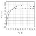
도 5 내지 도 8은 본 발명에 따른 실시예들 및 비교예들의 온도 특성을 나타낸 그래프들이다.5 to 8 are graphs showing temperature characteristics of Examples and Comparative Examples according to the present invention.
도 5는 실시예1에 대한 결과 그래프이고, 도 6은 실시예2에 대한 결과 그래프이고, 도 7은 비교예1에 대한 결과 그래프이고, 도 8은 비교예2에 대한 결과 그래프이다.5 is a result graph for Example 1, FIG. 6 is a result graph for Example 2, FIG. 7 is a result graph for Comparative Example 1, and FIG. 8 is a result graph for Comparative Example 2.
도 5 및 도 6을 참조하면, 실시예1 및 실시예2의 경우 온(On), 오프(Off)가 수행되고 있는 온도조절부의 온도는 40℃를 전후하여 일정한 패턴을 가지고 있으며, 이에 따라서 외피재에서 측정되는 온도 또한 45 ~ 50℃ 사이에서 일정하게 유지되고 있는 것을 알 수 있다.
5 and 6, in the case of the first and second embodiments, the temperature of the temperature control unit where On and Off are being performed has a constant pattern around 40 ° C., and accordingly, It can be seen that the temperature measured in the ash is also kept constant between 45 ~ 50 ℃.
그러나, 비교예1의 결과인 도 7의 경우에는 부직포가 존재하지 않으므로, 온(On), 오프(Off) 온도가 일정하게 유지되지 못하고 있으며, 이에 따라서 외피재에서 측정되는 온도가 50℃를 초과하고 매우 불규칙적으로 변화되고 있음을 알 수 있다.However, in the case of FIG. 7, which is a result of Comparative Example 1, since the nonwoven fabric does not exist, the on and off temperatures are not kept constant. Accordingly, the temperature measured in the outer cover material exceeds 50 ° C. It can be seen that the change is very irregular.
또한, 온도조절부가 구비되지 않은 비교예2의 결과인 도 8의 경우에는 외피재에서의 온도가 지속적으로 증가하여 80℃까지 상승하는 것을 볼 수 있다.In addition, in the case of FIG. 8, which is the result of Comparative Example 2 without the temperature control unit, it can be seen that the temperature in the shell material continuously increases and rises to 80 ° C.
이는 온도조절부 하부에 형성된 부직포가 온도의 급격한 변동을 조절하기 때문이다. 즉, 온도조절부의 온도가 급격히 가열되어 외피재의 온도보다 먼저 오프(Off)가 되고, 반대로 온도조절부의 온도가 외피재보다 더 빨리 냉각되어, 외피재의 온도가 충분히 내려가지 않은 상태에서 다시 온(On) 상태로 되어 불규칙한 가열이 이루어지지 않도록 하기 때문이다.This is because the nonwoven fabric formed in the lower part of the temperature control part controls the sudden change in temperature. That is, the temperature of the temperature controller is rapidly heated to be off before the temperature of the jacket, and conversely, the temperature of the temperature controller is cooled faster than the jacket, so that the temperature of the jacket is not sufficiently lowered. This is because it prevents irregular heating from happening.
이상에서 설명한 바와 같이, 본 발명에 따른 면상 발열 시트는 온도조절부를 외피재 하부에 위치시키되, 온도조절부의 하부에 부직포를 더 형성함으로써, 면상 발열 시트의 온도 제어 특성을 향상시킬 수 있도록 한다.As described above, the planar heating sheet according to the present invention is to place the temperature control portion under the outer cover material, by further forming a non-woven fabric in the lower portion of the temperature control portion, it is possible to improve the temperature control characteristics of the planar heating sheet.
이때, 서브 전극부 사이의 가열 영역과 온도조절부가 중첩되는 영역의 넓이에 따라서도 면상 발열 시트의 온도 조절 능력이 변화할 수 있는데, 그 구체적인 사항을 살펴보면 다음과 같다.
In this case, the temperature control ability of the planar heating sheet may also vary according to the width of the heating region between the sub-electrode portions and the region where the temperature control portion overlaps.
도 9는 본 발명에 따른 면상 발열 시트를 나타낸 평면도이다.9 is a plan view showing a planar heating sheet according to the present invention.
도 9는 본 발명에서 주요 구성을 나타낸 것으로, 면상 발열부(500) 상부에 (+)메인 전극부(510), (-)메인 전극부(515), (+)서브 전극부(525) 및 (-)서브 전극부(520)가 구비된 형태를 나타낸 것이다. 이때, 메인 전극부 및 서브 전극부는 발열부의 상부 표면 또는 하부 표면에 형성될 수 있다.9 shows a main configuration in the present invention, the (+)
여기서, (+)서브 전극부(525) 및 (-)서브 전극부(520)는 서로 마주 보는 방향으로 각각 메인 전극부로부터 연장되는 형태가 되고, 서로 마주 보는 한 쌍의 서브 전극부 사이의 영역이 발열 영역(550)이 되고 있으며, 발열 영역(550) 상부에 온도조절부(600)가 형성된다. 이때, 발열 영역(550)은 한 쌍의 서브 전극부에 의해서 형성될 수도 있지만, 복수 쌍이 서브 전극부에 의해서 형성될 수도 있다. 이에 관한 구체적 실시예는 하기 도 12 내지 도 14에서 설명하는 것으로 하며, 이하에서는 한 쌍의 서브 전극부를 기준으로 설명하는 것으로 한다.
Here, the (+)
도 10은 본 발명에 따른 면상 발열 시트의 제조 방법을 나타내기 위하여 온도제어부의 위치 관계를 부분 적으로 확대한 평면도이다.10 is a partially enlarged plan view of the positional relationship of the temperature control unit in order to show the manufacturing method of the planar heating sheet according to the present invention.
도 10을 참조하면, (+)서브 전극부(525) 및 (-)서브 전극부(520) 사이의 간격(D1)이 1.5 ~ 20mm가 되도록 형성하는 것이 바람직하며, 온도조절부(600)의 평면 면적과 중첩되는 발열 영역의 면적이 온도조절부(600) 면적의 15 ~ 100%가 되도록 형성하는 것이 바람직하다.Referring to FIG. 10, the distance D1 between the (+)
이때, 발열 영역(550) 식별을 위하여 각 서브 전극부의 외각에 표시를 하였으나, 이는 실제 적용되는 사항이 아니므로, 온도조절부(600)의 발열 중첩 영역(620)은 도시된 영역에 의해서 정의되는 것으로 한다.In this case, the sub-electrode portion is marked on the outer surface of the
여기서, 발열 중첩 영역(620)의 면적 비율에 따른 면상 발열 시트의 온도 제어 방법을 살펴보면, 다음과 같이 설명될 수 있다.Here, the temperature control method of the planar heating sheet according to the area ratio of the
실험 조건은 상술한 실시예1과 동일하게 유지하였으며, 상기 도 9에 도시된 구조에서 (+)서브 전극부(525) 및 (-)서브 전극부(520) 사이의 간격(D1)을 조절하여 발열 중첩 영역(620)이 12%, 13%, 40%, 60% 및 100%가 되도록 하여 각각 실험을 진행하였고, 그 결과는 다음과 같다.
Experimental conditions were maintained in the same manner as in Example 1, and the distance D1 between the (+)
도 11은 본 발명에 따른 면상 발열시트의 온도 제어 방법을 나타낸 그래프이다.11 is a graph illustrating a temperature control method of the planar heating sheet according to the present invention.
도 11을 참조하면, 온도조절부에 대하여 서브 전극부 사이의 간격이 중첩되는 면적의 비율이 13 ~ 100%인 경우 43±2℃의 범위에서 정상적으로 오프(Off)가 수행되고 있으며, 34±2℃의 범위에서 정상적으로 온(On)이 수행되고 있다.Referring to FIG. 11, when the ratio of the area where the intervals between the sub-electrode parts overlap with respect to the temperature controller is 13 to 100%, off is normally performed in a range of 43 ± 2 ° C., and 34 ± 2 On is normally performed in the range of ° C.
바람직하게는 발열 중첩 영역이 40%인 결과 그래프(-▲-)가 가장 안정적이고 우수한 온도 제어 특성을 나타내고 있다.Preferably, the resultant graph (− ▲ −) having 40% of the exothermic overlap region shows the most stable and excellent temperature control characteristic.
상기한 바와 같이, 본 발명에 따른 면상 발열 시트 및 이를 이용하여 온도를 제어하는 방법은 온도조절부와 발열 영역이 중첩되는 면적을 조절하는 것에 의해서도 그 특성을 향상시킬 수 있다.As described above, the planar heating sheet according to the present invention and a method for controlling temperature using the same may improve its characteristics by adjusting an area where the temperature control unit and the heating region overlap.
이와 관련하여, 본 발명에 따른 면상 발열 시트는 (+), (-)서브 전극부의 선폭 조절에 의한 (+)서브 전극부와 (-)서브 전극부 사이의 간격 조절도 가능하며, 그에 따른 구체적 실시예를 살펴보면 다음과 같다.
In this regard, the planar heating sheet according to the present invention can also adjust the distance between the (+) sub-electrode part and the (-) sub-electrode part by adjusting the line width of the (+) and (-) sub-electrode parts, and thus Looking at the embodiment as follows.
도 12는 본 발명에 제 3 실시예에 따른 면상 발열 시트를 나타낸 평면도이다.12 is a plan view showing a planar heating sheet according to a third embodiment of the present invention.
도 12를 참조하면, 탄소나노튜브를 이용하여 형성된 면상 발열부(700) 상부에 코일 형태로 구비되는 (+)메인 전극부(710)와 (-)메인 적극부(715)가 구비되고, 각 메인 전극부의 코일에서 연장되어 (+)서브 전극부(725) 및 (-)서브 전극부(715)가 형성된다.Referring to FIG. 12, a (+)
이와 같은 실시예의 적용 가능 여부를 실험하기 위하여 한 쌍의 서브 전극부의 두께(T1)는 1mm로 형성하였으며, (+)서브 전극부(725) 및 (-)서브 전극부(715) 사이의 간격(D2)은 4mm로 형성하였다.In order to test the applicability of such an embodiment, the thickness T1 of the pair of sub-electrode parts was formed to be 1 mm, and the gap between the (+)
다음으로, 발생되는 발열 영역(750)을 4mm로 정의하고, 상기 실시예1의 구조를 가지는 면상 발열 시트를 적용하였다. 온도조절부인 열동소자는 지름이 20mm인 제품을 사용하였으며, 작동 전압은 6 ~ 24볼트로 하여 실험을 진행하였다.Next, the generated
그 결과 평균 44℃의 온도에서 오프(Off)가 수행되었으며, 34℃의 온도에서 온(On)이 수행되었다.As a result, Off was performed at an average temperature of 44 ° C., and On was performed at a temperature of 34 ° C.
아울러, 상기와 같은 제 3 실시예의 형태로 (+)서브 전극부(725) 및 (-)서브 전극부(715) 사이의 간격(D2)이 1.5mm인 전극부를 형성할 수 있었으며, 이때 중첩영역이 13%가 될 수 있도록 열동소자의 지름이 15mm인 제품을 사용한 실험도 진행하였다.In addition, in the form of the third embodiment as described above, an electrode portion having a distance D2 between the (+)
그 결과 평균 45℃의 온도에서 오프(Off)가 수행되었으며, 34℃의 온도에서 온(On)이 수행되었다.As a result, Off was performed at an average temperature of 45 ° C., and On was performed at a temperature of 34 ° C.
아울러, 상기 실험 조건을 기준으로 (+)서브 전극부(725) 및 (-)서브 전극부(715) 사이의 간격(D2)이 1.4mm, 1mm, 0.5mm인 경우에도 실험을 진행하였으며, 그 결과는 하기 표 1에 표시하였다.
In addition, the experiment was conducted even when the distance (D2 ) between the (+)
도 13은 본 발명의 제 4 실시예에 따른 면상 발열 시트를 나타낸 평면도이다.13 is a plan view showing a planar heating sheet according to a fourth embodiment of the present invention.
도 13을 참조하면, 상기 제 3 실시예와 같이 코일 형태의 (+), (-)메인 전극부(810, 815)와 (+), (-)서브 전극부(825, 820)를 형성하되, 한 쌍의 서브 전극부의 두께(T2)는 0.5mm로 형성하였으며, (+)서브 전극부(825) 및 (-)서브 전극부(815) 사이의 간격(D3)은 2mm로 형성하였다.Referring to FIG. 13, as in the third embodiment, the positive electrode (+) and (−)
그리고, 여기서의 발열 영역(850)은 한 쌍의 서브 전극부를 이용한 것이 아니라, 각 서브 전극부가 서로 엇갈리게 배열된 복수개의 서브 전극부들 사이의 간격(D3×3=6mm)으로 정의하였다.The
아울러, 상기와 같은 조건에서 서브 전극부의 두께는 자유롭게 조절이 가능하며, (+)서브 전극부 및 (-)서브 전극부 사이의 간격은 최하 1.5mm이상이 되도록 하면, 본 발명에 따른 면상 발열 시트의 작동 조건을 충족시킬 수 있는 것으로 조사되었다.
In addition, under the above conditions, the thickness of the sub-electrode part can be freely adjusted, and the spacing between the (+) sub-electrode part and the (-) sub-electrode part is at least 1.5 mm or more, and the planar heating sheet according to the present invention. It was found that the operating conditions of can be met.
도 14는 본 발명의 제 5 실시예에 따른 면상 발열 시트를 나타낸 평면도이다.14 is a plan view showing a planar heating sheet according to a fifth embodiment of the present invention.
도 14를 참조하면, 상기 제 3 실시예와 같이 코일 형태의 (+), (-)메인 전극부(910, 915)와 (+), (-)서브 전극부(925, 920)를 형성하되, 한 쌍의 서브 전극부의 두께(T3)는 0.2mm로 형성하였으며, (+)서브 전극부(925) 및 (-)서브 전극부(915) 사이의 간격(D4)은 1.5mm로 형성하였다.Referring to FIG. 14, the positive electrode (910) and the negative electrode (910) and the negative electrode (925) and the (-)
그리고, 여기서의 발열 영역(950)은 한 쌍의 서브 전극부를 이용한 것이 아니라, 각 서브 전극부가 서로 엇갈리게 배열된 복수개의 서브 전극부들 사이의 간격(D4×13=19.5mm)으로 정의하였다.The
아울러, 상기 제 3 및 제 4 실시예와 같은 조건에서 (+)서브 전극부 및 (-)서브 전극부 사이의 간격을 최하 0.5mm까지 조절하여 전체 간격이 22mm가 되는 시점까지 실험을 진행하였으며, 그 종합적인 결과들은 하기 표 1에 나타내었다.
In addition, under the same conditions as in the third and fourth embodiments, the experiment was conducted until the total interval became 22 mm by adjusting the distance between the (+) sub electrode part and the (-) sub electrode part to a minimum of 0.5 mm. The overall results are shown in Table 1 below.
(mm)interval
(mm)
상기 표 1을 참조하면, 단일 서브 전극부 또는 복수개의 서브 전극부 사이의 간격이 1.5mm 인 경우에 오프(Off) 온도가 45℃이고, 온(On) 온도가 34℃로 나타나고 있어, 서브 전극부 사이의 간격이 1.5mm 미만인 경우 온도 제어 특성이 떨어지고 있음을 알 수 있다.Referring to Table 1, when the interval between the single sub-electrode portion or the plurality of sub-electrode portions is 1.5 mm, the off temperature is 45 ° C and the on temperature is 34 ° C. It can be seen that the temperature control characteristics are deteriorated when the distance between the parts is less than 1.5 mm.
또한, 온도제어부의 최대 지름이 되는 20mm를 초과한 20.1mm의 간격을 갖는 경우 오프(Off) 온도가 41℃이고, 온(On) 온도가 33.5℃로 나타나고 있어, 온도 제어 특성이 저하되고 있음을 알 수 있다.In addition, when there is an interval of 20.1 mm exceeding 20 mm, which is the maximum diameter of the temperature control part, the off temperature is 41 ° C and the on temperature is 33.5 ° C, indicating that the temperature control characteristics are deteriorated. Able to know.
상술한 바와 같이 본 발명에 따른 면상 발열 시트는 탄소나노튜브(Carbon Nano Tube)를 그라비아로 인쇄한 필름을 발열부로 사용함으로써, 6 ~ 24볼트의 저전압에서도 용이하게 면상 발열이 일어 날 수 있도록 하고, 시트의 전면에서 고르게 발열이 일어 날 수 있도록 한다.As described above, the planar heating sheet according to the present invention uses a film printed with gravure carbon nanotubes as a heating unit so that the planar heating can easily occur even at a low voltage of 6 to 24 volts. Allow heat to flow evenly from the front of the seat.
아울러, 본 발명은 상기 면상 발열 시트의 온도제어부를 서브 전극부의 상부에 위치시키되, 발열 부분의 크기를 1.5 ~ 20mm로 형성하고, 여기에 온도제어부가 중첩되는 영역의 크기를 13 ~ 100%가 되도록 조절하여, 온도 제어 특성을 향상시킬 수 있다.In addition, the present invention is to position the temperature control unit of the planar heating sheet on the upper portion of the sub-electrode portion, the size of the heat generating portion is formed to 1.5 ~ 20mm, so that the size of the region where the temperature control unit overlaps 13 to 100% By adjusting, the temperature control characteristic can be improved.
또한, 본 발명은 온도제어부의 하부에 부직포를 형성함으로써, 외부에서 느낄 수 있는 온도변화와 동일한 온도에서 제어가 이루어질 수 있도록 하고, 최대 온도가 45℃를 초과하는 경우 전류 공급이 오프(Off) 되고, 최하 온도가 32℃가 되면 다시 온(On) 상태로 전환될 수 있도록 함으로써, 휴대용 방석과 같은 소형 전열기구 및 자동차의 열선시트와 같은 제품에도 용이하게 적용할 수 있다.
In addition, the present invention by forming a non-woven fabric in the lower portion of the temperature control unit, so that the control can be made at the same temperature as the temperature change can be felt from the outside, when the maximum temperature exceeds 45 ℃ current supply is Off (Off) When the lowest temperature reaches 32 ° C., the device can be switched back to an on state, and thus it can be easily applied to products such as a small heating device such as a portable cushion and a heating sheet of an automobile.
이상에서는 본 발명의 실시예를 중심으로 설명하였지만, 본 발명이 속하는 기술분야에서 통상의 지식을 가진 기술자의 수준에서 다양한 변경이나 변형을 가할 수 있다. 이러한 변경과 변형은 본 발명이 제공하는 기술 사상의 범위를 벗어나지 않는 한 본 발명에 속한다고 할 수 있다. 따라서 본 발명의 권리범위는 이하에 기재되는 청구범위에 의해 판단되어야 할 것이다.
Although the preferred embodiments of the present invention have been disclosed for illustrative purposes, those skilled in the art will appreciate that various modifications, additions and substitutions are possible, without departing from the scope and spirit of the invention as disclosed in the accompanying claims. These changes and modifications may be made without departing from the scope of the present invention. Accordingly, the scope of the present invention should be determined by the following claims.
100, 300, 400 : 단열층
110, 230, 310, 410 : 양면접착 필름
120, 220, 320, 420 : 전극부층
130, 210, 500, 700, 800, 900 : 발열부
140, 340, 440 : 베이스 필름
150 : 부직포접착층
160, 240 : 부직포
170, 250, 350, 600 : 온도제어부
180, 260, 360, 450 : 외피재
510, 710, 810, 910 : (+)메인 전극부
515, 715, 815, 915 : (-)메인 전극부
520, 720, 820, 920 : (-)서브 전극부
525, 725, 825, 925 : (+)서브 전극부
550, 750, 850, 950 : 발열 영역
620 : 발열 중첩 영역100, 300, 400: heat insulation layer
110, 230, 310, 410: double sided adhesive film
120, 220, 320, 420: electrode layer
130, 210, 500, 700, 800, 900: heating section
140, 340, 440: base film
150: non-woven adhesive layer
160, 240 nonwoven fabric
170, 250, 350, 600: temperature control unit
180, 260, 360, 450: shell material
510, 710, 810, 910: (+) main electrode portion
515, 715, 815, 915: (-) main electrode part
520, 720, 820, 920: (-) sub electrode part
525, 725, 825, 925: (+) sub electrode part
550, 750, 850, 950: heating zone
620: fever overlapping area
Claims (17)
Translated fromKorean탄소나노튜브(Carbon Nano Tube) 필름을 이용하여 발열부를 형성하는 단계;
상기 발열부의 표면에 전원 공급을 위한 (+)메인 전극부와 (-)메인 전극부를 서로 이격된 형태로 형성하는 단계;
상기 각 메인 전극부에서 서로 마주 보는 방향으로 연장되는 하나 이상의 (+)서브 전극부와 (-)서브 전극부를 각각 형성하되 서로 마주 보는 한 쌍의 상기 (+)서브 전극부와 (-)서브 전극부 간격이 1.5 ~ 20mm가 되도록 하는 단계;
상기 (+)서브 전극부와 (-)서브 전극부에 의해서 정의되는 발열 영역의 상부에 온도제어부를 형성하되, 상기 발열 영역과 중첩되는 상기 온도제어부의 면적이 상기 온도제어부의 자체 평면 면적에 대해 15 ~ 100%가 되도록 형성하는 단계; 및
상기 온도제어부 하부에 상기 온도제어부 크기의 부직포층을 형성하여, 상기 온도제어부에서 측정되는 온도가 상기 외피재의 표면에서 측정되는 온도와 일치될 수 있도록 하는 단계를 포함하는 저전압 면상 발열 시트의 제조 방법.
In the method for producing a planar heating sheet having a heat generating portion inside the outer cover material,
Forming a heat generating unit using a carbon nanotube film;
Forming a (+) main electrode part and a (−) main electrode part for supplying power to the surface of the heat generating part in a form spaced apart from each other;
At least one (+) sub-electrode part and a (-) sub-electrode part respectively extending in the directions facing each other in the main electrode part, respectively, a pair of the (+) sub-electrode part and the (-) sub-electrode facing each other Making the minor spacing 1.5 to 20 mm;
A temperature control unit is formed on the heating region defined by the (+) sub-electrode unit and the (-) sub-electrode unit, and the area of the temperature control unit overlapping with the heat generating region is in relation to the self-planar area of the temperature control unit. Forming 15 to 100%; And
And forming a non-woven fabric layer having a size of the temperature control part under the temperature control part so that the temperature measured by the temperature control part can be matched with the temperature measured on the surface of the shell material.
상기 (+), (-)메인 전극부 및 (+), (-)서브 전극부는 상기 발열부의 하부 표면에 형성하는 것을 특징으로 하는 저전압 면상 발열 시트의 제조 방법.
The method of claim 1,
And the (+), (-) main electrode portion and (+), (-) sub electrode portion are formed on the lower surface of the heat generating portion.
상기 (+), (-)메인 전극부 및 (+), (-)서브 전극부 하부에 양면 접착층을 더 형성하고, 상기 양면 접착층 하부에 더 단열층을 형성하는 것을 특징으로 하는 저전압 면상 발열 시트의 제조 방법.
The method of claim 2,
A double-sided adhesive layer is further formed below the (+), (-) main electrode portion and (+), (-) sub-electrode portion, and a heat insulation layer is further formed below the double-sided adhesive layer. Manufacturing method.
상기 발열부 상부에 베이스 필름층을 더 형성하고, 상기 베이스 필름층 상부에 상기 부직포 및 상기 온도제어부의 순서로 적층하는 것을 특징으로 하는 저전압 면상 발열 시트의 제조 방법.
The method of claim 2,
A base film layer is further formed on the heat generating part, and the nonwoven fabric and the temperature control part are laminated in the order of the base film layer.
상기 부직포는 상기 베이스 필름층 상부에 접착층을 이용하여 고정시키는 것을 특징으로 하는 저전압 면상 발열 시트의 제조 방법.
The method of claim 4, wherein
The nonwoven fabric is fixed to the base film layer by using an adhesive layer, characterized in that the low-voltage planar heating sheet manufacturing method.
상기 (+), (-)메인 전극부 및 (+), (-)서브 전극부는 상기 발열부의 상부 표면에 형성하는 것을 특징으로 하는 저전압 면상 발열 시트의 제조 방법.
The method of claim 1,
And the (+), (-) main electrode portion and (+), (-) sub electrode portion are formed on the upper surface of the heat generating portion.
상기 발열부 하부에 베이스 필름층을 더 형성하는 것을 특징으로 하는 저전압 면상 발열 시트의 제조 방법.
The method according to claim 6,
The base film layer is further formed under the heat generating portion.
상기 (+), (-)메인 전극부 및 (+), (-)서브 전극부 상부에 양면 접착층을 더 형성하고, 상기 양면 접착층 상부에 상기 부직포 및 상기 온도제어부를 순차적으로 적층하는 것을 특징으로 하는 저전압 면상 발열 시트의 제조 방법.
The method according to claim 6,
And further forming a double-sided adhesive layer on the (+), (-) main electrode portion and the (+) and (-) sub-electrode portion, and sequentially laminating the nonwoven fabric and the temperature control portion on the double-sided adhesive layer. The low voltage planar heating sheet manufacturing method.
상기 부직포는 상기 온도제어부 면적의 1 ~ 1.5배 되는 면적이 되도록 형성하는 것을 특징으로 하는 저전압 면상 발열 시트의 제조 방법.
The method of claim 1,
The nonwoven fabric is a method of manufacturing a low-voltage planar heating sheet, characterized in that formed to be an area 1 to 1.5 times the area of the temperature control unit.
상기 부직포는 단위면적당 100 ~ 200g의 질량을 가지는 제품을 사용하는 것을 특징으로 하는 저전압 면상 발열 시트의 제조 방법.
The method of claim 1,
The nonwoven fabric is a method for producing a low-voltage planar heating sheet, characterized in that using a product having a mass of 100 ~ 200g per unit area.
상기 하부 외피재 상부에 형성되는 시트 형태의 단열층;
상기 단열층의 상부에 형성되는 양면 접착층;
상기 양면 접착층 상부에 형성되는 (+)메인 전극부와 (-)메인 전극부;
상기 (+)메인 전극부와 (-)메인 전극부에서 각각 서로 마주 보는 방향으로 연장되되, 서로 마주 보는 간격이 1.5 ~ 20mm가 되도록 형성되는 (+)서브 전극부와 (-)서브 전극부;
상기 (+)메인 전극부, (-)메인 전극부, (+)서브 전극부 및 (-)서브 전극부 상부에 형성되며, 탄소나노튜브(Carbon Nano Tube) 필름으로 이루어지는 발열부;
상기 발열부 상부에 형성되는 베이스 필름;
상기 베이스 필름의 상부에 형성되되, (+)서브 전극부 및 (-)서브 전극부 사이의 간격과 중첩되는 부분의 면적이 자체 평면 면적에 대해 15 ~ 100%가 되도록 형성되는 온도제어부;
상기 온도제어부 하부 및 상기 베이스 필름 사이에 상기 온도제어부의 평면과 대응되는 크기로 형성되는 부직포; 및
상기 온도제어부 상부에 형성되는 상부 외피재를 포함하는 것을 특징으로 하는 면상 발열 시트.
Lower shell material;
A heat insulation layer in the form of a sheet formed on the lower outer cover material;
A double-sided adhesive layer formed on the heat insulation layer;
(+) Main electrode portion and (-) main electrode portion formed on the double-sided adhesive layer;
(+) Sub-electrode parts and (-) sub-electrode parts extending in directions facing each other from the (+) main electrode part and (-) main electrode part, respectively, so that the intervals facing each other are 1.5 to 20 mm;
A heating part formed on the (+) main electrode part, the (−) main electrode part, the (+) sub electrode part, and the (−) sub electrode part and formed of a carbon nanotube film;
A base film formed on the heat generating unit;
A temperature control part formed on the base film, wherein the area of the portion overlapping the gap between the (+) sub electrode part and the (-) sub electrode part is 15 to 100% of its own planar area;
A nonwoven fabric formed between the lower portion of the temperature controller and the base film to have a size corresponding to a plane of the temperature controller; And
Planar heating sheet characterized in that it comprises an upper outer cover material formed on the temperature control unit.
상기 온도제어부는 온도 센서 또는 열동소자를 포함하는 것을 특징으로 하는 면상 발열 시트.
The method of claim 11,
And the temperature control part comprises a temperature sensor or a thermal element.
상기 열동소자의 지름은 15 ~ 22mm인 것을 특징으로 하는 면상 발열 시트.
The method of claim 12,
Planar heating sheet, characterized in that the diameter of the thermal element is 15 ~ 22mm.
상기 면상 발열 시트는 6 ~ 24볼트의 전압에서 동작되는 것을 특징으로 하는 면상 발열 시트.
The method of claim 11,
And the planar heating sheet is operated at a voltage of 6 to 24 volts.
상기 면상 발열 시트는 외부 온도가 -20℃인 조건에서 작동된 후 1분 이내에 30℃까지 가열되도록 하며, 10분 이내에 40℃까지 가열될 수 있도록 하는 것을 특징으로 하는 면상 발열 시트.
The method of claim 11,
The planar heating sheet is a planar heating sheet characterized in that it is heated to 30 ℃ within 1 minute after operating in a condition that the external temperature is -20 ℃, and can be heated to 40 ℃ within 10 minutes.
상기 온도제어부는 45℃의 온도에서 오프(Off) 상태로 전환되도록 하고, 32℃의 온도에서 다시 온(On) 상태로 전환되도록 형성되는 것을 특징으로 하는 면상 발열 시트.
The method of claim 11,
The temperature control unit is to be switched to the off (Off) state at a temperature of 45 ℃, the planar heating sheet, characterized in that it is formed to be switched back to the on (On) at a temperature of 32 ℃.
상기 하부 외피재 상부에 형성되는 시트 형태의 베이스 필름;
상기 베이스 필름의 상부에 형성되며, 탄소나노튜브(Carbon Nano Tube) 필름으로 이루어지는 발열부;
상기 발열부 상부에 형성되는 (+)메인 전극부와 (-)메인 전극부;
상기 (+)메인 전극부와 (-)메인 전극부에서 각각 서로 마주 보는 방향으로 연장되되, 서로 마주 보는 간격이 1.5 ~ 20mm가 되도록 형성되는 (+)서브 전극부와 (-)서브 전극부;
상기 (+)메인 전극부, (-)메인 전극부, (+)서브 전극부 및 (-)서브 전극부 상부에 형성되는 양면 접착층;
상기 양면 접착층 상부에 형성되되, 상기 (+)서브 전극부와 (-)서브 전극부 사이의 간격과 중첩되는 부분의 면적이 자체 평면 면적에 대해 15 ~ 100%가 되도록 형성되는 온도제어부;
상기 온도제어부 하부 및 상기 양면 접착층 사이에 상기 온도제어부의 평면과 대응되는 크기로 형성되는 부직포; 및
상기 온도제어부 상부에 형성되는 상부 외피재를 포함하는 것을 특징으로 하는 면상 발열 시트.
Lower shell material;
A base film in a sheet form formed on the lower outer cover material;
A heat generation part formed on an upper portion of the base film and made of a carbon nanotube film;
(+) Main electrode portion and (-) main electrode portion formed on the heat generating portion;
(+) Sub-electrode parts and (-) sub-electrode parts extending in directions facing each other from the (+) main electrode part and (-) main electrode part, respectively, so that the intervals facing each other are 1.5 to 20 mm;
A double-sided adhesive layer formed on the (+) main electrode part, (−) main electrode part, (+) sub electrode part and (−) sub electrode part;
A temperature control part formed on the double-sided adhesive layer and formed such that an area of the portion overlapping the gap between the (+) sub electrode part and the (-) sub electrode part is 15 to 100% of its own planar area;
A nonwoven fabric formed between the lower portion of the temperature controller and the double-sided adhesive layer to have a size corresponding to a plane of the temperature controller; And
Planar heating sheet characterized in that it comprises an upper outer cover material formed on the temperature control unit.
Priority Applications (1)
| Application Number | Priority Date | Filing Date | Title |
|---|---|---|---|
| KR1020100010461AKR101171470B1 (en) | 2010-02-04 | 2010-02-04 | Method for fabricating low voltage plane heating sheet and plane heating sheet fabricated using the same |
Applications Claiming Priority (1)
| Application Number | Priority Date | Filing Date | Title |
|---|---|---|---|
| KR1020100010461AKR101171470B1 (en) | 2010-02-04 | 2010-02-04 | Method for fabricating low voltage plane heating sheet and plane heating sheet fabricated using the same |
Publications (2)
| Publication Number | Publication Date |
|---|---|
| KR20110090588A KR20110090588A (en) | 2011-08-10 |
| KR101171470B1true KR101171470B1 (en) | 2012-08-06 |
Family
ID=44928349
Family Applications (1)
| Application Number | Title | Priority Date | Filing Date |
|---|---|---|---|
| KR1020100010461AExpired - Fee RelatedKR101171470B1 (en) | 2010-02-04 | 2010-02-04 | Method for fabricating low voltage plane heating sheet and plane heating sheet fabricated using the same |
Country Status (1)
| Country | Link |
|---|---|
| KR (1) | KR101171470B1 (en) |
Families Citing this family (2)
| Publication number | Priority date | Publication date | Assignee | Title |
|---|---|---|---|---|
| KR101304583B1 (en)* | 2012-02-02 | 2013-09-05 | 삼성중공업 주식회사 | Apparatus for drying |
| CN119586319A (en)* | 2022-06-07 | 2025-03-07 | 诺里威士达股份有限公司 | Planar heating element and method for manufacturing the same |
Citations (2)
| Publication number | Priority date | Publication date | Assignee | Title |
|---|---|---|---|---|
| JP2002367757A (en) | 2001-06-05 | 2002-12-20 | Matsushita Electric Ind Co Ltd | Heater unit |
| KR100925358B1 (en) | 2009-05-08 | 2009-11-09 | 경기수 | A heating mat |
- 2010
- 2010-02-04KRKR1020100010461Apatent/KR101171470B1/ennot_activeExpired - Fee Related
Patent Citations (2)
| Publication number | Priority date | Publication date | Assignee | Title |
|---|---|---|---|---|
| JP2002367757A (en) | 2001-06-05 | 2002-12-20 | Matsushita Electric Ind Co Ltd | Heater unit |
| KR100925358B1 (en) | 2009-05-08 | 2009-11-09 | 경기수 | A heating mat |
Also Published As
| Publication number | Publication date |
|---|---|
| KR20110090588A (en) | 2011-08-10 |
Similar Documents
| Publication | Publication Date | Title |
|---|---|---|
| WO2018166137A1 (en) | High-performance carbon composite material far-infrared planar heating body and use thereof | |
| CN104902594A (en) | Intelligent temperature control thermal underwear | |
| US20160270544A1 (en) | Temperature control mattress with thermoelectric fabric | |
| KR20160036898A (en) | A Jjimjilbang inside structrue | |
| KR101171470B1 (en) | Method for fabricating low voltage plane heating sheet and plane heating sheet fabricated using the same | |
| KR100491225B1 (en) | Surface type heater which emits infrared rays | |
| CN204838098U (en) | Waist protector | |
| CN105451380B (en) | Heating pad | |
| KR100750707B1 (en) | Plate heater and method for manufacturing the same | |
| KR101438465B1 (en) | Portable auxiliary heating apparatus | |
| CN112601299A (en) | Graphene heating structure with distributed soaking function | |
| CN109237593B (en) | Greenhouse assembly, preparation method thereof and greenhouse with greenhouse assembly | |
| KR20110039957A (en) | Heating film | |
| KR102051429B1 (en) | Mattress with cold and warm air for bedsore prevention | |
| CN105433466B (en) | knee pads | |
| KR200280370Y1 (en) | Table with thin heating system | |
| KR200414838Y1 (en) | Bed linen with Macsumite ceramics | |
| CN101161218B (en) | heating pad | |
| CN214046039U (en) | Heating structure of light wave room and light wave room using same | |
| KR101766581B1 (en) | The electrical heating matt of far infrared emission | |
| JP3943562B2 (en) | Floor heating device with potential generating function and potential generating function auxiliary device | |
| KR20140086678A (en) | Multi-functional ceramic heating implement | |
| CN212930181U (en) | Bathroom heating mirror | |
| KR200246237Y1 (en) | Far-infrared radiating sheet heater | |
| KR200324734Y1 (en) | electrically heating mat for pet |
Legal Events
| Date | Code | Title | Description |
|---|---|---|---|
| PA0109 | Patent application | St.27 status event code:A-0-1-A10-A12-nap-PA0109 | |
| A201 | Request for examination | ||
| PA0201 | Request for examination | St.27 status event code:A-1-2-D10-D11-exm-PA0201 | |
| PG1501 | Laying open of application | St.27 status event code:A-1-1-Q10-Q12-nap-PG1501 | |
| PN2301 | Change of applicant | St.27 status event code:A-3-3-R10-R13-asn-PN2301 St.27 status event code:A-3-3-R10-R11-asn-PN2301 | |
| R18-X000 | Changes to party contact information recorded | St.27 status event code:A-3-3-R10-R18-oth-X000 | |
| PN2301 | Change of applicant | St.27 status event code:A-3-3-R10-R13-asn-PN2301 St.27 status event code:A-3-3-R10-R11-asn-PN2301 | |
| D13-X000 | Search requested | St.27 status event code:A-1-2-D10-D13-srh-X000 | |
| D14-X000 | Search report completed | St.27 status event code:A-1-2-D10-D14-srh-X000 | |
| E701 | Decision to grant or registration of patent right | ||
| PE0701 | Decision of registration | St.27 status event code:A-1-2-D10-D22-exm-PE0701 | |
| GRNT | Written decision to grant | ||
| PR0701 | Registration of establishment | St.27 status event code:A-2-4-F10-F11-exm-PR0701 | |
| PR1002 | Payment of registration fee | St.27 status event code:A-2-2-U10-U11-oth-PR1002 Fee payment year number:1 | |
| PG1601 | Publication of registration | St.27 status event code:A-4-4-Q10-Q13-nap-PG1601 | |
| R18-X000 | Changes to party contact information recorded | St.27 status event code:A-5-5-R10-R18-oth-X000 | |
| FPAY | Annual fee payment | Payment date:20150624 Year of fee payment:4 | |
| PR1001 | Payment of annual fee | St.27 status event code:A-4-4-U10-U11-oth-PR1001 Fee payment year number:4 | |
| FPAY | Annual fee payment | Payment date:20160630 Year of fee payment:5 | |
| PR1001 | Payment of annual fee | St.27 status event code:A-4-4-U10-U11-oth-PR1001 Fee payment year number:5 | |
| P22-X000 | Classification modified | St.27 status event code:A-4-4-P10-P22-nap-X000 | |
| FPAY | Annual fee payment | Payment date:20170623 Year of fee payment:6 | |
| PR1001 | Payment of annual fee | St.27 status event code:A-4-4-U10-U11-oth-PR1001 Fee payment year number:6 | |
| FPAY | Annual fee payment | Payment date:20180528 Year of fee payment:7 | |
| PR1001 | Payment of annual fee | St.27 status event code:A-4-4-U10-U11-oth-PR1001 Fee payment year number:7 | |
| PC1903 | Unpaid annual fee | St.27 status event code:A-4-4-U10-U13-oth-PC1903 Not in force date:20190728 Payment event data comment text:Termination Category : DEFAULT_OF_REGISTRATION_FEE | |
| R18-X000 | Changes to party contact information recorded | St.27 status event code:A-5-5-R10-R18-oth-X000 | |
| PC1903 | Unpaid annual fee | St.27 status event code:N-4-6-H10-H13-oth-PC1903 Ip right cessation event data comment text:Termination Category : DEFAULT_OF_REGISTRATION_FEE Not in force date:20190728 | |
| PN2301 | Change of applicant | St.27 status event code:A-5-5-R10-R13-asn-PN2301 St.27 status event code:A-5-5-R10-R11-asn-PN2301 | |
| PN2301 | Change of applicant | St.27 status event code:A-5-5-R10-R13-asn-PN2301 St.27 status event code:A-5-5-R10-R11-asn-PN2301 |