KR101166255B1 - Electric conduction plate for induction heating cooking pot - Google Patents
Electric conduction plate for induction heating cooking potDownload PDFInfo
- Publication number
- KR101166255B1 KR101166255B1KR1020120042314AKR20120042314AKR101166255B1KR 101166255 B1KR101166255 B1KR 101166255B1KR 1020120042314 AKR1020120042314 AKR 1020120042314AKR 20120042314 AKR20120042314 AKR 20120042314AKR 101166255 B1KR101166255 B1KR 101166255B1
- Authority
- KR
- South Korea
- Prior art keywords
- conductive plate
- induction heating
- vertical portion
- heating cooking
- horizontal portion
- Prior art date
- Legal status (The legal status is an assumption and is not a legal conclusion. Google has not performed a legal analysis and makes no representation as to the accuracy of the status listed.)
- Active
Links
Images


Classifications
- A—HUMAN NECESSITIES
- A47—FURNITURE; DOMESTIC ARTICLES OR APPLIANCES; COFFEE MILLS; SPICE MILLS; SUCTION CLEANERS IN GENERAL
- A47J—KITCHEN EQUIPMENT; COFFEE MILLS; SPICE MILLS; APPARATUS FOR MAKING BEVERAGES
- A47J36/00—Parts, details or accessories of cooking-vessels
- A47J36/02—Selection of specific materials, e.g. heavy bottoms with copper inlay or with insulating inlay
- H—ELECTRICITY
- H05—ELECTRIC TECHNIQUES NOT OTHERWISE PROVIDED FOR
- H05B—ELECTRIC HEATING; ELECTRIC LIGHT SOURCES NOT OTHERWISE PROVIDED FOR; CIRCUIT ARRANGEMENTS FOR ELECTRIC LIGHT SOURCES, IN GENERAL
- H05B6/00—Heating by electric, magnetic or electromagnetic fields
- H05B6/02—Induction heating
- H05B6/10—Induction heating apparatus, other than furnaces, for specific applications
- H05B6/12—Cooking devices
- A—HUMAN NECESSITIES
- A47—FURNITURE; DOMESTIC ARTICLES OR APPLIANCES; COFFEE MILLS; SPICE MILLS; SUCTION CLEANERS IN GENERAL
- A47J—KITCHEN EQUIPMENT; COFFEE MILLS; SPICE MILLS; APPARATUS FOR MAKING BEVERAGES
- A47J27/00—Cooking-vessels
- A47J27/02—Cooking-vessels with enlarged heating surfaces
- A47J27/022—Cooking-vessels with enlarged heating surfaces with enlarged bottom
Landscapes
- Engineering & Computer Science (AREA)
- Food Science & Technology (AREA)
- Physics & Mathematics (AREA)
- Electromagnetism (AREA)
- Cookers (AREA)
Abstract
Description
Translated fromKorean본 발명은 유도가열 조리용기의 도전판에 관한 것으로, 더욱 상세하게는 유도가열을 통해 조리용기를 신속하게 가열할 수 있는 유도가열 조리용기의 도전판에 관한 것이다.
The present invention relates to a conductive plate of an induction heating cooking vessel, and more particularly, to a conductive plate of an induction heating cooking vessel that can quickly heat the cooking vessel through induction heating.
일반적으로 유도가열이란 전자기 유도에 의해 전기에너지를 열에너지로 변환시켜 가열하는 방법으로서, 이러한 가열 방법은 여러 다양한 분야에서 활용되고 있다.In general, induction heating is a method of heating electrical energy by converting electrical energy into thermal energy by electromagnetic induction. Such heating methods have been utilized in various fields.
특히 유도가열은 음식을 조리하는 데 사용되는 조리용기에도 적용되고 있으며, 유도가열 조리용기는 기능성 및 사용성이 우수하여 그 수요가 증가하고 있는 추세이다.In particular, induction heating is also applied to cooking containers used to cook food, and induction heating cooking containers have a trend of increasing demand due to their excellent functionality and usability.
이에 보조하여 유도가열 조리용기의 도전판에 대한 연구가 활발히 진행되고 있다.In support of this, research on conductive plates of induction cooking vessels has been actively conducted.
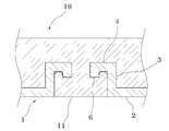
종래의 유도가열 조리용기의 도전판은 도 1에 도시되어 있는 바와 같이, 용기본체(10)의 하면에 접촉되는 본체부(2); 본체부(2)로부터 수직방향으로 연장 형성되는 수직부(3) 및 수직부(3)로부터 수평방향으로 연장 형성되는 수평부(4)로 이루어진다.The conductive plate of the conventional induction heating cooking vessel, as shown in Figure 1, the main body portion (2) in contact with the lower surface of the container body (10); It consists of a
그러나 위와 같은 도전판(1)은 1단으로 상향 절곡된 구조를 가짐으로써 수직부(3)의 길이를 길게 형성할 경우 용기본체(10)와의 체결력은 높일 수 있으나, 소성변형된 용기본체(10)의 체결부(11)가 수직부(3) 및 수평부(4)의 절곡부위에 완전히 밀착되지 못하여 도전판(1)이 변형되는 단점이 있다. 또한 수직부(3)의 길이를 짧게 형성할 경우 소성변형된 용기본체(10)의 체결부(11)가 수직부(3) 및 수평부(4)의 절곡부위에 완전히 밀착되나, 용기본체(10)와의 체결력이 저하되는 단점이 있다. 또한 수직부(3) 및 수평부(4)의 절곡부위 한 곳에만 응력이 집중됨으로써 도전판(1)의 체결상태를 견고하게 유지하는 데 한계가 있다.However, the
도 2 및 도 3은 종래 유도가열 조리용기의 도전판의 다른 실시형태를 도시한 것이다.2 and 3 show another embodiment of the conductive plate of the conventional induction heating cooking vessel.
도 2에 도시되어 있는 도전판(1)은 본체부(2)로부터 연장 형성되어 있는 수직부(3) 및 수평부(4) 사이에 경사부(5)가 형성됨으로써 소성변형된 용기본체(10)의 체결부(11)가 도전판(1)에 완전히 밀착되는 데 유리하다는 장점은 있으나, 도전판(1)의 접촉면적이 줄어들어 열전도 효율이 저하됨은 물론이고 경사부(5)를 따라 응력의 흐름이 발생되어 수평부(4) 및 경사부(5)의 절곡부위에 응력이 집중되는 문제점이 있다.In the
그리고 도 3에 도시되어 있는 도전판(1)은 본체부(2)와 연결되어 있는 수직부(3)로부터 연장 형성된 수평부(4)의 단부에 돌기부(6)가 형성됨으로써 도전판(1)의 체결력을 높일 수 있다는 장점은 있으나, 수평부(4) 및 돌기부(6)의 절곡부위에서 소성변형된 용기본체(10)의 체결부(11)와의 밀착이 완벽하게 이루어지지 못하여 도전판(1)의 변형이 발생되는 문제점이 있다. 또한 수직부(3) 및 수평부(4)의 절곡부위에 대부분의 응력이 집중되는 문제점이 있다.
In addition, the
본 발명은 위와 같은 문제점을 해결하기 위하여 안출된 것으로, 용기본체와의 접촉면적을 넓힐 수 있음은 물론이고 용기본체와의 밀착력 및 체결력을 향상시킬 수 있는 유도가열 조리용기의 도전판을 제공하는 것이다.
The present invention has been made to solve the above problems, it is to provide a conductive plate of the induction heating cooking vessel that can increase the contact area with the container body as well as improve the adhesion and fastening force with the container body. .
위와 같은 과제를 해결하기 위한 본 발명에 따른 유도가열 조리용기의 도전판은 용기본체의 하면에 접촉되며, 체결홀이 형성되어 있는 본체부; 상기 체결홀로부터 상기 용기본체를 향해 상향으로 수직 연장된 제1 수직부; 상기 제1 수직부의 단부로부터 내측으로 수평 연장된 제1 수평부; 상기 제1 수평부의 단부로부터 상향으로 수직 연장된 제2 수직부 및 상기 제2 수직부의 단부로부터 내측으로 수평 연장된 제2 수평부를 포함하여 구성되는 데 기술적 특징이 있다.
The conductive plate of the induction heating cooking vessel according to the present invention for solving the above problems is in contact with the bottom surface of the container body, the body portion is formed with a fastening hole; A first vertical portion vertically extending upward from the fastening hole toward the container body; A first horizontal portion extending horizontally inwardly from an end of the first vertical portion; Technical features include a second vertical portion extending vertically upwardly from an end portion of the first horizontal portion and a second horizontal portion extending horizontally inwardly from an end portion of the second vertical portion.
본 발명에 따른 유도가열 조리용기의 도전판은 체결부위가 2단 절곡 구조를 가짐으로써 용기본체와의 접촉면적을 넓혀 열전도 효율을 높일 수 있음은 물론이고 용기본체와의 체결력을 향상시켜 그 체결상태를 보다 견고하고 안정적으로 유지할 수 있다.In the conductive plate of the induction heating cooking vessel according to the present invention, the fastening portion has a two-stage bending structure, thereby increasing the contact area with the container body, thereby increasing the thermal conductivity efficiency, and improving the fastening force with the container body. It can keep more robust and stable.
또한, 도전판에 가해지는 응력을 두 절곡부위에 분산시킬 수 있어 도전판의 내구성을 확보할 수 있다.In addition, the stress applied to the conductive plate can be dispersed at two bent portions, thereby ensuring durability of the conductive plate.
그리고 용기본체의 체결부가 도전판에 완전히 밀착되어 공간이 발생되지 않음으로 인해, 이러한 공간을 시점으로 하여 발생되는 도전판의 변형을 효율적으로 방지할 수 있다.
And since the fastening portion of the container body is completely in contact with the conductive plate does not generate a space, it is possible to effectively prevent the deformation of the conductive plate generated by using this space as a viewpoint.
도 1 내지 도 3은 종래 유도가열 조리용기의 도전판 결합상태를 도시한 부분단면도
도 4는 본 발명에 따른 유도가열 조리용기의 도전판 결합상태를 도시한 사시도
도 5는 본 발명에 따른 유도가열 조리용기의 도전판을 도시한 평면도
도 6은 본 발명에 따른 유도가열 조리용기의 도전판 구조를 도시한 부분단면도
도 7은 본 발명에 따른 유도가열 조리용기의 도전판 결합상태를 도시한 부분단면도1 to 3 is a partial cross-sectional view showing a conductive plate coupled state of the conventional induction heating cooking vessel
Figure 4 is a perspective view showing a conductive plate coupled state of the induction heating cooking vessel according to the present invention
Figure 5 is a plan view showing a conductive plate of the induction heating cooking vessel according to the present invention
6 is a partial cross-sectional view showing a conductive plate structure of an induction heating cooking vessel according to the present invention.
7 is a partial cross-sectional view showing a conductive plate coupled state of the induction heating cooking vessel according to the present invention.
아래에서는 본 발명에 따른 유도가열 조리용기의 도전판을 첨부된 도면을 통해 더욱 상세히 설명한다.
Hereinafter, the conductive plate of the induction heating cooking vessel according to the present invention will be described in more detail with reference to the accompanying drawings.
본 발명은 유도가열 조리용기의 도전판에 관한 것으로, 도 4는 본 발명에 따른 유도가열 조리용기의 도전판 결합상태를 도시한 사시도, 도 5는 본 발명에 따른 유도가열 조리용기의 도전판을 도시한 평면도, 도 6은 본 발명에 따른 유도가열 조리용기의 도전판 구조를 도시한 부분단면도, 도 7은 본 발명에 따른 유도가열 조리용기의 도전판 결합상태를 도시한 부분단면도이다.
The present invention relates to a conductive plate of an induction heating cooking vessel, Figure 4 is a perspective view showing a conductive plate coupled state of the induction heating cooking vessel according to the present invention, Figure 5 is a conductive plate of the induction heating cooking vessel according to the
본 발명에 따른 유도가열 조리용기의 도전판(20)은 용기본체(10)의 하부에 체결되어 용기본체(10)를 가열하는 역할을 수행하며, 용기본체(10)를 향해 2단으로 절곡된 구조를 가진다.The
이러한 도전판(20)은 용기본체(10)의 하면에 접촉되는 본체부(22); 본체부(22)로부터 연장 형성되는 제1 수직부(23); 제1 수직부(23)로부터 연장 형성되는 제1 수평부(24); 제1 수평부(24)로부터 연장 형성되는 제2 수직부(25) 및 제2 수직부(25)로부터 연장 형성되는 제2 수평부(26)로 구성된다.
The
본체부(22)는 플레이트 형상의 도전성 재질로 이루어지며, 다수의 체결홀(21)이 형성되어 있다.
체결홀(21)은 각각의 형상이 이등변삼각형이고, 그 형성방향은 이등변 사이의 꼭지점이 본체부(22)의 중심을 향하도록 배치되고 나머지 한 변은 외측으로 배치된다. 이와 같은 체결홀(21)의 형상적?배치구조적 특징으로 인해 이등변 사이의 꼭지점을 통과하는 동심원과 나머지 한 변을 통과하는 동심원의 체결력을 적절히 분배할 수 있다.Each
한편, 도전판(20)에서 중심을 공유하는 복수의 동심원의 경우 내측의 동심원보다 외측의 동심원이 더 큰 원주를 가지기 때문에 외측의 동심원에 더 큰 체결력이 필요하다.On the other hand, in the case of a plurality of concentric circles sharing a center in the
또한 체결홀(21)은 본체부(22)의 중심으로부터 동심원 형태로 원주방향을 따라 등간격으로 배열된다. 이에 따라 본체부(22)의 체결력이 골고루 분배될 수 있을 뿐 아니라 본체부(22)에서 체결홀(21)이 차지하는 면적이 상대적으로 줄어들어 가열효과를 보다 향상시킬 수 있다.In addition, the
그리고 지름방향으로 배열된 체결홀(21) 간의 간격과 원주방향으로 배열된 체결홀(21) 간의 거리를 거의 동일하게 형성함으로 인해, 원주방향으로는 물론이고 방사상으로도 체결력이 골고루 분배된다.In addition, since the distance between the
물론, 본체부(22)에 형성되는 체결홀(21)의 위치는 도전판(20)을 프레스 등으로 가공할 때 발생되는 두께 변화, 도전판(20) 및 용기본체(10) 간의 체결력 분산, 도전판(20) 및 용기본체(10) 간의 효율적인 열전달을 위하여 적절하게 선정할 수 있다.
Of course, the position of the
제1 수직부(23)는 본체부(22)의 체결홀(21)로부터 용기본체(10)를 향해 상향으로 수직 연장되며, 제1 수평부(24)는 제1 수직부(23)의 단부로부터 내측으로 수평 연장되며, 제2 수직부(25)는 제1 수평부(24)의 단부로부터 상향으로 수직 연장되며, 제2 수평부(26)는 제2 수직부(25)의 단부로부터 내측으로 수평 연장되어 있다.The first
위와 같은 2단 절곡 구조의 도전판(20)은 용기본체(10)의 하면에 일체로 돌출되어 도전판(20)에 체결되는 체결부(11)의 소성가공량을 줄일 수 있어 가공성이 우수하고, 소성가공된 용기본체(10)의 체결부(11)와 도전판(20)이 완전하게 밀착되어 유효 접촉면적을 극대화시킴으로써 열전도 효율을 상대적으로 향상시킬 수 있다.The
이와 아울러 용기본체(10)와의 체결력이 두 절곡부위에 균등한 수준으로 분산되어 응력집중량을 감소시킬 수 있다는 장점이 있다.In addition, there is an advantage that the fastening force with the
한편, 도전판(20)의 구체적인 형상을 살펴보면, 제1 수직부(23), 제1 수평부(24), 제2 수직부(25) 및 제2 수평부(26)의 외접면(27) 영역 내의 모든 지점 중 한 지점과, 제1 수직부(23), 제1 수평부(24), 제2 수직부(25) 및 제2 수평부(26)의 내접면(28) 영역 내의 모든 지점 중 한 지점을 연결한 선분의 길이는 본체부(22)의 두께(d)와 같거나 두께(d)보다 크도록 형성된다. 이는 도전판(20)의 내구성 및 내강도성을 향상시키기 위함이다.On the other hand, looking at the specific shape of the
또한 제1 수직부(23)의 외접면(27)과 제2 수직부(25)의 내접면(28)은 동일선(A-A) 상에 위치하거나 근접하게 위치하는 것이 바람직하다. 왜냐하면, 제2 수직부(25)의 내접면(28)이 제1 수직부(23)의 외접면(27)보다 체결홀(21)에 가깝게 위치하는 경우에는 제2 수직부(25)의 두께가 얇아져 취약해지거나, 두께를 일정하게 유지하기 위하여 제2 수직부(25)의 외접면(27)을 체결홀(21)에 가깝게 하는 경우 제2 수직부(25)와 용기본체의 체결부 사이의 공간이 작아 체결부를 소성변형시키기 곤란한 문제점이 있고, 반대로 제2 수직부(25)의 내접면(28)이 제1 수직부(23)의 외접면(27)보다 체결홀(21)에서 멀리 위치하는 경우에는 제1 수평부(24)를 형성하기가 어렵다는 단점이 있기 때문이다.In addition, it is preferable that the outer
그리고 제1 수평부(24)의 내접면(28)과 제2 수평부(26)의 외접면(27)은 동일선(B-B) 상에 위치하는 것이 균일한 두께를 유지하는 데 유리하다. 왜냐하면, 제2 수평부(26)의 외접면(27)이 제1 수평부(24)의 내접면(28)보다 깊게 위치하는 경우에는 그만큼 제2 수직부(25)의 길이가 길어지게 되어 용기본체의 체결부를 보다 소성변형시켜야 하는 문제점이 있고, 반대로 제2 수평부(26)의 외접면(27)이 제1 수평부(24)의 내접면보다 얕게 위치하는 경우에는 제2 수직부(25)를 형성하기가 어렵다는 단점이 있기 때문이다.
The inner
이상에서 설명한 유도가열 조리용기의 도전판의 제조공정을 간단히 살펴보면 다음과 같다.Looking at the manufacturing process of the conductive plate of the induction heating cooking vessel described above as follows.
① 제1 단계: 원형의 도전판을 프레스에 투입한 후 가압하여 본체부(22), 제1 수직부(23) 및 수평부를 형성한다. 여기서 수평부는 제1 수평부(24), 제2 수직부(25), 제2 수평부(26)를 형성하기 위한 것이다.① First step: The circular conductive plate is put into a press and pressurized to form the
② 제2 단계: 제1 단계를 거친 도전판을 다음 공정의 프레스에 투입한 후 가압하여 제2 수직부(25) 및 제2 수평부(26)를 형성한다. 이러한 두 단계의 프레스 가공을 거친 도전판(20)에는 제1 수직부(23), 제1 수평부(24), 제2 수직부(25) 및 제2 수평부(26)가 형성된다.② Second step: The conductive plate that passed through the first step is put into the press of the next step and then pressurized to form the second
③ 제3 단계: 제2 수평부(26)의 중앙영역을 펀칭하여 일정 크기의 체결공(21)을 형성한다.③ Third step: Punch the central region of the second
한편, 위 도전판의 제조공정은 여건에 따라 제3 단계가 제1 단계에 선행되도록 하거나, 제1 단계와 제2 단계가 하나의 프레스에서 동시에 이루어지도록 할 수도 있다. 다만, 제3 단계는 제1 단계와 제2 단계 공정 후에 이루어지는 것이 도전판(20)의 균일한 두께를 유지하는 측면에서 바람직하다.
Meanwhile, the manufacturing process of the conductive plate may be such that the third step is preceded by the first step, or the first step and the second step may be simultaneously performed in one press. However, the third step is preferably performed after the first step and the second step in view of maintaining a uniform thickness of the
10: 용기본체 20: 도전판
21: 체결홀 22: 본체부
23: 제1 수직부 24: 제1 수평부
25: 제2 수직부 26: 제2 수평부
27: 외접면 28: 내접면
d: 두께10: container body 20: conductive plate
21: fastening hole 22: main body
23: first vertical portion 24: first horizontal portion
25: second vertical portion 26: second horizontal portion
27: external surface 28: internal surface
d: thickness
Claims (6)
Translated fromKorean상기 용기본체(10)의 하면에 접촉되며, 체결홀(21)이 형성되어 있는 본체부(22);
상기 체결홀(21)로부터 상기 용기본체(10)를 향해 상향으로 수직 연장된 제1 수직부(23);
상기 제1 수직부(23)의 단부로부터 내측으로 수평 연장된 제1 수평부(24);
상기 제1 수평부(24)의 단부로부터 상향으로 수직 연장된 제2 수직부(25) 및
상기 제2 수직부(25)의 단부로부터 내측으로 수평 연장된 제2 수평부(26)를 포함하여 구성되는 것을 특징으로 하는 유도가열 조리용기의 도전판.
In the conductive plate of the induction heating cooking vessel fastened to the bottom of the container body 10,
A main body portion 22 which is in contact with the bottom surface of the container body 10 and has a fastening hole 21 formed therein;
A first vertical portion 23 vertically extending upward from the fastening hole 21 toward the container body 10;
A first horizontal portion 24 horizontally extending inwardly from an end of the first vertical portion 23;
A second vertical portion 25 vertically extending upwardly from an end of the first horizontal portion 24 and
The conductive plate of the induction heating cooking vessel, characterized in that it comprises a second horizontal portion (26) extending horizontally inward from the end of the second vertical portion (25).
상기 제1 수직부(23), 상기 제1 수평부(24), 상기 제2 수직부(25) 및 상기 제2 수평부(26)의 외접면(27) 영역 내의 모든 지점 중 한 지점과, 상기 제1 수직부(23), 상기 제1 수평부(24), 상기 제2 수직부(25) 및 상기 제2 수평부(26)의 내접면(28) 영역 내의 모든 지점 중 한 지점을 연결한 선분의 길이가 상기 본체부(22)의 두께(d)와 같거나 두께(d)보다 큰 것을 특징으로 하는 유도가열 조리용기의 도전판.
The method according to claim 1,
One of all points within the region of the circumferential surface 27 of the first vertical portion 23, the first horizontal portion 24, the second vertical portion 25, and the second horizontal portion 26; Connects one point of all the points in the region of the internal contact surface 28 of the first vertical portion 23, the first horizontal portion 24, the second vertical portion 25, and the second horizontal portion 26. The length of one line segment is equal to or greater than the thickness (d) of the main body portion 22, the conductive plate of the induction heating cooking vessel, characterized in that.
상기 제1 수직부(23)의 외접면(27)과 상기 제2 수직부(25)의 내접면(28)이 동일선(A-A) 상에 위치하는 것을 특징으로 하는 유도가열 조리용기의 도전판.
The method according to claim 1,
A conductive plate of an induction heating cooking vessel, characterized in that the outer circumferential surface 27 of the first vertical portion 23 and the inner circumferential surface 28 of the second vertical portion 25 are positioned on the same line AA.
상기 제1 수평부(24)의 내접면(28)과 상기 제2 수평부(26)의 외접면(27)이 동일선(B-B) 상에 위치하는 것을 특징으로 하는 유도가열 조리용기의 도전판.
The method according to claim 1,
The inner plate 28 of the first horizontal portion 24 and the outer surface 27 of the second horizontal portion 26 are located on the same line (BB) conductive plate of the induction heating cooking vessel.
상기 체결홀(21)은 각각의 형상이 이등변삼각형이고, 그 형성방향은 이등변 사이의 꼭지점이 상기 본체부(22)의 중심을 향하도록 배치되는 것을 특징으로 하는 유도가열 조리용기의 도전판.
The method according to claim 1,
Each of the fastening holes 21 is an isosceles triangle, and the formation direction of the fastening holes 21 is that the vertices between the isosceles are disposed toward the center of the main body portion 22.
상기 체결홀(21)은 본체부(22)와 중심을 공유하는 다수의 동심원 형태로 원주방향을 따라 등간격으로 다수 개 배열되는 것을 특징으로 하는 유도가열 조리용기의 도전판.The method according to claim 1 or 5,
The fastening hole 21 is a conductive plate of the induction heating cooking vessel, characterized in that arranged in a plurality of equal intervals in the circumferential direction in the form of a plurality of concentric circles sharing the center with the main body portion (22).
Priority Applications (4)
| Application Number | Priority Date | Filing Date | Title |
|---|---|---|---|
| KR1020120042314AKR101166255B1 (en) | 2012-04-23 | 2012-04-23 | Electric conduction plate for induction heating cooking pot |
| CN201210402788XACN103379685A (en) | 2012-04-23 | 2012-10-22 | Conduction plate of induction heating cooking vessel |
| EP12189366.3AEP2656757B1 (en) | 2012-04-23 | 2012-10-22 | Conduction plate of induction heating cooking vessel |
| JP2012256857AJP5623491B2 (en) | 2012-04-23 | 2012-11-22 | Conductive plate of induction heating cooking container |
Applications Claiming Priority (1)
| Application Number | Priority Date | Filing Date | Title |
|---|---|---|---|
| KR1020120042314AKR101166255B1 (en) | 2012-04-23 | 2012-04-23 | Electric conduction plate for induction heating cooking pot |
Publications (1)
| Publication Number | Publication Date |
|---|---|
| KR101166255B1true KR101166255B1 (en) | 2012-07-16 |
Family
ID=46716951
Family Applications (1)
| Application Number | Title | Priority Date | Filing Date |
|---|---|---|---|
| KR1020120042314AActiveKR101166255B1 (en) | 2012-04-23 | 2012-04-23 | Electric conduction plate for induction heating cooking pot |
Country Status (4)
| Country | Link |
|---|---|
| EP (1) | EP2656757B1 (en) |
| JP (1) | JP5623491B2 (en) |
| KR (1) | KR101166255B1 (en) |
| CN (1) | CN103379685A (en) |
Families Citing this family (3)
| Publication number | Priority date | Publication date | Assignee | Title |
|---|---|---|---|---|
| JP3008805B2 (en) | 1995-03-16 | 2000-02-14 | 株式会社大林組 | Jointing method of vertical joint in underground continuous wall |
| JP3008804B2 (en) | 1995-03-16 | 2000-02-14 | 株式会社大林組 | Joint structure in underground diaphragm wall |
| JP3008803B2 (en) | 1995-03-16 | 2000-02-14 | 株式会社大林組 | Jointing method of vertical joint in underground continuous wall |
Citations (1)
| Publication number | Priority date | Publication date | Assignee | Title |
|---|---|---|---|---|
| KR100986247B1 (en) | 2008-02-21 | 2010-10-07 | 주식회사 나토얀 | Induction stove cooking vessel and its manufacturing method |
Family Cites Families (10)
| Publication number | Priority date | Publication date | Assignee | Title |
|---|---|---|---|---|
| JPS59136738U (en)* | 1983-03-04 | 1984-09-12 | 株式会社シヤイン工芸 | Pots for induction cookers |
| JPH0116313Y2 (en)* | 1984-10-29 | 1989-05-15 | ||
| JPH09199264A (en)* | 1995-11-17 | 1997-07-31 | Mitsubishi Electric Corp | Cooker pot |
| JPH1167438A (en)* | 1997-08-20 | 1999-03-09 | Shinagawa Kogyosho:Kk | Magnetic body joining structure, manufacture thereof, pan for induction heating cooker using that joining structure, and manufacture thereof |
| JP3782082B2 (en)* | 2003-02-13 | 2006-06-07 | 株式会社タイエイジャパン | Method for producing cooking container |
| KR20050113543A (en)* | 2004-05-29 | 2005-12-02 | 김양영 | Cooking vessel for induction range and therof manufacturing method |
| JP3889414B2 (en)* | 2004-06-16 | 2007-03-07 | 株式会社三輝商事 | Cooking pot for induction heating |
| CN101919658B (en)* | 2009-06-10 | 2012-10-03 | 陆意祥 | Composite pot bottom of aluminum pot |
| KR20110131856A (en)* | 2010-06-01 | 2011-12-07 | 주식회사 서원팰러스 | Bonding Structure of Heated Element of Induction Heating Cookware |
| KR101034769B1 (en)* | 2010-07-22 | 2011-05-17 | 주식회사 동산 | Induction Cookware |
- 2012
- 2012-04-23KRKR1020120042314Apatent/KR101166255B1/enactiveActive
- 2012-10-22CNCN201210402788XApatent/CN103379685A/enactivePending
- 2012-10-22EPEP12189366.3Apatent/EP2656757B1/ennot_activeNot-in-force
- 2012-11-22JPJP2012256857Apatent/JP5623491B2/ennot_activeExpired - Fee Related
Patent Citations (1)
| Publication number | Priority date | Publication date | Assignee | Title |
|---|---|---|---|---|
| KR100986247B1 (en) | 2008-02-21 | 2010-10-07 | 주식회사 나토얀 | Induction stove cooking vessel and its manufacturing method |
Also Published As
| Publication number | Publication date |
|---|---|
| EP2656757A1 (en) | 2013-10-30 |
| EP2656757B1 (en) | 2015-02-25 |
| JP2013223707A (en) | 2013-10-31 |
| CN103379685A (en) | 2013-10-30 |
| JP5623491B2 (en) | 2014-11-12 |
Similar Documents
| Publication | Publication Date | Title |
|---|---|---|
| KR101166255B1 (en) | Electric conduction plate for induction heating cooking pot | |
| CN102466248A (en) | Electromagnetic stove | |
| CN205729065U (en) | Cooking utensil | |
| CN201855082U (en) | Electromagnetic induction pot body | |
| CN201123726Y (en) | Aluminium steel riveting pot bottom of aluminum pan for electromagnetic stove | |
| CN205433276U (en) | Pot body and pan | |
| CN201403218Y (en) | Embedded-type electrothermal tray for domestic electrothermal vessel | |
| CN205197744U (en) | Pot body and pan | |
| CN205285954U (en) | Multi -purpose frying pan | |
| CN203609246U (en) | Electric pressure cooker | |
| CN214433669U (en) | Heating disc of electric kettle | |
| CN112190118A (en) | Inner pot for cooking utensil | |
| CN204862615U (en) | Novel pot of compound end of magnetic conduction | |
| CN214927749U (en) | Pan preparation is with composite sheet of easily pressfitting | |
| CN205902130U (en) | A 3D three-dimensional heating coil disk | |
| CN211093389U (en) | Heating disc with buckle structure | |
| CN205682947U (en) | The pot cover of pressure cooker and pressure cooker | |
| CN204306630U (en) | Electric cooking appliance | |
| CN205433400U (en) | Solid chafing dish dish that generates heat | |
| CN222527725U (en) | Cooking equipment panel assembly and cooking equipment | |
| CN223041296U (en) | Cooking utensils | |
| JPWO2013115176A1 (en) | kitchenware | |
| CN203458204U (en) | Pressure cooker lid and pressure cooker | |
| CN206687574U (en) | Electric cooking appliance | |
| CN210717682U (en) | Electric ceramic stove with good heat dissipation effect |
Legal Events
| Date | Code | Title | Description |
|---|---|---|---|
| A201 | Request for examination | ||
| PA0109 | Patent application | St.27 status event code:A-0-1-A10-A12-nap-PA0109 | |
| PA0201 | Request for examination | St.27 status event code:A-1-2-D10-D11-exm-PA0201 | |
| A302 | Request for accelerated examination | ||
| PA0302 | Request for accelerated examination | St.27 status event code:A-1-2-D10-D17-exm-PA0302 St.27 status event code:A-1-2-D10-D16-exm-PA0302 | |
| D13-X000 | Search requested | St.27 status event code:A-1-2-D10-D13-srh-X000 | |
| D14-X000 | Search report completed | St.27 status event code:A-1-2-D10-D14-srh-X000 | |
| E701 | Decision to grant or registration of patent right | ||
| PE0701 | Decision of registration | St.27 status event code:A-1-2-D10-D22-exm-PE0701 | |
| GRNT | Written decision to grant | ||
| PR0701 | Registration of establishment | St.27 status event code:A-2-4-F10-F11-exm-PR0701 | |
| PR1002 | Payment of registration fee | St.27 status event code:A-2-2-U10-U11-oth-PR1002 Fee payment year number:1 | |
| PG1601 | Publication of registration | St.27 status event code:A-4-4-Q10-Q13-nap-PG1601 | |
| R18-X000 | Changes to party contact information recorded | St.27 status event code:A-5-5-R10-R18-oth-X000 | |
| FPAY | Annual fee payment | Payment date:20150709 Year of fee payment:4 | |
| PR1001 | Payment of annual fee | St.27 status event code:A-4-4-U10-U11-oth-PR1001 Fee payment year number:4 | |
| FPAY | Annual fee payment | Payment date:20160712 Year of fee payment:5 | |
| PR1001 | Payment of annual fee | St.27 status event code:A-4-4-U10-U11-oth-PR1001 Fee payment year number:5 | |
| FPAY | Annual fee payment | Payment date:20170706 Year of fee payment:6 | |
| PR1001 | Payment of annual fee | St.27 status event code:A-4-4-U10-U11-oth-PR1001 Fee payment year number:6 | |
| PR1001 | Payment of annual fee | St.27 status event code:A-4-4-U10-U11-oth-PR1001 Fee payment year number:7 | |
| PR1001 | Payment of annual fee | St.27 status event code:A-4-4-U10-U11-oth-PR1001 Fee payment year number:8 | |
| PR1001 | Payment of annual fee | St.27 status event code:A-4-4-U10-U11-oth-PR1001 Fee payment year number:9 | |
| PR1001 | Payment of annual fee | St.27 status event code:A-4-4-U10-U11-oth-PR1001 Fee payment year number:10 | |
| PR1001 | Payment of annual fee | St.27 status event code:A-4-4-U10-U11-oth-PR1001 Fee payment year number:11 | |
| PR1001 | Payment of annual fee | St.27 status event code:A-4-4-U10-U11-oth-PR1001 Fee payment year number:12 | |
| PR1001 | Payment of annual fee | St.27 status event code:A-4-4-U10-U11-oth-PR1001 Fee payment year number:13 | |
| PR1001 | Payment of annual fee | St.27 status event code:A-4-4-U10-U11-oth-PR1001 Fee payment year number:14 | |
| PN2301 | Change of applicant | St.27 status event code:A-5-5-R10-R11-asn-PN2301 | |
| PN2301 | Change of applicant | St.27 status event code:A-5-5-R10-R14-asn-PN2301 |