KR101162881B1 - Velvety field electron emitter comprising velvet-shaped carbon nanotube fibers top end and manufacturing methods thereof - Google Patents
Velvety field electron emitter comprising velvet-shaped carbon nanotube fibers top end and manufacturing methods thereofDownload PDFInfo
- Publication number
- KR101162881B1 KR101162881B1KR1020110025545AKR20110025545AKR101162881B1KR 101162881 B1KR101162881 B1KR 101162881B1KR 1020110025545 AKR1020110025545 AKR 1020110025545AKR 20110025545 AKR20110025545 AKR 20110025545AKR 101162881 B1KR101162881 B1KR 101162881B1
- Authority
- KR
- South Korea
- Prior art keywords
- velvet
- carbon nanotube
- emission device
- fabric
- fiber tip
- Prior art date
- Legal status (The legal status is an assumption and is not a legal conclusion. Google has not performed a legal analysis and makes no representation as to the accuracy of the status listed.)
- Expired - Fee Related
Links
Images


Classifications
- H—ELECTRICITY
- H01—ELECTRIC ELEMENTS
- H01J—ELECTRIC DISCHARGE TUBES OR DISCHARGE LAMPS
- H01J1/00—Details of electrodes, of magnetic control means, of screens, or of the mounting or spacing thereof, common to two or more basic types of discharge tubes or lamps
- H01J1/02—Main electrodes
- H01J1/30—Cold cathodes, e.g. field-emissive cathode
- H01J1/304—Field-emissive cathodes
- H—ELECTRICITY
- H01—ELECTRIC ELEMENTS
- H01J—ELECTRIC DISCHARGE TUBES OR DISCHARGE LAMPS
- H01J2201/00—Electrodes common to discharge tubes
- H01J2201/28—Heaters for thermionic cathodes
- H01J2201/2803—Characterised by the shape or size
- H01J2201/281—Cage-like construction
- H01J2201/2814—Cage-like construction being a mesh-like network
- H—ELECTRICITY
- H01—ELECTRIC ELEMENTS
- H01J—ELECTRIC DISCHARGE TUBES OR DISCHARGE LAMPS
- H01J2201/00—Electrodes common to discharge tubes
- H01J2201/30—Cold cathodes
- H01J2201/304—Field emission cathodes
- H01J2201/30403—Field emission cathodes characterised by the emitter shape
- H01J2201/3043—Fibres
- H—ELECTRICITY
- H01—ELECTRIC ELEMENTS
- H01J—ELECTRIC DISCHARGE TUBES OR DISCHARGE LAMPS
- H01J2201/00—Electrodes common to discharge tubes
- H01J2201/30—Cold cathodes
- H01J2201/304—Field emission cathodes
- H01J2201/30446—Field emission cathodes characterised by the emitter material
- H01J2201/30453—Carbon types
- H01J2201/30469—Carbon nanotubes (CNTs)
Landscapes
- Cold Cathode And The Manufacture (AREA)
Abstract
Translated fromKoreanDescription
Translated fromKorean본 발명은 벨벳 형태의 탄소나노튜브 섬유 선단을 포함하는 벨벳형 전계전자방출소자 및 이의 제조방법에 관한 것이다.
The present invention relates to a velvet-type field emission device including a velvet-type carbon nanotube fiber tip and a manufacturing method thereof.
탄소나노튜브는 낮은 일함수와 높은 종횡비를 가질 뿐 만 아니라 선단(top end)이 작은 곡률 반경을 가지기 때문에 매우 큰 전계강화인자를 가지므로 낮은 포텐셜의 전계(electric field)하에서도 전자를 방출할 수 있으며, 이러한 특성 때문에 낮은 전기장에서도 전자를 방출함에 따라 전자방출물질로서 선호되고 있다.Carbon nanotubes not only have a low work function and a high aspect ratio, but also have a very large field intensifier because their top end has a small radius of curvature, so they can emit electrons even under a low potential electric field. Because of this property, it is preferred as an electron emitting material as it emits electrons even in a low electric field.
또한, 탄소나노튜브는 튜브 형태로 성장(growth)되는 미세 구조물로서 형태상 다양한 유형이 알려져 있으며, 매우 우수한 전기적, 기계적, 화학적 및 열적 특성을 가지므로 다양한 분야에 응용되고 있다.In addition, carbon nanotubes are known as various types of microstructures that grow in the form of a tube (growth), and have been applied to various fields because they have very excellent electrical, mechanical, chemical and thermal properties.
종래의 탄소나노튜브 전계전자 방출원의 제작 방법으로는 탄소나노튜브를 도전체, 예를 들어 캐소드 또는 기판위에 직접 수직 성장시키는 방법과 별도 공정에서 합성된 탄소나노튜브 분말을 캐소드에 부착시키는 방법이 있다. 상기와 같은 방법으로 형성된 탄소나노튜브 전계전자 방출원들은 전계를 인가하였을 때, 통상적으로 탄소나노튜브 선단으로부터 전자가 방출하게 되는 현상을 나타낸다.Conventional methods for producing carbon nanotube field electron emission sources include growing carbon nanotubes directly on a conductor, for example, a cathode or a substrate, and attaching the carbon nanotube powder synthesized in a separate process to the cathode. have. Carbon nanotube field electron emission sources formed by the above method generally exhibit a phenomenon in which electrons are emitted from the tip of the carbon nanotube when an electric field is applied.
종래의 탄소나노튜브를 이용한 전계전자방출 소자는 탄소나노튜브의 표면으로부터 전자가 방출(body emission)되게 하는 방법을 이용하거나 선단에서 방출되게 하기 위해서 촉매를 패터닝하여 탄소나노튜브를 성장시키는 방법을 이용하였다.Conventional field electron emission devices using carbon nanotubes use a method of emitting electrons from the surface of carbon nanotubes or a method of growing carbon nanotubes by patterning a catalyst in order to emit electrons from the tip. It was.
또한, 종래 특허는 잘 분산된 탄소나노튜브 용액을 기판위에 코팅해서 제조하거나 또는 촉매가 코팅된 기판위에 탄소나노튜브를 화학기상증착법으로 성장시키서 만드는 것에 관한 것이다.In addition, the prior patent relates to the production of a well-dispersed carbon nanotube solution by coating on a substrate or by growing the carbon nanotubes on a catalyst-coated substrate by chemical vapor deposition.
그러나, 용액을 코팅해서 제조하는 경우에는 탄소나노튜브를 수직으로 세우는 것과 탄소나노튜브를 기판위에 고착시키는 것이 용이하지 않으며, 화학기상증착법으로 탄소나노튜브를 성장시키는 방법의 경우에는 사용하는 기판이 높은 온도에서도 버틸 수 있는 웨이퍼나 유리 등을 사용하기 때문에 유연함을 가질 수 없다는 단점이 있다. 뿐 만 아니라, 탄소나노튜브를 이용하여 제조된 전계전자방출 소자는 탄소나노튜브를 적절히 배치하거나 수직방향으로 배향하는데 있어서 재현성과 고온처리 등의 문제점이 발생한다.However, in the case of coating the solution, it is not easy to erect the carbon nanotubes vertically and to fix the carbon nanotubes on the substrate. In the case of growing the carbon nanotubes by chemical vapor deposition, the substrates used are high. There is a disadvantage in that it cannot have flexibility because it uses a wafer or glass that can withstand temperature. In addition, the field electron emission device manufactured using carbon nanotubes has problems such as reproducibility and high temperature treatment in properly arranging or vertically oriented carbon nanotubes.
따라서, 탄소나노튜브 섬유를 이용하는 전계전자방출소자에 있어서 균일하고 낮은 전기장에서도 작동하는 전계전자방출소자 및 이를 대량을 생산할 수 있는 전계전자방출소자 제조방법의 필요성이 대두되고 있다.Therefore, there is a need for a field electron emission device that operates in a uniform and low electric field in a field electron emission device using carbon nanotube fibers and a method for manufacturing a field electron emission device that can produce a large amount thereof.
본 명세서 전체에 걸쳐 다수의 논문 및 특허문헌이 참조되고 그 인용이 표시되어 있다. 인용된 논문 및 특허문헌의 개시 내용은 그 전체로서 본 명세서에 참조로 삽입되어 본 발명이 속하는 기술 분야의 수준 및 본 발명의 내용이 보다 명확하게 설명된다.
Numerous papers and patent documents are referenced and cited throughout this specification. The disclosures of cited papers and patent documents are incorporated herein by reference in their entirety, and the level of the technical field to which the present invention belongs and the contents of the present invention are more clearly explained.
본 발명자들은 전계전자방출소자에 있어서 탄소나노튜브 섬유를 이용하여 균일하고 낮은 전기장에서도 작동할 수 있는 전계전자방출소자를 개발하고자 노력하였다. 그 결과, 탄소나노튜브 섬유를 벨벳 형태로 하여 제조하는 경우 균일하게 배열된 탄소나노튜브 섬유의 선단으로부터 전자가 매우 효과적으로 방출됨을 규명함으로써, 본 발명을 완성하게 되었다.The present inventors have tried to develop a field electron emission device that can operate in a uniform and low electric field by using carbon nanotube fibers in the field electron emission device. As a result, when the carbon nanotube fibers are manufactured in a velvet form, the present invention was completed by elucidating that electrons are emitted very effectively from the tips of uniformly arranged carbon nanotube fibers.
따라서, 본 발명의 목적은 벨벳 형태의 탄소나노튜브 섬유 선단을 포함하는 벨벳형 전계전자방출소자를 제공하는데 있다.Accordingly, an object of the present invention is to provide a velvet-type field emission device including a velvet-type carbon nanotube fiber tip.
본 발명의 다른 목적은 벨벳 형태의 탄소나노튜브 섬유 선단을 포함하는 벨벳형 전계전자방출소자의 제조방법을 제공하는데 있다.
Another object of the present invention is to provide a method of manufacturing a velvet-type field electron emission device including a velvet-type carbon nanotube fiber tip.
본 발명의 다른 목적 및 이점은 하기의 발명의 상세한 설명, 청구범위 및 도면에 의해 보다 명확하게 된다.
Other objects and advantages of the present invention will become more apparent from the following detailed description of the invention, claims and drawings.
본 발명의 일 양태에 따르면, 벨벳 형태의 탄소나노튜브 섬유 선단을 포함하는 벨벳형 전계전자방출 소자를 제공한다.
According to an aspect of the present invention, there is provided a velvet-type field emission device including a front end of carbon nanotube fibers in a velvet form.
본 발명자들은 전계전자방출소자에 있어서 탄소나노튜브 섬유를 이용하여 균일하고 낮은 전기장에서도 작동할 수 있는 전계전자방출소자를 개발하고자 노력하였으며, 그 결과, 탄소나노튜브 섬유를 벨벳 형태로 하여 제조하는 경우 균일하게 배열된 탄소나토튜브 섬유의 선단으로부터 전자가 매우 효과적이고 효율적으로 방출할 수 있음을 확인하였다.
The present inventors have tried to develop a field electron emission device that can operate in a uniform and low electric field using carbon nanotube fibers in the field electron emission device, and as a result, when manufacturing the carbon nanotube fiber in a velvet form It was confirmed that electrons can be emitted very effectively and efficiently from the tips of uniformly arranged carbon nanotube fibers.
본 발명은 탄소나노튜브 섬유를 이용하는 전계전자방출 소자에 있어서 전자를 효과적으로 방출할 수 있도록 탄소나노튜브 섬유 선단을 벨벳 형태로 제조함을 특징으로 한다.The present invention is characterized in that the front end of the carbon nanotube fibers in the velvet form to emit electrons in the field electron emission device using the carbon nanotube fibers.
본 발명에서 이용할 수 있는 탄소나노튜브는 당업계에 공지된 방법에 의하여 제조된 탄소나노튜브를 포함한다.Carbon nanotubes usable in the present invention include carbon nanotubes prepared by methods known in the art.
본 발명의 바람직한 구현예에 따르면, 본 발명에서 이용하는 탄소나노튜브는 다중벽 탄소나노튜브(multi-wall carbon nanotube), 단일벽 탄소나노튜브(single-walled carbon nanotube) 및 이중벽 탄소나노튜브(double-walled carbon nanotube)로 이루어진 군으로부터 선택된 하나 이상의 탄소나노튜브를 포함한다.According to a preferred embodiment of the present invention, the carbon nanotubes used in the present invention are multi-wall carbon nanotubes, single-walled carbon nanotubes, and double-walled carbon nanotubes. one or more carbon nanotubes selected from the group consisting of walled carbon nanotubes).
본 발명은 탄소나노튜브 섬유로 직물을 제조한 후 벨벳 형태의 탄소나노튜브 섬유 선단을 형성하거나 기판(substrate)에 탄소나노튜브 섬유를 파일 형태로 제조한 후 벨벳 형태의 탄소나노튜브 섬유 선단을 형성하여 제조된 전계전자방출소자를 포함한다.According to the present invention, after fabrics are fabricated from carbon nanotube fibers, a velvet-shaped carbon nanotube fiber tip is formed or a substrate (carbon substrate) is formed on a substrate (substrate), and then a velvet-shaped carbon nanotube fiber tip is formed. It includes a field electron emission device manufactured by.
본 발명의 명세서에서 용어 “벨벳 형태”는 벨벳 직물에서의 루프들이 잘린 파일 형태를 의미한다.The term "velvet form" in the context of the present invention means a pile form in which loops in a velvet fabric are cut.
벨벳은 조직상의 날실(a structural warp), 조직상의 씨실(a structural weft), 보조적인 날실(a supplementary warp) 등 세 가지 요소로 이루어져 직조 과정 중에 막대(rods)나 줄(wire)을 삽입하여 날실을 일으켜 파일을 만들어 내는 고대의 직조방식으로 직조 된다. 이 때, 루프들은 연속적으로 잘리게 되며 이를 벨벳(cut velvet)이라고 하며 표면은 솜털이 보송보송한 상태가 된다.Velvet consists of three components: a structural warp, a structural weft, and a supplementary warp, which inserts rods or wires during the weaving process. It is woven in an ancient weaving method that produces a pile. At this time, the loops are cut continuously, which is called a cut velvet, and the surface is smooth and fluffy.
본 발명은 탄소나노튜브 섬유를 이용하여 직조된 전계전자방출 소자이며, 직조 방법은 당업계(예컨대, 섬유업계)에 공지된 방법을 포함한다.The present invention is a field electron emission device woven using carbon nanotube fibers, the weaving method includes a method known in the art (for example, the textile industry).
예컨대, 이중 직조 방법은 이중직물로 직조한 후 그 가운데를 칼날로 절단하여서 표면에 파일이 있는 두 장의 직물을 얻는 방법이며, 특정한 날실에서 파일을 얻는 방법 외에 씨실에서 파일의 술(tuft)을 만들면서 벨벳을 짜는 방법은 이미 18세기경부터 생겼다. 벨벳틴과 코듀로이가 이 씨실부사 파일직(weft-float cut-pile)에 해당하며 부사의 가운데를 절단하면 코듀로이의 술이 만들어진다. 이때 부사를 탄소나노튜브 섬유를 이용하여 제작할 경우 탄소나노튜브의 선단이 노출되게 되어 전계전자방출소자로 이용이 가능하다.For example, the double weaving method is a method of weaving double fabrics and then cutting the center with a knife blade to obtain two pieces of fabric with piles on the surface. The method of weaving velvet has been around since the 18th century. Velvettin and corduroy are the weft-float cut-pile, and cutting the middle of the adverb produces corduroy liquor. In this case, when the adverb is manufactured using carbon nanotube fibers, the tip of the carbon nanotubes is exposed, and thus it can be used as a field electron emission device.
본 발명의 바람직한 구현예에 따르면, 본 발명은 탄소나노튜브 섬유를 이용하여 직물로 제조된 벨벳형 전계전자방출 소자이며, 보다 바람직하게는 벨벳 직조방법 또는 이중 직물 직조 방법에 의하여 제조된 전계전자방출 소자이다.According to a preferred embodiment of the present invention, the present invention is a velvet-type field emission device made of woven fabric using carbon nanotube fibers, more preferably the field electron emission produced by a velvet weaving method or a double fabric weaving method Element.
본 발명의 명세서에서 용어 “기판(substrate)”은 전극 기판 또는 전극을 구성하는 물질을 포함한다.The term "substrate" in the context of the present invention includes an electrode substrate or a material constituting the electrode.
본 발명에서의 탄소나노튜브 섬유 선단은 직물 또는 기판(substrate)에 대하여 일정한 각도를 가진다.Carbon nanotube fiber tip in the present invention has a predetermined angle with respect to the fabric or substrate (substrate).
본 발명의 바람직한 구현예에 따르면, 본 발명에서의 탄소나노튜브 섬유 선단은 기판의 방향에 대하여 60-120° 방향(각)을 가지며, 보다 바람직하게는 70-110° 방향을 가지고, 보다 더 바람직하게는 80-100° 방향을 가지며, 가장 바람직하게는 85-95° 방향을 가진다.According to a preferred embodiment of the invention, the carbon nanotube fiber tip in the present invention has a 60-120 ° direction (angle) with respect to the direction of the substrate, more preferably has a 70-110 ° direction, even more preferred Preferably in the 80-100 ° direction, most preferably in the 85-95 ° direction.
본 발명의 명세서에서 용어 “노드(node)”는 2개 이상의 탄소나노튜브 섬유가 일정한 각도로 겹쳐서 결합된 형태의 부위를 의미한다.As used herein, the term “node” refers to a site in which two or more carbon nanotube fibers are bonded to each other at a predetermined angle.
본 발명에서의 벨벳 형태의 탄소나노튜브 섬유 선단은 꼬임이나 노드(node) 없는 형태의 탄소나노튜브 섬유 선단을 포함한다.The velvet carbon nanotube fiber tip in the present invention includes a carbon nanotube fiber tip in the form of no kinks or nodes.
본 발명의 바람직한 구현예에 따르면, 본 발명에서의 벨벳 형태의 탄소나노튜브 섬유 선단은 노드(node)가 없는 벨벳 형태의 탄소나노튜브 섬유 선단이다.According to a preferred embodiment of the present invention, the velvet type carbon nanotube fiber tip in the present invention is a velvet type carbon nanotube fiber tip having no nodes.
본 발명에서의 벨벳 형태의 탄소나노튜브 섬유 선단은 기판에 파일(pile) 형태로 제조될 수 있다.Velvet-type carbon nanotube fiber tip in the present invention can be produced in the form of a pile (pile) on the substrate.
본 발명의 바람직한 구현예에 따르면, 본 발명에서의 벨벳 형태의 탄소나노튜브 섬유 선단은 기판에 파일(pile) 형태로 이루어진다.According to a preferred embodiment of the present invention, the velvet-like carbon nanotube fiber tip in the present invention is made of a pile (pile) on the substrate.
본 발명에서 이용될 수 있는 기판은 당업계에서 이용될 수 있는 기판을 포함하며, 바람직하게는 매쉬(mesh), 부직포, 직물, 필름 또는 유리이다. 보다 더 바람직하게는 매쉬, 부직포, 또는 유리판이며, 가장 바람직하게는 매쉬이다.Substrates that can be used in the present invention include substrates that can be used in the art and are preferably mesh, nonwovens, fabrics, films or glass. Even more preferably, it is a mash, a nonwoven fabric, or a glass plate, and most preferably a mash.
또한, 본 발명에서 기판을 매쉬로 이용하는 경우 매쉬는 금속 또는 섬유로 구성된 매쉬를 이용하는 것이 바람직하며, 보다 바람직하게는 금속으로 구성된 매쉬를 이용하는 것이 바람직하다.In the present invention, when the substrate is used as a mesh, it is preferable to use a mesh made of metal or fiber, and more preferably, a mesh made of metal.
본 발명은 벨벳 형태의 탄소나노튜브 섬유 선단을 포함함으로써, 전자 방출을 매우 효과적으로 극대화 할 수 있는 장점을 가진 벨벳형 전계방출전자 소자이다.
The present invention is a velvet-type field emission electronic device having the advantage of maximizing electron emission very effectively by including the carbon nanotube fiber tip of the velvet form.
본 발명의 다른 양태에 따르면, 본 발명은 다음 단계를 포함하고, 벨벳 형태의 탄소나노튜브 섬유 선단을 포함하는 벨벳형 전계전자방출용 소자 제조방법을 제공한다.According to another aspect of the invention, the present invention provides a velvet-type field emission device manufacturing method comprising the following steps, including the front end of the carbon nanotube fibers of the velvet form.
(a) 탄소나노튜브 섬유를 이용하여 직물을 직조 또는 기판(substrate)에 탄소나노튜브 섬유로 파일(pile)을 제조하는 단계; 및(a) fabricating a woven fabric using carbon nanotube fibers or a pile of carbon nanotube fibers on a substrate; And
(b) 상기 제조된 직물 또는 파일에 벨벳 형태의 탄소나노튜브 섬유 선단을 형성시키는 단계.
(b) forming a carbon nanotube fiber tip of the velvet form on the fabric or pile.
본 발명에서 탄소나노튜브 섬유를 이용하여 직물을 직조 또는 기판에 탄소나노튜브 섬유로 파일을 제조하는 방법은 당업계에 공지된 일반 섬유(예컨대, 면 섬유, 폴리에스테르 섬유 또는 레이온 섬유)를 이용한 벨벳 직물 직조 또는 파일을 만드는 방법을 통하여 구현된다.In the present invention, a method of manufacturing a pile of carbon nanotube fibers using a carbon nanotube fiber or a carbon nanotube fiber on a substrate is velvet using ordinary fibers (eg, cotton fibers, polyester fibers or rayon fibers) known in the art. It can be implemented by weaving fabrics or making piles.
본 발명은 탄소나노튜브 섬유를 이용하여 직물을 제조 또는 기판에 탄소나노튜브 섬유로 파일을 제조한 후 탄소나노튜브 섬유를 포함하는 직물 또는 파일을 벨벳 형태의 탄소나노튜브 섬유 선단으로 제조하는 단계를 특징으로 하며, 이러한 방법을 통하여 제조된 벨벳형 전계전자방출소자는 벨벳 형태의 탄소나노튜브 섬유 선단으로부터 전자를 매우 효과적으로 방출할 수 있는 효과를 발휘한다.The present invention is to prepare a fabric using a carbon nanotube fibers or to prepare a pile of carbon nanotube fibers on a substrate, and then to prepare a fabric or pile including carbon nanotube fibers to the velvet-shaped carbon nanotube fiber tip The velvet-type field electron-emitting device manufactured by this method exhibits an effect of emitting electrons from the velvet-shaped carbon nanotube fiber tip very effectively.
본 발명에서의 단계 (b)에서의 벨벳 형태의 탄소나노튜브 섬유 선단을 형성 및 제조하는 방법은 당업계에 공지된 일반 섬유(예컨대, 면 섬유, 폴리에스테르 섬유 또는 레이온 섬유)를 이용한 벨벳 형태를 형성 또는 제조 하는 방법을 이용할 수 있다.In the present invention, the method for forming and manufacturing the velvet-shaped carbon nanotube fiber tip in step (b) may be performed in a velvet form using ordinary fibers (eg, cotton fibers, polyester fibers or rayon fibers) known in the art. Forming or manufacturing methods can be used.
본 발명은 종래 탄소나노튜브 섬유를 이용한 전계전자방출 소자를 제조하는 방법과 비교하여 균일한 배열 및 배치, 또는 수직 방향으로 배향하는데 있어서 재현성과 고온 처리의 문제점을 해결할 수 있는 탄소나노튜브 섬유를 이용한 신규한 벨벳형 전계전자방출 소자 제조방법이다.The present invention uses a carbon nanotube fiber that can solve the problems of reproducibility and high temperature treatment in uniform arrangement and arrangement, or the vertical direction compared to the method for manufacturing a field electron emission device using a carbon nanotube fiber conventionally A novel velvet type field emission device is manufactured.
본 발명의 방법은 상기 벨벳 형태의 탄소나노튜브 섬유 선단을 포함하는 전계전자방출 소자의 제조방법이기 때문에, 이 둘 사이에 공통된 내용은 본 명세서의 과도한 복잡성을 피하기 위하여 그 기재를 생략한다.
Since the method of the present invention is a method of manufacturing a field electron-emitting device including the velvet-shaped carbon nanotube fiber tip, the common content between the two is omitted in order to avoid excessive complexity of the present specification.
본 발명의 특징 및 이점을 요약하면 다음과 같다:The features and advantages of the present invention are summarized as follows:
(ⅰ) 본 발명은 벨벳 형태의 탄소나노튜브 섬유 선단을 포함하는 벨벳형 전계전자방출소자 및 이의 제조방법에 관한 것이다.(Iii) The present invention relates to a velvet type field emission device including a velvet type carbon nanotube fiber tip and a method of manufacturing the same.
(ⅱ) 본 발명은 다양한(예컨대, 마틀라세, 피케 또는 베드퍼드코드) 직조 방법을 이용하여 유연하면서도 낮은 전기장에서 작동가능한 다양한 형태의 탄소나노튜브 섬유를 이용한 전계전자방출소자이다.(Ii) The present invention is a field electron-emitting device using various types of carbon nanotube fibers that can be operated in a flexible and low electric field using various (e.g., matelasse, piqué or bedford cord) weaving methods.
(ⅲ) 본 발명은 다양한 기판(예컨대, 필름, 직물 또는 매쉬), 특히 다양한 크기의 메쉬(mesh)를 이용하여 제조될 수 있으며, 이를 이용하여 탄소나노튜브의 간격조절도 용이하게 함으로써 전계전자방출소자의 효율을 더욱 증가시킬 수 있다.(Iii) The present invention can be produced using a variety of substrates (for example, films, fabrics or mesh), in particular mesh of various sizes, by using this to facilitate the control of the spacing of carbon nanotubes to emit electric field The efficiency of the device can be further increased.
(ⅳ) 또한, 본 발명은 직물 전체를 탄소나노튜브 섬유를 이용해서 제조할 수도 있으며 또는 파일에 해당하는 부분만 탄소나노튜브 섬유를 이용해서 제조할 수 있으므로, 종래 기술과는 달리 전도성 물질을 기판위에 코팅하지 않아도 되는 장점이 있다.
(Iii) In addition, the present invention can manufacture the entire fabric using carbon nanotube fibers, or only the portion corresponding to the pile can be produced using carbon nanotube fibers, unlike the prior art substrates with a conductive material There is an advantage that does not need to be coated on.
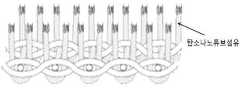
도 1은 탄소나노튜브 섬유를 이용한 벨벳직물을 나타낸 것이다.
도 2는 본 발명에서의 실시예3에 의해서 제조된 벨벳형 전계전자방출 소자의 I-V커브를 나타낸 것이다. Turn-On 값(전압/간격) : 0.1V/micron.
도 3은 본원발명의 발광모습을 촬영한 이미지이다.
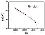
도 4는 본 발명에서의 실시예3에서 제조된 벨벳형 전계전자방출 소자의 Fowler-Nordheim 그래프이다. 직선형을 나타내는 것으로부터 전계전자방출 소자의 성질을 나타낸다고 할 수 있다.
도 5는 금속메쉬 기판에 제조된 탄소나노튜브섬유 전계전자방출 소자를 촬영한 이미지이다.
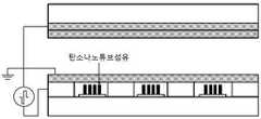
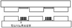
도 6은 탄소나노튜브 섬유를 3극관형 전계전자방출소자에 적용한 단면도를 나타낸 것이다.
도 7은 탄소나노튜브 섬유를 2극관형 전계전자방출소자에 적용한 단면도를 나타낸 것이다.Figure 1 shows a velvet fabric using carbon nanotube fibers.
Figure 2 shows the IV curve of the velvet-type field emission device produced by Example 3 in the present invention. Turn-On value (voltage / spacing): 0.1V / micron.
Figure 3 is an image of the emission form of the present invention.
4 is a Fowler-Nordheim graph of the velvet-type field emission device manufactured in Example 3 of the present invention. It can be said that the property of the field electron emission element is shown from showing a linear form.
5 is an image of a carbon nanotube fiber field emission device manufactured on a metal mesh substrate.
6 shows a cross-sectional view of carbon nanotube fibers applied to a triode tube field emission device.
7 is a cross-sectional view of carbon nanotube fibers applied to a bipolar tube type field electron emission device.
이하, 실시예를 통하여 본 발명을 더욱 상세히 설명하고자 한다. 이들 실시예는 오로지 본 발명을 보다 구체적으로 설명하기 위한 것으로, 본 발명의 요지에 따라 본 발명의 범위가 이들 실시예에 의해 제한되지 않는다는 것은 당업계에서 통상의 지식을 가진 자에 있어서 자명할 것이다.
Hereinafter, the present invention will be described in more detail with reference to Examples. It is to be understood by those skilled in the art that these embodiments are only for describing the present invention in more detail and that the scope of the present invention is not limited by these embodiments in accordance with the gist of the present invention .
실시예Example
본 명세서 전체에 걸쳐, 특정 물질의 농도를 나타내기 위하여 사용되는 “%“는 별도의 언급이 없는 경우, 고체/고체는 (중량/중량) %, 고체/액체는 (중량/부피) %, 그리고 액체/액체는 (부피/부피) %이다.
Throughout this specification, "%" used to denote the concentration of a particular substance is intended to include solids / solids (wt / wt), solid / liquid (wt / The liquid / liquid is (vol / vol)%.
실시예 1: 탄소나노튜브 섬유를 이용한 벨벳 직물 제조Example 1 Preparation of Velvet Fabric Using Carbon Nanotube Fiber
촉매로 페로센(ferrocene) 2.3 wt%, 활성제로 싸이오펜(thiophene) 1.5 wt% 비율로 탄소공급원인 아세톤(acetone)과 혼합하여 초음파처리 장치로 분산시킨 용액과 수소가스를 800 ㎖/분의 속도로 함께 전기로에 투입하였다. 이때 전기로의 온도는 1,100℃로 하여 탄소나노튜브 섬유를 합성하였다.At a rate of 800 ml / min, the solution and hydrogen gas were mixed with acetone, a carbon source, at a rate of 2.3 wt% ferrocene as a catalyst and 1.5 wt% thiophene as an activator. Put together in the electric furnace. At this time, the temperature of the electric furnace was 1,100 ℃ synthesized carbon nanotube fibers.
그 다음, 탄소나노튜브 섬유를 이용하여 벨벳을 제조하였으며, 벨벳은 조직상의 날실(a structural warp), 조직상의 씨실(a structural weft), 보조적인 날실(a supplementary warp) 등 세 가지 요소로 이루어져 직조 과정 중에 막대(rods)나 줄(wire)을 삽입하여 날실을 일으켜 파일을 만들어 내는 고대의 직조방식으로 직조하였다.Then, the velvet was manufactured using carbon nanotube fibers, and the velvet was composed of three elements: a structural warp, a structural weft, and a supplementary warp. During the process, rods or wires were inserted to weave in ancient weaving methods, producing warps to produce piles.
본 실시예를 통하여 제조된 탄소나노튜브 섬유를 이용한 벨벳 직물을 도 1에 나타내었다. 또한, 벨벳 직물을 탄소나노튜브 섬유를 이용하여 제조할 경우 탄소나노튜브의 선단에서부터 전자가 방출되도록 할 수 있으며, 탄소나노튜브 선단이 다양한 패턴을 갖도록 배열 할 수 있게 된다.
The velvet fabric using the carbon nanotube fibers produced through the present example is shown in FIG. In addition, when the velvet fabric is manufactured using carbon nanotube fibers, electrons may be emitted from the ends of the carbon nanotubes, and the carbon nanotube ends may be arranged to have various patterns.
실시예 2: 이중 직물로 직조하는 방법을 이용한 벨벳 직물 제조Example 2 Preparation of Velvet Fabric Using a Weaving Method with Double Fabrics
상기 실시예 1과 동일한 방법으로 제조된 탄소나노튜브 섬유를 이중직물로 직조한 후 그 가운데를 칼날로 절단하여서 표면에 파일이 있는 두 장의 직물을 얻었다.
Carbon nanotube fibers prepared in the same manner as in Example 1 was woven into a double fabric and then cut in the middle with a blade to obtain two fabrics with piles on the surface.
실시예 3: 매쉬를 이용한 벨벳 직물 제조Example 3: Velvet Fabric Preparation Using Mesh
작은 구멍이 일정한 크기로 뚫려있는 메쉬(mesh)에 상기 실시예 1과 동일한 방법으로 제조된 탄소나노튜브 섬유를 바느질 하듯이 배열한 후 한쪽면의 섬유를 절단하여 탄소나노튜브의 선단이 노출되게 되게 하였다(도 3).
After arranging the carbon nanotube fibers manufactured in the same manner as in Example 1 to a mesh in which small holes are drilled to a predetermined size, the fibers of one side are cut to expose the ends of the carbon nanotubes. (FIG. 3).
이상으로 본 발명의 특정한 부분을 상세히 기술하였는바, 당업계의 통상의 지식을 가진 자에게 있어서 이러한 구체적인 기술은 단지 바람직한 구현예일 뿐이며, 이에 본 발명의 범위가 제한되는 것이 아닌 점은 명백하다. 따라서 본 발명의 실질적인 범위는 첨부된 청구항과 그의 등가물에 의하여 정의된다고 할 것이다.
While the present invention has been particularly shown and described with reference to exemplary embodiments thereof, it is to be understood that the same is by way of illustration and example only and is not to be construed as limiting the scope of the present invention. Therefore, the substantial scope of the present invention will be defined by the appended claims and equivalents thereof.
Claims (15)
Translated fromKorean상기 소자에서 방출될 전자의 이동 방향과 실질적으로 평행하지 않은 평면 상에 탄소나노튜브 섬유로 직조한 벨벳 직물이 위치하되,
이 벨벳 직물을 이루고 있는 루프를 절단하여 형성되는 탄소나노튜브 섬유 선단이 상기 평면에 대하여 파일(pile) 형태로 세워지며,
이 탄소나노튜브 섬유 선단으로부터 전자가 방출되는 것을 특징으로 하는, 벨벳형 전계전자방출 소자.
In the field electron emission device,
A velvet fabric woven from carbon nanotube fibers is placed on a plane that is not substantially parallel to the direction of movement of electrons to be emitted from the device,
The carbon nanotube fiber tip formed by cutting the loops forming the velvet fabric is erected in the form of a pile with respect to the plane.
A velvet type field emission device, characterized in that electrons are emitted from the carbon nanotube fiber tip.
상기 소자에서 방출될 전자의 이동 방향과 실질적으로 평행하지 않은 평면 상에 기판이 위치하고,
이 기판 상에는, 벨벳 형상으로 설치된 탄소나노튜브 섬유 선단이 상기 평면에 대하여 파일(pile) 형태로 세워지며,
이 탄소나노튜브 섬유 선단으로부터 전자가 방출되는 것을 특징으로 하는, 벨벳형 전계전자방출 소자.
In the field electron emission device,
The substrate is located on a plane that is not substantially parallel to the direction of movement of electrons to be emitted from the device,
On this substrate, a carbon nanotube fiber tip installed in a velvet shape is erected in the form of a pile with respect to the plane.
A velvet type field emission device, characterized in that electrons are emitted from the carbon nanotube fiber tip.
The method of claim 1 or 2, wherein the carbon nanotubes are multi-wall carbon nanotubes, single-walled carbon nanotubes, and double-walled carbon nanotubes. Velvet-type field electron emission device, characterized in that at least one carbon nanotube selected from the group consisting of.
The velvet-type field emission device as claimed in claim 1, wherein the fabric is a fabric manufactured by a velvet weaving method or a double fabric weaving method.
The velvet type field emission device according to claim 1 or 2, wherein the carbon nanotube fiber tip is a pile of carbon nanotube fibers in the form of piles erected in a direction of 60-120 ° with respect to the plane.
The velvet-type field emission device of claim 1 or 2, wherein the velvet-shaped carbon nanotube fiber tip is a velvet-free carbon nanotube fiber tip without a node.
The velvet-type field emission device of claim 2, wherein the substrate is a mesh, a nonwoven fabric, a fabric, a film, or a glass.
9. The velvet type field emission device according to claim 8, wherein the mesh is a mesh made of metal or fiber.
(a) 탄소나노튜브 섬유를 이용하여 직물을 직조, 또는 기판에 탄소나노튜브 섬유로 파일(pile)을 제조하는 단계; 및
(b) 상기 제조된 직물 또는 파일에 벨벳 형태의 탄소나노튜브 섬유 선단을 형성시키는 단계를 포함하는 벨벳형 전계전자방출 소자 제조방법.
A method of manufacturing a velvet-type field emission device including a velvet-shaped carbon nanotube fiber tip,
(a) weaving a fabric using carbon nanotube fibers, or preparing a pile of carbon nanotube fibers on a substrate; And
(B) a velvet-type field emission device manufacturing method comprising the step of forming a carbon nanotube fiber tip of the velvet form on the fabric or pile.
The method of claim 10, wherein in step (a), the carbon nanotubes are multi-wall carbon nanotubes, single-walled carbon nanotubes, and double-walled carbon nanotubes. Carbon nanotube) Velvet-type field emission device manufacturing method characterized in that the at least one carbon nanotube selected from the group consisting of.
The method of claim 10, wherein the substrate is a mesh, a nonwoven fabric, a fabric, a film, or a glass.
13. The method of claim 12, wherein the mesh is a mesh made of metal or fiber.
The velvet-type electric field of claim 10, wherein the velvet-shaped carbon nanotube fiber tip in step (b) is a velvet-shaped carbon nanotube fiber tip having a direction of 60-120 ° with respect to the direction of the substrate. Electron-emitting device manufacturing method.
Priority Applications (2)
| Application Number | Priority Date | Filing Date | Title |
|---|---|---|---|
| KR1020110025545AKR101162881B1 (en) | 2011-03-22 | 2011-03-22 | Velvety field electron emitter comprising velvet-shaped carbon nanotube fibers top end and manufacturing methods thereof |
| PCT/KR2011/007862WO2012128437A1 (en) | 2011-03-22 | 2011-10-20 | Velvety field electron emitting device including velvet-shaped carbon nanotube fiber top end, and method for manufacturing same |
Applications Claiming Priority (1)
| Application Number | Priority Date | Filing Date | Title |
|---|---|---|---|
| KR1020110025545AKR101162881B1 (en) | 2011-03-22 | 2011-03-22 | Velvety field electron emitter comprising velvet-shaped carbon nanotube fibers top end and manufacturing methods thereof |
Publications (1)
| Publication Number | Publication Date |
|---|---|
| KR101162881B1true KR101162881B1 (en) | 2012-07-05 |
Family
ID=46716307
Family Applications (1)
| Application Number | Title | Priority Date | Filing Date |
|---|---|---|---|
| KR1020110025545AExpired - Fee RelatedKR101162881B1 (en) | 2011-03-22 | 2011-03-22 | Velvety field electron emitter comprising velvet-shaped carbon nanotube fibers top end and manufacturing methods thereof |
Country Status (2)
| Country | Link |
|---|---|
| KR (1) | KR101162881B1 (en) |
| WO (1) | WO2012128437A1 (en) |
Cited By (2)
| Publication number | Priority date | Publication date | Assignee | Title |
|---|---|---|---|---|
| KR102536324B1 (en)* | 2021-12-30 | 2023-05-26 | 어썸레이 주식회사 | Ultraviolet ray emitting device |
| US11913146B1 (en)* | 2019-07-18 | 2024-02-27 | United States Of America As Represented By The Secretary Of The Air Force | Carbon nanotube yarn cathode using textile manufacturing methods |
Family Cites Families (1)
| Publication number | Priority date | Publication date | Assignee | Title |
|---|---|---|---|---|
| CN105696139B (en)* | 2004-11-09 | 2019-04-16 | 得克萨斯大学体系董事会 | The manufacture and application of nano-fibre yams, band and plate |
- 2011
- 2011-03-22KRKR1020110025545Apatent/KR101162881B1/ennot_activeExpired - Fee Related
- 2011-10-20WOPCT/KR2011/007862patent/WO2012128437A1/enactiveApplication Filing
Cited By (5)
| Publication number | Priority date | Publication date | Assignee | Title |
|---|---|---|---|---|
| US11913146B1 (en)* | 2019-07-18 | 2024-02-27 | United States Of America As Represented By The Secretary Of The Air Force | Carbon nanotube yarn cathode using textile manufacturing methods |
| KR102536324B1 (en)* | 2021-12-30 | 2023-05-26 | 어썸레이 주식회사 | Ultraviolet ray emitting device |
| WO2023128022A1 (en)* | 2021-12-30 | 2023-07-06 | 어썸레이 주식회사 | Ultraviolet emitting device |
| US12020921B2 (en) | 2021-12-30 | 2024-06-25 | Awexome Ray, Inc. | Ultraviolet ray emitting device |
| TWI859684B (en)* | 2021-12-30 | 2024-10-21 | 南韓商奧爽樂股份有限公司 | Ultraviolet ray emitting device |
Also Published As
| Publication number | Publication date |
|---|---|
| WO2012128437A1 (en) | 2012-09-27 |
Similar Documents
| Publication | Publication Date | Title |
|---|---|---|
| Lee et al. | High-performance field emission from a carbon nanotube carpet | |
| US8193692B2 (en) | Surface field electron emitters using carbon nanotube yarn and method of fabricating carbon nanotube yarn thereof | |
| Pan et al. | Field emission properties of carbon tubule nanocoils | |
| Shin et al. | High performance field emission of carbon nanotube film emitters with a triangular shape | |
| JP2009231287A (en) | Carbon nanotube needle and manufacturing method of the same | |
| US7914358B2 (en) | Method for manufacturing field emission electron source having carbon nanotubes | |
| JP2002179418A (en) | How to make carbon nanotubes | |
| US20090117674A1 (en) | Method for manufacturing field emission electron source having carbon nanotubes | |
| KR20110063501A (en) | Nanocarbon Material Composite Substrate and Manufacturing Method Thereof | |
| Ci et al. | Multifunctional Macroarchitectures of Double‐Walled Carbon Nanotube Fibers | |
| US8029328B2 (en) | Method for manufacturing field emission electron source having carbon nanotubes | |
| KR101162881B1 (en) | Velvety field electron emitter comprising velvet-shaped carbon nanotube fibers top end and manufacturing methods thereof | |
| Li et al. | High-performance field emitters based on SiC nanowires with designed electron emission sites | |
| JP4913791B2 (en) | Field emission electron source and manufacturing method thereof | |
| KR101387700B1 (en) | Field emission apparatus having bundle structure of carbon nano tube based emitters | |
| DE602004005848T2 (en) | CATHODE FOR AN ELECTRON SOURCE | |
| KR101342356B1 (en) | Method for producing carbon film using plasma cvd and carbon film | |
| Jang et al. | Field emission properties from the tip and side of multi-walled carbon nanotube yarns | |
| US20090134127A1 (en) | Electron beam heating system having carbon nanotubes | |
| CN100370571C (en) | Field emission cathodes and field emission devices | |
| US7781954B2 (en) | Pixel element for field emission display | |
| KR101227258B1 (en) | Triode cold cathode electron source for x-ray generation using array of multiple carbon nano-tube tips | |
| KR102581259B1 (en) | X-ray Tube containing an emitter in which a vine-shaped carbon nano structure is formed | |
| KR102581290B1 (en) | An electron microscope containing an electron gun in which a vine-shaped carbon nano structure is formed | |
| CN220787698U (en) | Breathable wire winding tube |
Legal Events
| Date | Code | Title | Description |
|---|---|---|---|
| A201 | Request for examination | ||
| PA0109 | Patent application | St.27 status event code:A-0-1-A10-A12-nap-PA0109 | |
| PA0201 | Request for examination | St.27 status event code:A-1-2-D10-D11-exm-PA0201 | |
| P11-X000 | Amendment of application requested | St.27 status event code:A-2-2-P10-P11-nap-X000 | |
| P13-X000 | Application amended | St.27 status event code:A-2-2-P10-P13-nap-X000 | |
| PE0902 | Notice of grounds for rejection | St.27 status event code:A-1-2-D10-D21-exm-PE0902 | |
| E13-X000 | Pre-grant limitation requested | St.27 status event code:A-2-3-E10-E13-lim-X000 | |
| P11-X000 | Amendment of application requested | St.27 status event code:A-2-2-P10-P11-nap-X000 | |
| P13-X000 | Application amended | St.27 status event code:A-2-2-P10-P13-nap-X000 | |
| E701 | Decision to grant or registration of patent right | ||
| PE0701 | Decision of registration | St.27 status event code:A-1-2-D10-D22-exm-PE0701 | |
| GRNT | Written decision to grant | ||
| PR0701 | Registration of establishment | St.27 status event code:A-2-4-F10-F11-exm-PR0701 | |
| PR1002 | Payment of registration fee | St.27 status event code:A-2-2-U10-U11-oth-PR1002 Fee payment year number:1 | |
| PG1601 | Publication of registration | St.27 status event code:A-4-4-Q10-Q13-nap-PG1601 | |
| PR1001 | Payment of annual fee | St.27 status event code:A-4-4-U10-U11-oth-PR1001 Fee payment year number:4 | |
| PR1001 | Payment of annual fee | St.27 status event code:A-4-4-U10-U11-oth-PR1001 Fee payment year number:5 | |
| PN2301 | Change of applicant | St.27 status event code:A-5-5-R10-R13-asn-PN2301 St.27 status event code:A-5-5-R10-R11-asn-PN2301 | |
| P22-X000 | Classification modified | St.27 status event code:A-4-4-P10-P22-nap-X000 | |
| FPAY | Annual fee payment | Payment date:20170410 Year of fee payment:6 | |
| PR1001 | Payment of annual fee | St.27 status event code:A-4-4-U10-U11-oth-PR1001 Fee payment year number:6 | |
| LAPS | Lapse due to unpaid annual fee | ||
| PC1903 | Unpaid annual fee | St.27 status event code:A-4-4-U10-U13-oth-PC1903 Not in force date:20180629 Payment event data comment text:Termination Category : DEFAULT_OF_REGISTRATION_FEE | |
| PC1903 | Unpaid annual fee | St.27 status event code:N-4-6-H10-H13-oth-PC1903 Ip right cessation event data comment text:Termination Category : DEFAULT_OF_REGISTRATION_FEE Not in force date:20180629 | |
| PN2301 | Change of applicant | St.27 status event code:A-5-5-R10-R13-asn-PN2301 St.27 status event code:A-5-5-R10-R11-asn-PN2301 |