KR101156736B1 - The radiating heat module for LED fish-luring lamp - Google Patents
The radiating heat module for LED fish-luring lampDownload PDFInfo
- Publication number
- KR101156736B1 KR101156736B1KR1020100015802AKR20100015802AKR101156736B1KR 101156736 B1KR101156736 B1KR 101156736B1KR 1020100015802 AKR1020100015802 AKR 1020100015802AKR 20100015802 AKR20100015802 AKR 20100015802AKR 101156736 B1KR101156736 B1KR 101156736B1
- Authority
- KR
- South Korea
- Prior art keywords
- led
- heat
- heat pipe
- heat dissipation
- light source
- Prior art date
- Legal status (The legal status is an assumption and is not a legal conclusion. Google has not performed a legal analysis and makes no representation as to the accuracy of the status listed.)
- Active
Links
- 230000017525heat dissipationEffects0.000claimsabstractdescription21
- CSCPPACGZOOCGX-UHFFFAOYSA-NAcetoneChemical compoundCC(C)=OCSCPPACGZOOCGX-UHFFFAOYSA-N0.000claimsdescription6
- 239000002826coolantSubstances0.000claimsdescription5
- 238000000034methodMethods0.000claimsdescription3
- 230000020169heat generationEffects0.000abstractdescription4
- 239000003507refrigerantSubstances0.000description6
- 238000005192partitionMethods0.000description3
- 239000004065semiconductorSubstances0.000description3
- JBRZTFJDHDCESZ-UHFFFAOYSA-NAsGaChemical compound[As]#[Ga]JBRZTFJDHDCESZ-UHFFFAOYSA-N0.000description2
- 229910005540GaPInorganic materials0.000description2
- 230000000694effectsEffects0.000description2
- 238000004020luminiscence typeMethods0.000description2
- 239000000463materialSubstances0.000description2
- 229910052698phosphorusInorganic materials0.000description2
- 239000011574phosphorusSubstances0.000description2
- 229910001218Gallium arsenideInorganic materials0.000description1
- GPXJNWSHGFTCBW-UHFFFAOYSA-NIndium phosphideChemical compound[In]#PGPXJNWSHGFTCBW-UHFFFAOYSA-N0.000description1
- 239000000853adhesiveSubstances0.000description1
- 230000001070adhesive effectEffects0.000description1
- 239000002390adhesive tapeSubstances0.000description1
- 229910052782aluminiumInorganic materials0.000description1
- XAGFODPZIPBFFR-UHFFFAOYSA-NaluminiumChemical compound[Al]XAGFODPZIPBFFR-UHFFFAOYSA-N0.000description1
- 238000005452bendingMethods0.000description1
- 239000000969carrierSubstances0.000description1
- 150000001875compoundsChemical class0.000description1
- 238000001816coolingMethods0.000description1
- 239000013078crystalSubstances0.000description1
- 230000005684electric fieldEffects0.000description1
- HZXMRANICFIONG-UHFFFAOYSA-Ngallium phosphideChemical compound[Ga]#PHZXMRANICFIONG-UHFFFAOYSA-N0.000description1
- 230000010354integrationEffects0.000description1
- 229910001507metal halideInorganic materials0.000description1
- 150000005309metal halidesChemical class0.000description1
- 230000002250progressing effectEffects0.000description1
- 230000005855radiationEffects0.000description1
- 230000006798recombinationEffects0.000description1
- 238000005215recombinationMethods0.000description1
- HBMJWWWQQXIZIP-UHFFFAOYSA-Nsilicon carbideChemical compound[Si+]#[C-]HBMJWWWQQXIZIP-UHFFFAOYSA-N0.000description1
- 229910010271silicon carbideInorganic materials0.000description1
Images

Classifications
- A—HUMAN NECESSITIES
- A01—AGRICULTURE; FORESTRY; ANIMAL HUSBANDRY; HUNTING; TRAPPING; FISHING
- A01K—ANIMAL HUSBANDRY; AVICULTURE; APICULTURE; PISCICULTURE; FISHING; REARING OR BREEDING ANIMALS, NOT OTHERWISE PROVIDED FOR; NEW BREEDS OF ANIMALS
- A01K79/00—Methods or means of catching fish in bulk not provided for in groups A01K69/00 - A01K77/00, e.g. fish pumps; Detection of fish; Whale fishery
- F—MECHANICAL ENGINEERING; LIGHTING; HEATING; WEAPONS; BLASTING
- F21—LIGHTING
- F21V—FUNCTIONAL FEATURES OR DETAILS OF LIGHTING DEVICES OR SYSTEMS THEREOF; STRUCTURAL COMBINATIONS OF LIGHTING DEVICES WITH OTHER ARTICLES, NOT OTHERWISE PROVIDED FOR
- F21V29/00—Protecting lighting devices from thermal damage; Cooling or heating arrangements specially adapted for lighting devices or systems
- F21V29/50—Cooling arrangements
- F21V29/51—Cooling arrangements using condensation or evaporation of a fluid, e.g. heat pipes
- F—MECHANICAL ENGINEERING; LIGHTING; HEATING; WEAPONS; BLASTING
- F21—LIGHTING
- F21V—FUNCTIONAL FEATURES OR DETAILS OF LIGHTING DEVICES OR SYSTEMS THEREOF; STRUCTURAL COMBINATIONS OF LIGHTING DEVICES WITH OTHER ARTICLES, NOT OTHERWISE PROVIDED FOR
- F21V29/00—Protecting lighting devices from thermal damage; Cooling or heating arrangements specially adapted for lighting devices or systems
- F21V29/50—Cooling arrangements
- F21V29/56—Cooling arrangements using liquid coolants
- F21V29/58—Cooling arrangements using liquid coolants characterised by the coolants
- F—MECHANICAL ENGINEERING; LIGHTING; HEATING; WEAPONS; BLASTING
- F21—LIGHTING
- F21V—FUNCTIONAL FEATURES OR DETAILS OF LIGHTING DEVICES OR SYSTEMS THEREOF; STRUCTURAL COMBINATIONS OF LIGHTING DEVICES WITH OTHER ARTICLES, NOT OTHERWISE PROVIDED FOR
- F21V29/00—Protecting lighting devices from thermal damage; Cooling or heating arrangements specially adapted for lighting devices or systems
- F21V29/50—Cooling arrangements
- F21V29/70—Cooling arrangements characterised by passive heat-dissipating elements, e.g. heat-sinks
- F21V29/71—Cooling arrangements characterised by passive heat-dissipating elements, e.g. heat-sinks using a combination of separate elements interconnected by heat-conducting means, e.g. with heat pipes or thermally conductive bars between separate heat-sink elements
- F—MECHANICAL ENGINEERING; LIGHTING; HEATING; WEAPONS; BLASTING
- F21—LIGHTING
- F21Y—INDEXING SCHEME ASSOCIATED WITH SUBCLASSES F21K, F21L, F21S and F21V, RELATING TO THE FORM OR THE KIND OF THE LIGHT SOURCES OR OF THE COLOUR OF THE LIGHT EMITTED
- F21Y2115/00—Light-generating elements of semiconductor light sources
- F21Y2115/10—Light-emitting diodes [LED]
Landscapes
- Engineering & Computer Science (AREA)
- General Engineering & Computer Science (AREA)
- Life Sciences & Earth Sciences (AREA)
- Environmental Sciences (AREA)
- Marine Sciences & Fisheries (AREA)
- Animal Husbandry (AREA)
- Biodiversity & Conservation Biology (AREA)
- Cooling Or The Like Of Semiconductors Or Solid State Devices (AREA)
- Arrangement Of Elements, Cooling, Sealing, Or The Like Of Lighting Devices (AREA)
Abstract
Translated fromKorean
Description
Translated fromKorean본 발명은 어선에서 사용되고 있는 LED 집어등용 방열 모듈에 관한 것으로, 상세하게는 U자 형태의 평판 히트 파이프에 방열 면적을 높이는 히트 싱크를 결합하여, 발열 효율이 향상되고 경량화가 이루어진 LED 집어등용 방열 모듈에 관한 것이다.The present invention relates to a heat dissipation module for LED fishing lamps used in fishing vessels, and more specifically, to a heat sink for LED fishing lamps in which a heat sink for increasing heat dissipation is combined with a U-shaped flat heat pipe, thereby improving heat generation efficiency and reducing weight. It is about.
최근 들어, 세계 각국이 녹색성장에 초점을 맞추면서 에너지를 절감하는 친환경적인 LED(luminescent diode)가 광원으로 각광받고 있다. LED는 기존 광원에 비하여 낮은 전력 소모량과 긴 수명, 작은 크기 등의 장점을 가지며, LCD의 백라이트, 전광판, 형광등, 자동차용 브레이크나 방향지시등, 가로등, 각종 전자제품 표시등, 선박이나 항공기 점멸등에 다양하게 활용되고 있다.Recently, eco-friendly LEDs (luminescent diodes) that save energy while focusing on green growth have been spotlighted as light sources. LED has the advantages of low power consumption, long life, and small size compared to existing light sources, and is diverse in backlight of LCD, electronic board, fluorescent lamp, automobile brake or direction indicator, street lamp, various electronic product indicator, ship or aircraft flickering light. It is utilized.
이러한 종래의 조명용 LED에서는 많은 전류량에 의하여 높은 열이 발생하며, 이 발생된 열에 의하여 패널 전체의 온도가 상승하게 되고 이로 인하여 여러 가지 문제점이 발생하게 된다. 따라서 LED에서 방출된 열을 신속하고 효율적으로 냉각시키기 위하여, LED의 일 측에는 히트 싱크(heat sink)가 구비되는 것이 일반적이었다.In such a conventional lighting LED, high heat is generated by a large amount of current, and the temperature of the entire panel is increased by the generated heat, which causes various problems. Therefore, in order to cool the heat emitted from the LED quickly and efficiently, it was common to have a heat sink on one side of the LED.
이와 같은 종래의 조명용 LED용 히트 싱크의 경우, 나란하게 배치된 하나 이상의 프레임 각각으로부터 다수 개의 방열핀이 가지 형태로 돌출 형성된 구조로 이루어졌다. 그런데, 이와 같은 종래의 LED용 히트 싱크의 경우, 조명용 LED에서와 같이 높은 열이 발생하지 않았기 때문에 독립적인 형태의 히트 싱크의 구조만으로 방열의 문제를 해결할 수 있었다. 그러나, 집어등에서 사용되는 조명용 LED의 경우, 기존의 메탈할라이드(Metal Halide) 조명을 대체할 목적으로 소형화 고출력을 이용하기 때문에, LED소자의 고집적도가 요구되어 일반적인 방열설계로는 성능을 발휘하지 못한다는 문제점이 존재하였다.In the conventional heat sink for LED lighting, a plurality of heat dissipation fins are formed to protrude in a branch form from each of one or more frames arranged side by side. However, in the conventional heat sink for LED, since high heat does not occur as in the lighting LED, the problem of heat dissipation could be solved only by the structure of the independent heat sink. However, in the case of a lighting LED used in a fishing lamp, because it uses a miniaturized high output for the purpose of replacing the existing metal halide lighting, the high integration degree of the LED device is required, and thus the heat dissipation design does not show the performance. There was a problem.
본 발명은 상기와 같은 종래의 문제점을 극복하기 위한 것으로, 발열 효율이 향상되고 경량화가 이루어진 LED 집어등용 방열 모듈을 제공하는 것을 목적으로 한다.The present invention is to overcome the conventional problems as described above, and an object of the present invention is to provide a heat dissipation module for LED pick-up lamp that the heat generation efficiency is improved and reduced in weight.
본 발명은 LED(luminescent diode) 집어등 광원; 상기 LED 집어등 광원에서 광이 출사되는 면과 대향되는 측에 결합하는 평판 히트 파이프(Plate Heat pipe); 및 상기 평판 히트 파이프에 끼워지는 하나 이상의 히트 싱크(Heat sink)를 포함하는 LED 집어등용 방열 모듈을 제공한다.The present invention is an LED (luminescent diode) pick-up light source; A plate heat pipe coupled to a side opposite to a surface from which the light is emitted from the LED light source; And one or more heat sinks fitted to the flat heat pipes.
본 발명에 있어서, 상기 평판 히트 파이프는 대략 "U"자 형상으로 형성되고, 상기 히트 싱크는 다수 개의 형성된 평판 형상으로 형성되며, 상기 히트 싱크는 상기 평판 히트 파이프에 끼워질 수 있다.In the present invention, the plate heat pipe is formed in a substantially "U" shape, the heat sink is formed in a plurality of formed plate shape, the heat sink can be fitted to the plate heat pipe.
본 발명에 있어서, 상기 평판 히트 파이프의 내부에는 냉매가 충전되며, 상기 냉매는 상기 평판 히트 파이프 내부에서 유동할 수 있다.In the present invention, a refrigerant is filled in the flat heat pipe, and the coolant may flow in the flat heat pipe.
여기서, 상기 냉매는 아세톤을 포함할 수 있다.Here, the refrigerant may include acetone.
본 발명에 따른 LED 집어등용 방열 모듈에 의하여, 발열 효율이 향상되고 경량화가 이루어지는 효과를 얻을 수 있다.By the heat dissipation module for LED pick lamps according to the present invention, it is possible to obtain the effect that the heat generation efficiency is improved and the weight is reduced.
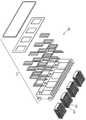
도 1은 본 발명의 일 실시 예에 관한 LED용 히트 싱크를 나타내는 분해 사시도.
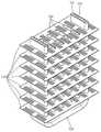
도 2는 도 1의 LED용 히트 싱크의 조립 사시도.
도 3은 도 1의 LED용 히트 싱크의 프레임과 브리지 부분을 상세하게 나타낸 사시도.1 is an exploded perspective view showing a heat sink for LED according to an embodiment of the present invention.
FIG. 2 is an assembled perspective view of the heat sink for LED of FIG. 1. FIG.
Figure 3 is a perspective view showing in detail the frame and the bridge portion of the heat sink for LED of Figure 1;
이하, 첨부된 도면을 참조하여 본 발명을 상세히 설명한다.Hereinafter, with reference to the accompanying drawings will be described in detail the present invention.
도 1은 본 발명의 일 실시예에 관한 LED 집어등용 방열 모듈을 나타내는 분해 사시도이고, 도 2는 도 1의 LED 집어등용 방열 모듈의 조립 사시도이고, 도 3은 도 1의 LED 집어등용 방열 모듈의 평판 히트 파이프와 히트 싱크 부분을 상세하게 나타낸 사시도이다.1 is an exploded perspective view illustrating a heat dissipation module for an LED catcher according to an embodiment of the present invention, FIG. 2 is an assembled perspective view of the heat dissipation module for an LED catcher of FIG. 1, and FIG. 3 is a heat dissipation module for the LED catcher of FIG. 1. It is a perspective view which shows the flat plate heat pipe and a heat sink part in detail.
도 1 내지 도 3을 참조하면, 본 발명의 일 실시예에 관한 LED 집어등용 방열 모듈(100)은 LED 집어등 광원(110)과 평판 히트 파이프(Plate heat pipe)(120)와 브리지(bridge)(130)를 포함한다.1 to 3, the
LED 집어등 광원(110)은 소정의 광을 발생시킨다. 상세히, LED(luminescent diode 또는 light emitting diode)는 반도체의 p-n 접합구조를 이용하여 주입된 소수 캐리어(전자 또는 정공)를 만들어내고, 이들의 재결합에 의하여 발광시키는 장치를 의미한다. 반도체에 전압을 가할 때 생기는 발광 현상은 전기 루미네선스(전기장발광)라고 하며, 1923년 탄화규소 결정의 발광 관측에서 비롯된다. 1923년에 비소화갈륨 p-n 접합에서의 고발광효율이 발견되면서부터 그 연구가 활발하게 진행되었고, 1960년대 말에는 이들이 실용화되기에 이르렀다.The LED collecting
발광다이오드에 적합한 재료로는 발광파장이 가시 또는 근적외 영역에 존재할 것, 발광효율이 높을 것, p-n접합의 제작이 가능할 것 등의 조건을 만족시키는 것으로서, 주로 비소화갈륨(GaAs), 인화갈륨(GaP), 갈륨-비소-인(GaAs1-x Px), 갈륨-알루미늄-비소(Ga1-xAlxAs), 인화인듐(InP), 인듐-갈륨-인(ln1-xGaxP) 등 3B 및 5B족인 2원소 또는 3원소 화합물 반도체가 사용되고 있는데, 2B, 6B족이나 4A, 4B족인 것에 대하여도 연구가 진행되고 있다.Suitable materials for light emitting diodes satisfy the conditions such that the light emission wavelength is present in the visible or near-infrared region, the light emission efficiency is high, and the pn junction can be manufactured. Gallium arsenide (GaAs) and gallium phosphide are mainly used. (GaP), gallium-arsenic-phosphorus (GaAs1-x Px), gallium-aluminum-arsenic (Ga1-xAlxAs), indium phosphide (InP), indium-gallium-phosphorus (ln1-xGaxP), etc. Or although a three-element compound semiconductor is used, the research is also progressing about 2B, 6B group, 4A, and 4B group.
이와 같은 LED 집어등 광원(110)은 기 공지된 기술이므로 본 명세서에서는 그 상세한 설명은 생략한다.Since the LED pick-
평판 히트 파이프(120)는 복수 개가 구비되며, 상기 LED 집어등 광원(110)에서 광이 출사되는 면과 대향되는 측에 결합된다. 상기 평판 히트 파이프 (120)는 본드 또는 접착 테이프 등의 접착 부재(미도시)에 의하여 LED 집어등 광원(110)의 일 면에 결합될 수 있다.A plurality of flat
평판 히트 파이프(120)는 대략 "U"자 형상의 파이프 형태로 형성된다. 여기서, 평판 히트 파이프(120)는 세 개의 파이프 부재를 결합하여 형성될 수도 있고, 하나의 파이프 부재를 절곡하여 형성될 수도 있다. 한편, 평판 히트 파이프(120) 내부의 중공부(121)에는 하나 이상의 격벽(122)이 형성될 수도 있다.The
한편, 평판 히트 파이프(120) 내부의 중공부(121), 상세하게는 중공부(121)의 격벽(122) 사이사이에는 냉매가 충전될 수 있다. 이 냉매는 상기 평판 히트 파이프(120) 내부를 유동하면서 히트 싱크의 냉각 성능을 향상시키는 역할을 수행한다. 이와 같은 냉매로는 아세톤(acetone) 등이 사용될 수 있다. 도 3에는 평판 히트 파이프(120)의 양단부가 개방되어 있는 것으로 도시되어 있으나, 평판 히트 파이프(120) 내부에 냉매가 충전될 경우에는 냉매가 외부로 유출되지 아니하도록 평판 히트 파이프(120)의 양단부를 밀봉할 수 있다.Meanwhile, a coolant may be filled between the
히트 싱크(130)는 다수 개의 평판 플레이트(132)를 포함한다. 여기서, 상기 평판 플레이트(132)는 알루미늄(Al)과 같은 재질로 이루어진 얇은 판으로 형성될 수 있다. 평판 히트 파이프(120)에서 뜨거워진 냉매가 평판 히트 파이프(120)에 밀착되어 있는 히트 싱크(130)와 접하면서 공기 중에서 방열면적이 커져서 효과적으로 방열설계를 할 수 있어, 독립적인 열원에 대한 해석이 가능해, 확장이 용이하고, 크기가 작아져서 비용이 감소하며, 제품의 경량화가 구현되는 현저한 효과를 얻을 수 있다. 또한, 방열핀 역할을 하는 평판 플레이트(132)가 길이별로 형성되기 때문에, 평판 플레이트(132)의 개수와 간격 길이를 조절함으로써 방열 면적을 용이하게 확대시킬 수 있고, 따라서 방열 성능이 향상되는 효과를 얻을 수 있다.The
이제까지 본 발명에 대하여 그 바람직한 실시 예들을 중심으로 살펴보았다. 본 발명이 속하는 기술 분야에서 통상의 지식을 가진 자는 본 발명이 본 발명의 본질적인 특성에서 벗어나지 않는 범위에서 변형된 형태로 구현될 수 있음을 이해할 수 있을 것이다. 그러므로 개시된 실시 예들은 한정적인 관점이 아니라 설명적인 관점에서 고려되어야 한다. 본 발명의 범위는 전술한 설명이 아니라 특허청구범위에 나타나 있으며, 그와 동등한 범위 내에 있는 모든 차이점은 본 발명에 포함된 것으로 해석되어야 할 것이다.So far I looked at the center of the preferred embodiment for the present invention. Those skilled in the art will appreciate that the present invention can be implemented in a modified form without departing from the essential features of the present invention. Therefore, the disclosed embodiments should be considered in descriptive sense only and not for purposes of limitation. The scope of the present invention is shown in the claims rather than the foregoing description, and all differences within the scope will be construed as being included in the present invention.
100: LED 집어등용 히트 싱크 110: LED 광원
120: 평판 히트 파이프121: 중공부
122: 격벽130: 히트 싱크
132: 평판 플레이트100: heat sink for LED collecting lamp 110: LED light source
120: flat plate heat pipe 121: hollow part
122: partition 130: heat sink
132: flat plate
Claims (4)
Translated fromKorean상기 LED 집어등 광원에서 광이 출사되는 면과 대향되는 측에 결합하며, "U"자 형상으로 형성된 평판 히트 파이프(Plate Heat pipe); 및
상기 히트 파이프의 일측 단부 및 타측 단부가 각각 관통하는 관통구를 구비하여 상기 히트 파이프의 일측 단부 및 타측 단부에 끼워지며, 평판 형상으로 형성된 하나 이상의 히트 싱크(Heat sink)를 포함하는 LED 집어등용 방열 모듈.LED (luminescent diode) pick-up light source;
A plate heat pipe coupled to a side opposite to a surface from which the light is emitted from the LED light source and formed in a “U” shape; And
Heat dissipation for LED lamps including one or more heat sinks having through-holes through which one end and the other end of the heat pipe pass, respectively, fitted to one end and the other end of the heat pipe and having a flat plate shape. module.
상기 평판 히트 파이프의 내부에는 냉매가 충전되며, 상기 냉매는 상기 평판 히트 파이프 내부에서 유동하는 것을 특징으로 하는 LED 집어등용 방열 모듈.The method of claim 1,
The inside of the flat plate heat pipe is filled with a coolant, the coolant heat dissipation module for LED lamps, characterized in that the flow inside the flat heat pipe.
상기 냉매는 아세톤을 포함하는 것을 특징으로 하는 LED 집어등용 방열 모듈.The method of claim 3, wherein
The coolant heat dissipation module for an LED pick lamp, characterized in that it comprises acetone.
Priority Applications (1)
| Application Number | Priority Date | Filing Date | Title |
|---|---|---|---|
| KR1020100015802AKR101156736B1 (en) | 2010-02-22 | 2010-02-22 | The radiating heat module for LED fish-luring lamp |
Applications Claiming Priority (1)
| Application Number | Priority Date | Filing Date | Title |
|---|---|---|---|
| KR1020100015802AKR101156736B1 (en) | 2010-02-22 | 2010-02-22 | The radiating heat module for LED fish-luring lamp |
Publications (2)
| Publication Number | Publication Date |
|---|---|
| KR20110096381A KR20110096381A (en) | 2011-08-30 |
| KR101156736B1true KR101156736B1 (en) | 2012-06-15 |
Family
ID=44931635
Family Applications (1)
| Application Number | Title | Priority Date | Filing Date |
|---|---|---|---|
| KR1020100015802AActiveKR101156736B1 (en) | 2010-02-22 | 2010-02-22 | The radiating heat module for LED fish-luring lamp |
Country Status (1)
| Country | Link |
|---|---|
| KR (1) | KR101156736B1 (en) |
Cited By (1)
| Publication number | Priority date | Publication date | Assignee | Title |
|---|---|---|---|---|
| KR200474947Y1 (en)* | 2012-08-21 | 2014-10-27 | 주식회사 삼진엘앤디 | Apparatus radiating heat for LED lamp |
Families Citing this family (2)
| Publication number | Priority date | Publication date | Assignee | Title |
|---|---|---|---|---|
| KR101167487B1 (en)* | 2011-12-14 | 2012-07-27 | 이용훈 | The cooling water circulation type heater sink |
| KR101288623B1 (en)* | 2013-02-06 | 2013-07-23 | 주식회사 엠티티 | Cooling apparatus for lighting equipment |
Citations (1)
| Publication number | Priority date | Publication date | Assignee | Title |
|---|---|---|---|---|
| KR20110073130A (en)* | 2009-12-23 | 2011-06-29 | 강주훈 | LED luminaire using heat pipe and sky fin |
- 2010
- 2010-02-22KRKR1020100015802Apatent/KR101156736B1/enactiveActive
Patent Citations (1)
| Publication number | Priority date | Publication date | Assignee | Title |
|---|---|---|---|---|
| KR20110073130A (en)* | 2009-12-23 | 2011-06-29 | 강주훈 | LED luminaire using heat pipe and sky fin |
Cited By (1)
| Publication number | Priority date | Publication date | Assignee | Title |
|---|---|---|---|---|
| KR200474947Y1 (en)* | 2012-08-21 | 2014-10-27 | 주식회사 삼진엘앤디 | Apparatus radiating heat for LED lamp |
Also Published As
| Publication number | Publication date |
|---|---|
| KR20110096381A (en) | 2011-08-30 |
Similar Documents
| Publication | Publication Date | Title |
|---|---|---|
| KR100638047B1 (en) | Liquid crystal display with backlight unit | |
| US20120152490A1 (en) | Fastening type heat-dissipation structure | |
| US8089085B2 (en) | Heat sink base for LEDS | |
| US20100323466A1 (en) | Light emitting diode lamp with phosphor coated relector | |
| KR200476144Y1 (en) | All-angle light emitting element having high heat dissipating efficiency | |
| CN101790800A (en) | Optoelectronic devices with upconverting luminescent media | |
| CN101532657A (en) | Illuminating apparatus | |
| KR101156736B1 (en) | The radiating heat module for LED fish-luring lamp | |
| CN103047553A (en) | High-luminous-efficacy high-power light-emitting diode (LED) panel light | |
| US7722222B2 (en) | LED lamp assembly | |
| US8376587B2 (en) | LED illuminating device and light engine thereof | |
| KR101670685B1 (en) | Lighting emitting diode package | |
| JP2013093169A (en) | Heat sink, and lighting device equipped with the same | |
| Kim et al. | Thermal performance of cooling system for red, green and blue LED light source for rear projection TV | |
| RU56558U1 (en) | LED MATRIX COOLING DEVICE | |
| JP6042619B2 (en) | Heat sink and lighting device including the same | |
| Vairavan et al. | 5mm x 5mm copper-diamond composite slug stress evaluation on LED | |
| TWM449906U (en) | LED lamp having heat dissipation structure | |
| JP2013229396A (en) | Heat sink and luminaire including the same | |
| CN220471547U (en) | Radiating assembly of light source module | |
| CN109282168B (en) | A system for obtaining a high lumen density green light source | |
| CN101329056A (en) | High-power and high-brightness street lamp with self-radiation | |
| Li et al. | Effect of junction temperature on the performance of high-power white LEDs | |
| TWI345843B (en) | ||
| Zehnder et al. | GaInN LEDs: Straight way for solid state lighting |
Legal Events
| Date | Code | Title | Description |
|---|---|---|---|
| A201 | Request for examination | ||
| PA0109 | Patent application | Patent event code:PA01091R01D Comment text:Patent Application Patent event date:20100222 | |
| PA0201 | Request for examination | ||
| PG1501 | Laying open of application | ||
| PE0902 | Notice of grounds for rejection | Comment text:Notification of reason for refusal Patent event date:20111109 Patent event code:PE09021S01D | |
| E701 | Decision to grant or registration of patent right | ||
| PE0701 | Decision of registration | Patent event code:PE07011S01D Comment text:Decision to Grant Registration Patent event date:20120425 | |
| GRNT | Written decision to grant | ||
| PR0701 | Registration of establishment | Comment text:Registration of Establishment Patent event date:20120608 Patent event code:PR07011E01D | |
| PR1002 | Payment of registration fee | Payment date:20120611 End annual number:3 Start annual number:1 | |
| PG1601 | Publication of registration | ||
| FPAY | Annual fee payment | Payment date:20150604 Year of fee payment:6 | |
| PR1001 | Payment of annual fee | Payment date:20150604 Start annual number:4 End annual number:6 | |
| FPAY | Annual fee payment | Payment date:20180608 Year of fee payment:19 | |
| PR1001 | Payment of annual fee | Payment date:20180608 Start annual number:7 End annual number:19 |