KR101154583B1 - Apparatus for depositing droplets - Google Patents
Apparatus for depositing dropletsDownload PDFInfo
- Publication number
- KR101154583B1 KR101154583B1KR1020057023895AKR20057023895AKR101154583B1KR 101154583 B1KR101154583 B1KR 101154583B1KR 1020057023895 AKR1020057023895 AKR 1020057023895AKR 20057023895 AKR20057023895 AKR 20057023895AKR 101154583 B1KR101154583 B1KR 101154583B1
- Authority
- KR
- South Korea
- Prior art keywords
- deposition apparatus
- droplet
- droplet deposition
- substrate
- pressure
- Prior art date
- Legal status (The legal status is an assumption and is not a legal conclusion. Google has not performed a legal analysis and makes no representation as to the accuracy of the status listed.)
- Expired - Fee Related
Links
Images


Classifications
- B—PERFORMING OPERATIONS; TRANSPORTING
- B41—PRINTING; LINING MACHINES; TYPEWRITERS; STAMPS
- B41J—TYPEWRITERS; SELECTIVE PRINTING MECHANISMS, i.e. MECHANISMS PRINTING OTHERWISE THAN FROM A FORME; CORRECTION OF TYPOGRAPHICAL ERRORS
- B41J2/00—Typewriters or selective printing mechanisms characterised by the printing or marking process for which they are designed
- B41J2/005—Typewriters or selective printing mechanisms characterised by the printing or marking process for which they are designed characterised by bringing liquid or particles selectively into contact with a printing material
- B41J2/01—Ink jet
- B41J2/015—Ink jet characterised by the jet generation process
- B41J2/04—Ink jet characterised by the jet generation process generating single droplets or particles on demand
- B41J2/045—Ink jet characterised by the jet generation process generating single droplets or particles on demand by pressure, e.g. electromechanical transducers
- B—PERFORMING OPERATIONS; TRANSPORTING
- B41—PRINTING; LINING MACHINES; TYPEWRITERS; STAMPS
- B41J—TYPEWRITERS; SELECTIVE PRINTING MECHANISMS, i.e. MECHANISMS PRINTING OTHERWISE THAN FROM A FORME; CORRECTION OF TYPOGRAPHICAL ERRORS
- B41J2/00—Typewriters or selective printing mechanisms characterised by the printing or marking process for which they are designed
- B41J2/005—Typewriters or selective printing mechanisms characterised by the printing or marking process for which they are designed characterised by bringing liquid or particles selectively into contact with a printing material
- B41J2/01—Ink jet
- B41J2/135—Nozzles
- B41J2/14—Structure thereof only for on-demand ink jet heads
- B—PERFORMING OPERATIONS; TRANSPORTING
- B41—PRINTING; LINING MACHINES; TYPEWRITERS; STAMPS
- B41J—TYPEWRITERS; SELECTIVE PRINTING MECHANISMS, i.e. MECHANISMS PRINTING OTHERWISE THAN FROM A FORME; CORRECTION OF TYPOGRAPHICAL ERRORS
- B41J2/00—Typewriters or selective printing mechanisms characterised by the printing or marking process for which they are designed
- B41J2/005—Typewriters or selective printing mechanisms characterised by the printing or marking process for which they are designed characterised by bringing liquid or particles selectively into contact with a printing material
- B41J2/01—Ink jet
- B41J2/015—Ink jet characterised by the jet generation process
- B41J2/04—Ink jet characterised by the jet generation process generating single droplets or particles on demand
- B41J2/045—Ink jet characterised by the jet generation process generating single droplets or particles on demand by pressure, e.g. electromechanical transducers
- B41J2/04501—Control methods or devices therefor, e.g. driver circuits, control circuits
- B41J2/04581—Control methods or devices therefor, e.g. driver circuits, control circuits controlling heads based on piezoelectric elements
- B—PERFORMING OPERATIONS; TRANSPORTING
- B41—PRINTING; LINING MACHINES; TYPEWRITERS; STAMPS
- B41J—TYPEWRITERS; SELECTIVE PRINTING MECHANISMS, i.e. MECHANISMS PRINTING OTHERWISE THAN FROM A FORME; CORRECTION OF TYPOGRAPHICAL ERRORS
- B41J2/00—Typewriters or selective printing mechanisms characterised by the printing or marking process for which they are designed
- B41J2/005—Typewriters or selective printing mechanisms characterised by the printing or marking process for which they are designed characterised by bringing liquid or particles selectively into contact with a printing material
- B41J2/01—Ink jet
- B41J2/07—Ink jet characterised by jet control
- B—PERFORMING OPERATIONS; TRANSPORTING
- B41—PRINTING; LINING MACHINES; TYPEWRITERS; STAMPS
- B41J—TYPEWRITERS; SELECTIVE PRINTING MECHANISMS, i.e. MECHANISMS PRINTING OTHERWISE THAN FROM A FORME; CORRECTION OF TYPOGRAPHICAL ERRORS
- B41J2/00—Typewriters or selective printing mechanisms characterised by the printing or marking process for which they are designed
- B41J2/005—Typewriters or selective printing mechanisms characterised by the printing or marking process for which they are designed characterised by bringing liquid or particles selectively into contact with a printing material
- B41J2/01—Ink jet
- B41J2/17—Ink jet characterised by ink handling
- B41J2/19—Ink jet characterised by ink handling for removing air bubbles
- B—PERFORMING OPERATIONS; TRANSPORTING
- B41—PRINTING; LINING MACHINES; TYPEWRITERS; STAMPS
- B41J—TYPEWRITERS; SELECTIVE PRINTING MECHANISMS, i.e. MECHANISMS PRINTING OTHERWISE THAN FROM A FORME; CORRECTION OF TYPOGRAPHICAL ERRORS
- B41J2/00—Typewriters or selective printing mechanisms characterised by the printing or marking process for which they are designed
- B41J2/005—Typewriters or selective printing mechanisms characterised by the printing or marking process for which they are designed characterised by bringing liquid or particles selectively into contact with a printing material
- B41J2/01—Ink jet
- B41J2/135—Nozzles
- B41J2/14—Structure thereof only for on-demand ink jet heads
- B41J2002/14387—Front shooter
- B—PERFORMING OPERATIONS; TRANSPORTING
- B41—PRINTING; LINING MACHINES; TYPEWRITERS; STAMPS
- B41J—TYPEWRITERS; SELECTIVE PRINTING MECHANISMS, i.e. MECHANISMS PRINTING OTHERWISE THAN FROM A FORME; CORRECTION OF TYPOGRAPHICAL ERRORS
- B41J2202/00—Embodiments of or processes related to ink-jet or thermal heads
- B41J2202/01—Embodiments of or processes related to ink-jet heads
- B41J2202/07—Embodiments of or processes related to ink-jet heads dealing with air bubbles
Landscapes
- Coating Apparatus (AREA)
- Particle Formation And Scattering Control In Inkjet Printers (AREA)
- Ink Jet (AREA)
- Vaporization, Distillation, Condensation, Sublimation, And Cold Traps (AREA)
- Fluid-Driven Valves (AREA)
Abstract
Description
Translated fromKorean본 발명은 기판에 액적(droplet)을 증착(depositing)하는 것에 관련되어 있다.The present invention relates to depositing droplets on a substrate.
잉크젯 프린터는 기판 위에 액적을 증착하는 장치의 일종이다. 잉크젯 프린터는 전형적으로 잉크 공급원으로부터 노즐 경로(nozzle path)로의 잉크 경로(ink path)를 포함한다. 노즐 경로는 잉크 액적이 배출되는 노즐 개구(opening)에서 종단된다. 잉크 액적 배출은, 예컨대 압전 변형기(piezoelectric deflector), 열 버블젯 발생기 또는 정전기 변형기(electrostatically deflected element)가 될 수 있는 액츄에이터로 잉크 경로 내의 잉크를 가압함으로써 제어된다. 전형적인 프린트 조립체는 대응하는 노즐 개구 및 관련 액츄에이터를 갖춘 잉크 경로의 배열체를 구비한다. 각 노즐 개구로부터의 액적 배출은 독립적으로 제어될 수 있다. 드롭-온-디멘드(drop-on-demand) 방식의 프린트 조립체에서, 이 프린트 조립체와 인쇄용 기판이 서로에 대하여 이동함에 따라 각 액츄에이터는 이미지의 특정 픽셀 위치에 선택적으로 액적을 배출하기 위하여 소성 처리(firing)된다. 고성능 프린트 조립체에서, 노즐 개구는 전형적으로 직경이 50 미크론 이하, 예컨대 약 25 미크론 정도이며, 100-300 노즐/인치의 피치로 분리되어 있고, 해상도는 100 내지 3000 dpi 이상이며, 체적이 약 1 내지 70 피코리터(pl) 이하인 액적을 제공한다. 액적 배출 주파수는 전형적으로 10 kHz 이상이다.Inkjet printers are a type of device for depositing droplets on a substrate. Inkjet printers typically include an ink path from an ink source to a nozzle path. The nozzle path terminates at a nozzle opening through which ink droplets are discharged. Ink droplet ejection is controlled by pressurizing the ink in the ink path with an actuator that can be, for example, a piezoelectric deflector, a thermal bubble jet generator or an electrostatically deflected element. Typical print assemblies have an array of ink paths with corresponding nozzle openings and associated actuators. Droplet ejection from each nozzle opening can be controlled independently. In a drop-on-demand print assembly, as the print assembly and printing substrate move relative to each other, each actuator is subjected to a firing process to selectively eject droplets at specific pixel locations in the image. firing). In high performance print assemblies, nozzle openings are typically less than 50 microns in diameter, such as about 25 microns, separated by a pitch of 100-300 nozzles / inch, resolutions of 100-3000 dpi or more, and volume of about 1- Droplets up to 70 picoliters (pl) are provided. Droplet discharge frequencies are typically at least 10 kHz.
전체 내용이 본 명세서에 참고로 병합되는 호이싱톤(Hoisington) 등의 미국 특허 제5,265,315호에는 반도체 본체 및 압전식 액츄에이터를 구비하는 프린트 조립체가 기재되어 있다. 본체는 실리콘으로 제작되는데, 이는 에칭 처리되어 잉크 챔버를 형성한다. 노즐 개구는 분리된 노즐 플레이트에 의하여 형성되는데, 이는 실리콘 본체에 부착된다. 압전식 액츄에이터는 압전 재료의 층을 구비하는데, 이는 인가되는 전압에 응답하여 형태를 바꾸거나 벤딩된다. 압전 층의 벤딩은 잉크 경로를 따라 위치하는 펌핑 챔버(pumping chamber) 내의 잉크를 가압한다. 압전식 잉크젯 프린트 조립체는 피쉬벡(Fishbeck) 등의 미국 특허 제4,825,227호 및 하인(Hine)의 미국 특허 제4,937,598호에도 역시 기재되어 있으며, 이들의 전체 내용은 본 명세서에 참고로 병합된다.US Pat. No. 5,265,315 to Hoisington et al., Which is incorporated herein by reference in its entirety, describes a print assembly having a semiconductor body and a piezoelectric actuator. The body is made of silicon, which is etched to form an ink chamber. The nozzle opening is formed by a separate nozzle plate, which is attached to the silicon body. Piezoelectric actuators have a layer of piezoelectric material, which changes shape or bends in response to an applied voltage. Bending of the piezoelectric layer pressurizes the ink in a pumping chamber located along the ink path. Piezoelectric inkjet print assemblies are also described in US Pat. No. 4,825,227 to Fishbeck et al and US Pat. No. 4,937,598 to Hein, the entire contents of which are incorporated herein by reference.
인쇄 정확도는 프린터 내의 조립체 내에 그리고 다수의 조립체 사이에 있는 노즐에 의하여 방출되는 액적의 크기 및 속도 균일성을 포함하는 많은 인자들에 의하여 영향을 받는다. 이어서, 액적 크기 및 액적 속도 균일성은 잉크 경로의 치수 균일성, 음 간섭 효과(acoustic interference effects), 잉크 유동 경로 내의 오염 및 액츄에이터의 작동 균일성과 같은 인자들에 의하여 영향을 받는다.Printing accuracy is affected by many factors including the size and velocity uniformity of the droplets emitted by the nozzles in the assembly within the printer and between the multiple assemblies. The droplet size and droplet velocity uniformity are then influenced by factors such as dimensional uniformity of the ink path, acoustic interference effects, contamination in the ink flow path, and operational uniformity of the actuator.
많은 잉크젯 시스템에서, 잉크는 공급 덕트(supply duct)를 통하여 노즐과 연통하는 펌핑 챔버로 공급되고, 잉크는 압전 요소와 같은 전기기계 변환기(electromechanical transducer)에 의한 작용의 결과로서 펌핑 챔버의 체적의 급격 한 압축에 의하여 노즐로부터 주기적으로 배출된다. 급격한 압축은 챔버 체적의 대응하는 급격한 팽창에 후속하고, 및/또는 선행한다. 잉크 액적 배출 사이클의 팽창 부분 동안에, 펌핑 챔버 내의 잉크의 압력은 상당히 감소하고, 챔버 내의 잉크에 용해된 임의의 공기가 챔버의 표면 상의 버블을 성장하게 하는 경향을 증가시킨다. 버블은 이러한 방식으로, 특히 예각 코너, 작은 크랙 또는 피트(pits), 또는 챔버 표면 상에 증착되는 외래의 입자와 같이 챔버 내의 응집 장소(nucleation site)에서 성장하는 경향이 있는데, 여기서 가스는 유지될 수 있다. 팽창/압축 사이클이 충분히 높은 주파수에서 발생한다면, 버블은 한 사이클에서 다음 사이클로 나아감에 따라 크기 면에서 커질 수 있으며, 이는 정류 확산(rectified diffusion)을 발생시킨다. 펌핑 챔버 내의 가스 버블의 존재는, 선택된 체적의 잉크 액적을 선택된 시간에 노즐로부터 배출하는 압력이 원하는 방법으로 잉크에 인가되는 것을 막게 되며, 이는 시간이 흘러감에 따라 인쇄 품질의 저하를 야기한다. 정류 확산은 고품질 잉크젯 시스템에서 더 문제를 일으킬 수 있는데, 이는 그러한 시스템은 적절하게 분사되는 더 높은 압력과 주파수를 필요로 하는 점성 잉크를 채용하는 경향이 있기 때문이다.In many inkjet systems, ink is supplied to the pumping chamber in communication with the nozzle through a supply duct, and the ink is sudden in the volume of the pumping chamber as a result of the action by an electromechanical transducer such as a piezoelectric element. It is periodically discharged from the nozzle by one compression. The rapid compression follows and / or precedes the corresponding rapid expansion of the chamber volume. During the expanded portion of the ink droplet discharge cycle, the pressure of the ink in the pumping chamber is significantly reduced, increasing the tendency for any air dissolved in the ink in the chamber to grow bubbles on the surface of the chamber. Bubbles tend to grow in this way, particularly at nucleation sites within the chamber, such as acute corners, small cracks or pits, or foreign particles deposited on the chamber surface, where the gas is to be maintained. Can be. If the expansion / compression cycle occurs at a sufficiently high frequency, the bubble may grow in size as it progresses from one cycle to the next, resulting in rectified diffusion. The presence of gas bubbles in the pumping chamber prevents the pressure ejecting the selected volume of ink droplets from the nozzle at the selected time from being applied to the ink in a desired manner, which leads to a decrease in print quality over time. Rectification diffusion can be more problematic in high quality inkjet systems, since such systems tend to employ viscous inks that require higher pressures and frequencies to spray properly.
펌핑 챔버 내의 압력 진동의 주파수가 상대적으로 낮다면, 응집 장소의 버블은 펌핑 챔버 내에서 팽창하지만, 도 1에 도시된 바와 같이 다음 행정 전에 재-용해(re-dissolving)된다. 버블(20)은 시간 D에서 팽창 행정 중에 형성된다. 그 다음에, 시간 E에서 압축 행정 중에 버블(22)은 증가하는 압력때문에, 그리고 버블로부터 다시 펌핑 챔버의 유체 안으로 가스가 다시 확산하기 때문에 이제 보다 작아 진다. 이러한 낮은 주파수 시나리오에서, 버블은 시간 F에서 용해된다.If the frequency of the pressure oscillation in the pumping chamber is relatively low, the bubbles of flocculation site expand in the pumping chamber, but re-dissolving before the next stroke as shown in FIG. 1.
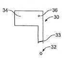
펌핑 챔버 내의 압력 진동의 주파수가 비교적 높다면, 버블은 또다른 팽창 사이클에 따르기 전에 압축 행정 중에 재-용해할 시간이 없다. 도 2는 버블 반경 사이클이 다수의 펌프 사이클 너머로 반경이 일반적으로 증가하는 것을 도시한다. 도 3a 내지 도 3c는 펌핑 챔버 내의 증가하는 버블 반경의 효과를 도시한다. 도 2 내지 도 3c를 보면, 시간 G에서, 프린트 요소(30)는 펌핑 챔버(34)의 압축 행정 중에 액적(32)을 소성 처리한다. 펌핑 챔버(34) 내에서, 메니스커스(meniscus; 33)와 함께 버블(36)은 반경이 R36이다. 그 다음에, 시간 H에서, 압축 행정 중에 버블(38; 도시되지 않음)은 다음 팽창 행정 중에 훨씬 더 성장하는 반경 R38을 가진다. 그 다음에 I 지점에서 팽창 행정 중에, 버블(40)은 프린트 챔버(34) 내에서 메니스커스(42)와 함께 크기 면에서 성장한다. 이러한 공정은 이전과 같이 반경 R44의 버블(44; 도시되지 않음), 반경 R46의 버블(46; 도시되지 않음)을 계속하여 생산한다. 최종적으로, 상당한 체적의 버블(48)이 펌핑 챔버 내에서 만들어진다. 이 지점에서, 액적 체적과 속도는 감소할 수 있고, 또는 극단적인 경우에 분사하는 액적 안으로 갔을 에너지가 그 대신에 버블을 압축하기 때문에 분사는 완전히 방지될 수 있다.If the frequency of pressure oscillation in the pumping chamber is relatively high, the bubble does not have time to re-dissolve during the compression stroke before following another expansion cycle. 2 shows that the bubble radius cycle generally increases in radius over multiple pump cycles. 3A-3C show the effect of increasing bubble radius in the pumping chamber. 2-3C, at time G,
보다 높은 선속도를 허용함으로써 처리량(throughput)을 증가시키기 때문에, 보다 높은 주파수에서 분사가 바람직할 수 있다. 작동 주파수에 대한 주요한 제한은 펌핑 챔버 내의 압력파를 위하여 왕복 운동에 소요되는 시간(round trip time) 에 의하여 결정되는 잉크젯의 공진 주파수이다. 그러므로, 펌핑 챔버를 보다 작게 만드는 것은 잉크젯의 고유 주파수를 증가시키고, 보다 높은 작동 주파수를 허용하게 된다. 노즐 직경을 보다 작게 제작하는 것도 역시 보다 높은 주파수에서 작동하는 데 도움을 주지만, 이것은 또한 보다 작은 액적 체적을 필요로 한다. 또한, 압력이 인가되는 시간을 감소시킴으로써 보다 높은 주파수에서 분사하는 것이 가능하지만, 이 경우 보다 높은 압력이 필요하다. 통상적으로, 음 압력(acoustic pressure)의 범위는 팽창 행정 상에서 주위보다 약 2 atm 낮은 압력에서, 그 이후 압축 행정 중에 주위보다 약 2-3 atm 높은 압력에 이른다. 정류 확산은 보다 높은 분사 주파수에서 보다 많은 문제를 야기하게 될 수 있다.Injection at higher frequencies may be desirable because it increases throughput by allowing higher linear velocities. The main limitation on the operating frequency is the resonant frequency of the inkjet, which is determined by the round trip time for the pressure wave in the pumping chamber. Therefore, making the pumping chamber smaller increases the natural frequency of the inkjet and allows higher operating frequencies. Smaller nozzle diameters also help to operate at higher frequencies, but this also requires smaller droplet volumes. It is also possible to spray at higher frequencies by reducing the time the pressure is applied, but in this case higher pressures are required. Typically, the range of acoustic pressures ranges from about 2 atm lower than ambient on the expansion stroke and then about 2-3 atm higher than ambient during the compression stroke. Commutation diffusion can cause more problems at higher injection frequencies.
일반적으로, 본 발명의 한 측면의 특징은 액적을 기판 상에 증착하는 장치이다. 이 장치는 기판을 위한 지지체, 펌핑 챔버를 포함하는 액적 배출 조립체(droplet ejection assembly), 제어기, 및 펌핑 챔버 내에 정류 확산형 버블 성장을 피하기 위하여 펌핑 챔버 내의 전체 압력을 임계 압력 수준 위로 증가시키는 정압(static pressure)의 공급원(source)을 포함한다. 액적 배출 조립체는 기판 상에 액적을 증착하는 지지체 위에 배치되며, 상기 펌핑 챔버 외에 변위 부재(displacement member) 및 액적을 배출하는 오리피스를 포함한다. 제어기는 액적을 배출하기 위하여 상기 변위 부재에 신호를 제공한다.In general, one aspect of the invention is an apparatus for depositing droplets on a substrate. The apparatus includes a support for a substrate, a droplet ejection assembly including a pumping chamber, a controller, and a positive pressure that increases the total pressure in the pumping chamber above the critical pressure level to avoid rectified diffused bubble growth within the pumping chamber. a source of static pressure. The droplet ejection assembly is disposed on a support for depositing droplets on a substrate and includes a displacement member and an orifice for ejecting droplets in addition to the pumping chamber. The controller provides a signal to the displacement member for ejecting the droplets.
몇몇 실시예에서, 정압은 절대 압력으로 약 1.5 대기압보다 더 크다.In some embodiments, the static pressure is greater than about 1.5 atmospheres in absolute pressure.
몇몇 실시예에서, 상기 신호는 약 8000 Hz보다 큰 주파수로 제공된다. 다른 실시예에서, 상기 신호는 약 8000 Hz보다 더 큰 주파수로 제공되며 정압은 절대 압력이 약 1.5 대기압보다 더 크다.In some embodiments, the signal is provided at a frequency greater than about 8000 Hz. In another embodiment, the signal is provided at a frequency greater than about 8000 Hz and the static pressure is greater than about 1.5 atmospheric pressure in absolute pressure.
배출된 액적은 잉크 또는 다른 적절한 액적-형성 재료일 수 있다. 기판은 종이 또는 임의의 다른 적절한 기판일 수 있다.The ejected droplets may be ink or other suitable droplet-forming material. The substrate may be paper or any other suitable substrate.
압력 공급원은 가압된 가스를 포함할 수 있다. 가스는 미립자(particulate matter)를 제거하기 위하여 여과될 수 있다. 습기 또는 기화된 용매가 가스에 더해질 수 있다. 가스는 공기 또는 임의의 다른 적절한 가스일 수 있다.The pressure source may comprise pressurized gas. The gas can be filtered to remove particulate matter. Moisture or vaporized solvent can be added to the gas. The gas may be air or any other suitable gas.
본 발명의 또다른 측면의 특징은 기판을 위한 지지체, 펌핑 챔버를 포함하는 액적 배출 조립체, 제어기, 인클로져 구조(enclosure structure), 및 펌핑 챔버 내에 정류 확산형 버블 성장을 피하기 위하여 펌핑 챔버 내의 전체 압력을 임계 압력 수준 위로 증가시키는 정압의 공급원을 포함하는 장치이다. 액적 배출 조립체는 지지체 상에 있는 기판 위에 액적을 증착하는 지지체 위에 배치된다. 액적 배출 조립체는 상기 펌핑 챔버 외에 변위 부재 및 액적을 배출하는 오리피스를 포함한다. 제어기는 액적을 배출하기 위하여 상기 변위 부재에 신호를 제공한다. 인클로져 구조는 지지체와 함께 포위된 영역을 형성되는데, 이를 통하여 액적은 기판 상으로 배출된다. 또한, 인클로져 구조는 지지체와 함께 기판이 이동하는 입구 간격 및 출구 간격도 형성한다. 입구 간격은 약 0.002 인치 내지 약 0.04 인치일 수 있다. 출구 간격은 약 0.002 인치 내지 약 0.04 인치일 수 있다.A further aspect of the invention features a support for a substrate, a droplet ejection assembly including a pumping chamber, a controller, an enclosure structure, and the total pressure in the pumping chamber to avoid rectified diffused bubble growth within the pumping chamber. A device comprising a source of constant pressure that increases above a critical pressure level. The droplet ejection assembly is disposed on a support that deposits droplets on a substrate on the support. The droplet ejection assembly includes a displacement member and an orifice for ejecting the droplet in addition to the pumping chamber. The controller provides a signal to the displacement member for ejecting the droplets. The enclosure structure forms an enclosed area with the support, through which droplets are ejected onto the substrate. The enclosure structure also forms an inlet gap and an outlet gap through which the substrate moves along with the support. The inlet spacing can be about 0.002 inches to about 0.04 inches. The outlet spacing can be about 0.002 inches to about 0.04 inches.
본 발명의 하나 이상의 실시예의 상세는 첨부 도면과 다음의 설명에서 제시된다. 본 발명의 다른 특징, 목적 및 장점들은 이 설명과 도면 그리고 청구범위로부터 명백할 것이다.The details of one or more embodiments of the invention are set forth in the accompanying drawings and the description below. Other features, objects, and advantages of the invention will be apparent from the description and drawings, and from the claims.
도 1은 주파수 진동이 낮은 경우에 잉크 압력 대 시간의 그래프이다.1 is a graph of ink pressure versus time when the frequency vibration is low.
도 2는 주파수 진동이 높은 경우에 잉크 압력 및 버블 반경 대 시간의 그래프이다.2 is a graph of ink pressure and bubble radius versus time when the frequency vibration is high.
도 3a 내지 도 3c는 이상화된 프린트헤드(printhead)에서 버블의 성장을 나타낸다.3A-3C show the growth of bubbles in the idealized printhead.
도 4는 기판 상에 인쇄하는 장치의 측면도이다.4 is a side view of an apparatus for printing on a substrate.
도 5는 도 4의 장치의 프린트 스테이션(print station)의 측면 개략도이다.FIG. 5 is a side schematic view of a print station of the apparatus of FIG. 4. FIG.
도 6은 선택적인 실시예의 측면도이다.6 is a side view of an alternative embodiment.
도 7은 상대 농도 대 인가된 음장(acoustic field)의 그래프이다.7 is a graph of relative concentration versus applied acoustic field.
다양한 도면에서 유사한 참조 부호는 유사한 요소를 가리킨다.Like reference symbols in the various drawings indicate like elements.
도 4는 기판(52; 예컨대, 종이) 상에 잉크 액적을 연속적으로 증착하는 장치(50)를 나타낸다. 기판(52)은 공급대(supply stand; 56) 상에 있는 롤(54)로부터 인출되어, 복수 개의 다양한 색깔의 액적을 기판(52) 상에 배치하는 일련의 액적- 증착 스테이션(droplet-depositing station; 58)으로 이송된다. 각 액적-증착 스테이션(58)은, 기판(52) 상에 액적을 증착하기 위하여 기판(52) 위에 배치되는 액적 배출 조립체(60)를 구비한다. 기판(52) 아래에 각 증착 스테이션(58)에는 기판 지지 구조(62)[예컨대, 비-다공성 압반(non-porous platen)]가 있다. 기판(52)이 최종 증착 스테이션(64)을 벗어난 후에, 그것은 예비-마무리 스테이션(pre-finishing station; 66)으로 갈 수 있다. 예비-마무리 스테이션(66)은 기판(52)을 건조시키는 데 사용될 수 있다. 그것은 UV 또는 기판(52)의 다른 방사선 경화(radiation curing)를 위하여 사용될 수 있다. 다음에, 기판(52)은 마무리 스테이션(68)으로 이동하는데, 여기서 그것은 접히고 슬리팅(slitting)되어 최종 산물(70)이 된다. 기판 이송 속도는 약 0.25-5.0 미터/초 이상이다. 액적 배출 조립체는 잉크 액적을 배출할 수 있다. 그것은 또한 방사선 경화 재료 또는 액적 형태로 운반 가능한 다른 재료도 배출할 수 있다.4 shows an
도 5는 실질적인 정류 확산을 피하도록 구성되는 높은 주파수의 액적 증착 스테이션(58)의 구성품을 보여준다. 이 장치에서, 펌핑 챔버 내의 잉크의 전체 압력은 상승되어, 팽창 행정 중에 달성되는 최소 전체 압력은 펌핑 챔버 내에 정류 확산형 버블 성장을 피할 수 있을 정도로 충분히 높다. 도 5에 개략적으로 나타난 바와 같이, 이것은 펌핑 챔버(92) 내에 그리고 액적 배출 영역(86) 내에 압력을 증가시킴으로써, 펌핑 챔버(92)와 잉크의 공급원(98)을 포함하는 프린트헤드를 인클로져(80) 내에서 포위함으로써, 그리고 슬릿(84)을 통하여 매니폴드(82)를 경유하여 공급되는 가압된 공기에 의하여 인클로져(80)를 상승된 압력 수준에 유지함으로써 달성된다. 매니폴드(82)는, 예컨대 퀵 커넥터(quick connector; 도시되지 않음)를 이용하여 압축기와 연결된다. 액적 배출 조립체(58)는 기판(52; 예컨대 종이) 위에 배치된다. 정압 공급원은 슬릿(84)을 이용하여 인클로져 구조(80) 내부에 매니폴드(82)를 경유하여 인가된다. 이런 방법으로 인가된 압력은 포위된 영역 (86) 내부와 그 주위에서의 난류(turbulence)를 감소시킨다. 주요 잉크 액적과 보다 작은 관련된 부수 액적은 난류 공기에 의하여 잘못 인도될 수 있기 때문에, 난류는 불량한 인쇄 품질을 야기할 수 있다. 기판(52)은 기판 지지 구조(62, 예컨대 비-다공성 압반)의 상단부 상에서 입구 간격(88)과 출구 간격(90)을 통과한다. 상기 압반은 고압 하의 기판(52)이 압반을 지나서 인입됨에 따라 너무 많은 드랙(drag)을 생성할 수 있기 때문에, 상기 압반은 비-다공성인 것이 바람직하다. 입구 간격(88) 및 출구 간격(90)은 기판(52) 위에서 측정할 때 약 0.002 인치 내지 약 0.04 인치이다. 이 간격이 너무 커지면 동력 요건이 제한될 수 있고, 이 간격이 너무 작아지면 이미지에 얼룩이 생기거나 페이퍼 잼(paper jam)이 발생할 수 있다. 압력이 너무 낮으면 정류 확산이 잠재적으로 발생할 수 있고, 압력이 너무 높으면 인클로져 구조(80)를 위한 구조적 요건은 금지적인(prohibitive) 것이 될 수 있다. 정압은 절대 압력으로 약 1.5 atm 내지 약 10 atm 인 것(대기압보다 0.5-9 atm 큰 값)이 바람직하다. 액적 배출 조립체(58)는 연결된 잉크 경로(94)를 갖춘 펌핑 챔버(92)를 포함한다. 잉크 경로(94)는 잉크(100)를 유지하는 잉크 저장소(reservoir; 98)로 연결되는 잉크 입구(96)에 의하여 연결된다. 전체 잉크 저장소(98)는 정압 상태에서 유지된다. 이것은 잉크 저장소(98) 내에 작은 구멍(103)에 의하여 달성된다. 펌핑 챔버(92)에 대하여 잉크 저장소 높이 차이에 기인하는 펌핑 챔버(92) 내에서의 작은 차이(예컨대, 0.1-0.3 psi)는, 펌프(102; 예컨대 작은 원심형 블로워 타입의 펌프)를 이용하여 수정된다. 물 또는 다른 용매가 노즐 내의 건조화(drying)를 억제하기 위하여 가스에 추가될 수 있다. 가스는 공기이거나 가스는 잉크의 노화(aging)를 지연시키기 위하여 공기에 비하여 감소된 산소 함유량을 가질 수 있다. 공기에 비하여 산소 함유량을 증가시키는 것은 UV 경화 가능한 잉크의 경화를 지연시킬 수 있다. 게다가, 가스는 미립자와 과다한 습기를 제거하기 위하여, 예컨대 HEPA 필터로 여과될 수 있다.5 shows components of a high frequency
도 6은 도 5의 장치 내의 인클로져(80) 하부에 정지 상태의 곡면형 지지체(62)를 대체하는 회전 드럼(104)을 인쇄 기판(52) 아래에 채용하는 선택적 실시예를 나타낸다.FIG. 6 shows an alternative embodiment employing a
도 7은 상대 농도(Ci/CO) 대 인가된 음 압력의 그래프이고, 버블 성장을 방지하기 위하여 요구되는 공기의 상대 농도 대 100 kHz 압력 장에서 다양한 정압상태에서 다양한 평형 상태의 버블 반경을 위하여 인가된 음 압력을 나타낸다. Ci는 잉크 내부의 공기의 농도이고, CO는 그것이 포화될 때 잉크 내의 공기의 농도이다. 100이라는 양(Ci/CO)은 퍼센트 포화를 나타낸다. 잉크가 장시간 공기와 접촉된 상태로 남겨진다면, 비율 Ci/CO는 100% 포화될 것이다. 많은 잉크젯 시스템에서, 잉크는 버블 문제를 피하기 위하여 사용 전에 잉크에서 가스는 제거된다. 잉크에 가스를 제거하는 것은 상대 농도 수치를 낮추며, 이는 보다 높이 인가되는 음장에서 버블 성장 없이 작업할 수 있게 한다. 정압을 증가시키는 것도 역시 보다 높이 인가되는 음 압력에서 버블 성장 없이 작업할 수 있게 한다. 그래프에서, PO는 정압이다. X축은 음 압력 장의 크기를 나타낸다. 주어진 크기의 버블은 주어진 정압, 인가된 음 압력 장 및 잉크 내 공기의 상대 농도에서 성장 또는 수축할 것이다. 정압을 증가시키고 잉크 내 공기의 상대 농도를 감소시키며 진동하는 인가된 압력 장의 크기를 감소시키는 것은, 대상물을 버블이 수축하는 방향으로 이동시킨다. 예를 들면, Rn = 5 미크론 : PO = 1 atm의 곡선 라벨은 5 미크론의 평형 상태의 반경(즉, 인가된 음 압력이 없는 경우의 반경) 및 정압 1 atm의 버블을 나타낸다. 이 곡선은, (+/-)40,000 파스칼의 음장을 인가하면 상대 농도가 100%(Ci/CO=1)일지라도 버블은 성장하지 않을 것이라는 것을 나타낸다. 만약 우리가 이 버블이 (+/-) 100,000 파스칼 압력 장에서 성장하지 않는 것을 바란다면, 우리는 상대 농도를 약 27%로 감소시킬 필요가 있다. 또다른 예에서, Rn = 0.2 미크론 : PO = 5 atm의 곡선 라벨은 0.2 미크론의 평형 상태의 반경(즉, 인가된 음파 압력이 없는 경우의 반경) 및 정압 5 atm의 버블을 위한 것이다. 곡선 위의 상태에 대하여 버블은 시간의 경과에 따라 성장할 것이고, 곡선 아래의 상태에 대하여 버블은 수축할 것이다. 도 7에 도시된 모든 상태 중에서, Rn = 0.2 미크론 : PO = 5 atm은 정류 확산에 기인하는 버블 성장에 가장 낮은 경향을 가질 것이다. 이 경우에, 공기로 포화되는 잉크 내의 버블(Ci/CO = 1)은 인가된 음장이 450000 파스칼을 초과할 때까지 성장하지 않을 것이다. 잉크를 상대 농도 0.2로 기포를 제거함으로써, 580000 파스칼을 넘는 음 압력 장은 버블 성장 없이 인가될 수 있다. 도 7은 상대 농도 Ci/CO를 감소시키는 것은 제한된 효과를 가진다는 것을 보여준다. 예컨대, Rn = 1 내지 Rn = 5의 응집 장소 크기에 대하여, 분사(jet) 내에 인가될 수 있는 최대 음장은 약 150,000 파스칼이고, Ci/CO가 1%로 감소될지라도 이는 어렵다. 대조적으로, 정압을 증가시킴으로써, 우리는 버블 성장을 야기함이 없이 네 배 더 높은 음장을 인가할 수 있다. 헨리의 법칙에 의하면, 액체 내의 가스의 용해도는 액체와 접촉하는 가스의 압력에 직접 비례한다. 그러므로, 잉크 위의 공기 압력이 1 atm에서 5 atm으로 상승할 때, 상대 농도는 인자 5에 의하여 감소된다. 1 atm에서 100%로 포화 상태인 잉크가 이제 5 atm인 저장소 안으로 펌핑되면, 그 경우 Ci/CO = 20%가 된다. 물론, 100% 포화 상태로 재-평형 없이 잉크가 펌핑 챔버 안으로 유입되도록 조치가 취해진다. 재-평형은 공기와 접촉 상태에 있는 분사하는 유체의 표면적을 최소화함으로써, 및/또는 재-평형을 방지할 정도로 충분히 빠른 비율로 유체를 분사함으로써 피할 수 있다.FIG. 7 is a graph of relative concentration (Ci / CO) vs. applied negative pressure and applied for various equilibrium bubble radii at various static pressures at 100 kHz pressure field versus the relative concentration of air required to prevent bubble growth. Indicates negative pressure. Ci is the concentration of air inside the ink and CO is the concentration of air in the ink when it is saturated. The amount 100 (Ci / CO) represents percent saturation. If the ink is left in contact with air for a long time, the ratio Ci / CO will be 100% saturated. In many inkjet systems, the ink is degassed from the ink before use to avoid bubble problems. Degassing the ink lowers the relative concentration value, which allows it to work without bubble growth in the higher applied sound field. Increasing the static pressure also allows working without bubble growth at higher applied negative pressures. In the graph, PO is static pressure. The x-axis represents the magnitude of the negative pressure field. Bubbles of a given size will grow or shrink at a given static pressure, applied negative pressure field and relative concentration of air in the ink. Increasing the static pressure, decreasing the relative concentration of air in the ink, and reducing the size of the oscillating applied pressure field move the object in the direction in which the bubble contracts. For example, a curved label of Rn = 5 microns: PO = 1 atm represents a 5 micron equilibrium radius (i.e. no radial pressure applied) and a static pressure bubble of 1 atm. This curve indicates that applying a sound field of (+/-) 40,000 Pascal will not grow bubbles even if the relative concentration is 100% (Ci / CO = 1). If we do not want this bubble to grow in a (+/-) 100,000 Pascal pressure field, we need to reduce the relative concentration to about 27%. In another example, a curved label of Rn = 0.2 micron: PO = 5 atm is for a bubble of equilibrium radius of 0.2 microns (i.e., radius without applied sonic pressure) and 5 atm static pressure. For states above the curve, the bubble will grow over time, and for states below the curve, the bubble will contract. Of all the states shown in FIG. 7, Rn = 0.2 micron: PO = 5 atm will have the lowest tendency to bubble growth due to commutation diffusion. In this case, bubbles in the ink saturated with air (Ci / CO = 1) will not grow until the applied sound field exceeds 450000 Pascals. By removing the bubbles in the ink at a relative concentration of 0.2, a negative pressure field above 580000 Pascals can be applied without bubble growth. 7 shows that reducing the relative concentration Ci / CO has a limited effect. For example, for flocculation site sizes of Rn = 1 to Rn = 5, the maximum sound field that can be applied in the jet is about 150,000 Pascals, even though Ci / CO is reduced to 1%. In contrast, by increasing the static pressure, we can apply a sound field four times higher without causing bubble growth. According to Henry's law, the solubility of a gas in a liquid is directly proportional to the pressure of the gas in contact with the liquid. Therefore, when the air pressure on the ink rises from 1 atm to 5 atm, the relative concentration is reduced by the factor 5. If an ink saturated at 100% at 1 atm is now pumped into a reservoir at 5 atm, then Ci / CO = 20%. Of course, measures are taken to allow ink to flow into the pumping chamber without re-equilibration to 100% saturation. Re-equilibrium can be avoided by minimizing the surface area of the spraying fluid in contact with air, and / or by spraying the fluid at a rate fast enough to prevent re-equilibrium.
본 발명의 많은 실시예가 설명되었다. 그럼에도 불구하고, 본 발명의 사상 및 범위를 벗어남이 없이 다양한 수정이 이루어질 수 있다는 것을 이해할 것이다. 예를 들면, 증착된 액적은 잉크 또는 다른 재료일 수 있다. 예를 들면, 증착된 액적은 UV 또는 다른 방사선 경화 가능한 재료 또는 액적으로 전송 가능한 재료일 수 있다. 예를 들면, 설명된 장치는 정밀 분배 시스템(precision dispensing system)의 일부일 수 있다. 따라서, 다른 실시예도 다음의 청구범위 내에 있다.Many embodiments of the invention have been described. Nevertheless, it will be understood that various modifications may be made without departing from the spirit and scope of the invention. For example, the deposited droplets may be ink or other material. For example, the deposited droplets may be UV or other radiation curable materials or materials transferable to the droplets. For example, the described apparatus can be part of a precision dispensing system. Accordingly, other embodiments are within the scope of the following claims.
Claims (30)
Translated fromKoreanApplications Claiming Priority (3)
| Application Number | Priority Date | Filing Date | Title |
|---|---|---|---|
| US10/462,092 | 2003-06-13 | ||
| US10/462,092US6923866B2 (en) | 2003-06-13 | 2003-06-13 | Apparatus for depositing droplets |
| PCT/US2004/018810WO2004113078A2 (en) | 2003-06-13 | 2004-06-14 | Apparatus for depositing droplets |
Publications (2)
| Publication Number | Publication Date |
|---|---|
| KR20060027336A KR20060027336A (en) | 2006-03-27 |
| KR101154583B1true KR101154583B1 (en) | 2012-06-08 |
Family
ID=33511393
Family Applications (1)
| Application Number | Title | Priority Date | Filing Date |
|---|---|---|---|
| KR1020057023895AExpired - Fee RelatedKR101154583B1 (en) | 2003-06-13 | 2004-06-14 | Apparatus for depositing droplets |
Country Status (8)
| Country | Link |
|---|---|
| US (3) | US6923866B2 (en) |
| EP (1) | EP1633565B1 (en) |
| JP (1) | JP4447014B2 (en) |
| KR (1) | KR101154583B1 (en) |
| CN (1) | CN100420576C (en) |
| AT (1) | ATE487603T1 (en) |
| DE (1) | DE602004030006D1 (en) |
| WO (1) | WO2004113078A2 (en) |
Families Citing this family (6)
| Publication number | Priority date | Publication date | Assignee | Title |
|---|---|---|---|---|
| US6923866B2 (en)* | 2003-06-13 | 2005-08-02 | Spectra, Inc. | Apparatus for depositing droplets |
| JP3791518B2 (en)* | 2003-10-29 | 2006-06-28 | セイコーエプソン株式会社 | Film forming method and film forming apparatus |
| JP5008307B2 (en)* | 2005-02-03 | 2012-08-22 | オセ−テクノロジーズ・ベー・ヴエー | Inkjet printer printing method and inkjet printer modified to apply the method |
| US20100102471A1 (en)* | 2008-10-24 | 2010-04-29 | Molecular Imprints, Inc. | Fluid transport and dispensing |
| DE102009013477B4 (en)* | 2009-03-19 | 2012-01-12 | Khs Gmbh | Printing device for printing on bottles or similar containers |
| US8640717B2 (en) | 2010-04-12 | 2014-02-04 | Thomas Robert McCarthy | Multipurpose sequential droplet applicator |
Family Cites Families (32)
| Publication number | Priority date | Publication date | Assignee | Title |
|---|---|---|---|---|
| US4106032A (en)* | 1974-09-26 | 1978-08-08 | Matsushita Electric Industrial Co., Limited | Apparatus for applying liquid droplets to a surface by using a high speed laminar air flow to accelerate the same |
| JPS54123950A (en)* | 1978-03-17 | 1979-09-26 | Matsushita Electric Ind Co Ltd | Ink jet recorder |
| JPS58220758A (en) | 1982-06-16 | 1983-12-22 | Matsushita Electric Ind Co Ltd | Inkjet recording device |
| US4558326A (en)* | 1982-09-07 | 1985-12-10 | Konishiroku Photo Industry Co., Ltd. | Purging system for ink jet recording apparatus |
| US4599626A (en)* | 1984-08-02 | 1986-07-08 | Metromedia, Inc. | Ink drop ejecting head |
| US4613875A (en)* | 1985-04-08 | 1986-09-23 | Tektronix, Inc. | Air assisted ink jet head with projecting internal ink drop-forming orifice outlet |
| US4591873A (en)* | 1985-04-12 | 1986-05-27 | Eastman Kodak Company | Ink jet printing apparatus with orifice array cleaning system |
| US4651161A (en) | 1986-01-17 | 1987-03-17 | Metromedia, Inc. | Dynamically varying the pressure of fluid to an ink jet printer head |
| JPS62292438A (en)* | 1986-06-13 | 1987-12-19 | Canon Inc | Inkjet recording device |
| US4788556A (en)* | 1987-04-28 | 1988-11-29 | Spectra, Inc. | Deaeration of ink in an ink jet system |
| US4947184A (en)* | 1988-02-22 | 1990-08-07 | Spectra, Inc. | Elimination of nucleation sites in pressure chamber for ink jet systems |
| US4825227A (en)* | 1988-02-29 | 1989-04-25 | Spectra, Inc. | Shear mode transducer for ink jet systems |
| US5065169A (en)* | 1988-03-21 | 1991-11-12 | Hewlett-Packard Company | Device to assure paper flatness and pen-to-paper spacing during printing |
| US4940995A (en)* | 1988-11-18 | 1990-07-10 | Spectra, Inc. | Removal of dissolved gas from ink in an ink jet system |
| US4995940A (en)* | 1988-11-18 | 1991-02-26 | Spectra, Inc. | Method for forming a gas removing device for an ink jet system |
| US4937598A (en)* | 1989-03-06 | 1990-06-26 | Spectra, Inc. | Ink supply system for an ink jet head |
| US5406318A (en)* | 1989-11-01 | 1995-04-11 | Tektronix, Inc. | Ink jet print head with electropolished diaphragm |
| JPH03234539A (en) | 1990-02-09 | 1991-10-18 | Canon Inc | inkjet recording device |
| US5155498A (en)* | 1990-07-16 | 1992-10-13 | Tektronix, Inc. | Method of operating an ink jet to reduce print quality degradation resulting from rectified diffusion |
| US5265315A (en)* | 1990-11-20 | 1993-11-30 | Spectra, Inc. | Method of making a thin-film transducer ink jet head |
| US5519420A (en) | 1992-12-21 | 1996-05-21 | Ncr Corporation | Air system to protect ink jet head |
| US5474032A (en)* | 1995-03-20 | 1995-12-12 | Krietzman; Mark H. | Suspended feline toy and exerciser |
| US5742313A (en)* | 1994-10-31 | 1998-04-21 | Spectra, Inc. | Efficient ink jet head arrangement |
| US5880759A (en) | 1995-04-12 | 1999-03-09 | Eastman Kodak Company | Liquid ink printing apparatus and system |
| US5739254A (en)* | 1996-08-29 | 1998-04-14 | Xerox Corporation | Process for haloalkylation of high performance polymers |
| JPH10138461A (en) | 1996-11-06 | 1998-05-26 | Hitachi Ltd | Printing device |
| US6281912B1 (en)* | 2000-05-23 | 2001-08-28 | Silverbrook Research Pty Ltd | Air supply arrangement for a printer |
| EP1289764B1 (en) | 2000-05-24 | 2007-07-25 | Silverbrook Research Pty. Limited | Air supply arrangement for a printer |
| JP2002086725A (en)* | 2000-07-11 | 2002-03-26 | Matsushita Electric Ind Co Ltd | Ink jet head, method for manufacturing the same, and ink jet recording apparatus |
| WO2002088265A1 (en)* | 2001-04-27 | 2002-11-07 | Ajinomoto Co., Inc. | Decoloring ink for ink jet pringing and ink jet printing method using it |
| US6588889B2 (en)* | 2001-07-16 | 2003-07-08 | Eastman Kodak Company | Continuous ink-jet printing apparatus with pre-conditioned air flow |
| US6923866B2 (en)* | 2003-06-13 | 2005-08-02 | Spectra, Inc. | Apparatus for depositing droplets |
- 2003
- 2003-06-13USUS10/462,092patent/US6923866B2/ennot_activeExpired - Lifetime
- 2004
- 2004-06-14CNCNB2004800186128Apatent/CN100420576C/ennot_activeExpired - Lifetime
- 2004-06-14JPJP2006533774Apatent/JP4447014B2/ennot_activeExpired - Lifetime
- 2004-06-14KRKR1020057023895Apatent/KR101154583B1/ennot_activeExpired - Fee Related
- 2004-06-14WOPCT/US2004/018810patent/WO2004113078A2/enactiveApplication Filing
- 2004-06-14DEDE602004030006Tpatent/DE602004030006D1/ennot_activeExpired - Lifetime
- 2004-06-14ATAT04755154Tpatent/ATE487603T1/ennot_activeIP Right Cessation
- 2004-06-14EPEP04755154Apatent/EP1633565B1/ennot_activeExpired - Lifetime
- 2005
- 2005-05-16USUS11/130,533patent/US7326439B2/ennot_activeExpired - Lifetime
- 2007
- 2007-12-21USUS11/963,054patent/US20080094433A1/ennot_activeAbandoned
Also Published As
| Publication number | Publication date |
|---|---|
| CN100420576C (en) | 2008-09-24 |
| ATE487603T1 (en) | 2010-11-15 |
| JP4447014B2 (en) | 2010-04-07 |
| KR20060027336A (en) | 2006-03-27 |
| US7326439B2 (en) | 2008-02-05 |
| US20050206689A1 (en) | 2005-09-22 |
| WO2004113078A3 (en) | 2005-07-07 |
| US20080094433A1 (en) | 2008-04-24 |
| JP2007500636A (en) | 2007-01-18 |
| US6923866B2 (en) | 2005-08-02 |
| EP1633565A4 (en) | 2009-08-05 |
| EP1633565A2 (en) | 2006-03-15 |
| WO2004113078A2 (en) | 2004-12-29 |
| CN1816451A (en) | 2006-08-09 |
| DE602004030006D1 (en) | 2010-12-23 |
| HK1091441A1 (en) | 2007-01-19 |
| US20040250758A1 (en) | 2004-12-16 |
| EP1633565B1 (en) | 2010-11-10 |
Similar Documents
| Publication | Publication Date | Title |
|---|---|---|
| JP4885879B2 (en) | Fluid drop discharge | |
| US20080094433A1 (en) | Apparatus for Depositing Droplets | |
| US20090073215A1 (en) | Printheads and systems using printheads | |
| JP2002522279A (en) | Inkjet printer that prints directly on media | |
| CN100581823C (en) | Drop ejection system and method | |
| US20050195248A1 (en) | Discharge determination device and method | |
| EP1673227B1 (en) | Apparatus for depositing droplets | |
| KR101323209B1 (en) | Printheads and systems using printheads | |
| HK1091441B (en) | Apparatus for depositing droplets | |
| JPH10230598A (en) | Liquid droplet ejection apparatus | |
| JP2927265B2 (en) | Droplet ejector | |
| EP1110733A1 (en) | Ink jet printer including a printhead and a method of removing bubbles from ink jet printheads | |
| KR20070080118A (en) | Bubble removing device and method of inkjet printing system | |
| JP2008260288A (en) | Method, device, and printhead for continuous mems ink-jet | |
| HK1091785B (en) | Apparatus for depositing droplets |
Legal Events
| Date | Code | Title | Description |
|---|---|---|---|
| PA0105 | International application | St.27 status event code:A-0-1-A10-A15-nap-PA0105 | |
| PG1501 | Laying open of application | St.27 status event code:A-1-1-Q10-Q12-nap-PG1501 | |
| PN2301 | Change of applicant | St.27 status event code:A-3-3-R10-R13-asn-PN2301 St.27 status event code:A-3-3-R10-R11-asn-PN2301 | |
| A201 | Request for examination | ||
| P11-X000 | Amendment of application requested | St.27 status event code:A-2-2-P10-P11-nap-X000 | |
| P13-X000 | Application amended | St.27 status event code:A-2-2-P10-P13-nap-X000 | |
| PA0201 | Request for examination | St.27 status event code:A-1-2-D10-D11-exm-PA0201 | |
| E902 | Notification of reason for refusal | ||
| PE0902 | Notice of grounds for rejection | St.27 status event code:A-1-2-D10-D21-exm-PE0902 | |
| T11-X000 | Administrative time limit extension requested | St.27 status event code:U-3-3-T10-T11-oth-X000 | |
| T11-X000 | Administrative time limit extension requested | St.27 status event code:U-3-3-T10-T11-oth-X000 | |
| T11-X000 | Administrative time limit extension requested | St.27 status event code:U-3-3-T10-T11-oth-X000 | |
| P11-X000 | Amendment of application requested | St.27 status event code:A-2-2-P10-P11-nap-X000 | |
| P13-X000 | Application amended | St.27 status event code:A-2-2-P10-P13-nap-X000 | |
| E701 | Decision to grant or registration of patent right | ||
| PE0701 | Decision of registration | St.27 status event code:A-1-2-D10-D22-exm-PE0701 | |
| GRNT | Written decision to grant | ||
| PR0701 | Registration of establishment | St.27 status event code:A-2-4-F10-F11-exm-PR0701 | |
| PR1002 | Payment of registration fee | St.27 status event code:A-2-2-U10-U12-oth-PR1002 Fee payment year number:1 | |
| PG1601 | Publication of registration | St.27 status event code:A-4-4-Q10-Q13-nap-PG1601 | |
| FPAY | Annual fee payment | Payment date:20150522 Year of fee payment:4 | |
| PR1001 | Payment of annual fee | St.27 status event code:A-4-4-U10-U11-oth-PR1001 Fee payment year number:4 | |
| FPAY | Annual fee payment | Payment date:20160517 Year of fee payment:5 | |
| PR1001 | Payment of annual fee | St.27 status event code:A-4-4-U10-U11-oth-PR1001 Fee payment year number:5 | |
| P22-X000 | Classification modified | St.27 status event code:A-4-4-P10-P22-nap-X000 | |
| FPAY | Annual fee payment | Payment date:20170522 Year of fee payment:6 | |
| PR1001 | Payment of annual fee | St.27 status event code:A-4-4-U10-U11-oth-PR1001 Fee payment year number:6 | |
| FPAY | Annual fee payment | Payment date:20180517 Year of fee payment:7 | |
| PR1001 | Payment of annual fee | St.27 status event code:A-4-4-U10-U11-oth-PR1001 Fee payment year number:7 | |
| FPAY | Annual fee payment | Payment date:20190515 Year of fee payment:8 | |
| PR1001 | Payment of annual fee | St.27 status event code:A-4-4-U10-U11-oth-PR1001 Fee payment year number:8 | |
| PR1001 | Payment of annual fee | St.27 status event code:A-4-4-U10-U11-oth-PR1001 Fee payment year number:9 | |
| PR1001 | Payment of annual fee | St.27 status event code:A-4-4-U10-U11-oth-PR1001 Fee payment year number:10 | |
| PR1001 | Payment of annual fee | St.27 status event code:A-4-4-U10-U11-oth-PR1001 Fee payment year number:11 | |
| PR1001 | Payment of annual fee | St.27 status event code:A-4-4-U10-U11-oth-PR1001 Fee payment year number:12 | |
| PC1903 | Unpaid annual fee | St.27 status event code:A-4-4-U10-U13-oth-PC1903 Not in force date:20240602 Payment event data comment text:Termination Category : DEFAULT_OF_REGISTRATION_FEE | |
| PC1903 | Unpaid annual fee | St.27 status event code:N-4-6-H10-H13-oth-PC1903 Ip right cessation event data comment text:Termination Category : DEFAULT_OF_REGISTRATION_FEE Not in force date:20240602 |