KR101150491B1 - Metallic Pattern - Google Patents
Metallic PatternDownload PDFInfo
- Publication number
- KR101150491B1 KR101150491B1KR1020090128009AKR20090128009AKR101150491B1KR 101150491 B1KR101150491 B1KR 101150491B1KR 1020090128009 AKR1020090128009 AKR 1020090128009AKR 20090128009 AKR20090128009 AKR 20090128009AKR 101150491 B1KR101150491 B1KR 101150491B1
- Authority
- KR
- South Korea
- Prior art keywords
- nozzle
- plate
- resin
- mold
- interposed
- Prior art date
- Legal status (The legal status is an assumption and is not a legal conclusion. Google has not performed a legal analysis and makes no representation as to the accuracy of the status listed.)
- Expired - Fee Related
Links
Images

Classifications
- B—PERFORMING OPERATIONS; TRANSPORTING
- B29—WORKING OF PLASTICS; WORKING OF SUBSTANCES IN A PLASTIC STATE IN GENERAL
- B29C—SHAPING OR JOINING OF PLASTICS; SHAPING OF MATERIAL IN A PLASTIC STATE, NOT OTHERWISE PROVIDED FOR; AFTER-TREATMENT OF THE SHAPED PRODUCTS, e.g. REPAIRING
- B29C45/00—Injection moulding, i.e. forcing the required volume of moulding material through a nozzle into a closed mould; Apparatus therefor
- B29C45/17—Component parts, details or accessories; Auxiliary operations
- B29C45/26—Moulds
- B29C45/2602—Mould construction elements
- B—PERFORMING OPERATIONS; TRANSPORTING
- B29—WORKING OF PLASTICS; WORKING OF SUBSTANCES IN A PLASTIC STATE IN GENERAL
- B29C—SHAPING OR JOINING OF PLASTICS; SHAPING OF MATERIAL IN A PLASTIC STATE, NOT OTHERWISE PROVIDED FOR; AFTER-TREATMENT OF THE SHAPED PRODUCTS, e.g. REPAIRING
- B29C45/00—Injection moulding, i.e. forcing the required volume of moulding material through a nozzle into a closed mould; Apparatus therefor
- B29C45/17—Component parts, details or accessories; Auxiliary operations
- B29C45/20—Injection nozzles
- B—PERFORMING OPERATIONS; TRANSPORTING
- B29—WORKING OF PLASTICS; WORKING OF SUBSTANCES IN A PLASTIC STATE IN GENERAL
- B29C—SHAPING OR JOINING OF PLASTICS; SHAPING OF MATERIAL IN A PLASTIC STATE, NOT OTHERWISE PROVIDED FOR; AFTER-TREATMENT OF THE SHAPED PRODUCTS, e.g. REPAIRING
- B29C33/00—Moulds or cores; Details thereof or accessories therefor
- B29C33/02—Moulds or cores; Details thereof or accessories therefor with incorporated heating or cooling means
- B29C2033/023—Thermal insulation of moulds or mould parts
- B—PERFORMING OPERATIONS; TRANSPORTING
- B29—WORKING OF PLASTICS; WORKING OF SUBSTANCES IN A PLASTIC STATE IN GENERAL
- B29C—SHAPING OR JOINING OF PLASTICS; SHAPING OF MATERIAL IN A PLASTIC STATE, NOT OTHERWISE PROVIDED FOR; AFTER-TREATMENT OF THE SHAPED PRODUCTS, e.g. REPAIRING
- B29C45/00—Injection moulding, i.e. forcing the required volume of moulding material through a nozzle into a closed mould; Apparatus therefor
- B29C45/17—Component parts, details or accessories; Auxiliary operations
- B29C45/26—Moulds
- B29C45/27—Sprue channels ; Runner channels or runner nozzles
- B29C45/2737—Heating or cooling means therefor
- B29C2045/2753—Heating means and cooling means, e.g. heating the runner nozzle and cooling the nozzle tip
- B—PERFORMING OPERATIONS; TRANSPORTING
- B29—WORKING OF PLASTICS; WORKING OF SUBSTANCES IN A PLASTIC STATE IN GENERAL
- B29C—SHAPING OR JOINING OF PLASTICS; SHAPING OF MATERIAL IN A PLASTIC STATE, NOT OTHERWISE PROVIDED FOR; AFTER-TREATMENT OF THE SHAPED PRODUCTS, e.g. REPAIRING
- B29C45/00—Injection moulding, i.e. forcing the required volume of moulding material through a nozzle into a closed mould; Apparatus therefor
- B29C45/17—Component parts, details or accessories; Auxiliary operations
- B29C45/26—Moulds
- B29C45/27—Sprue channels ; Runner channels or runner nozzles
- B29C2045/2766—Heat insulation between nozzle and mould
Landscapes
- Engineering & Computer Science (AREA)
- Manufacturing & Machinery (AREA)
- Mechanical Engineering (AREA)
- Moulds For Moulding Plastics Or The Like (AREA)
Abstract
Translated fromKoreanDescription
Translated fromKorean본 발명은 금형에 관한 것이다.The present invention relates to a mold.
금형은 그 내부에 일정한 형상을 가지는 캐비티가 형성되며, 이 캐비티에 용융된 수지를 충전하고, 이를 경화시켜 성형품을 형성할 수 있는 장치를 말한다.The mold is a device in which a cavity having a predetermined shape is formed therein, and filled with the molten resin in the cavity, and cured to form a molded article.
이 때, 금형에는 캐비티에 수지를 토출하기 위해 노즐부가 설치될 수 있다. 노즐부는 수지의 양을 절감하고 성형품의 품질을 향상시키기 위해 수지를 가열하는 가열부를 구비할 수 있으며, 이로 인해, 캐비티의 노즐과 인접한 측에는 국부적인 온도 상승이 발생하게 된다.At this time, the mold may be provided with a nozzle portion for discharging the resin in the cavity. The nozzle portion may have a heating portion for heating the resin to reduce the amount of resin and improve the quality of the molded article, whereby a local temperature rise occurs on the side adjacent to the nozzle of the cavity.
금형의 국부적인 온도 상승은, 금형의 나머지 부분과 온도 차를 야기시켜 금형에 열 응력이 발생되는 문제가 있었다.The local temperature rise of the mold causes a temperature difference with the rest of the mold, causing a thermal stress to be generated in the mold.
본 발명은 열 전달 방지구조를 구비하는 금형을 제공하는 것이다.The present invention is to provide a mold having a heat transfer prevention structure.
본 발명의 일 측면에 따르면, 수지를 토출하는 노즐부; 노즐부를 지지하는 노즐플레이트; 수지가 충전되는 성형캐비티가 형성되는 성형플레이트; 수지가 충전되어 성형캐비티가 단열되도록 노즐부와 성형캐비티 사이에 개재되는 더미캐비티를 포함하는 금형이 제공된다.According to an aspect of the invention, the nozzle unit for discharging the resin; A nozzle plate supporting the nozzle unit; A molding plate on which a molding cavity filled with resin is formed; There is provided a mold including a dummy cavity interposed between the nozzle portion and the molding cavity so that the resin is filled to insulate the molding cavity.
여기서, 금형은 노즐플레이트와 성형플레이트 사이에 개재되며, 노즐부와 성형캐비티를 연결하는 연결유로가 형성되는 연결플레이트를 더 포함할 수 있다.Here, the mold may further include a connection plate interposed between the nozzle plate and the molding plate, and a connection flow path for connecting the nozzle unit and the molding cavity is formed.
이 때, 더미캐비티는 노즐부와 연결유로 사이에 개재되도록 연결플레이트에 형성될 수 있다.At this time, the dummy cavity may be formed in the connection plate so as to be interposed between the nozzle portion and the connection passage.
그리고, 노즐부는 수지가 공급되는 공급유로가 형성되는 노즐; 공급유로로 공급되는 수지를 가열하는 가열부; 및 노즐이 삽입되는 부쉬를 포함할 수 있다.The nozzle unit may include a nozzle in which a supply passage through which the resin is supplied is formed; A heating unit for heating the resin supplied to the supply passage; And a bush into which the nozzle is inserted.
여기서, 금형은 노즐과 부쉬 사이에 개재되는 제1 에어 갭을 더 포함할 수 있다.Here, the mold may further include a first air gap interposed between the nozzle and the bush.
그리고, 금형은 노즐부를 지지하도록, 노즐부와 노즐플레이트 사이에 개재되는 지지부를 더 포함할 수 있으며, 지지부와 부쉬 사이에 개재되는 제2 에어 갭을 더 포함할 수 있다.The mold may further include a support part interposed between the nozzle part and the nozzle plate to support the nozzle part, and may further include a second air gap interposed between the support part and the bush.
그리고, 금형은 지지부와 노즐플레이트 사이에 개재되는 제3 에어 갭을 더 포함할 수 있다.In addition, the mold may further include a third air gap interposed between the support and the nozzle plate.
본 발명의 실시예에 따르면, 노즐의 열이 그와 인접한 금형의 나머지 부분으로 절단되는 것을 방지할 수 있다.According to an embodiment of the present invention, it is possible to prevent the rows of nozzles from being cut into the rest of the mold adjacent thereto.
본 발명의 특징, 이점이 이하의 도면과 발명의 상세한 설명으로부터 명확해질 것이다.The features and advantages of the present invention will become apparent from the following drawings and detailed description of the invention.
이하, 본 발명에 따른 금형의 실시예를 첨부도면을 참조하여 상세히 설명하기로 하며, 첨부 도면을 참조하여 설명함에 있어, 동일하거나 대응하는 구성 요소는 동일한 도면번호를 부여하고 이에 대한 중복되는 설명은 생략하기로 한다.Hereinafter, an embodiment of a mold according to the present invention will be described in detail with reference to the accompanying drawings, in the description with reference to the accompanying drawings, the same or corresponding components are given the same reference numerals and duplicate description thereof It will be omitted.
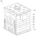
도 1은 본 발명의 일 실시예에 따른 금형(1000)을 나타낸 사시도이고, 도 2는 본 발명의 일 실시예에 따른 금형(1000)의 일부를 나타낸 단면도이다. 도 1 내지 도 2에 도시된 바와 같이, 본 발명의 일 실시예에 따른 금형(1000)은 노즐부(100), 노즐(130)플레이트(210), 연결플레이트(220), 성형플레이트(230), 지지부(150), 더미캐비티(224), 제1 에어 갭(310), 제2 에어 갭(320) 및 제3 에어 갭(330)을 포함함으로써, 노즐(130)로부터 인접한 플레이트 측으로 열이 전달되는 것을 방지할 수 있다.1 is a perspective view showing a
금형(1000)은 노즐(130)플레이트(210), 연결플레이트(220), 성형플레이트(230) 및 복수의 보조플레이트(202, 204, 206, 208, 212, 214)가 적층되는 형태를 가질 수 있다.The
노즐(130)플레이트(210)는 그 내부에 노즐부(100)를 지지하는 홈이 형성될 수 있다.Nozzle 130 The
노즐부(100)는 노즐(130), 가열부(120), 부쉬(140)를 포함할 수 있다.The
노즐(130)은 그 내부에 수지가 공급되는 공급유로(110)가 형성될 수 있다. 공급유로(110)의 둘레에는 공급유로(110) 내부로 유동되는 수지를 가열하기 위한 가열부(120)가 형성될 수 있다.The
가열부(120)는 전기를 공급받으면 열을 발생시키는 열선을 포함할 수 있다. 가열부(120)를 구비하는 공급유로(110)를 핫러너(hot runner)라 할 수 있다.The
노즐(130)은 부쉬(140)에 삽입될 수 있다. 부쉬(140)는 노즐(130)을 감싸는 구조를 가지며, 노즐부(100)의 외관을 이룰 수 있다. 이 때, 노즐(130)과 부쉬(140) 사이에는 공기가 충전되는 홈, 즉 제1 에어 갭(310)(air gap)이 개재될 수 있다.The
제1 에어 갭(310)은 노즐(130)의 열이, 노즐(130)과 인접한 노즐(130)플레이트(210), 연결플레이트(220) 및 성형플레이트(230)로 전달되는 것을 방지할 수 있다.The
부쉬(140)는 지지부(150)에 의해 지지될 수 있다. 지지부(150)는 노즐부(100)의 형상에 대응하여 길이 방향으로 연장되는 형태를 가지며, 그 내부에 중공부가 형성되며, 이 중공부에 노즐부(100)가 삽입될 수 있다.The
부쉬(140)이 말단은 하단으로 갈수록 단면적이 감소하는 원추형상으로 이루어질 수 있으며, 이 원추형상의 부쉬(140) 말단의 경사진 부분과 지지부(150) 사이 에 공기가 충전되는 홈, 즉 제2 에어 갭(320)이 형성될 수 있다. 제2 에어 갭(320)은 노즐(130)의 열이, 노즐(130)과 인접한 노즐(130)플레이트(210), 연결플레이트(220) 및 성형플레이트(230)로 전달되는 것을 방지할 수 있다.The end of the
지지부(150)는, 지지부(150)가 삽입될 수 있는 홈이 형성되는 노즐(130)플레이트(210)에 의해 지지될 수 있다. 노즐(130)플레이트(210)는 그 내부에 지지부(150)를 수용하며, 지지부(150)의 양측을 지지할 수 있다.The
이 때, 지지부(150)와 노즐(130)플레이트(210) 사이에는 공기가 충전되는 홈, 즉 제3 에어 갭(330)이 형성될 수 있다. 제3 에어 갭(330)은 노즐(130)의 열이, 노즐(130)과 인접한 노즐(130)플레이트(210), 연결플레이트(220) 및 성형플레이트(230)로 전달되는 것을 방지할 수 있다.At this time, a groove filled with air, that is, a
성형플레이트(230)의 하단에는 연결플레이트(220)가 결합될 수 있다. 연결플레이트(220)의 내부에는, 공급유로(110)의 위치에 상응하여 연결플레이트(220)를 상하로 관통하는 연결유로(222)가 형성될 수 있다.The
연결유로(222)는 후술할 성형캐비티(232)와 공급유로(110) 사이에 개재되어, 공급유로(110)를 통해 토출된 수지가 성형캐비티(232)로 유입될 수 있는 통로를 제공할 수 있다. 이 때, 연결유로(222)와 같이 가열장치를 구비하지 않는 유로를 콜드러너(cold runner)라 할 수 있다.The
연결플레이트(220)의 상면의 연결유로(222)의 둘레에는 더미캐비티(224)가 형성될 수 있다. 더미캐비티(dummy cavity, 224)는 공급유로(110)와 연결유로(222) 사이에 수지가 충전될 수 있는 공간을 제공할 수 있다.A
공급유로(110)를 통해 토출된 수지는 더미캐비티(224)에 충전된 이후에, 연결유로(222)를 따라 캐비티에 유입될 수 있다.The resin discharged through the
따라서, 공급유로(110)를 통해 초기에 토출되는 수지(cold slag)는 그 흐름이 원활하지 못하여 바로 성형캐비티(232)에 충전되는 경우, 성형품의 불량을 발생시킬 수 있으나, 본 실시예의 금형(1000)은 이러한 수지가 더미캐비티(224)에 충전되어, 성형품의 불량이 발생되는 것을 방지할 수 있다.Therefore, when the resin (cold slag) initially discharged through the
또한, 더미캐비티(224)에 충전된 수지는 노즐부(100)와 연결플레이트(220) 간에 단열재로 작용하여, 노즐(130)의 열이, 연결플레이트(220)와 성형플레이트(230)로 전달되는 것을 방지할 수 있다.In addition, the resin filled in the
연결플레이트(220)의 하단에는 성형플레이트(230)가 결합될 수 있다. 성형플레이트(230)의 연결유로(222)의 위치에 상응하는 부분에는 일정한 형상을 가지는 성형캐비티(232)가 형성될 수 있다. 성형캐비티(232)는 그 내부에 수지가 충전될 수 있으며, 이 수지가 경화되어 일정한 형상을 가지는 성형품이 형성되도록 할 수 있다.The forming
결국, 본 실시예의 금형(1000)은 제1 에어 갭(310), 제2 에어 갭(320), 제3 에어 갭(330) 및 더미캐비티(224)를 구비함으로써, 노즐(130)의 열이, 노즐(130)과 인접한 노즐(130)플레이트(210), 연결플레이트(220) 및 성형플레이트(230)로 전달되는 것을 방지하여, 금형(1000)에 열 응력이 발생하는 것을 방지할 수 있다.As a result, the
또한, 더미캐비티(224)는 공급유로(110)를 통해 초기에 도출되는 수지를 수용하여, 초기 토출 수지가 야기할 수 있는 성형품의 불량을 방지할 수 있다.In addition, the
상기에서는 본 발명의 바람직한 실시예를 참조하여 설명하였지만, 해당 기술 분야에서 통상의 지식을 가진 자라면 하기의 특허 청구의 범위에 기재된 본 발명의 사상 및 영역으로부터 벗어나지 않는 범위 내에서 본 발명을 다양하게 수정 및 변경시킬 수 있음을 이해할 수 있을 것이다.It will be apparent to those skilled in the art that various modifications and variations can be made in the present invention without departing from the spirit or scope of the invention as defined in the appended claims. It will be understood that the invention may be varied and varied without departing from the scope of the invention.
도 1은 본 발명의 일 실시예에 따른 금형을 나타낸 사시도.1 is a perspective view showing a mold according to an embodiment of the present invention.
도 2는 본 발명의 일 실시예에 따른 금형의 일부를 나타낸 단면도.2 is a cross-sectional view showing a part of a mold according to an embodiment of the present invention.
<도면의 주요부분에 대한 부호의 설명><Description of the symbols for the main parts of the drawings>
100: 노즐부210: 노즐플레이트100: nozzle unit 210: nozzle plate
220: 연결플레이트222: 연결유로220: connection plate 222: connection euro
224: 더미캐비티232: 성형캐비티224: dummy cavity 232: molding cavity
Claims (8)
Translated fromKoreanPriority Applications (3)
| Application Number | Priority Date | Filing Date | Title |
|---|---|---|---|
| KR1020090128009AKR101150491B1 (en) | 2009-12-21 | 2009-12-21 | Metallic Pattern |
| CN201010173456XACN102101347A (en) | 2009-12-21 | 2010-05-05 | Metal mold |
| TW099116143ATW201121763A (en) | 2009-12-21 | 2010-05-20 | Metallic pattern |
Applications Claiming Priority (1)
| Application Number | Priority Date | Filing Date | Title |
|---|---|---|---|
| KR1020090128009AKR101150491B1 (en) | 2009-12-21 | 2009-12-21 | Metallic Pattern |
Publications (2)
| Publication Number | Publication Date |
|---|---|
| KR20110071438A KR20110071438A (en) | 2011-06-29 |
| KR101150491B1true KR101150491B1 (en) | 2012-05-31 |
Family
ID=44154497
Family Applications (1)
| Application Number | Title | Priority Date | Filing Date |
|---|---|---|---|
| KR1020090128009AExpired - Fee RelatedKR101150491B1 (en) | 2009-12-21 | 2009-12-21 | Metallic Pattern |
Country Status (3)
| Country | Link |
|---|---|
| KR (1) | KR101150491B1 (en) |
| CN (1) | CN102101347A (en) |
| TW (1) | TW201121763A (en) |
Families Citing this family (2)
| Publication number | Priority date | Publication date | Assignee | Title |
|---|---|---|---|---|
| CN103128932A (en)* | 2011-11-28 | 2013-06-05 | 马斯特模具(昆山)有限公司 | Improved structure of hot runner mold |
| CN109414855B (en)* | 2016-10-18 | 2020-09-15 | Nok株式会社 | Nozzle for injection molding machine |
Citations (3)
| Publication number | Priority date | Publication date | Assignee | Title |
|---|---|---|---|---|
| JPH06210668A (en)* | 1992-09-30 | 1994-08-02 | Husky Injection Molding Syst Ltd | Hot runner seal edge gate injection molding device |
| US5389331A (en)* | 1990-10-31 | 1995-02-14 | Nissei Asb Machine Co., Ltd. | Method of injection molding multi-ply products using plastic heat-insulating barrier layer |
| KR100347911B1 (en)* | 2000-06-19 | 2002-08-09 | 허남욱 | Valve gates of hot runners for molding plastic products |
Family Cites Families (3)
| Publication number | Priority date | Publication date | Assignee | Title |
|---|---|---|---|---|
| JPH03256716A (en)* | 1990-03-08 | 1991-11-15 | Toppan Printing Co Ltd | Simultaneous in-mold decorating and mold used therefor |
| JPH1158451A (en)* | 1997-08-25 | 1999-03-02 | Canon Inc | Synthetic resin mold |
| KR100792077B1 (en)* | 2006-05-16 | 2008-01-04 | 엘지전자 주식회사 | Mold device |
- 2009
- 2009-12-21KRKR1020090128009Apatent/KR101150491B1/ennot_activeExpired - Fee Related
- 2010
- 2010-05-05CNCN201010173456XApatent/CN102101347A/enactivePending
- 2010-05-20TWTW099116143Apatent/TW201121763A/enunknown
Patent Citations (3)
| Publication number | Priority date | Publication date | Assignee | Title |
|---|---|---|---|---|
| US5389331A (en)* | 1990-10-31 | 1995-02-14 | Nissei Asb Machine Co., Ltd. | Method of injection molding multi-ply products using plastic heat-insulating barrier layer |
| JPH06210668A (en)* | 1992-09-30 | 1994-08-02 | Husky Injection Molding Syst Ltd | Hot runner seal edge gate injection molding device |
| KR100347911B1 (en)* | 2000-06-19 | 2002-08-09 | 허남욱 | Valve gates of hot runners for molding plastic products |
Also Published As
| Publication number | Publication date |
|---|---|
| TW201121763A (en) | 2011-07-01 |
| CN102101347A (en) | 2011-06-22 |
| KR20110071438A (en) | 2011-06-29 |
Similar Documents
| Publication | Publication Date | Title |
|---|---|---|
| KR100426743B1 (en) | Synthetic resin forming metal mold, product molded by the mold, and method of molding synthetic resin | |
| KR101273629B1 (en) | injection molding apparatus | |
| KR101379428B1 (en) | Heater assembly for electric ondol | |
| KR101150491B1 (en) | Metallic Pattern | |
| KR20090050597A (en) | Injection molding mold using BMC and method | |
| CN100542777C (en) | Injection device | |
| KR20130085836A (en) | Thermal expansivity preventing device of hotrunner system | |
| KR101618946B1 (en) | Nozzle and Nozzle Heater Apparatus | |
| JP6717753B2 (en) | Injection mold | |
| KR100890905B1 (en) | Mold device | |
| CN101244621A (en) | Rubber injection moulding cold flow path | |
| KR101543914B1 (en) | Partial heating mold structure for reducing thermal deformation | |
| KR20100123963A (en) | Mold apparatus and the product by the same | |
| KR20110067669A (en) | Injection Molding Mold Heating Equipment | |
| KR101136760B1 (en) | Ceramic nozzle device for hot-runner system | |
| KR20110131828A (en) | Injection Molding Device | |
| KR20080032493A (en) | Nozzles for Injection Molding, Hot Runner Systems and Hot Runner Systems | |
| KR101030595B1 (en) | injection mold apparatus | |
| KR101623030B1 (en) | Rapid heat spreading injection mold | |
| KR200463800Y1 (en) | Sheath heater for manifold | |
| KR102521363B1 (en) | Mold device for thermosetting resin | |
| KR101222843B1 (en) | Insert injection molding apparatus | |
| CN207657097U (en) | A kind of runner plate | |
| KR102473584B1 (en) | Hot Runner System | |
| KR20080010049A (en) | Manufacturing method and injection mold of injection mold |
Legal Events
| Date | Code | Title | Description |
|---|---|---|---|
| A201 | Request for examination | ||
| PA0109 | Patent application | St.27 status event code:A-0-1-A10-A12-nap-PA0109 | |
| PA0201 | Request for examination | St.27 status event code:A-1-2-D10-D11-exm-PA0201 | |
| D13-X000 | Search requested | St.27 status event code:A-1-2-D10-D13-srh-X000 | |
| D14-X000 | Search report completed | St.27 status event code:A-1-2-D10-D14-srh-X000 | |
| PG1501 | Laying open of application | St.27 status event code:A-1-1-Q10-Q12-nap-PG1501 | |
| PE0902 | Notice of grounds for rejection | St.27 status event code:A-1-2-D10-D21-exm-PE0902 | |
| E13-X000 | Pre-grant limitation requested | St.27 status event code:A-2-3-E10-E13-lim-X000 | |
| P11-X000 | Amendment of application requested | St.27 status event code:A-2-2-P10-P11-nap-X000 | |
| P13-X000 | Application amended | St.27 status event code:A-2-2-P10-P13-nap-X000 | |
| E701 | Decision to grant or registration of patent right | ||
| PE0701 | Decision of registration | St.27 status event code:A-1-2-D10-D22-exm-PE0701 | |
| GRNT | Written decision to grant | ||
| PR0701 | Registration of establishment | St.27 status event code:A-2-4-F10-F11-exm-PR0701 | |
| PR1002 | Payment of registration fee | St.27 status event code:A-2-2-U10-U11-oth-PR1002 Fee payment year number:1 | |
| PG1601 | Publication of registration | St.27 status event code:A-4-4-Q10-Q13-nap-PG1601 | |
| R18-X000 | Changes to party contact information recorded | St.27 status event code:A-5-5-R10-R18-oth-X000 | |
| PR1001 | Payment of annual fee | St.27 status event code:A-4-4-U10-U11-oth-PR1001 Fee payment year number:4 | |
| PR1001 | Payment of annual fee | St.27 status event code:A-4-4-U10-U11-oth-PR1001 Fee payment year number:5 | |
| LAPS | Lapse due to unpaid annual fee | ||
| PC1903 | Unpaid annual fee | St.27 status event code:A-4-4-U10-U13-oth-PC1903 Not in force date:20170522 Payment event data comment text:Termination Category : DEFAULT_OF_REGISTRATION_FEE | |
| P22-X000 | Classification modified | St.27 status event code:A-4-4-P10-P22-nap-X000 | |
| PC1903 | Unpaid annual fee | St.27 status event code:N-4-6-H10-H13-oth-PC1903 Ip right cessation event data comment text:Termination Category : DEFAULT_OF_REGISTRATION_FEE Not in force date:20170522 | |
| R18-X000 | Changes to party contact information recorded | St.27 status event code:A-5-5-R10-R18-oth-X000 |