KR101148768B1 - Active rfid tag changing setup information using passive rfid chip and the active rfid tag setup method thereof - Google Patents
Active rfid tag changing setup information using passive rfid chip and the active rfid tag setup method thereofDownload PDFInfo
- Publication number
- KR101148768B1 KR101148768B1KR1020100134152AKR20100134152AKR101148768B1KR 101148768 B1KR101148768 B1KR 101148768B1KR 1020100134152 AKR1020100134152 AKR 1020100134152AKR 20100134152 AKR20100134152 AKR 20100134152AKR 101148768 B1KR101148768 B1KR 101148768B1
- Authority
- KR
- South Korea
- Prior art keywords
- pattern
- wake
- tag
- memory
- controller
- Prior art date
- Legal status (The legal status is an assumption and is not a legal conclusion. Google has not performed a legal analysis and makes no representation as to the accuracy of the status listed.)
- Expired - Fee Related
Links
Images


Classifications
- G—PHYSICS
- G06—COMPUTING OR CALCULATING; COUNTING
- G06K—GRAPHICAL DATA READING; PRESENTATION OF DATA; RECORD CARRIERS; HANDLING RECORD CARRIERS
- G06K19/00—Record carriers for use with machines and with at least a part designed to carry digital markings
- G06K19/06—Record carriers for use with machines and with at least a part designed to carry digital markings characterised by the kind of the digital marking, e.g. shape, nature, code
- G06K19/067—Record carriers with conductive marks, printed circuits or semiconductor circuit elements, e.g. credit or identity cards also with resonating or responding marks without active components
- G06K19/07—Record carriers with conductive marks, printed circuits or semiconductor circuit elements, e.g. credit or identity cards also with resonating or responding marks without active components with integrated circuit chips
- G06K19/0723—Record carriers with conductive marks, printed circuits or semiconductor circuit elements, e.g. credit or identity cards also with resonating or responding marks without active components with integrated circuit chips the record carrier comprising an arrangement for non-contact communication, e.g. wireless communication circuits on transponder cards, non-contact smart cards or RFIDs
- G—PHYSICS
- G06—COMPUTING OR CALCULATING; COUNTING
- G06K—GRAPHICAL DATA READING; PRESENTATION OF DATA; RECORD CARRIERS; HANDLING RECORD CARRIERS
- G06K19/00—Record carriers for use with machines and with at least a part designed to carry digital markings
- G06K19/06—Record carriers for use with machines and with at least a part designed to carry digital markings characterised by the kind of the digital marking, e.g. shape, nature, code
- G06K2019/06215—Aspects not covered by other subgroups
- G06K2019/06281—Aspects not covered by other subgroups rewritable
Landscapes
- Engineering & Computer Science (AREA)
- Computer Networks & Wireless Communication (AREA)
- Computer Hardware Design (AREA)
- Microelectronics & Electronic Packaging (AREA)
- Physics & Mathematics (AREA)
- General Physics & Mathematics (AREA)
- Theoretical Computer Science (AREA)
- Near-Field Transmission Systems (AREA)
Abstract
Translated fromKoreanDescription
Translated fromKorean본 발명은 수동형 알에프아이디 칩을 이용하여 설정정보 변경이 가능한 능동형 RFID 태그 및 설정 방법에 관한 것이며, 더욱 상세하게는 통신을 이용하여 웨이크 업 패턴을 수신하여 저장하고, 저장된 웨이크 업 패턴을 웨이크 업 패턴 수신기에 설정할 수 있는 수동형 알에프아이디 칩을 이용하여 설정정보 변경이 가능한 능동형 RFID 태그 및 설정 방법에 관한 것이다.
The present invention relates to an active RFID tag and a setting method capable of changing setting information using a passive RFID chip, and more particularly, receives and stores a wake-up pattern using communication, and stores the stored wake-up pattern in a wake-up pattern. The present invention relates to an active RFID tag and a setting method capable of changing setting information by using a passive RFID chip set in a receiver.
잘 알려진 바와 같이, RFID(Radio-Frequency IDentification) 기술이란 전파를 이용해 먼 거리에서 정보를 인식하는 기술을 말한다.As is well known, RFID (Radio-Frequency IDentification) technology refers to a technology that recognizes information over a long distance by using radio waves.
여기에는 RFID 태그(이하 '태그')와 RFID 판독기(이하 '판독기')가 필요하다. 태그는 태그정보 등을 저장하고 있는 메모리를 포함한 집적회로와 안테나로 이루어지는데, 집적회로 안에 정보를 기록하고 안테나를 통해 판독기에게 정보를 송신한다.This requires an RFID tag (hereinafter 'tag') and an RFID reader (hereafter 'reader'). A tag consists of an integrated circuit and an antenna including a memory that stores tag information and the like. The tag records information in the integrated circuit and transmits the information to the reader through the antenna.
이 정보는 태그가 부착된 대상을 식별하는데 이용된다. 이러한 RFID 시스템을 사용하는 동력으로 분류하면, 오직 판독기의 동력만으로 태그의 정보를 읽고 통신하는 RFID를 수동형(Passive) RFID라 하고, 태그에 배터리가 내장되어 있어 태그의 정보를 읽는 데는 그 동력을 사용하고 통신에는 판독기의 동력을 사용하는 RFID를 반수동형(Semi-passive) RFID라 하며, 태그의 정보를 읽고 그 정보를 송수신하는데 모두 태그의 동력을 사용하는 RFID를 능동형(Active) RFID라 한다.This information is used to identify the tagged object. When classified as the power using the RFID system, RFID that reads and communicates the information of the tag using only the power of the reader is called passive RFID, and the power is used to read the information of the tag because the tag has a battery. In addition, the RFID that uses the power of the reader for communication is called semi-passive RFID, and the RFID that uses the power of the tag for both reading and transmitting the information of the tag is called active RFID.
RFID 시스템은 또한 통신에 사용하는 주파수 대역에 따라 구분될 수도 있다. 낮은 주파수를 이용하는 RFID를 LFID(Low-Frequency IDentification)이라 하는데, 통상 120~140㎑의 주파수 대역을 사용한다. HFID(High-Frequency IDentification)는 13.56㎒의 주파수 대역을 사용하며 UHFID(UltraHigh-Frequency IDentification)는 868~956㎒ 주파수 대역을 사용한다.
RFID systems may also be classified according to frequency bands used for communication. RFID using low frequency is called Low-Frequency IDentification (LFID), and usually uses a frequency band of 120 to 140 kHz. High-Frequency IDentification (HFID) uses a frequency band of 13.56 MHz and Ultra High-Frequency IDentification (UHFID) uses a frequency band of 868-956 MHz.
도 1은 종래 능동형 RFID 태그를 나타낸 도면이다.1 is a view showing a conventional active RFID tag.
도 1에 도시된 바와 같이 종래 능동형 RFID 태그(10)는 컨트롤러(14), 태그정보, 펌웨어 및 태그 ID가 저장되는 메모리(15), UHF 안테나(17)가 연결된 UHF 송/수신기(16), 외부연결단자(18) 및 배터리(19)를 포함한다.As shown in FIG. 1, the conventional
여기서 능동형 RFID 태그(10)의 UHF 송/수신기(16)는 메모리(15)에 저장된 태그정보 또는 태그 ID 정보를 UHF 대역의 주파수에서 RFID 판독기(3)로 송신한다.The UHF transmitter /
한편, 능동형 RFID 태그에 웨이크 업 기능을 제공하기 위해서는 능동형 RFID 태그에 설정된 웨이크 업 패턴과 외부 웨이크업 패턴정보 제공 장치인 LF 송신기(40)로부터 수신되는 웨이크 업 패턴이 동일한지의 여부를 판단하기 위한 수단이 필요하다. 여기서, 웨이크 업 기능이란 외부 웨이크업 패턴정보 제공 장치로부터 동일한 웨이크 업 패턴이 수신되면 능동형 RFID 태그가 활성화되어 필요한 기능(송신 또는 수신)을 수행한 후 다시 슬립 상태로 설정이 변환되어 배터리의 소모를 줄여주는 기능이다.Meanwhile, in order to provide a wake-up function to the active RFID tag, a means for determining whether the wake-up pattern set in the active RFID tag and the wake-up pattern received from the
이에, 종래 웨이크 업 기능을 제공하는 능동형 RFID 태그는 외부 웨이크업 패턴정보 제공 장치인 LF 송신기(40)로부터 전송되는 웨이크 업 패턴을 수신하는 LF 안테나(12)와 웨이크 업 패턴이 저장된 웨이크 업 패턴 저장부(13)를 구비하여 LF 안테나(12)를 통해 수신되는 웨이크 업 패턴과 기 저장된 웨이크 업 패턴을 비교한 후 동일할 경우 활성화 신호를 컨트롤러(14)에 전송하는 LF 수신기(11)가 더 포함될 수 있다.Accordingly, the active RFID tag that provides the conventional wake-up function stores the wake-up pattern in which the
이때, 컨트롤러(14)는 UHF 송/수신기(16)를 통한 RFID 판독기(30)와의 송/수신 기능을 종료한 후에는 슬립 상태로 전환하고, LF 수신기(11)에 의해 활성화 신호가 전달되면 활성화 상태로 전환된 후 UHF 송/수신기(16)를 통한 RFID 판독기(30)와의 송/수신 기능을 수행한다.At this time, the
이후, 컨트롤러(14)는 RFID 판독기(30)와의 송/수신 기능을 수행한 후 다시 슬립 상태로 전환한다.Thereafter, the
웨이크 업 기능을 구비한 능동형 RFID 태그(10)는 호텔과 같은 곳에 이용될 수 있다.The
이를 위해, 호텔의 각 객실에는 RFID 판독기(30)와 RFID 태그에 설정된 웨이크 업 패턴과 동일한 웨이크 업 패턴이 설정된 LF 송신기(20)가 설치된다.To this end, each room of the hotel is equipped with an
이후, 능동형 RFID 태그를 구비한 투숙객 또는 관리자가 RFID 판독기와 LF 송신기(20) 근처에 근접하게 되면, 웨이크 업 기능을 구비한 능동형 RFID 태그는 도 2에 도시된 바와 같이 슬립 상태(S11)에서 LF 송신기(40)에 의해 웨이크 업 패턴이 수신되는 인터럽트가 발생(S12)하게 된다.Then, when the guest or manager with the active RFID tag is near the RFID reader and the
그러면, 능동형 RFID 태그(10)의 LF 수신기(11)는 설정된 웨이크 업 패턴과 수신된 웨이크 업 패턴을 비교하여 동일할 경우 컨트롤러(14)로 활성화 신호를 전송한다(S13).Then, the
이에 컨트롤러(14)는 송신모드인지를 판단(S14)하여 송신모드이면(YES), UHF 송/수신부(16)에 전원을 공급하고 UHF 송/수신부(16)를 통해 RFID 판독기(30)로 태그 정보를 송신(S15)한 후 슬립 상태(S16)로 전환한다.In response, the
만약, 송/수신 모드이면(NO), 컨트롤러(14)는 UHF 송/수신부(16)에 전원을 공급하여 활성화 상태로 전환시키고 활성화된 UHF 송/수신부(16)를 통해 RFID 판독기(30)와 정보를 송/수신(S17)한 후 슬립 상태(S16)로 전환한다.
If in the transmit / receive mode (NO), the
이때, RFID 판독기(30)는 능동형 RFID 태그(10)로부터 송신되는 능동형 RFID 태그 ID를 저장하고 있는 태그 ID와 비교하는 과정을 거친 후 일치하면 투숙객 또는 관리자가 해당 객실의 문을 열 수 있도록 해준다.
In this case, the
그러나 태그 ID가 서로 다른 능동형 RFID 태그들에 동일한 웨이크 업 패턴이 설정되어 있을 경우, 각각의 능동형 RFID 태그들은 태그 ID가 서로 달라 활성화 상태로 전환될 필요가 없음에도 불구하고 다른 RFID 태그와 동일한 웨이크 업 패턴이 설정되어 있기 때문에 활성화 상태로 전환되어 태그 ID를 확인하는 과정을 수행해야 함에 따라 불필요한 배터리가 소모되는 문제점이 있다.
However, if the same wake-up pattern is set for active RFID tags having different tag IDs, each active RFID tag has the same wake-up as other RFID tags even though the tag IDs do not need to be switched to different states. Since the pattern is set, it is switched to an active state and thus a process of checking a tag ID has to be performed, which causes unnecessary battery consumption.
이러한 문제점을 해결하기 위해서는 능동형 RFID 태그의 웨이크 업 패턴의 변경이 필요하고, 호텔의 각 객실에 설치되는 LF 송신기(40)의 웨이크 업 패턴을 다르게 설정해야 한다.In order to solve this problem, it is necessary to change the wakeup pattern of the active RFID tag, and set the wakeup pattern of the
이중, 능동형 RFID 태그(10)의 웨이크 업 패턴과 태그 ID 만을 변경하는 방법은 종래에 나타나 있지 않다.
Among them, a method of changing only the wakeup pattern and the tag ID of the
다만, 능동형 RFID 태그(10)의 웨이크 업 패턴과 태그 ID를 변경할 수 있는 방법은 먼저, 능동형 RFID 태그(10)의 외부연결단자(18)와 외부 태그정보 입력장치(20)를 USB 또는 RS232 케이블로 연결한다.However, the method of changing the wake-up pattern and the tag ID of the
이후, 외부 태그정보 입력장치(20)에서 펌웨어의 다운로드와 함께 태그 ID 또는 웨이크 업 패턴을 능동형 RFID 태그(10)에 전송한다.Thereafter, the external tag
그러면, 능동형 RFID 태그(10)의 컨트롤러(14)는 외부 태그정보 입력장치(20)로부터 전송된 웨이크 업 패턴을 LF 수신기(11)에 설정한다.
Then, the
그러나 외부 태그정보 입력장치(20)를 통해 종래 능동형 RFID 태그(10)의 웨이크 업 패턴이나 태그 ID를 변경하는 방법은 반드시 USB 또는 RS232 통신 케이블이 필요한 문제점이 있다.However, the method of changing the wakeup pattern or the tag ID of the conventional
그리고 종래 외부 태그정보 입력장치를 이용하여 능동형 RFID 태그(10)의 웨이크 업 패턴이나 태그 ID를 변경하는 방법은 외부 태그정보 입력장치(20)가 있는 생산 공장에 가야하는 불편한 문제점이 있다.
In addition, the conventional method of changing the wake-up pattern or the tag ID of the
한편, 능동형 RFID 태그의 웨이크 업 패턴이나 태그 ID를 변경하기 위한 다른 방법으로는 생산 시, UHF 송/수신기를 이용하여 펌웨어, 웨이크 업 패턴 및 태그 ID를 무선으로 전송하는 방법이 있다.Meanwhile, another method for changing a wakeup pattern or a tag ID of an active RFID tag is a method of wirelessly transmitting firmware, a wakeup pattern, and a tag ID by using a UHF transmitter / receiver during production.
그러나 능동형 RFID 태그의 웨이크 업 패턴이나 태그 ID를 UHF 송/수신기를 이용하여 무선으로 변경하는 방법은 원거리 통신을 수행하는 UHF 송/수신기를 이용하고 다수개의 능동형 RFID 태그에 펌웨어, 웨이크 업 패턴을 다수의 능동형 RFID 태그에 동시에 전송하기 때문에 각 능동형 RFID 태그 간의 간섭 등으로 인한 무선 환경의 오류나 데이터에 오류가 발생할 수 있는 문제점이 있다.
However, the method of wirelessly changing the wakeup pattern or the tag ID of an active RFID tag by using a UHF transmitter / receiver uses a UHF transmitter / receiver for performing long-distance communication and uses a plurality of active RFID tags for firmware and wake-up patterns. Due to simultaneous transmission to active RFID tags, there is a problem that an error may occur in a wireless environment or data due to interference between each active RFID tag.
본 발명은 상기 언급한 문제점을 해결하기 위한 것으로, 능동형 RFID 태그의 웨이크 업 패턴과 태그 ID를 변경 시 원거리 통신 또는 통신 케이블을 이용하지 않고 통신을 제공하는 수동형 알에프아이디 칩을 이용하여 간편하게 웨이크 업 패턴과 태그 ID를 변경하는 수동형 알에프아이디 칩을 이용하여 설정정보 변경이 가능한 능동형 RFID 태그 및 그 능동형 알에프아이디 태그의 설정정보 변경방법을 제공함에 목적이 있다.
The present invention is to solve the above-mentioned problems, the wakeup pattern of the active RFID tag and the wake-up pattern using a passive RFID chip that provides communication without using a telecommunication or communication cable when changing the tag ID simply It is an object of the present invention to provide an active RFID tag capable of changing setting information using a passive RFID chip which changes a tag ID and a tag ID, and a method of changing setting information of the active RFID ID tag.
본 발명의 수동형 알에프아이디 칩을 이용하여 설정정보 변경이 가능한 능동형 RFID 태그의 일 측면은 능동형 RFID 태그에 있어서, 웨이크 업 패턴이 저장되는 메모리; LF 수신기의 웨이크-업 패턴을 상기 메모리에 저장된 웨이크-업 패턴으로 변경하는 컨트롤러; 및 리더기로부터 무선통신에 의해 수신되는 웨이크 업 패턴을 상기 메모리에 저장하는 RFID 칩을 포함한다.One aspect of an active RFID tag that can change configuration information using a passive RFID chip of the present invention includes an active RFID tag, a memory configured to store a wake-up pattern; A controller for changing a wake-up pattern of an LF receiver to a wake-up pattern stored in the memory; And an RFID chip storing a wake-up pattern received by the wireless communication from the reader in the memory.
한편, 상기 RFID 칩은 리더기로부터 태그 ID를 수신받아 상기 메모리의 태그 ID 저장영역에 저장하는 기능을 더 포함할 수 있다.The RFID chip may further include a function of receiving a tag ID from a reader and storing the tag ID in a tag ID storage area of the memory.
그리고 상기 메모리에 저장된 웨이크 업 패턴을 LF 수신기의 웨이크 업 패턴 저장부에 변경하도록 하는 신호를 상기 컨트롤러에 전달하는 푸시버튼을 더 포함하되, 상기 컨트롤러는 상기 푸시버튼으로부터 신호가 입력되면 상기 메모리에 저장된 웨이크 업 패턴을 상기 LF 수신기의 웨이크 업 패턴 저장부에 저장할 수 있다.
And a push button for transmitting a signal for changing a wake up pattern stored in the memory to a wake up pattern storage of the LF receiver to the controller, wherein the controller is stored in the memory when a signal is input from the push button. The wakeup pattern may be stored in the wakeup pattern storage unit of the LF receiver.
본 발명의 수동형 알에프아이디 칩을 이용하여 설정정보 변경이 가능한 능동형 RFID 태그 설정방법의 일 측면은 능동형 RFID 태그의 설정정보 변경 방법에 있어서, RFID 칩이 리더기로부터 근거리 무선통신에 의해 수신되는 웨이크 업 패턴을 메모리에 저장하는 단계; 및 컨트롤러가 상기 메모리에 저장된 웨이크 업 패턴을 리딩하여 해당 설정영역에 설정하는 단계를 포함할 수 있다.According to an aspect of an active RFID tag setting method capable of changing setting information by using a passive RFID chip of the present invention, in the method of changing setting information of an active RFID tag, a wake-up pattern in which an RFID chip is received by a near field communication from a reader Storing the memory in a memory; And reading, by the controller, the wakeup pattern stored in the memory and setting the wakeup pattern in the corresponding setting area.
상기 컨트롤러가 상기 메모리에 저장된 웨이크 업 패턴을 리딩하여 해당 설정영역에 설정하는 단계는, 푸쉬버튼으로부터 신호가 입력되면 수행할 수 있다.The controller may read the wake-up pattern stored in the memory and set the wake-up pattern in the corresponding setting area when the signal is input from the push button.
그리고 상기 컨트롤러는 상기 푸시버튼으로부터 신호가 입력되면 활성화 상태로 전환된 후 상기 메모리에 저장된 웨이크 업 패턴을 리딩하는 단계; 상기 컨트롤러가 상기 메모리에서 리딩한 웨이크 업 패턴과 LF 수신기에 설정된 웨이크 업 패턴이 동일하지를 판단하는 단계; 및 상기 판단단계에서 웨이크 업 패턴이 동일하지 않으면, 상기 컨트롤러는 리딩한 웨이크 업 패턴을 상기 LF 수신기에 설정한 후 슬립 상태로 전환하는 단계를 포함할 수 있다.And when the signal is input from the pushbutton, the controller switches to an active state and reads the wakeup pattern stored in the memory. Determining, by the controller, that the wake-up pattern read from the memory and the wake-up pattern set in the LF receiver are not the same; And in the determining step, if the wakeup pattern is not the same, the controller may set the read wakeup pattern to the LF receiver and then switch to the sleep state.
한편, 상기 RFID 칩은 리더기로부터 태그 ID를 수신받아 상기 메모리의 태그 ID 저장영역에 저장하는 단계를 더 포함할 수 있다.
The RFID chip may further include receiving a tag ID from a reader and storing the tag ID in a tag ID storage area of the memory.
전술된 구성에 의해 본 발명에 따른 수동형 알에프아이디 칩을 이용하여 설정정보 변경이 가능한 능동형 RFID 태그 및 설정 방법은 능동형 RFID 태그에 수동형 알에프아이디 칩을 설치하고 변경하고자 하는 웨이크 업 패턴과 태그 ID를 수동형 알에프아이디 칩을 통해 수신하여 간편하게 변경할 수 있는 뛰어난 효과가 있다.
The active RFID tag and the setting method which can change the setting information using the passive RFID chip according to the present invention by the above-described configuration, install the passive RFID chip on the active RFID tag and passively set the wakeup pattern and tag ID to be changed. It has an excellent effect that can be easily changed by receiving through RFID chip.
도 1은 종래 능동형 RFID 태그를 나타낸 도면.
도 2는 종래 웨이크 업 기능을 구비한 능동형 RFID 태그의 동작 방법을 나타낸 순서도.
도 3은 본 발명에 따른 수동형 알에프아이디 칩을 이용하여 설정정보 변경이 가능한 능동형 RFID 태그의 구성을 나타낸 도면.
도 4는 본 발명에 따른 수동형 알에프아이디 칩을 이용하여 설정정보 변경이 가능한 능동형 RFID 태그의 실시예를 나타낸 도면.
도 5는 본 발명에 따른 수동형 알에프아이디 칩을 이용하여 설정정보 변경이 가능한 능동형 알에프아이디 태그 설정정보 변경 방법을 나타낸 순서도.
도 6은 도 5에 따른 수동형 알에프아이디 칩을 이용하여 설정정보 변경이 가능한 능동형 알에프아이디 태그 설정정보 변경 방법을 LF 수신기의 웨이크 업 패턴을 변경하는 방법을 나타낸 순서도이다.1 is a view showing a conventional active RFID tag.
2 is a flowchart illustrating a method of operating an active RFID tag having a conventional wake up function.
3 is a diagram showing the configuration of an active RFID tag capable of changing setting information using a passive RFID chip according to the present invention.
4 is a view showing an embodiment of an active RFID tag capable of changing setting information using a passive RFID chip according to the present invention.
Figure 5 is a flow chart illustrating a method of changing the active RFID tag setting information that can be changed using the passive RFID chip according to the present invention.
FIG. 6 is a flowchart illustrating a method of changing a wake-up pattern of an LF receiver in a method of changing active RFID tag setting information that can be changed using a passive RFID chip according to FIG. 5.
이하, 본 발명이 속하는 기술분야에서 통상의 지식을 가진 자가 본 발명을 용이하게 실시할 수 있도록 상세히 설명하기 위하여, 본 발명의 바람직한 실시 예를 첨부한 도면을 참조하여 상세하게 설명한다.DETAILED DESCRIPTION OF THE PREFERRED EMBODIMENTS Hereinafter, preferred embodiments of the present invention will be described in detail with reference to the accompanying drawings in order to facilitate a person skilled in the art to easily carry out the present invention.
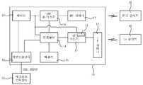
도 3은 본 발명에 따른 수동형 알에프아이디 칩을 이용하여 설정정보 변경이 가능한 능동형 RFID 태그의 구성을 나타낸 기능블록도이다.Figure 3 is a functional block diagram showing the configuration of an active RFID tag that can be changed configuration information using a passive RFID chip according to the present invention.
본 발명의 일 실시예에 따른 수동형 알에프아이디 칩을 이용하여 설정정보 변경이 가능한 능동형 RFID 태그는 UHF 송/수신기(111), LF 수신기(121), RFID 칩(131) 메모리(133), 컨트롤러(140) 및 배터리(160)를 포함한다.An active RFID tag that can change setting information using a passive RFID chip according to an embodiment of the present invention includes a UHF transmitter /
UHF 송/수신기(111)는 RFID 판독기(30)와 868~956㎒ 주파수 대역을 사용하여 무선 통신을 수행한다.The UHF transmitter /
그리고 LF 수신기(121)는 LF 송신기(40)로부터 웨이크 업 패턴 정보를 수신하며, 통상 120~140㎑의 주파수 대역을 사용하며, 웨이크 업 패턴이 저장되는 웨이크업(Wakeup) 패턴 저장부(123)를 포함한다.In addition, the
또한, RFID 칩(131)은 RFID 안테나(132)를 통해 RFID 리더기(300)와 근거리 통신을 수행하며, 13.56㎒의 주파수 대역을 사용한다.In addition, the
여기서 RFID 칩(131)은 상호유도(Inductively coupled) 방식으로 근거리 1m 이내에서 코일 안테나인 RFID 안테나(132)를 이용하여 RFID 리더기(300)로부터 제공되는 유도 에너지를 공급받아 동작한다.Here, the
그리고 RFID 칩(131)은 RFID 리더기(300)의 안테나 코일과 RFID 칩(131)의 RFID 안테나(132) 사이에 변환기 형태 결합을 기본으로 하고 있으며, 코일 사이의 거리가 0.16λ(λ는 전파의 파장)을 넘지 않을 때만 동작하며 진폭변조나 부하변조와 같은 데이터 처리방식을 이용한다.And the
또한 LF 수신기(121)는 컨트롤러(140)에 의해 설정정보 중 웨이크 업 패턴이 설정되며, LH 송신기(40)로부터 수신되는 웨이크 업 패턴과 설정된 웨이크 업 패턴을 비교하여 동일할 경우 활성화 신호를 컨트롤러(140)로 전송한다.In addition, the
그리고 메모리(133)는 RFID 칩(131)에 의해 수신된 설정정보인 웨이크 업 패턴이 저장된다. 또한, 메모리(133)에는 RFID 칩(131)에 의해 수신된 설정정보인 태그 ID도 저장될 수 있다.In addition, the
컨트롤러(140)는 슬립 상태에서 LF 수신기(121)로부터 활성화 신호가 수신되면 활성화 상태로 전환하여 UHF 송/수신기(111)를 통해 메모리(133)에 저장된 태그정보 또는 태그 ID 정보의 송/수신을 수행한 후 슬립 상태로 전환한다. 여기서, 슬립 상태란 배터리(160)로부터 전원이 차단되어 RFID 판독기(30)와의 통신을 수행하지 않는 상태를 말하며, 활성화 상태란 배터리(160)로부터 전원이 인가되어 UHF 송/수신기(111)를 통해 RFID 판독기(30)와의 통신이 가능한 상태를 말한다.When the activation signal is received from the
그 뿐만 아니라, 컨트롤러(140)는 메모리(133)에 저장된 설정정보인 웨이크 업 패턴을 LF 수신기(121)에 설정한다.In addition, the
그리고 RFID 칩(131)은 RFID 리더기(300)로부터 근거리 무선 통신을 통해 수신되는 설정정보인 웨이크 업 패턴을 메모리(133)에 저장한다. 이때, RFID 칩(131)으로부터 수신되는 설정정보는 웨이크 업 패턴뿐만 아니라 태그 ID도 수신될 수 있다.In addition, the
또한, 푸시버튼(150)은 메모리(133)에 저장된 설정정보인 웨이크 업 패턴이 LF 수신기(121)에 설정하도록 패턴설정시작신호를 컨트롤러(140)에 전달한다.In addition, the
그러면 컨트롤러(140)는 푸시버튼(150)으로부터 패턴설정시작신호가 입력됨에 따라 메모리(133)에 저장된 웨이크 업 패턴을 LF 수신기(121)에 설정한다. 여기서, 컨트롤러(140)가 LF 수신기(121)의 웨이크 업 패턴을 설정한다 라함은 메모리(133)에 저장된 웨이크업 패턴을 웨이크업 패턴 저장부(123)에 저장한다는 것이다.Then, the
한편, 컨트롤러(140)는 RFID 칩(131)에 의해 메모리(133)에 저장된 태그 ID를 태그 ID로 변경할 수 있다.
The
이러한, 본 발명에 따른 수동형 알에프아이디 칩을 이용하여 설정정보 변경이 가능한 능동형 RFID 태그에 대한 동작에 대하여 설명하기로 한다.The operation of the active RFID tag whose configuration information can be changed using the passive RFID chip according to the present invention will be described.
먼저, 능동형 RFID 태그(100)에는 생산 시 동일한 웨이크 업 패턴이 적용되고, 태그 ID는 다르게 적용되어 생산된다.First, the same wake-up pattern is applied to the
이렇게 생산된 능동형 RFID 태그(100)는 호텔 등에 의해 사용될 수 있다.The
호텔의 각 객실에는 능동형 RFID 태그(100)와 통신을 수행하기 위한 UHF 대역의 RFID 판독기(30)가 설치된다.Each room of the hotel is equipped with an
각 객실에 설치된 RFID 판독기(30)에는 능동형 RFID 태그(100)에 웨이크 업 패턴을 제공하기 위해 웨이크 업 패턴 송신기인 LF 송신기(200-1 또는 200-n)가 추가로 설치될 수 있다. 이때, LF 송신기(200-1 또는 200-n)는 각 객실에 따라 웨이크 업 패턴이 다르게 설정될 수 있다.In the
만약, 각 객실에 설치된 다수 LF 송신기(200-1 내지 200-n)의 웨이크 업 패턴이 다르게 설정되어 있을 경우, 각 객실에 대응되는 능동형 RFID 태그(100)에는 LF 송신기(200-1 내지 200n)에 대응되게 웨이크 업 패턴이 설정되어야 한다.If the wake-up pattern of the plurality of LF transmitters 200-1 to 200-n installed in each room is set differently, the
그러나 능동형 RFID 태그(100)는 생산 시 동일하게 웨이크 업 패턴이 설정되어 있기 때문에 관리자는 능동형 RFID 태그(100)의 웨이크 업 패턴을 변경해야 한다.However, since the
따라서 관리자는 능동형 RFID 태그(100)의 웨이크 업 패턴을 변경하기 위해 능동형 RFID 태그(100)를 RFID 리더기(300)에 근접시킨다.Therefore, the manager moves the
그러면, 능동형 RFID 태그(100)의 RFID 칩(131)은 RFID 리더기(300)와 무선 통신을 통해 웨이크 업 패턴을 수신하고 수신된 웨이크 업 패턴을 메모리(133)에 저장한다.Then, the
이후, 관리자가 푸시버튼(150)을 눌러 푸시버튼(150)으로부터 패턴설정시작신호가 컨트롤러(140)에 전달되면, 컨트롤러(140)는 슬립 상태에서 활성화 상태로 전환된 후 메모리(133)에 저장된 웨이크 업 패턴을 리딩한다.Thereafter, when the manager presses the
이어서, 컨트롤러(140)는 메모리(133)로부터 리딩한 웨이크 업 패턴과 LF 수신기(121)에 설정된 웨이크 업 패턴이 동일한지의 여부를 판단한다.Subsequently, the
만약, 웨이크 업 패턴이 동일하지 않으면 컨트롤러(140)는 리딩한 웨이크 업 패턴을 LF 수신기(121)에 설정함으로써 간편하게 웨이크 업 패턴을 변경할 수 있다.
If the wake-up pattern is not the same, the
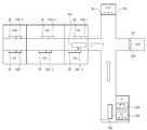
도 4는 본 발명에 따른 수동형 알에프아이디 칩을 이용하여 설정정보 변경이 가능한 능동형 RFID 태그의 실시예를 나타낸 도면이다.4 is a view showing an embodiment of an active RFID tag capable of changing setting information using a passive RFID chip according to the present invention.
도 4에 도시된 바와 같이 호텔의 각 객실에는 각각의 RFID 판독기(30)와 LF 송신기(200-1 내지 200-n 중 하나)가 각각 설치된다. 이때, LF 송신기(200-1 내지 200-n)는 각각 다른 웨이크 업 패턴이 설정된다.As shown in FIG. 4, each room of the hotel is provided with a
만약, 태그 ID의 식별이 가능한 RFID 판독기(30)와 서로 다른 웨이크 업 패턴이 설정된 다수의 LF 송신기(200-1 내지 200-n)가 설치된 호텔 복도를 능동형 RFID 태그(100)를 지닌 투숙객이 지나가면, 능동형 RFID 태그(100)의 LF 수신기(121)는 임의의 LF 송신기(200-1 내지 200-n 중 어느 하나)로부터 웨이크 업 패턴을 수신한다.If a guest with an
그러면, 능동형 RFID 태그(100)의 LF 수신기(121)는 설정된 웨이크 업 패턴과 비교하여 동일할 경우 컨트롤러(140)로 활성화 신호를 전송한다. 이때, 활성화 신호에는 RFID 판독기(30)의 ID 정보가 포함될 수 있다.Then, the
그러면 컨트롤러(140)는 활성화 상태로 전환된 후 UHF 송/수신기(111)에 배터리(160)의 전원이 공급되도록 제어한다.Then, the
이후, 컨트롤러(140)는 UHF 송/수신기(111)를 통해 태그 ID를 RFID 판독기(30)로 전송한다.Thereafter, the
그러면, RFID 판독기(30)는 수신된 능동형 RFID 태그(100)의 태그 ID가 등록되어 있을 경우 해당 객실의 문을 열수 있게 한다.
Then, the
반면에, 임의의 LF 송신기(200-1 내지 200-n 중 어느 하나)로부터 수신된 웨이크 업 패턴이 설정된 웨이크 업 패턴과 비교하여 동일하지 않을 경우 LF 수신기(121)는 컨트롤러(140)로 아무런 신호를 전송하지 않고 능동형 RFID 태그(100)의 상태를 슬립 상태로 유지한다. 따라서 능동형 RFID 태그(100)는 다른 웨이크 업 패턴에 의해 활성화 상태로 전환되지 않음에 따라 배터리(160)의 소모를 줄일 수 있다.
On the other hand, when the wake-up pattern received from any LF transmitter 200-1 to 200-n is not the same as the set wake-up pattern, the
본 발명에 따른 수동형 알에프아이디 칩을 이용하여 설정정보 변경이 가능한 능동형 알에프아이디 태그 설정정보 변경 방법에 대하여 도 5를 참조하여 설명하기로 한다.A method of changing active RFID tag setting information that can be changed using a passive RFID chip according to the present invention will be described with reference to FIG. 5.
먼저, 관리자가 웨이크 업 패턴을 수신하기 위해 능동형 RFID 태그(100)를 RFID 리더기(300)에 접근시키면, 능동형 RFID 태그(100)의 RFID 칩(131)은 RFID 리더기(300)로부터 제공되는 에너지에 의해 구동된다(S110).First, when the manager approaches the
이어서, RFID 칩(131)은 수동형 RFID 태그 ID를 RFID 리더기(300)로 전송한다(S120).Subsequently, the
RFID 칩(131)은 무선통신에 의해 RFID 리더기(300)로부터 설정정보인 웨이크 업 패턴을 수신하여 메모리(133)에 저장한다(S130). 이때, 설정정보는 능동형 RFID 태그의 ID을 포함하거나 능동형 RFID 태그의 ID일 수 있다.The
이후, 컨트롤러(140)는 메모리(133)에 저장된 웨이크 업 패턴을 리딩하여 LF 수신기(121)에 설정한다(S140). 이때, 메모리(133)에 저장된 웨이크 업 패턴을 LF 수신기(121)에 설정하는 컨트롤러(140)는 푸쉬버튼(150)으로부터 신호가 입력될 때 수행할 수도 있다.Thereafter, the
하기에서는 컨트롤러(140)가 활성화 상태에서 메모리(133)에 저장된 웨이크 업 패턴을 리딩하여 LF 수신기(121)에 설정(S140) 단계의 세부 단계에 대하여 도 6을 참조하여 설명하기로 한다.Hereinafter, detailed steps of the setting step S140 of the
먼저, 컨트롤러(140)는 슬립 상태(S141)에서 푸시버튼(150)으로부터 신호가 입력(S142)되면 활성화 상태로 전환(S143)된 후 메모리(133)에 저장된 웨이크 업 패턴을 리딩한다(S144).First, when the signal is input (S142) from the
이어서, 컨트롤러(140)는 메모리(133)에서 리딩한 웨이크 업 패턴과 LF 수신기(121)에 설정된 웨이크 업 패턴이 다른지 판단한다(S145).Subsequently, the
상기 판단단계(S142)에서 웨이크 업 패턴이 다르면(YES), 컨트롤러(140)는 메모리(133)로부터 리딩한 웨이크 업 패턴으로 LF 수신기(121)의 웨이크 업 패턴을 변경(S146)한 후 슬립 상태로 전환한다(S147).
If the wakeup pattern is different (YES) in the determination step (S142), the
전술된 상세한 설명이 여러 실시예에 적용된 바와 같이 본 발명의 기본적인 신규한 특징들을 도시하고 기술하고 언급하였지만, 예시된 시스템의 형태 및 상세 사항에 대해 본 발명의 의도를 벗어남이 없이 여러 생략, 교체 및 변경이 이 기술 분야에 숙련된 자에 의해 이루어질 수 있다는 것을 이해할 수 있을 것이다.
Although the foregoing detailed description has shown, described, and mentioned the basic novel features of the invention as applied to the various embodiments, various omissions, substitutions, and changes in the form and details of the illustrated system may be made without departing from the intention of the invention. It will be appreciated that changes may be made by those skilled in the art.
20 : 태그정보 입력장치 30 : RFID 판독기
40 : LF 송신기 100 : 능동형 RFID 태그
111 : UHF 송/수신기 112 : UHF 안테나
121 : LF 수신기 122 : LF 안테나
123 : 웨이크 업 패턴 저장부 131 : RFID 칩
132 : RFID 안테나 133 : 메모리
140 : 컨트롤러 150 : 푸시버튼
160 : 배터리 170 : 외부 연결 단자
300 : RFID 리더기20: tag information input device 30: RFID reader
40: LF transmitter 100: active RFID tag
111: UHF transmitter / receiver 112: UHF antenna
121: LF receiver 122: LF antenna
123: Wake-up pattern storage unit 131: RFID chip
132: RFID antenna 133: memory
140: controller 150: pushbutton
160: battery 170: external connection terminal
300: RFID Reader
Claims (7)
Translated fromKorean웨이크 업 패턴이 저장되는 메모리;
LF 수신기의 웨이크-업 패턴을 상기 메모리에 저장된 웨이크-업 패턴으로 변경하는 컨트롤러; 및
리더기로부터 무선통신에 의해 수신되는 웨이크 업 패턴을 상기 메모리에 저장하는 RFID 칩을 포함하여 이루어지되,
상기 RFID 칩은 리더기로부터 태그 ID를 수신받아 상기 메모리의 태그 ID 저장영역에 저장하는 기능을 더 포함하는 것을 특징으로 하는 수동형 알에프아이디 칩을 이용하여 설정정보 변경이 가능한 능동형 RFID 태그.
In an active RFID tag,
A memory in which a wake up pattern is stored;
A controller for changing a wake-up pattern of an LF receiver to a wake-up pattern stored in the memory; And
Including the RFID chip to store in the memory the wake-up pattern received by the wireless communication from the reader,
The RFID chip may receive a tag ID from a reader and store the tag ID in a tag ID storage area of the memory. The RFID tag may be configured to change setting information using a passive RFID chip.
상기 메모리에 저장된 웨이크 업 패턴을 LF 수신기의 웨이크 업 패턴 저장부에 변경하도록 하는 신호를 상기 컨트롤러에 전달하는 푸시버튼을 더 포함하되,
상기 컨트롤러는 상기 푸시버튼으로부터 신호가 입력되면 상기 메모리에 저장된 웨이크 업 패턴을 상기 LF 수신기의 웨이크 업 패턴 저장부에 저장하는 것을 특징으로 하는 수동형 알에프아이디 칩을 이용하여 설정정보 변경이 가능한 능동형 RFID 태그.
The method of claim 2,
Further comprising a push button for transmitting a signal to the controller to change the wake-up pattern stored in the memory to the wake-up pattern storage of the LF receiver,
When the controller receives a signal from the pushbutton, the controller stores the wakeup pattern stored in the memory in the wakeup pattern storage unit of the LF receiver. .
RFID 칩이 리더기로부터 근거리 무선통신에 의해 수신되는 웨이크 업 패턴을 메모리에 저장하는 단계;
상기 RFID 칩이 리더기로부터 태그 ID를 수신받아 상기 메모리의 태그 ID 저장영역에 저장하는 단계 및
컨트롤러가 상기 메모리에 저장된 웨이크 업 패턴을 리딩하여 해당 설정영역에 설정하는 단계를 포함하여 이루어진 것을 특징으로 하는 설정정보 변경이 가능한 능동형 알에프아이디 태그 설정정보 변경 방법.
In the method of changing the setting information of the active RFID tag,
Storing, by the RFID chip, a wake-up pattern received by the near field communication from the reader in a memory;
Receiving, by the RFID chip, a tag ID from a reader, and storing the tag ID in a tag ID storage area of the memory;
And a controller reading the wake-up pattern stored in the memory and setting the wake-up pattern in a corresponding setting area.
상기 컨트롤러가 상기 메모리에 저장된 웨이크 업 패턴을 리딩하여 해당 설정영역에 설정하는 단계는,
푸쉬버튼으로부터 신호가 입력되면 수행하는 것을 특징으로 하는 수동형 알에프아이디 칩을 이용하여 설정정보 변경이 가능한 능동형 알에프아이디 태그 설정정보 변경 방법.
The method of claim 4, wherein
The controller may read the wake-up pattern stored in the memory and set the wake-up pattern in the corresponding setting area.
A method for changing active RFID tag setting information using a passive RFID chip, which is performed when a signal is input from a push button.
상기 컨트롤러는 상기 푸시버튼으로부터 신호가 입력되면 활성화 상태로 전환된 후 상기 메모리에 저장된 웨이크 업 패턴을 리딩하는 단계;
상기 컨트롤러가 상기 메모리에서 리딩한 웨이크 업 패턴과 LF 수신기에 설정된 웨이크 업 패턴이 동일하지를 판단하는 단계; 및
상기 판단단계에서 웨이크 업 패턴이 동일하지 않으면, 상기 컨트롤러는 리딩한 웨이크 업 패턴을 상기 LF 수신기에 설정한 후 슬립 상태로 전환하는 단계를 포함하는 수동형 알에프아이디 칩을 이용하여 설정정보 변경이 가능한 능동형 알에프아이디 태그 설정정보 변경 방법.
6. The method of claim 5,
Reading, by the controller, a wake up pattern stored in the memory after being switched to an active state when a signal is input from the pushbutton;
Determining, by the controller, that the wake-up pattern read from the memory and the wake-up pattern set in the LF receiver are not the same; And
If the wake-up pattern is not the same in the determination step, the controller sets the read-up wake-up pattern to the LF receiver and then transitions to a sleep state. The active type may change the setting information using a passive RFID chip. How to change RFID tag setting information.
Priority Applications (1)
| Application Number | Priority Date | Filing Date | Title |
|---|---|---|---|
| KR1020100134152AKR101148768B1 (en) | 2010-12-24 | 2010-12-24 | Active rfid tag changing setup information using passive rfid chip and the active rfid tag setup method thereof |
Applications Claiming Priority (1)
| Application Number | Priority Date | Filing Date | Title |
|---|---|---|---|
| KR1020100134152AKR101148768B1 (en) | 2010-12-24 | 2010-12-24 | Active rfid tag changing setup information using passive rfid chip and the active rfid tag setup method thereof |
Publications (1)
| Publication Number | Publication Date |
|---|---|
| KR101148768B1true KR101148768B1 (en) | 2012-05-24 |
Family
ID=46272513
Family Applications (1)
| Application Number | Title | Priority Date | Filing Date |
|---|---|---|---|
| KR1020100134152AExpired - Fee RelatedKR101148768B1 (en) | 2010-12-24 | 2010-12-24 | Active rfid tag changing setup information using passive rfid chip and the active rfid tag setup method thereof |
Country Status (1)
| Country | Link |
|---|---|
| KR (1) | KR101148768B1 (en) |
Cited By (2)
| Publication number | Priority date | Publication date | Assignee | Title |
|---|---|---|---|---|
| CN112784944A (en)* | 2020-12-24 | 2021-05-11 | 阳光凯讯(北京)科技有限公司 | Electronic tag based on motion sensor and radio frequency identification technology and energy-saving method thereof |
| CN114707525A (en)* | 2022-03-30 | 2022-07-05 | 上海远铮科技发展有限公司 | Electronic luggage tag, radio frequency read-write equipment and awakening method |
Citations (4)
| Publication number | Priority date | Publication date | Assignee | Title |
|---|---|---|---|---|
| JP2005209002A (en) | 2004-01-23 | 2005-08-04 | Ricoh Co Ltd | IC tag reader / writer and apparatus having IC tag reader / writer |
| KR100869776B1 (en) | 2007-06-15 | 2008-11-21 | 아시아나아이디티 주식회사 | Low power consumption active tag and reader for always-wake and long-distance transmission |
| KR20100089433A (en)* | 2009-02-04 | 2010-08-12 | 주식회사 에이치앤테크 | Electronic tag including the mode convertible function and base station device using the tag |
| KR20100121286A (en)* | 2009-05-08 | 2010-11-17 | 부산대학교 산학협력단 | Active rfid systems and method for controlling tag wake up the same |
- 2010
- 2010-12-24KRKR1020100134152Apatent/KR101148768B1/ennot_activeExpired - Fee Related
Patent Citations (4)
| Publication number | Priority date | Publication date | Assignee | Title |
|---|---|---|---|---|
| JP2005209002A (en) | 2004-01-23 | 2005-08-04 | Ricoh Co Ltd | IC tag reader / writer and apparatus having IC tag reader / writer |
| KR100869776B1 (en) | 2007-06-15 | 2008-11-21 | 아시아나아이디티 주식회사 | Low power consumption active tag and reader for always-wake and long-distance transmission |
| KR20100089433A (en)* | 2009-02-04 | 2010-08-12 | 주식회사 에이치앤테크 | Electronic tag including the mode convertible function and base station device using the tag |
| KR20100121286A (en)* | 2009-05-08 | 2010-11-17 | 부산대학교 산학협력단 | Active rfid systems and method for controlling tag wake up the same |
Cited By (3)
| Publication number | Priority date | Publication date | Assignee | Title |
|---|---|---|---|---|
| CN112784944A (en)* | 2020-12-24 | 2021-05-11 | 阳光凯讯(北京)科技有限公司 | Electronic tag based on motion sensor and radio frequency identification technology and energy-saving method thereof |
| CN112784944B (en)* | 2020-12-24 | 2024-03-22 | 阳光凯讯(北京)科技有限公司 | Electronic tag based on motion sensor and radio frequency identification technology and energy-saving method thereof |
| CN114707525A (en)* | 2022-03-30 | 2022-07-05 | 上海远铮科技发展有限公司 | Electronic luggage tag, radio frequency read-write equipment and awakening method |
Similar Documents
| Publication | Publication Date | Title |
|---|---|---|
| US20100295663A1 (en) | Methods and systems for utilizing backscattering techniques in wireless applications | |
| JP5491331B2 (en) | Communication mode setting device | |
| US20170243420A1 (en) | Electric lock adapted to be activated by a mobile phone and method thereof | |
| JP2010185186A (en) | Keyless entry system | |
| KR20100096007A (en) | Radio communication apparatus, radio communication method and program | |
| JP2012512463A (en) | Compatible or exclusive RFID tag communication and query rounds | |
| RU2013103453A (en) | METHOD AND DEVICE FOR PREVENTING LOSS OF SUBJECT AND QUICK SEARCH FOR SUBJECT | |
| US9204485B2 (en) | Network node for a wireless sensor network | |
| CN104737459A (en) | Device detection using load modulation in near-field communications | |
| WO2004013652A1 (en) | Interrogator of moving body identification device | |
| KR101148768B1 (en) | Active rfid tag changing setup information using passive rfid chip and the active rfid tag setup method thereof | |
| KR20070056818A (en) | Radio Frequency Recognition System | |
| JP2002015288A (en) | RFID multi-purpose interrogator | |
| KR101001681B1 (en) | Active RFI system and its tag wake up control method | |
| JP4336379B2 (en) | RFID carrier sense method and RFID system using the same | |
| US20070298743A1 (en) | Data communication device for wireless microphone | |
| KR101532965B1 (en) | Passive rfid chip and communication apparatus having passive rfid chip | |
| CN205647629U (en) | Hyperfrequency radio -frequency identification reader based on cell -phone | |
| JP5084611B2 (en) | Mobile object management system and responder | |
| KR20070056816A (en) | Radio Frequency Recognition System | |
| KR100768101B1 (en) | Power Control Method for Mobile RFID Reader and RFID Reader for being embodied it | |
| JP2007174130A (en) | Hybrid type soft ID tag with sensor function for multi-communication system | |
| JP5329927B2 (en) | Entrance / exit management system | |
| CN107704909B (en) | High-frequency multi-protocol high-power reader-writer for radio frequency identification | |
| JP4902363B2 (en) | RFID tag and transmission / reception method in RFID tag |
Legal Events
| Date | Code | Title | Description |
|---|---|---|---|
| A201 | Request for examination | ||
| PA0109 | Patent application | St.27 status event code:A-0-1-A10-A12-nap-PA0109 | |
| PA0201 | Request for examination | St.27 status event code:A-1-2-D10-D11-exm-PA0201 | |
| D13-X000 | Search requested | St.27 status event code:A-1-2-D10-D13-srh-X000 | |
| D14-X000 | Search report completed | St.27 status event code:A-1-2-D10-D14-srh-X000 | |
| PE0902 | Notice of grounds for rejection | St.27 status event code:A-1-2-D10-D21-exm-PE0902 | |
| E13-X000 | Pre-grant limitation requested | St.27 status event code:A-2-3-E10-E13-lim-X000 | |
| P11-X000 | Amendment of application requested | St.27 status event code:A-2-2-P10-P11-nap-X000 | |
| P13-X000 | Application amended | St.27 status event code:A-2-2-P10-P13-nap-X000 | |
| E701 | Decision to grant or registration of patent right | ||
| PE0701 | Decision of registration | St.27 status event code:A-1-2-D10-D22-exm-PE0701 | |
| GRNT | Written decision to grant | ||
| PR0701 | Registration of establishment | St.27 status event code:A-2-4-F10-F11-exm-PR0701 | |
| PR1002 | Payment of registration fee | St.27 status event code:A-2-2-U10-U11-oth-PR1002 Fee payment year number:1 | |
| PG1601 | Publication of registration | St.27 status event code:A-4-4-Q10-Q13-nap-PG1601 | |
| FPAY | Annual fee payment | Payment date:20150507 Year of fee payment:4 | |
| PR1001 | Payment of annual fee | St.27 status event code:A-4-4-U10-U11-oth-PR1001 Fee payment year number:4 | |
| FPAY | Annual fee payment | Payment date:20160608 Year of fee payment:5 | |
| PR1001 | Payment of annual fee | St.27 status event code:A-4-4-U10-U11-oth-PR1001 Fee payment year number:5 | |
| P22-X000 | Classification modified | St.27 status event code:A-4-4-P10-P22-nap-X000 | |
| FPAY | Annual fee payment | Payment date:20170516 Year of fee payment:6 | |
| PR1001 | Payment of annual fee | St.27 status event code:A-4-4-U10-U11-oth-PR1001 Fee payment year number:6 | |
| PN2301 | Change of applicant | St.27 status event code:A-5-5-R10-R13-asn-PN2301 St.27 status event code:A-5-5-R10-R11-asn-PN2301 | |
| P22-X000 | Classification modified | St.27 status event code:A-4-4-P10-P22-nap-X000 | |
| LAPS | Lapse due to unpaid annual fee | ||
| PC1903 | Unpaid annual fee | St.27 status event code:A-4-4-U10-U13-oth-PC1903 Not in force date:20180517 Payment event data comment text:Termination Category : DEFAULT_OF_REGISTRATION_FEE | |
| PC1903 | Unpaid annual fee | St.27 status event code:N-4-6-H10-H13-oth-PC1903 Ip right cessation event data comment text:Termination Category : DEFAULT_OF_REGISTRATION_FEE Not in force date:20180517 |