KR101147995B1 - Pedaling assist transmission - Google Patents
Pedaling assist transmissionDownload PDFInfo
- Publication number
- KR101147995B1 KR101147995B1KR1020090129064AKR20090129064AKR101147995B1KR 101147995 B1KR101147995 B1KR 101147995B1KR 1020090129064 AKR1020090129064 AKR 1020090129064AKR 20090129064 AKR20090129064 AKR 20090129064AKR 101147995 B1KR101147995 B1KR 101147995B1
- Authority
- KR
- South Korea
- Prior art keywords
- gear
- ring
- unit
- pole
- driving unit
- Prior art date
- Legal status (The legal status is an assumption and is not a legal conclusion. Google has not performed a legal analysis and makes no representation as to the accuracy of the status listed.)
- Active
Links
- 230000005540biological transmissionEffects0.000titleclaimsabstractdescription85
- 230000009467reductionEffects0.000claimsdescription32
- 230000001133accelerationEffects0.000claimsdescription22
- 238000000034methodMethods0.000claimsdescription5
- 230000000452restraining effectEffects0.000claimsdescription2
- 241000282472Canis lupus familiarisSpecies0.000claims1
- 238000003825pressingMethods0.000description24
- 230000008859changeEffects0.000description2
- 238000010586diagramMethods0.000description2
- 230000008569processEffects0.000description2
- 230000005856abnormalityEffects0.000description1
- 230000009471actionEffects0.000description1
- 230000008901benefitEffects0.000description1
- 230000000903blocking effectEffects0.000description1
- 238000010276constructionMethods0.000description1
- 230000003247decreasing effectEffects0.000description1
- 230000000694effectsEffects0.000description1
- 230000005484gravityEffects0.000description1
- 230000002093peripheral effectEffects0.000description1
- 238000005096rolling processMethods0.000description1
Images


Classifications
- B—PERFORMING OPERATIONS; TRANSPORTING
- B62—LAND VEHICLES FOR TRAVELLING OTHERWISE THAN ON RAILS
- B62M—RIDER PROPULSION OF WHEELED VEHICLES OR SLEDGES; POWERED PROPULSION OF SLEDGES OR SINGLE-TRACK CYCLES; TRANSMISSIONS SPECIALLY ADAPTED FOR SUCH VEHICLES
- B62M6/00—Rider propulsion of wheeled vehicles with additional source of power, e.g. combustion engine or electric motor
- B62M6/40—Rider propelled cycles with auxiliary electric motor
- B62M6/60—Rider propelled cycles with auxiliary electric motor power-driven at axle parts
- B62M6/65—Rider propelled cycles with auxiliary electric motor power-driven at axle parts with axle and driving shaft arranged coaxially
- B—PERFORMING OPERATIONS; TRANSPORTING
- B62—LAND VEHICLES FOR TRAVELLING OTHERWISE THAN ON RAILS
- B62M—RIDER PROPULSION OF WHEELED VEHICLES OR SLEDGES; POWERED PROPULSION OF SLEDGES OR SINGLE-TRACK CYCLES; TRANSMISSIONS SPECIALLY ADAPTED FOR SUCH VEHICLES
- B62M11/00—Transmissions characterised by the use of interengaging toothed wheels or frictionally-engaging wheels
- B62M11/04—Transmissions characterised by the use of interengaging toothed wheels or frictionally-engaging wheels of changeable ratio
- B62M11/14—Transmissions characterised by the use of interengaging toothed wheels or frictionally-engaging wheels of changeable ratio with planetary gears
- B62M11/16—Transmissions characterised by the use of interengaging toothed wheels or frictionally-engaging wheels of changeable ratio with planetary gears built in, or adjacent to, the ground-wheel hub
- B—PERFORMING OPERATIONS; TRANSPORTING
- B62—LAND VEHICLES FOR TRAVELLING OTHERWISE THAN ON RAILS
- B62M—RIDER PROPULSION OF WHEELED VEHICLES OR SLEDGES; POWERED PROPULSION OF SLEDGES OR SINGLE-TRACK CYCLES; TRANSMISSIONS SPECIALLY ADAPTED FOR SUCH VEHICLES
- B62M6/00—Rider propulsion of wheeled vehicles with additional source of power, e.g. combustion engine or electric motor
- B62M6/40—Rider propelled cycles with auxiliary electric motor
- B62M6/45—Control or actuating devices therefor
- B—PERFORMING OPERATIONS; TRANSPORTING
- B62—LAND VEHICLES FOR TRAVELLING OTHERWISE THAN ON RAILS
- B62M—RIDER PROPULSION OF WHEELED VEHICLES OR SLEDGES; POWERED PROPULSION OF SLEDGES OR SINGLE-TRACK CYCLES; TRANSMISSIONS SPECIALLY ADAPTED FOR SUCH VEHICLES
- B62M9/00—Transmissions characterised by use of an endless chain, belt, or the like
- B62M9/04—Transmissions characterised by use of an endless chain, belt, or the like of changeable ratio
- B62M9/06—Transmissions characterised by use of an endless chain, belt, or the like of changeable ratio using a single chain, belt, or the like
- B62M9/10—Transmissions characterised by use of an endless chain, belt, or the like of changeable ratio using a single chain, belt, or the like involving different-sized wheels, e.g. rear sprocket chain wheels selectively engaged by the chain, belt, or the like
- B62M9/12—Transmissions characterised by use of an endless chain, belt, or the like of changeable ratio using a single chain, belt, or the like involving different-sized wheels, e.g. rear sprocket chain wheels selectively engaged by the chain, belt, or the like the chain, belt, or the like being laterally shiftable, e.g. using a rear derailleur
- B62M9/121—Rear derailleurs
- B62M9/123—Rear derailleurs changing gears automatically
Landscapes
- Engineering & Computer Science (AREA)
- Chemical & Material Sciences (AREA)
- Combustion & Propulsion (AREA)
- Transportation (AREA)
- Mechanical Engineering (AREA)
- Structure Of Transmissions (AREA)
- Retarders (AREA)
- Mechanical Control Devices (AREA)
Abstract
Translated fromKorean
Description
Translated fromKorean본 발명은 페달링 어시스트 변속기에 관한 것으로서 특히, 탑승자가 페달에 가하는 답력을 감지하여 이 답력에 따라 모터를 구동시키는 모터 구동력을 능동적으로 제어하기 위한 장치에 관한 것으로써, 탑승자의 의지에 따라 별도의 조작 없이도 페달링에 의해 모터를 통한 가속을 손쉽게 실시할 수 있을 뿐 아니라, 그 내부에서 다단 유성기어를 통한 다단 변속 또한 자체적으로 이루어져 주행 여건에 따라 적절한 토크와 속도를 얻을 수 있는 장치에 관한 것이다.BACKGROUND OF THE INVENTION 1. Field of the Invention The present invention relates to a pedaling assist transmission. More particularly, the present invention relates to a device for actively controlling a motor driving force that senses a pedaling force applied to a pedal and drives a motor according to the pedaling power. The present invention relates to a device that can easily perform acceleration through a motor by pedaling without using it, and also, by using a multi-stage planetary gear, also adopts a multi-stage shift gear within itself to obtain proper torque and speed according to driving conditions.
일반적으로 자전거는 탑승자의 인력에 의해 페달을 구르는 것으로 바퀴를 회전시켜 주행하는 운송수단이다.In general, a bicycle is a vehicle for driving by rotating a wheel by rolling a pedal by an occupant's manpower.
이와 같이 인력에 의해 주행 가능한 자전거에 충전 가능한 배터리와 전원 공급에 따라 회전하는 모터를 추가 구성한 전동식 자전거가 개발되고 있다.As such, an electric bicycle has been developed in which a battery that can be charged by a manpower and a motor that rotates according to a power supply are added.
전동식 자전거는 가속 조작에 따라 모터의 회전속도를 가변 제어함으로써, 저속에서 고속까지 자전거의 주행 속도를 다양하게 제어할 수 있는 것이다.The electric bicycle can variably control the running speed of the bicycle from low speed to high speed by variably controlling the rotation speed of the motor according to the acceleration operation.
그러나, 단순히 모터의 회전력을 자전거의 구동원으로 이용할 경우 주행 환경에 따른 적절한 구동 토크를 얻기 어렵기 때문에 변속기를 부가해야 하며, 최근 들어 전동식 자전거의 허브 내에 변속기와 모터를 함께 내장한 구조가 개발되고 있는 실정이다.However, when simply using the rotational power of the motor as a driving source of the bicycle, it is difficult to obtain a proper driving torque according to the driving environment. Therefore, a transmission must be added. It is true.
상술한 바와 같은 종래의 변속기에는 모터에 의한 전동력(電動力)과 탑승자의 인력(人力), 즉 전동식 자전거의 페달에 가하는 답력(이하 페달링(pedaling)이라 한다)이 각각 입력되면, 입력된 전동력과 인력 중 더 빠르게 회전하는 어느 하나만이 출력되는 것으로, 이들은 서로 독립적으로 구동하게 되는 것이다.In the conventional transmission as described above, when the electric force by the motor and the manpower of the occupant, that is, the pedal force (hereinafter referred to as pedaling) applied to the pedal of the electric bicycle, are input, Only one of the faster rotation of the attraction force is output, they are driven independently of each other.
이에 따라, 전동식 자전거의 탑승자는 별도의 가속조작수단을 조작하여 모터의 회전속도를 가감시키는 동시에, 발로는 페달링을 실시함으로써, 탑승자가 원하는 주행 속도를 얻고 있는 실정으로, 탑승자는 전동력과 인력을 이원적으로 제어해야 한다는 기술적인 문제점이 있었다.Accordingly, the occupant of the electric bicycle operates a separate acceleration operation means to increase or decrease the rotational speed of the motor, and pedaling by the foot to obtain a desired driving speed. There was a technical problem that the control must be controlled.
본 발명은 상기의 문제점을 해소하기 위한 것으로, 입력되는 전동력과 인력 중 더 빠른 회전을 선택적으로 변속 출력시키는 변속기에 있어서 탑승자가 페달에 가하는 답력에 따라 전동력을 능동적으로 증속시킬 수 있음으로써, 탑승자의 의지에 따라 별도의 조작 없이도 페달링에 의해 모터를 통한 가속을 손쉽게 실시할 수 있을 뿐 아니라, 그 내부에서 다단 유성기어를 통한 다단 변속 또한 자체적으로 이루어져 주행 여건에 따라 적절한 토크와 속도를 얻을 수 있도록 하는 페달링 어시스트 변속기를 제공하고자 한다.The present invention is to solve the above problems, in the transmission for selectively outputting a faster rotation of the input power and the manpower can be actively increased the electric power according to the pedaling force applied to the pedals, According to the will, it is not only possible to easily accelerate the motor by pedaling without additional operation, but also to make the multi-stage shifting through the multi-stage planetary gear inside itself so that appropriate torque and speed can be obtained according to the driving conditions. To provide a pedaling assist transmission.
이러한 본 발명은 차체프레임에 고정되는 고정축과; 상기 고정축의 외주에 회전 가능하게 지지되어 종동력을 출력시키는 허브쉘과; 모터의 회전으로 구동하는 전동력구동부와; 탑승자의 페달링 구동력을 입력받아 구동하는 인력구동부와; 상기 전동력구동부 및 인력구동부와 상기 허브쉘 사이에 마련되어 상기 전동력구동부와 상기 인력구동부 중 고속으로 회전하는 어느 하나의 출력을 선택적으로 상기 허브쉘에 전달하는 선택출력부와; 외부로부터 상기 인력구동부에 입력되는 구동력을 검출하는 토크센서와; 상기 토크센서로부터 검출된 구동력에 따라 상기 모터의 회전 속도를 제어하는 제어부로 구성함으로써 달성된다.The present invention is a fixed shaft fixed to the vehicle body frame; A hub shell rotatably supported on an outer circumference of the fixed shaft to output a driven force; An electric power driving unit driven by the rotation of the motor; A manpower driving unit which receives and drives the pedaling driving force of the occupant; A selective output unit provided between the electric force driving unit and the manpower driving unit and the hub shell to selectively transmit any one of the electric power driving unit and the manpower driving unit to rotate at a high speed to the hub shell; A torque sensor detecting a driving force input from the outside to the attraction driving unit; It is achieved by configuring a control unit for controlling the rotational speed of the motor in accordance with the driving force detected from the torque sensor.
이때, 상기 전동력구동부에는, 상기 모터의 회전축 외주에 치합하는 감속기 어와; 상기 감속기어의 외주에 치합하여 상기 선택출력부에 회전력을 전달하는 내기어로 이루어진 전동력감속부가 마련되는 것이 바람직하다.At this time, the electric power drive unit, a reduction gear geared to the outer periphery of the rotating shaft of the motor; It is preferable that an electric force reduction unit made of an inner gear which is engaged with the outer circumference of the reduction gear and transmits rotational force to the selection output unit is provided.
그리고, 상기 인력구동부에는, 탑승자의 페달링 구동력을 입력받아 회전하는 스프라켓과; 상기 스프라켓과 일체를 이루어 회전하는 캐리어와; 상기 캐리어에 회전 가능하게 지지되는 유성기어와; 상기 유성기어의 내주에 치합하는 태양기어와; 상기 유성기어의 외주에 치합하는 동시에 그 외주가 상기 선택출력부에 회전력을 전달하는 링기어로 이루어진 인력가속부가 마련될 수도 있고,And, the manpower drive unit, the sprocket for receiving the pedaling driving force of the occupant and rotates; A carrier rotating integrally with the sprocket; Planetary gears rotatably supported by the carrier; A sun gear meshing with an inner circumference of the planetary gear; At the same time as the outer peripheral of the planetary gear and the outer periphery may be provided with a manpower acceleration consisting of a ring gear for transmitting a rotational force to the selection output,
상기 인력구동부에는, 탑승자의 페달링 구동력을 입력받아 회전하는 스프라켓과; 상기 스프라켓과 일체를 이루어 회전하는 링기어와; 상기 링기어의 내주에 치합하는 유성기어와; 상기 유성기어의 내주에 치합하는 태양기어와; 상기 유성기어를 회전 가능하게 지지하는 동시에 상기 선택출력부에 회전력을 전달하는 캐리어로 이루어진 인력감속부가 마련될 수도 있다.The manpower drive unit, the sprocket for receiving the pedaling driving force of the occupant to rotate; A ring gear rotating integrally with the sprocket; A planetary gear meshing with an inner circumference of the ring gear; A sun gear meshing with an inner circumference of the planetary gear; A manpower reduction unit may be provided that includes a carrier for rotatably supporting the planetary gear and transmitting rotational force to the selection output unit.
이때, 상기 태양기어와 상기 고정축 사이에 상기 토크센서가 위치하는 것이 바람직하다.At this time, the torque sensor is preferably located between the sun gear and the fixed shaft.
또한, 상기 선택출력부와 상기 허브쉘 사이에는, 상기 전동력구동부 또는 상기 인력구동부 중 고속으로 회전하는 어느 하나의 출력을 선택적으로 전달받아 회전하는 변속 캐리어와, 상기 변속 캐리어에 자전 가능하게 지지되는 변속 유성기어와, 상기 변속 유성기어의 외주에 치합하여 상기 허브쉘에 회전력을 전달하는 변속 링기어와, 상기 변속 유성기어의 내주에 치합하는 변속 태양기어와, 상기 변속 캐리어의 회전을 상기 변속 링기어에 선택적으로 전달하는 클러치수단으로 이루어진 변속부와; 상기 변속 태양기어의 회전을 선택적으로 구속하는 변속제어부가 추가 구성되는 것이 양호하다.In addition, between the selection output unit and the hub shell, a shift carrier for selectively receiving any one of the electric power driving unit or the manpower driving unit to rotate at high speed to rotate, and a shift supported by the shift carrier rotatably A planetary gear, a gearshift ring gear that is engaged with the outer circumference of the shifting planetary gear to transmit rotational force to the hub shell, a shifting sun gear that engages with the inner circumference of the shifting planetary gear, and a rotation of the shift carrier gear. A transmission portion made of a clutch means for selectively transmitting to; Preferably, a shift control unit is further configured to selectively restrict rotation of the shift sun gear.
이때, 상기 변속 유성기어는 1단 또는 2단 이상의 다단 변속 유성기어로 이루어지고, 상기 변속 태양기어는 상기 다단 변속 유성기어의 단수에 대응하여 한 개 또는 다수 개 마련되는 것이 바람직하다.In this case, the shift planetary gear is composed of one or two or more stages of the multi-speed planetary gear, it is preferable that one or more gears corresponding to the number of stages of the multi-speed planetary gear.
그리고, 상기 변속제어부는 각각의 상기 변속 태양기어 내주면에 형성된 래칫톱니에 선택적으로 치합하는 폴과; 누름편이 형성되어 회전에 따라 상기 폴의 돌출을 각각 제어하는 폴 제어링과; 상기 폴 제어링에 연결되어 변속케이블의 인출에 따라 회전하는 레버링을 포함하는 것이 적절하다.The shift control unit may include: a pawl selectively engaged with a ratchet tooth formed on an inner circumferential surface of each of the shift sun gears; A pole control ring having a pressing piece to control the protrusion of the pole according to rotation; It is appropriate to include a lever ring which is connected to the pole control ring and rotates when the shifting cable is pulled out.
여기에서, 상기 변속제어부에는 상기 전동력구동부 또는 상기 인력구동부에 의해 주행 중인 상태에서도 쉽게 변속이 이루어지도록 하는 강제복귀수단이 더 마련된 것이 가장 바람직하다.Here, it is most preferable that the shift control unit further includes a forced return means for easily shifting even when the vehicle is driven by the electric power drive unit or the manpower drive unit.
마지막으로, 상기 강제복귀수단은, 상기 폴 제어링의 옆에 미끄럼링을 배치하고, 이 미끄럼링과 폴 제어링의 외주면과 맞닿는 강제복귀폴을 링기어의 내측과 접속되도록 장착하여 달성되는 것이 가장 바람직하다.Finally, the forced return means is achieved by arranging a sliding ring next to the pole control ring and mounting a forced return pole contacting the outer circumferential surface of the sliding ring and the pole control ring to be connected to the inner side of the ring gear. desirable.
이상과 같은 본 발명은 입력되는 전동력과 인력 중 더 빠른 회전을 선택적으로 변속 출력시키는 변속기에 있어서 탑승자가 페달에 가하는 답력에 따라 전동력을 능동적으로 증속시킬 수 있음으로써, 탑승자의 의지에 따라 별도의 조작 없이도 페달링에 의해 모터를 통한 가속을 손쉽게 실시할 수 있을 뿐 아니라, 그 내부에서 다단 유성기어를 통한 다단 변속 또한 자체적으로 이루어져 주행 여건에 따라 적절한 토크와 속도를 얻을 수 있는 발명인 것이다.As described above, the present invention can actively increase the electric power according to the pedaling force applied by the occupant to the pedal in a transmission for selectively shifting and outputting a faster rotation among the input electric force and the manpower, so as to separately operate according to the will of the occupant. Without being able to easily accelerate the motor by pedaling, the multi-stage shifting through the multi-stage planetary gear is also made in itself, so that the proper torque and speed can be obtained according to the driving conditions.
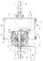
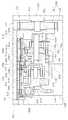
도 1은 본 발명의 페달링 어시스트 변속기에 대한 제1실시예를 도시하는 단면도이며, 도 2는 본 발명의 페달링 어시스트 변속기에 대한 제2실시예를 도시하는 단면도이다.Fig. 1 is a sectional view showing a first embodiment of a pedaling assist transmission of the present invention, and Fig. 2 is a sectional view showing a second embodiment of a pedaling assist transmission of the present invention.
그리고, 도 3은 본 발명의 페달링 어시스트 변속기에 대한 제3실시예를 도시하는 단면도이고, 도 4는 도 3에 있어서 A부분에 대한 확대도이다.3 is a sectional view showing a third embodiment of the pedaling assist transmission of the present invention, and FIG. 4 is an enlarged view of portion A in FIG.
또한, 도 5는 본 발명의 페달링 어시스트 변속기에 대한 제3실시예에 있어서 변속부 및 변속제어부에 대한 분해사시도이고, 도 6은 본 발명의 페달링 어시스트 변속기에 대한 제3실시예에 있어서 변속부 및 변속제어부에 대한 사시도이다.FIG. 5 is an exploded perspective view of a transmission unit and a shift control unit in a third embodiment of the pedaling assist transmission of the present invention, and FIG. 6 is a transmission part and a third embodiment in the pedaling assist transmission of the present invention. A perspective view of the shift control unit.
또한, 도 7 내지 도 11은 본 발명의 페달링 어시스트 변속기에 대한 제3실시예에 있어서 변속제어부 및 강제복귀수단의 작동예를 도시하는 횡단면도이다.7 to 11 are cross sectional views showing examples of the operation of the shift control unit and the forced return means in the third embodiment of the pedaling assist transmission of the present invention.
본 발명의 페달링 어시스트 변속기는 고정축(100) 상에 전동력구동부(300)와 인력구동부(400)가 마련되되, 탑승자의 페달링을 구동력으로 하는 상기 인력구동부(400)에 토크센서(600)가 마련되어, 이 토크센서(600)를 통해 검출한 값에 따라 제어부가 상기 전동력구동부(300)에 마련된 모터(310)의 회전을 제어하여, 선택출력부(500)가 상기 전동력구동부(300)와 상기 인력구동부(400) 중 고속으로 회전하 는 어느 하나를 허브쉘(200)로 출력시킬 수 있음으로써, 탑승자가 페달에 가하는 답력과 함께 모터(310)의 회전력을 보조받아 적은 힘으로도 원하는 토크나 속도를 손쉽게 얻을 수 있는 것을 그 기술상의 기본 특징으로 한다.The pedaling assist transmission of the present invention is provided with the electric
본 발명의 페달링 어시스트 변속기는 상기 인력구동부(400) 내에서의 가속 또는 감속 여부에 따라 두 가지로 분류되어, 가속의 경우를 제1실시예로 이하에서 설명하고, 감속의 경우를 제2실시예로 이하에서 설명한다.The pedaling assist transmission of the present invention is classified into two types according to acceleration or deceleration in the
또한, 탑승자의 변속레버(840) 조작에 따라 변속을 실시하는 변속부(700) 및 변속제어부(800)의 유무에 따라 다시 두 가지로 분류되는데, 이하에서는 상기 인력구동부(400)에서 가속이 실시되는 제1실시예에 상기 변속부(700) 및 변속제어부(800)가 부가된 것을 이하에서 제3실시예로 설명하고, 상기 인력구동부(400)에서 감속이 실시되는 제2실시예에 상기 변속부(700) 및 변속제어부(800)가 부가된 것의 실시예에 대한 설명은 중복되는 것으로 생략한다.In addition, according to the presence of the shifting
이하, 본 발명의 실시예를 첨부 도면을 참조하여 상세히 설명하면 다음과 같다.Hereinafter, embodiments of the present invention will be described in detail with reference to the accompanying drawings.
- 제1실시예First embodiment
우선, 도 1에 도시한 바와 같이 인력구동부(400)에서 가속이 수행되는 본 발명의 제1실시예에 있어서, 고정축(100)은 자전거의 몸체인 차체프레임에 그 양단이 회전 불가능하게 고정 지지되어 중심 뼈대 역할을 하는 것으로, 도시한 바와 같이 양측으로 구분되어, 도면상 좌측의 전동력측 고정축(110)에는 그 외주에 이하에서 설명할 전동력구동부(300)가 위치하게 되며, 도면상 우측의 인력측 고정축(120)에는 그 외주에 이하에서 설명할 인력구동부(400)가 위치하게 되는 것이다.First, as shown in FIG. 1, in the first embodiment of the present invention in which acceleration is performed in the
그리고, 허브쉘(200)은 종동력을 출력시키는 구성요소로, 예를 들어 자전거의 구동륜 중앙에 위치하여 출력되는 종동력을 구동륜에 전달하게 됨으로써, 이 구동륜의 회전에 의해 자전거가 전진하게 되는 것이다.In addition, the
이러한 상기 허브쉘(200)은 상기 고정축(100)의 외주에 다수의 베어링 등을 통해 회전 가능하게 지지되며, 그 내부에 전동력구동부(300), 인력구동부(400), 그리고 선택출력부(500)가 내장되어 있다.The
다음으로 전동력구동부(300)는 전원 공급의 제어에 따라 회전축(311)의 회전속도를 선형적으로 가변 시키는 모터(310)를 포함하는 것으로, 이 모터(310)는 BLDC모터(blushless DC motor)가 바람직하며, 상기 모터(310)의 전동력(電動力)을 구동원으로 하는 것이다.Next, the electric
또한, 인력구동부(400)는 인력(人力), 예를 들어 자전거의 탑승자가 페달에 가하는 답력을 구동원으로 하는 것으로, 체인 또는 벨트 등의 동력전달수단을 통해 회전력을 입력받을 수 있도록 스프라켓 또는 벨트풀리가 마련되며, 도면에는 스프라켓이 적용된 것을 예시하였다.In addition, the
그리고, 선택출력부(500)는 상기 전동력구동부(300) 및 상기 인력구동부(400)와 상술한 허브쉘(200) 사이에 마련된 것으로, 모터(310)의 회전력을 구동원으로 하는 상기 전동력구동부(300)와 탑승자의 페달링을 구동원으로 하는 상기 인력구동부(400) 중 고속으로 전달되어 회전하는 어느 하나의 출력을 상기 허브 쉘(200)에 선택적으로 전달하는 구성요소로서, 일방향클러치나 동력차단폴 등으로 이루어지는 것이 가능하다.The
이에 따라, 상기 전동력구동부(300)의 출력 회전이 더 빠른 경우 상기 선택출력부(500)는 상기 전동력구동부(300)의 출력만을 상기 허브쉘(200)에 전달하고 상기 인력구동부(400)의 출력 회전을 미끄러지게 하며, 이와 반대로, 상기 인력구동부(400)의 출력 회전이 더 빠른 경우 상기 선택출력부(500)는 상기 인력구동부(400)의 출력만을 상기 허브쉘(200)에 전달하고 상기 전동력구동부(300)의 출력 회전을 미끄러지게 하는 것이다.Accordingly, when the output rotation of the electric
그리고, 토크센서(600)는 상기 인력구동부(400) 내에 마련되는 것으로, 대략 중앙에 원공이 형성된 원반형상으로 이루어져 그 일측면은 고정부위, 예를 들어 상기 고정축(100)에 고정되어 있는 소정의 구성요소에 고정되고, 그 타측면은 회전부위, 예를 들어 상기 인력구동부(400)에 마련되어 탑승자의 페달링에 의해 연동하여 회전하려는 소정의 구성요소 상에 고정되어 있어, 상기 토크센서(600)는 외부로부터 입력되는 구동력을 검출한 후 검출된 구동력의 크기에 비례하여 이를 전기적 신호로 출력시키게 되는 것이다.In addition, the
마지막으로 미도시한 제어부는 상기 토크센서(600)와 상기 전동력구동부(300)의 모터(310)에 접속되어, 상기 토크센서(600)에서 검출된 탑승자의 페달링 구동력에 따라 상기 모터(310)의 회전속도를 비례적으로 제어하게 된다.Finally, the control unit, which is not shown, is connected to the
이때, 상기 제어부의 제어는 상기 토크센서(600)에서 검출된 인력구동부(400)의 구동력에 대하여 적절한 캘리브레이션(calibration)을 실시하여 상기 전 동력구동부(300)를 통한 구동력이 인력구동부(400)를 통한 구동력과 거의 동일하게 되도록 제어하게 된다.At this time, the control of the control unit performs an appropriate calibration (calibration) with respect to the driving force of the
이를 통해, 탑승자의 페달링 구동력이 검출될 경우 그에 상응하는 구동력이 전동력구동부(300)를 통해 상기 선택출력부(500)로 전달됨으로써, 대략 인력구동부(400)와 전동력구동부(300)의 구동력 비율이 50:50으로 제어함으로써, 탑승자가 자전거의 진행을 위해 가하는 페달링 구동력을 상기 전동력구동부(300)가 보조하게 되어, 보다 손쉽게 가속을 실시할 수 있게 되는 것이다.Thus, when the pedaling driving force of the occupant is detected, the corresponding driving force is transmitted to the
여기에서, 상기의 구동력 비율은 탑승자의 선택에 따라 변경하는 것도 가능하다.Here, the above-mentioned driving force ratio can be changed according to the choice of the occupant.
특히, 본 발명의 페달링 어시스트 변속기에 있어서 상기 전동력구동부(300)에는, 상기 모터(310)의 회전축(311) 외주에 치합하는 감속기어(321)와; 상기 감속기어(321)의 외주에 치합하여 상기 선택출력부(500)에 회전력을 전달하는 내기어(322)로 이루어진 전동력감속부(320)가 마련되는 것이 바람직하다.Particularly, in the pedaling assist transmission of the present invention, the electric
즉, 전동력구동부(300)에 있어서 상술한 모터(310) 회전축(311)의 회전속도를 별도의 변속 없이 그대로 상기 선택출력부(500)에 전달하는 것도 가능하지만, 본 발명에 있어서 바람직하게는 도 1에 도시한 바와 같이 상기 모터(310) 회전축(311)의 일측에 감속기어(321)의 회전중심을 두어, 상기 회전축(311)의 외주에 상기 감속기어(321)가 치합하도록 하는 동시에, 상기 감속기어(321)의 외주에 다시 내기어(322)를 치합시켜 소정의 감속비를 얻을 수 있도록 하는 것이다.That is, in the electric
이를 통해, 모터(310) 회전축(311)의 구동력은 감속기어(321) 및 내기어(322)를 통해 감속된 후, 상기 선택출력부(500)에 전달되어 보다 큰 토크를 얻는 것이 가능하다.Through this, the driving force of the
이때, 상기 내기어(322)의 일측 내주면에는 치형이 형성되어 상기 감속기어(321)의 외주와 치합하고, 상기 내기어(322)의 타측 외주면이 상기 선택출력부(500)의 내주에 연결되는 것이다.In this case, a tooth is formed on one inner circumferential surface of the
이와 같은 전동력감속부(320)는 상기 모터(310)의 종류에 따라 감속비가 필요한 모터의 경우에 한해 추가하는 것으로, 별도의 감속비가 필요 없는 모터(310)의 경우에는 상기 모터(310)의 회전축(311)을 감속 없이 상기 선택출력부(500)에 직접 입력시키는 것도 물론 가능하다.The electric
특히, 본 발명의 페달링 어시스트 변속기에 대한 제1실시예에 있어서는, 상기 인력구동부(400)에, 탑승자의 페달링 구동력을 입력받아 회전하는 스프라켓(411)과; 상기 스프라켓(411)과 일체를 이루어 회전하는 캐리어(412)와; 상기 캐리어(412)에 회전 가능하게 지지되는 유성기어(413)와; 상기 유성기어(413)의 내주에 치합하는 태양기어(414)와; 상기 유성기어(413)의 외주에 치합하는 동시에 그 외주가 상기 선택출력부(500)에 회전력을 전달하는 링기어(415)로 이루어진 인력가속부(410)가 마련되는 것이 가능하다.In particular, in the first embodiment of the pedaling assist transmission of the present invention, the
즉, 상기 인력구동부(400) 내에 스프라켓(411), 캐리어(412), 유성기어(413), 그리고 태양기어(414)로 이루어진 인력가속부(410)가 마련되어 탑승자의 페달링에 의해 입력되는 구동력을 가속시킬 수 있는 것이다.That is, a
우선, 상기 인력가속부(410)에 있어서 스프라켓(411)은 체인과 같은 동력전달수단이 연결되어 탑승자의 페달링 구동력을 전달받아 회전하게 되며, 이 스프라켓(411)에는 캐리어(412)가 일체로 고정되어 있어, 상기 스프라켓(411)과 캐리어(412)는 동일 회전속도로 함께 회전하게 된다.First, the
이때, 상기 캐리어(412)에는 하나 이상의 유성기어(413)가 회전 가능하게 지지되어 있어 상기 캐리어(412)의 회전에 따라 상기 유성기어(413)가 상기 고정축(100)을 중심으로 공전하게 되는 것이다.In this case, one or more
이와 함께, 상기 유성기어(413)의 내측에는 태양기어(414)가 위치하여 상기 유성기어(413)의 내주가 상기 태양기어(414)의 외주에 치합하게 된다.In addition, the
이에 따라, 상기 태양기어(414)가 고정된 상태에서는 상기 캐리어(412)의 회전 시 상기 유성기어(413)가 상기 캐리어(412)의 회전속도 보다 빠르게 상기 태양기어(414)의 외주를 회전하게 되는 것이다.Accordingly, when the
그리고, 상기 유성기어(413)의 외측에는 링기어(415)가 위치하여 상기 유성기어(413)의 외주가 상기 링기어(415)의 내주에 치합하게 되며, 상기 링기어(415)의 외주면이 상기 선택출력부(500)에 연결되는 것이다.In addition, a
이를 통해, 상기 인력가속부(410)는 상기 인력구동부(400)로 입력되는 탑승자의 페달링 구동력을 가속시켜 상기 선택출력부(500)에 전달하게 되는 것이다.Through this, the
여기에서 유의할 점은 상기 인력가속부(410)에 의해 상기 인력구동부(400)로 입력되는 탑승자의 페달링이 가속되어 출력되는 것은 사실이지만 이는 부차적인 것으로, 실질적으로 상기 인력가속부(410)는 상술한 토크센서(600)를 설치하기 위해 마련된 것이다.Note that although the pedaling of the occupant inputted to the
즉, 본 발명의 페달링 어시스트 변속기에 대한 제1실시예에 있어서 상기 태양기어(414)와 상기 고정축(100) 사이에 상기 토크센서(600)가 위치하는 것이 바람직하다.That is, in the first embodiment of the pedaling assist transmission of the present invention, it is preferable that the
위에서 상술한 바와 같이, 상기 토크센서(600)는 그 일측이 고정축(100)에 고정 설치되고, 그 타측에 상기 인력구동부(400)에 있어서 회전하려는 구성요소가 연결되되, 그 구성요소를 상기 태양기어(414)로 하는 것이다.As described above, the
이를 통해, 상기 토크센서(600)는 상기 태양기어(414)가 회전하려고 하는 회전력을 검출하게 되는 것이다.Through this, the
따라서, 상기 인력가속부(410)는 가속을 실시하지만, 실질적으로는 토크센서(600)를 설치하기 위한 구성에 해당하는 것이다.Accordingly, the
상기와 같이 구성된 본 발명의 페달링 어시스트 변속기에 대한 제1실시예의 작동을 설명하면 다음과 같다.Referring to the operation of the first embodiment of the pedaling assist transmission of the present invention configured as described above are as follows.
우선, 자전거의 정지 상태에서는 전동력구동부(300)와 인력구동부(400) 모두 정지된 상태이다.First, in the stationary state of the bicycle, both the electric
이후, 탑승자가 자전거를 진행시키기 위해 페달에 답력을 가하면 그 답력은 체인과 같은 동력전달수단을 거쳐 스프라켓(411)을 통해 인력구동부(400)의 구동력 으로 입력된다.Then, when the occupant applies a pedal force to the pedal to advance the bicycle, the pedal force is input as a driving force of the
상기 인력구동부(400)에 입력된 페달링 구동력은 스프라켓(411)과 일체를 이루는 캐리어(412)를 회전시키며, 이에 따라 상기 캐리어(412)에 회전 가능하게 지지된 유성기어(413)가 태양기어(414)를 중심으로 공전하게 된다.The pedaling driving force input to the
이때, 상기 유성기어(413)가 그 외측에 위치한 링기어(415)를 더 빠르게 회전시키며, 상기 링기어(415)는 그 회전력을 선택출력부(500)에 전달하게 된다.At this time, the
이러한 경우, 아직까지 전동력구동부(300)를 통한 선택출력부(500)로의 출력이 없기 때문에, 상기 선택출력부(500)는 인력구동부(400)를 통해 전달된 회전력만을 순간적으로 허브쉘(200)로 전달하며, 상기 허브쉘(200)은 종동력을 출력시키게 된다.In this case, since there is no output to the
이러한 인력구동부(400)를 통한 출력이 시작된 직후, 상기 인력구동부(400)에 마련된 토크센서(600)가 상기 태양기어(414)에 작용하는 페달링 구동력을 검출하여 미도시한 제어부에 전기적 신호를 송출하게 된다.Immediately after the output through the
이에 따라, 상기 제어부는 상기 토크센서(600)에서 검출한 토크에 따라 비례적으로 상기 전동력구동부(300)에 마련된 모터(310)에 적절한 전원을 인가하게 되며, 이후 상기 모터(310)의 회전축(311)이 회전하게 된다.Accordingly, the control unit proportionally applies an appropriate power to the
이후, 상기 회전축(311)이 회전함에 따라 감속기어(321) 및 내기어(322)를 통해 상기 전동력구동부(300)를 통한 출력이 상기 선택출력부(500)에 전달되게 됨으로써, 상기 선택출력부(500)에는 인력구동부(400)를 통한 출력과 상기 전동력구동부(300)를 통한 출력이 동시에 전달되며, 이후, 상기 선택출력부(500)는 둘 중 더 빠르게 회전하는 어느 하나의 출력을 상기 허브쉘(200)을 통해 출력시키게 되는 것이다.Thereafter, as the
이때, 상기 인력구동부(400)를 통한 출력 속도가 더 빠른 경우에는 토크센서(600)에서 검출하는 토크도 커지기 때문에 제어부를 통해 상기 전동력구동부(300)로의 출력이 뒷받침되며, 상기 전동력구동부(300)를 통한 출력 속도가 더 빠른 경우에는 상기 토크센서(600)에서 검출하는 토크가 감소하여 그 만큼 상기 전동력구동부(300)의 출력 속도가 저감되는 것이다.At this time, when the output speed through the
따라서, 상기 인력구동부(400)를 통해 상기 선택출력부(500)에 전달되는 구동력과 상기 전동력구동부(300)를 통해 상기 선택출력부(500)에 전달되는 구동력은 대략 50:50으로 유지됨으로써, 자전거 탑승자는 모터(310)의 구동력을 통해 큰 힘을 들이지 않고도 초기 가속이나 언덕길에서 주행이 가능하며, 이후 정속 주행 또한 손쉽게 실시할 수 있는 것이다.Therefore, the driving force transmitted to the
여기에서, 상기의 구동력 비율은 탑승자의 선택에 따라 변경하는 것도 가능하다.Here, the above-mentioned driving force ratio can be changed according to the choice of the occupant.
- 제2실시예Second embodiment
본 발명의 페달링 어시스트 변속기에 대한 제2실시예는 위에서 설명한 제1실시예와 모두 동일하며, 단지 상기 인력구동부(400)에 인력가속부(410) 대신 인력감속부(420)가 마련된 것에 차이가 있다.The second embodiment of the pedaling assist transmission of the present invention is the same as the first embodiment described above, except that the
즉, 본 발명의 제2실시예에 있어서 상기 인력구동부(400)에는, 탑승자의 페달링 구동력을 입력받아 회전하는 스프라켓(421)과; 상기 스프라켓(421)과 일체를 이루어 회전하는 링기어(425)와; 상기 링기어(425)의 내주에 치합하는 유성기어(423)와; 상기 유성기어(423)의 내주에 치합하는 태양기어(424)와; 상기 유성기어(423)를 회전 가능하게 지지하는 동시에 상기 선택출력부(500)에 회전력을 전달하는 캐리어(422)로 이루어진 인력감속부(420)가 마련된다.That is, in the second embodiment of the present invention, the
즉, 상기 인력구동부(400) 내에 스프라켓(421), 캐리어(422), 유성기어(423), 그리고 태양기어(424)로 이루어진 인력감속부(420)가 마련되어 탑승자의 페달링에 의해 입력되는 구동력을 감속시키는 것이 가능하다.That is, a
우선, 상기 인력감속부(420)에 있어서 스프라켓(421)은 체인과 같은 동력전달수단이 연결되어 탑승자의 페달링 구동력을 전달받아 회전하게 되며, 이 스프라켓(421)에는 링기어(425)가 일체로 고정되어 있어, 상기 스프라켓(421)과 링기어(425)는 동일 회전속도로 함께 회전하게 된다.First, the
이때, 상기 링기어(425)의 내측에는 하나 이상의 유성기어(423)가 위치하여 상기 링기어(425)의 내주가 상기 유성기어(423)의 외주에 치합하게 되어, 상기 링기어(425)의 회전에 따라 상기 유성기어(423)가 회전하게 된다.In this case, one or more
이와 함께, 캐리어(422)는 상기 유성기어(423)를 회전 가능하게 지지하고 있고, 상기 유성기어(423)의 내측에는 태양기어(424)가 위치하여 상기 유성기어(423)의 내주가 상기 태양기어(424)의 외주에 치합하게 된다.In addition, the
따라서, 상기 유성기어(423)의 자전에 따라 상기 유성기어(423)가 상기 고정축(100)을 중심으로 공전하게 되는 것이다.Therefore, the
이에 따라, 상기 태양기어(424)가 고정된 상태에서는 상기 유성기어(423)의 회전 시 상기 캐리어(422)는 상기 유성기어(423)의 회전속도 보다 느리게 상기 태양기어(424)의 외주를 회전하게 되는 것이다.Accordingly, when the
이때, 상기 유성기어(423)를 회전 가능하게 지지하는 캐리어(422)는 외측으로 연장되어 그 외주면이 상기 선택출력부(500)에 연결되는 것이다.At this time, the
이를 통해, 상기 인력감속부(420)는 상기 인력구동부(400)로 입력되는 탑승자의 페달링 구동력을 감속시켜 상기 선택출력부(500)에 전달하게 되는 것이다.Through this, the
상술한 바와 같이 본 발명의 제2실시예는 인력구동부(400) 내에 인력감속부(420)가 마련되어, 탑승자의 페달링 구동력이 감속된 후 상기 선택출력부(500)에 전달된 것에만 차이점이 있는 것으로, 제2실시예에 대한 구성 및 작용에 관한 중복되는 상세한 설명은 생략한다.As described above, in the second embodiment of the present invention, the
- 제3실시예Third embodiment
본 발명의 페달링 어시스트 변속기에 대한 제3실시예는 위에서 설명한 제1실시예와 모두 동일하며, 단지 상기 선택출력부(500)와 상기 허브쉘(200) 사이에 변속부(700) 및 변속제어부(800)가 추가로 마련된 것에 차이가 있다.The third embodiment of the pedaling assist transmission of the present invention is the same as the first embodiment described above, except that the
즉, 앞에서 설명한 실시예에 있어서는 전동력구동부(300) 내에 전동력감속부(320)를 두어 모터(310)의 회전력을 감속시켜 출력시키는 동시에, 인력구동부(400)에 있어서는 제1실시예의 인력가속부(410)를 두어 탑승자의 페달링 구동력을 가속시키거나 제2실시예의 인력감속부(420)를 두어 탑승자의 페달링 구동력을 감속시켜 출력시키는 것에 대해 설명하였다.That is, in the above-described embodiment, the electric
그러나 이는 미리 설계된 고정 변속비로 가속 또는 감속을 실시하는 것으로 제3실시예에 있어서는 허브쉘(200)의 외부에 별도로 마련된 변속레버(840)를 탑승자가 주행 여건에 따라 제어함에 따라 1차적으로 변속된 탑승자의 페달링 구동력이나 모터(310)에 의한 회전력을 2차적으로 변속시켜 출력시킬 수 있는 것이다.However, this is to accelerate or decelerate at a fixed transmission ratio that is designed in advance. In the third embodiment, the
도 3 내지 도 6에 도시한 바와 같이, 본 발명의 페달링 어시스트 변속기에 대한 제3실시예는, 상기 선택출력부(500)와 상기 허브쉘(200) 사이에는, 상기 전동력구동부(300) 또는 상기 인력구동부(400) 중 고속으로 회전하는 어느 하나의 출력을 선택적으로 전달받아 회전하는 변속 캐리어(710)와, 상기 변속 캐리어(710)에 자전 가능하게 지지되는 변속 유성기어(720)와, 상기 변속 유성기어(720)의 외주에 치합하여 상기 허브쉘(200)에 회전력을 전달하는 변속 링기어(730)와, 상기 변속 유성기어(720)의 내주에 치합하는 변속 태양기어(740)와, 상기 변속 캐리어(710)의 회전을 상기 변속 링기어(730)에 선택적으로 전달하는 클러치수단(750)으로 이루어진 변속부(700)와; 상기 변속 태양기어(740)의 회전을 선택적으로 구속하는 변속제어부(800)가 추가 구성되는 것이다.3 to 6, the third embodiment of the pedaling assist transmission of the present invention, between the
우선, 변속 캐리어(710)의 일측(도면상 좌측)은 상기 전동력구동부(300)의 구동력을 상기 선택출력부(500a)를 통해 전달받을 수 있고, 그 타측(도면상 우측)은 상기 인력구동부(400)의 구동력을 상기 선택출력부(500b)를 통해 전달받을 수 있도록 되어 있다.First, one side (left side in the drawing) of the
이에 따라, 상기 변속 캐리어(710)는 두 개의 선택출력부(500a)(500b) 중 고속으로 전달되는 구동력을 전달받아 회전하게 되며, 이 변속 캐리어(710)는 상기 고정축(100)의 외주 상에서 자유롭게 회전 가능한 것으로, 상기 변속 캐리어(710)에는 하나 이상의 변속 유성기어(720)가 회전 가능하게 지지된다.Accordingly, the
이에 따라, 상기 변속 유성기어(720)는 상기 변속 캐리어(710) 상에서 자전 가능하며, 상기 변속 캐리어(710)의 회전에 따라 공전하게 된다.Accordingly, the shift
그리고, 상기 변속 캐리어(710)의 외측에는 변속 링기어(730)가 마련되며, 이 변속 링기어(730)의 내주면에는 기어가 형성되어 있어 상기 변속 유성기어(720)의 외주와 치합하게 되며, 이 변속 링기어(730)는 다시 상기 허브쉘(200)에 연결되어 상기 변속 링기어(730)의 회전에 따라 허브쉘(200)을 통해 출력시키게 되는 것이다.A
이때, 상기 변속 링기어(730)와 상기 허브쉘(200) 사이에는 출력폴(731)이 마련되며, 이 출력폴(731)은 사선방향으로 장착되어 상기 변속 링기어(730)로부터 상기 허브쉘(200)로 회전력을 전달할 수 있지만, 그 역방향인 상기 허브쉘(200)로부터 상기 변속 링기어(730)로 역입력 되는 회전력은 헛돌게 하는 역할을 수행한다.In this case, an
또한, 상기 변속 캐리어(710)의 내측에는 변속 태양기어(740)가 마련되며, 이 변속 태양기어(740)는 상기 변속 유성기어(720)의 내주와 치합하게 되어, 이 변속 태양기어(740)의 구속여부, 즉 회전 가능 여부에 따라 상기 변속 유성기어(720)를 공회전 시키거나 또는 회전력을 전달할 수 있도록 하는 것이다.In addition, a
이와 더불어, 상기 변속 캐리어(710)와 변속 링기어(730) 사이에는 클러치수단(750)이 더 부가되는데, 이 클러치수단(750)은 상기 변속 캐리어(710)로부터 직접 상기 변속 링기어(730)에 회전력을 전달하며, 만약 상기 변속 캐리어(710)로부터 변속 유성기어(720)를 통하여 상기 변속 링기어(730)에 더 빠른 회전속도가 전달될 경우에는 이 클러치수단(750)이 미끄러져 상기 변속 캐리어(710)로부터 상기 변속 링기어(730)에 직접 회전력을 전달하지는 못하게 된다.In addition, a clutch means 750 is further added between the
즉, 상기 클러치수단(750)은 상기 변속 캐리어(710)로부터 변속 없이 직접 상기 변속 링기어(730)에 회전력을 전달하는 것이 가능하며, 만약 상기 변속 캐리어(710)로부터 변속 유성기어(720)를 통하여 상기 변속 링기어(730)에 더 빠른 회전속도가 전달될 경우에는 이 클러치수단(750)이 미끄러져 상기 변속 캐리어(710)로부터 상기 변속 링기어(730)에 직접 회전력을 전달하지는 못하게 되는 것으로, 통상의 원웨이클러치 등을 적용하는 것도 가능하다.That is, the clutch means 750 may directly transmit rotational force to the
다음으로, 변속제어부(800)는 상기 변속부(700)의 안쪽에 위치하여 탑승자의 변속레버(840) 조작에 따라 상기 변속부(700)의 변속을 제어하는 구성요소로, 상기 변속 유성기어(720)의 내주에 치합하는 변속 태양기어(740)의 회전을 선택적으로 구속함으로써, 상술한 변속 유성기어(720)가 공회전 하거나 혹은 회전력을 전달할 수 있도록 제어하게 된다.Next, the
특히 본 발명의 페달링 어시스트 변속기에 대한 제3실시예에 있어서, 상기 변속 유성기어(720)는 1단 또는 도시한 바와 같이 2단 이상의 다단 변속 유성기 어(720)로 이루어지고, 상기 변속 태양기어(740)는 상기 다단 변속 유성기어(720)의 단수에 대응하여 한 개 또는 다수 개 마련되는 것이 바람직하다.In particular, in the third embodiment of the pedaling assist transmission of the present invention, the variable speed
즉, 위에서 상술한 상기 변속 유성기어(720)가 오직 하나의 외경으로 성형된 1단의 변속 유성기어(720)인 경우 이 변속 유성기어(720)의 구속 여부에 따라 저속과 고속 오직 2단으로 변속이 이루어지게 되는데, 이 변속 유성기어(720)는 2단 또는 그 이상의 다단 변속 유성기어(720)이어도 좋다.That is, in the case where the above-described shifting
도시한 바와 같이 2단의 변속 유성기어(720)가 적용된 것을 예로 들면, 상기 변속 유성기어(720)가 큰 직경의 1단(720a)과 작은 직경의 2단(720b)으로 이루어져 있다고 가정하여 이하 설명한다.For example, when the two-speed
이러한 경우, 상기 변속 유성기어(720)에 있어서 1단(720a)의 외주는 상기 변속 링기어(730)의 내주면에 형성된 기어에 치합하지만, 상기 2단(720b)의 외주는 별도의 구성요소와 치합하지 않게 된다.In this case, the outer circumference of the
그리고, 상기 변속 유성기어(720)의 내측에는 서로 다른 직경의 두 변속 태양기어(740)(이하 제1변속 태양기어(740a) 및 제2변속 태양기어(740b)라 한다)가 마련되어, 상기 제1변속 태양기어(740a)는 상기 변속 유성기어(720)의 1단(720a) 안쪽에서 치합하고, 상기 제2변속 태양기어(740b)는 상기 변속 유성기어(720)의 2단(720b) 안쪽에서 치합하게 되는 것이다.In addition, two shifting sun gears 740 (hereinafter, referred to as a first shifting sun gear 740a and a second
이를 통해, 상기 제1변속 태양기어(740a)가 구속되었을 때의 상기 변속 유성기어(720)의 회전속도 보다, 상기 제2변속 태양기어(740b)가 구속되었을 때의 상기 변속 유성기어(720)의 회전속도가 더 빨라지게 되며, 결과적으로 더 빠른 회전이 출력되는 것이다.Accordingly, the shifting
다음으로, 상술한 변속부(700)의 변속을 제어하는 변속제어부(800)는 각각의 상기 변속 태양기어(740a)(740b) 내주면에 형성된 래칫톱니(741a)(741b)에 선택적으로 치합하는 폴(811)(812)과; 누름편(821a)(821b)이 형성되어 회전에 따라 상기 폴(811)(812)의 돌출을 각각 제어하는 폴 제어링(820)과; 상기 폴 제어링(820)에 연결되어 변속케이블(850)의 인출에 따라 회전하는 레버링(830)을 포함하는 것이 바람직하다.Next, the
즉, 상기 제1변속 태양기어(740a)와 제2변속 태양기어(740b)를 각각 제어하기 위한 폴(811)(812)(이하 제1폴(811) 및 제2폴(812)라 한다)이 마련되며, 이 제1폴(811) 및 제2폴(812)은 각각 폴 제어링(820)에 의해 제어되어 상기 제1변속 태양기어(740a) 및 제2변속 태양기어(740b)의 내주면에 각각 형성된 래칫톱니(741a)(741b)에 선택적으로 치합하게 된다.That is,
이를 위해 상기 제1폴(811) 및 제2폴(812)은 상기 고정축(100)을 기준으로 축방향으로 연장되어 그 일측에는 상기 폴 제어링(820)에 의해 제어되는 제어부위와 그 타측에는 상기 래칫톱니(741a)(741b)에 치합하기 위한 치합부위가 구분되어 있다.To this end, the
여기에서, 상기 제1폴(811) 및 제2폴(812)의 제어부위는 치합부위와 형상이 같지 않아도 되며, 제어부위와 치합부위를 제외한 부분에 있어서 모두 원형단면일 필요는 없다.Here, the control section of the
그리고, 상기 폴 제어링(820)의 내주면에는 상기 제1폴(811) 및 제2폴(812)을 각각 제어하기 누름편(821a)(821b)이 소정 구간 돌출 형성되어 있어, 상기 누름편(821a)(821b)이 돌출되어 있는 구간에서는 상기 제1폴(811) 또는 제2폴(812)이 제1변속 태양기어(740a) 또는 제2변속 태양기어(740b)의 래칫톱니(741a)(741b)에 치합하지 않으며, 상기 누름편(821a)(821b)이 없는 구간에서는 상기 제1폴(811) 및 제2폴(812)이 제1변속 태양기어(740a) 또는 제2변속 태양기어(740b)의 래칫톱니(741a)(741b)에 치합하여 해당하는 제1변속 태양기어(740a) 또는 제2변속 태양기어(740b)를 구속하게 된다.In addition, pressing
또한, 상기 폴 제어링(820)에는 레버링(830)이 연결되며, 이 레버링(830)의 회전에 따라 상기 폴 제어링(820)이 일체로 회전하며, 상기 레버링(830)에는 사용자의 변속레버(840) 조작에 따라 인출되는 변속케이블(850)이 연결되어 있어, 상기 변속케이블(850)의 인출에 따라 상기 레버링(830)이 회전하게 되는 것이다.In addition, a
상술한 바와 같은 변속부(700) 및 변속제어부(800)의 구성에 의해 전동력구동부(300) 또는 인력구동부(400)로부터의 구동력이 변속 캐리어(710)를 통해 클러치수단(750)이나 다단 변속 유성기어(720)에 의해 변속되어 변속 링기어(730)와 허브쉘(200)로 출력된다.By the configuration of the shifting
이때, 상기 클러치수단(750)은 상기 변속 유성기어(720)가 빠르게 회전할 때 상기 변속 링기어(730)가 더 빨리 회전하게 되므로 구동력이 전달 없이 겉돌게 된다.At this time, the clutch means 750 rotates the
또한, 상기 제1폴(811) 및 제2폴(812)이 둘 다 세워져 제1변속 태양기어(740a) 및 제2변속 태양기어(740b)가 둘 다 구속이 된다고 하여도 제2폴(812)에 의해 접속된 속도비의 차이 즉 변속 유성기어(720)에 있어서 1단(720a)과 2단(720b)에 의해 제1변속 태양기어(740a)가 제1폴(811)에 걸리지 않는 방향으로 회전되어 제1폴(811)의 기능을 무력화시킬 수 있게 되는 것이다.In addition, even if both the
이는 제2폴(812)만 세우나 제2폴(812)과 제1폴(811)을 모두 세우나 변속기가 고속 상태가 되어 동일한 효과가 된다.This raises only the
그리고, 상기 제1폴(811) 및 제2폴(812)을 컨트롤하는 변속제어부(800)를 보다 상세히 살펴보면, 상기 제1폴(811) 및 제2폴(812)은 전술한 바와 같이 변속레버(840)에 연결되어 회전되는 폴 제어링(820)에 의해 컨트롤되나, 제1폴(811) 및 제2폴(812)이 제1변속 태양기어(740a) 및 제2변속 태양기어(740b)의 내주면에 형성된 래칫톱니(741a)(741b)에 강하게 걸려있는 상태에서 해제되지 않는 경우가 발생될 수 있어 이를 해결하기 위해 특별한 구성을 더 마련하였다.In addition, when the
즉, 상기 변속제어부(800)에는 상기 전동력구동부(300) 또는 상기 인력구동부(400)에 의해 주행 중인 상태에서도 쉽게 변속이 이루어지도록 하는 강제복귀수단(900)이 더 마련되는 것이 바람직하다.That is, the
기본적으로 변속제어부(800)는 변속레버(840)에 변속케이블(850)로 연결된 레버링(830)이 인력측 고정축(120) 상에 결합되어 일정한 각도로 회전을 하게 되고, 이 회전을 동축상의 폴 제어링(820)에 전가시켜 폴 제어링(820)이 일정각도 내 에서 회전하면서 동축 상에 장착된 제1폴(811) 또는 제2폴(812)을 세우거나 눕히게 되는 것이다.Basically, the
이는 폴(811)(812)을 폴 스프링(810)으로 탄력 있게 세워줌으로 폴 제어링(820)에 의해 폴(811)(812)이 눌리지 않으면 폴(811)(812)이 래칫톱니(741a)(741b)와 걸릴 수 있도록 탄성적으로 세워짐으로 가능하다.This causes the
즉, 예를 들어 폴 제어링(820)의 기본 위치는 제1폴(811) 및 제2폴(812)을 눌러 눕혀진 상태가 되고, 이를 레버링(830)이 일방향으로 회전하면서 폴 제어링(820)을 함께 회전시켜주어 제1폴(811)의 누름을 해제시킴으로써 세워주게 한다.That is, for example, the basic position of the
그리고 레버링(830)이 일방향으로 더 많이 회전되면서 폴 제어링(820)이 계속 회전하여 제1폴(811) 뿐만 아니라 제2폴(812)도 누름이 해제되어 세워주게 된다.And as the
그리고 다시 저속으로 가거나 또는, 중속으로 한 단계 높이기 위해서는 레버링(830)이 리턴 되어야 하는데, 레버링(830)과, 폴 제어링(820)의 사이에 스프링 고정링(910)이 인력측 고정축(120)에 고정되게 결합되고, 이 고정링(910)의 양측으로 복귀스프링(921)(922)이 각각의 레버링(830)과 폴 제어링(820)으로 연결된다.Then, the
즉, 제1복귀스프링(921)은 레버링(830)을 리턴 시키고, 제2복귀스프링(922)은 폴 제어링(820)을 리턴 시키게 된다.That is, the
그러나 위와 같은 기본형태만으로 구성되면, 제1폴(811) 및 제2폴(812)이 제1변속 태양기어(740a) 및 제2변속 태양기어(740b)의 래칫톱니(741a)(741b)에 강하게 구속되어 있는 경우, 제2복귀스프링(922)의 탄성 복원력만으로는 제1폴(811)이 나 제2폴(812)을 누를 수 없게 되어 변속에 지장을 주게 되는 문제가 발생될 수 있다.However, if only the basic shape is configured as described above, the
즉, 본 발명은 전동력구동부(300)의 구동력뿐만 아니라 인력구동부(400)의 구동력도 변속부(700)에 전달되기 때문에 자전거가 평지 운행 중에 있더라도 제1폴(811) 및 제2폴(812)이 변속 태양기어(740a)(740b)의 래칫톱니(741a)(741b)에 강하게 파고들 수 있어 제1폴(811) 및 제2폴(812)을 큰 힘으로 눌러야만 해제될 수 있게 된다.That is, according to the present invention, the driving force of the
따라서, 제2복귀스프링(922)이 리턴 되는데도 불구하고, 폴 제어링(820)이 복귀되지 않을 경우 이를 강제적으로 복귀시키는 방안이 마련되는 것이다.Therefore, although the
본 발명에 따른 강제복귀수단(900)은 폴 제어링(820)의 옆에 미끄럼링(930)을 배치하고, 이 미끄럼링(930)과 폴 제어링(820)의 외주면과 맞닿는 강제복귀폴(940)을 링기어(415)의 내측과 접속되도록 장착하여 달성된다.Forced return means 900 according to the present invention is disposed by the sliding
즉, 상기 링기어(415)는 인력구동부(400)에 마련되어 탑승자의 페달링 구동력을 전달받은 스프라켓(411)에 의해서 회전하게 되는데, 이러한 회전력을 강제복귀폴(940)을 통해 폴 제어링(820)측으로 강제 전달시키게 되는 것이다.That is, the
이때, 폴 제어링(820)의 외주면상에는 강제복귀폴(940)이 구속되도록 래칫홈(825)이 형성되고, 미끄럼링(930)의 외주면상에는 강제복귀폴(940)이 구속되지 않는 완만하게 굴곡진 미끄럼홈(935)이 형성된다.At this time, the
그리고 폴 제어링(820)에 결합되어 일체로 회전되는 회전링(950)의 걸림턱(957)과 미끄럼링(930)의 걸림턱(937)이 전달링(960)의 제1제어암(961)에 의해 일렬로 정렬 될 때 미끄럼홈(935)을 폴 제어링(820)의 래칫홈(825)보다 앞쪽으로 위치시켜 강제복귀폴(940)이 폴 제어링(820)의 래칫홈(825)에 구속되지 않고 미끄럼홈(935)에 미끄러지도록 설정한다.In addition, the locking
따라서 정상적일 때에는 강제복귀폴(940)이 먼저 닿고 있는 미끄럼홈(935) 위에서 헛돌다가 제1폴(811) 및 제2폴(812)에 부하가 걸리는 경우에는 미끄럼링(930)이 유격홈(931)과 폴 제어링(820)에 연장편(822)의 공간만큼 회전하면서 미끄럼홈(935)이 폴 제어링(820)의 래칫홈(825)의 뒤쪽으로 위치하여 강제복귀폴(940)이 폴 제어링(820)에 구속됨으로써, 인력구동부(400)의 구동력이 폴 제어링(820)에 전달되어 제1폴(811) 및 제2폴(812)을 강제로 제어하게 되는 것이다.Therefore, when it is normal, when the forced
그렇다면, 제1폴(811) 및 제2폴(812)에 부하가 걸려 복귀스프링(921)(922)의 복원력만으로 폴 제어링(820)이 작동되는 경우에 누름편(821a)(821b)으로 폴(811)(812)이 눕혀지지 않는 이상을 느끼는 순간에 이를 감지하여 폴 제어링(820)의 래칫홈(825)에 앞서 있는 미끄럼링(930)을 뒤쪽으로 회전시켜주는 구조를 살펴보아야 할 것이다.In this case, when the
폴 제어링(820)에는 일측면상에 제1폴(811)이나 제2폴(812)을 눌러주는 누름편(821a)(821b)이 형성되어 있고, 제1폴(811)을 선택적으로 눌러주는 누름편(821a)과 제2폴(812)을 선택적으로 눌러주는 누름편(821b)을 번갈아 형성하고 타측면상에는 돌출된 연장편(822)이 형성되어 있다.The
그리고 미끄럼링(930)의 내측면상에는 연장편(822)이 일정한 회전상의 유격을 갖고 관통하도록 홈이 파진 유격홈(931)이 형성된다. 이때, 유격홈(931)은 연장 편(822)의 폭 보다 더 넓게 형성된다.And on the inner side of the sliding
또한, 유격홈(931)의 위치는 폴 제어링(820)이 제1폴(811)이나 제2폴(812)을 제어하기 위해 폴(811)(812)이 세워지도록 누름편(821a)(821b)이 폴(811)(812)에서 벗어나게 되는 회전 방향으로 맞닿았을 때에 미끄럼링(930)의 미끄럼홈(935)을 강제복귀폴(940)이 폴 제어링(820)의 래칫홈(825)에 구속되지 않도록 폴 제어링(820)의 래칫홈(825)보다 앞서 위치하게 한다.In addition, the position of the
또한, 연장편(822)의 끝부분에 삽입되어 실질적으로 폴 제어링(820)을 회전시켜주는 회전링(950)이 미끄럼링(930)의 옆에 구비되고, 회전링(950)의 옆에는 회전링(950)이 제2복귀스프링(922)으로 연결되어 있는 고정링(910)이 구비된다.In addition, a
이때, 회전링(950), 고정링(910), 그리고 미끄럼링(930)과 내측 인력측 고정축(120) 사이에는 회전링(950) 및 미끄럼링(930)을 폴 제어링(820)이 제1폴(811)이나 제2폴(812)을 제어하기 위해 폴(811)(812)이 세워지도록 누름편(821a)(821b)이 폴(811)(812)에서 벗어나게 되는 회전 방향만으로 즉 일측방향으로만 회전시켜주는 전달링(960)이 장착된다.At this time, the
바람직하게는 전달링(960)은 고정링(910)에 제1복귀스프링(921)으로 연결되어 있고, 전달링(960)의 양쪽에는 돌출된 제1제어암(961) 및 제2제어암(962)이 일체로 형성된다.Preferably, the
따라서 제1제어암(961)은 변속레버와 변속케이블(850)로 연결된 레버링(830)과 결합되어 회전을 하며, 제2제어암(962)은 회전링(950)내에 돌출된 걸림턱(957) 및 미끄럼링(930) 내에 돌출된 걸림턱(937)에 동시에 일방향만으로 맞닿도록 연장된다.Accordingly, the
오른쪽 축 베어링 지지대(970)는 인력측 고정축(120)에 고정되며 캐리어(412)와 베어링에 의해 결합되어 상기 캐리어(412)를 지지한다.The right
전술한 바와 같은 구성에 의한 폴 제어링(820)의 강제 복귀 작용을 살펴보자.Let's look at the forced return action of the
도 7 내지 도 11은 본 발명의 페달링 어시스트 변속기에 대한 제3실시예에 있어서 변속제어부 및 강제복귀수단의 작동예를 도시하는 횡단면도로서, 도 7은 고속 모드의 상태를 나타낸 도이고, 도 8 및 도 9는 도 7의 고속 모드에서 강제 복귀되는 모습을 나타낸 도이며, 그리고 도 10은 강제복귀후의 모습을 나타낸 중속 모드의 도이다.7 to 11 are cross sectional views showing an operation example of the shift control unit and the forced return means in the third embodiment of the pedaling assist transmission of the present invention, and FIG. 7 is a view showing a state of the high speed mode, and FIG. 8 and FIG. FIG. 9 is a diagram showing a state of forced return in the high speed mode of FIG. 7, and FIG. 10 is a diagram of a medium speed mode showing a state after a forced return.
도 11에 도시한 바와 같이 저속 모드의 상태에서 도 6 및 도 7에서 보는 바와 같이 탑승자가 변속레버(840)를 조작하여 변속케이블(850)을 당겼을 때 변속케이블(850)이 연결되어 있는 레버링(830)이 회전하며, 이 레버링(830)에 끼워 맞춤 결합되어 있는 전달링(960)이 회전되고, 전달링(960)의 회전은 다시 제2제어암(962)을 통해 회전링(950)과 미끄럼링(930)을 돌리게 된다.As shown in FIG. 11, as shown in FIGS. 6 and 7 in a low speed mode, when the passenger pulls the
이때, 전달링(960)이 도면상 반시계방향으로 회전하면서 제1복귀스프링(921)이 인장 되어 전달링(960)의 복원력이 발생되고, 또한, 회전링(950)이 회전하면서 제2복귀스프링(922)이 인장 되어 회전링(950)의 복원력이 발생된다.At this time, as the
이러한 회전링(950)의 회전은 회전링(950)과 끼워 맞춤으로 결합되어진 연장편(822)을 통해 폴 제어링(820)을 도면상 반시계방향으로 회전시켜 폴 제어링(820) 의 일측에 형성되어진 누름편(821a)이 도 10에 도시한 바와 같이 제1폴(811)을 자유롭게 하여 1차적으로 제1폴(811)을 폴 스프링(810)의 탄성력에 의해 세워지도록 하여, 제1폴(811)이 제1변속 태양기어(740a)를 인력측 고정축(120)에 구속하므로 저속 모드에서 중속 모드로 변환된다.The rotation of the
변속레버(840)의 계속된 회전력이 전달되면, 저속에서 중속으로 변환되는 동작과 같은 형태로 폴 제어링(820)이 도면상 반시계방향으로 더 회전되면서 도 7에 도시한 바와 같이 제2폴(812)까지 세우게 되어 고속 모드로 전환된다.When the continuous rotational force of the
이하에서는 고속 모드에서 중속 모드로 또는 중속 모드에서 저속 모드로 변환되는 과정은 유사하므로, 고속 모드에서 중속 모드로 변환되는 상태를 기준으로 기술한다.Hereinafter, since the process of converting from the high speed mode to the medium speed mode or the medium speed mode to the low speed mode is similar, the description will be made based on the state converted from the high speed mode to the medium speed mode.
도 6 및 도 10에서 보는 바와 같이 변속레버(840)를 고속 모드에서 중속 모드로 조작하게 되면 변속케이블(850)이 느슨해지며, 제1복귀스프링(921)의 복원력으로 전달링(960), 레버링(830) 및 변속레버(840)가 도면상 시계방향으로 회전하면서 복귀한다.6 and 10, when the
그리고 제2복귀스프링(922)의 복원력으로 회전링(950) 및 폴 제어링(820)이 복원되면서 누름편(821a)(821b)이 제1폴(811) 또는 제2폴(812)을 눌러 낮은 변속단으로 변속된다.The
즉, 도 10에서 보는 것과 같은 상태이며, 이러한 상태가 중속 모드이다.That is, it is a state as shown in FIG. 10, and this state is a medium speed mode.
한편, 중속 모드에서 제1폴(811) 또는 고속 모드에서 제2폴(812)이 각각 제1 변속 태양기어(740a) 또는 제2변속 태양기어(740b)에 부하가 걸린 상태로 구속되어 있으면, 제2복귀스프링(922)의 복귀력만으로는 폴 제어링(820)의 제1누름편(821a)이 제1폴(811)을 누르는 힘이 부족하여 원하는 낮은 변속단으로 변속제어가 안 된다.(도 8의 제2누름편(821b), 제2폴(812), 제2변속 태양기어(740b)의 래칫톱니(741b)의 상호 위치)On the other hand, if the
이와 같은 순간에 도 8 및 도 9에서 보는 것과 같이 전달링(960)의 제2제어암(962)이 중속 상태의 위치로 도면상 시계방향으로 회전 복귀하여 미끄럼링(930)의 걸림턱(937) 및 회전링(950)의 걸림턱(957)을 자유롭게 하고 제2복귀스프링(922)에 의해 제2누름편(821b)이 제2폴(812)의 누름부에 걸리기 전까지 복귀한다.At this moment, as shown in FIGS. 8 and 9, the
이때 만약 페달의 구동에 의해 자전거가 구동 중에 있다면 제2폴(812)의 걸림부가 제2변속 태양기어(740b)의 래칫톱니(741b)에 강하게 맞물려 있어 폴 제어링(820)의 제2누름편(821b)이 제2폴(812)을 누를 수 없어 더 이상의 폴 제어링(820)의 다음단계 복귀과정이 이루어지지 않지만, 미끄럼홈(935)을 폴 제어링(820)의 래칫홈(825)보다 앞서게 했던 미끄럼링(930)의 걸림턱(937)이 자유상태가 되어 미끄럼홈(935)은 유격홈(931)과 연장편(822)의 유격만큼, 즉 페달의 구동에 의해 회전하는 링기어(415)에 장착되어진 강제복귀폴(940)의 지속적인 마찰에 의해 더 회전하게 되어 폴 제어링(820)의 래칫홈(825)의 뒤에 위치하면서 폴 제어링(820)의 래칫홈(825)에 강제복귀폴(940)이 구속된다.At this time, if the bicycle is being driven by driving the pedal, the engaging portion of the
즉, 도 8에서 보는 것과 같이 전달링(960)이 복귀하여 제2제어암(962)이 회전링(950) 및 미끄럼링(930) 내의 걸림턱(957)(937)에서 떨어지게 되는데, 회전링(950)은 폴 제어링(820)의 연장편(822)에 끼워 맞춤 되어 있기 때문에 폴 제어링(820)과 함께 복귀되지 않게 된다.That is, as shown in FIG. 8, the
그러나 도 9에서 보는 것과 같이 미끄럼링(930)은 폴 제어링(820)의 연장편(822)이 삽입되는 유격홈(931)이 더 넓게 형성되어 있기 때문에 연장편(822)의 폭과 유격홈(931)의 폭의 길이 차이만큼 복귀되게 된다.However, as shown in FIG. 9, the sliding
즉, 미끄럼링(930)은 전달링(960)의 제2제어암(962)이 걸림턱(937)에 걸려 붙잡고 있었으므로 강제복귀폴(940)이 마찰을 일으키며 헛돌았으나, 제2제어암(962)이 없는 상태에서는 강제복귀폴(940)의 마찰력이 더 세므로 돌아가게 되는 것이다.That is, since the sliding
따라서 미끄럼링(930)이 복귀되면서 강제복귀폴(940)은 폴 제어링(820)의 래칫홈(825)에 접속되면서 페달의 구동력이 링기어(415)에 장착된 강제복귀폴(940)에 의해 폴 제어링(820)에 전달되어 폴 제어링(820)이 선택되어진 변속단까지 강제 회전되는 것이다.Accordingly, as the sliding
그리고 강제복귀폴(940)은 도 10에서 보는 것과 같이 폴 제어링(820)을 강제 회전시키다가 다음 변속단에 위치하고 있던 제2제어암(962)에 의해 구속되어진 미끄럼링(930)을 만나면 다시 미끄럼홈(935)에 의해 헛돌게 되며 폴 제어링(820)은 미끄럼링(930)의 걸림턱(937)과 회전링(950)의 걸림턱(957)이 일렬로 정렬되어 제2제어암(962)에 의해 구속될 때까지 회전하게 된다.Then, the forced
이때 제2누름편(821b)의 경사면에서 제2폴(812)의 누름부가 벗어나 제2누름편(821b)에 내면으로 위치하여 폴 제어링(820)이 회전하는 데에 더 이상 부하가 없 으므로 제2복귀스프링(922)의 복귀력에 의해 더 회전하게 되는 것이다.At this time, since the pressing portion of the
이처럼 폴 제어링(820)의 래칫홈(825)과 강제복귀폴(940)이 접속된 상태에서 링기어(415)가 항상 회전하기 때문에 자동으로 강제 제어가 된다.As such, the
한편, 제1변속 태양기어(740a)의 타측과, 제2변속 태양기어(740b)의 일측에는 도 4에서 보는 바와 같이 각각 접촉지지부(742a)(742b)가 형성되어 있어, 축과 미끄럼 회전 접촉하여 위아래 또는 좌우로 덜그덕 거리지 않으면서 안정적으로 축에 지지되는 역할을 수행한다.On the other hand,
상기에서 설명한 변속기는 2단 변속 유성기어(720)를 적용하여 3속의 변속단을 가지고 있지만, 4속이나 2속 등 변속단을 늘리거나 줄이는 것으로 구성하거나, 같은 3속을 반복적으로 추가하거나, 단수가 다른 4속, 2속 등과 혼합하여 반복적으로 쉽게 추가할 수도 있음을 이해 할 수 있을 것이다.The above-described transmission has a three-speed transmission stage by applying a two-speed
따라서, 본 발명의 페달링 어시스트 변속기는 전동력구동부(300)에 전동력감속부(320)를 두어 모터(310)의 종류에 따라 적절한 감속을 실시하여 출력을 함으로써 원하는 토크를 얻을 수도 있고, 인력구동부(400)에 인력가속부(410) 혹은 인력감속부(420)를 두어 탑승자의 페달링 입력을 가속 또는 감속하는 것도 가능하다.Accordingly, the pedaling assist transmission of the present invention may obtain the desired torque by providing the electric
그리고, 상기 인력가속부(410)의 태양기어(414)나 상기 인력감속부(420)의 태양기어(424)와 고정축(100) 사이에 토크센서(600)를 두는 것이 가능하여, 인력구동부(400)를 통해 입력되는 탑승자의 페달링 구동력을 보다 정확하게 검출하는 것도 가능하다.The
특히, 상술한 것과 같이 인력구동부(400) 또는 전동력구동부(300)로부터 출력되는 회전을 변속부(700) 및 변속제어부(800)를 통해 탑승자가 원하는 변속단으로 다시 한번 변속하는 것도 가능하여, 탑승자는 자전거의 주행 여건에 따라 적절한 변속을 수행하는 것도 가능하다.In particular, as described above, the rotation output from the
마지막으로, 상기 변속제어부(800)에는 강제복귀수단(900)을 두어 낮은 변속단으로의 변속 시 변속이 원활하게 이루어지지 않는 것 또한 방지할 수 있는 것이다.Finally, the
상술한 바와 같이 본 발명의 페달링 어시스트 변속기는 기본적으로 인력구동부(400)를 통해 입력되는 탑승자의 페달링 구동력을 검출하여 이를 통해 전동력구동부(300)의 모터(310) 회전속도를 제어함으로써, 인력구동부(400)를 통한 출력과 전동력구동부(300)를 통한 출력을 대략 50:50으로 제어하여 탑승자가 보다 적은 페달링 구동력으로도 손쉽게 자전거의 가속을 실시할 수 있다는 탁월한 이점을 지닌 발명인 것이다.As described above, the pedaling assist transmission of the present invention basically detects the pedaling driving force of the occupant input through the
상기 실시예는 본 발명의 기술적 사상을 구체적으로 설명하기 위한 일례로서, 본 발명의 범위는 상기의 도면이나 실시예에 한정되지 않는다.The above embodiment is an example for explaining the technical idea of the present invention in detail, and the scope of the present invention is not limited to the above drawings and embodiments.
도 1은 본 발명의 페달링 어시스트 변속기에 대한 제1실시예를 도시하는1 shows a first embodiment of a pedaling assist transmission of the present invention.
단면도, Cross-section,
도 2는 본 발명의 페달링 어시스트 변속기에 대한 제2실시예를 도시하는Fig. 2 shows a second embodiment of the pedaling assist transmission of the present invention.
단면도, Cross-section,
도 3은 본 발명의 페달링 어시스트 변속기에 대한 제3실시예를 도시하는3 shows a third embodiment of the pedaling assist transmission of the present invention.
단면도, Cross-section,
도 4는 도 3에 있어서 A부분에 대한 확대도,4 is an enlarged view of a portion A in FIG. 3;
도 5는 본 발명의 페달링 어시스트 변속기에 대한 제3실시예에 있어서FIG. 5 shows a third embodiment of the pedaling assist transmission of the present invention. FIG.
변속부 및 변속제어부에 대한 분해사시도, Exploded perspective view of the transmission and the shift control,
도 6은 본 발명의 페달링 어시스트 변속기에 대한 제3실시예에 있어서Figure 6 is a third embodiment of the pedaling assist transmission of the present invention.
변속부 및 변속제어부에 대한 사시도, Perspective view of the shifting section and the shift control section,
도 7 내지 도 11은 본 발명의 페달링 어시스트 변속기에 대한 제3실시예에7 to 11 show a third embodiment of the pedaling assist transmission of the present invention.
있어서 변속제어부 및 강제복귀수단의 작동예를 도시하는 Showing an example of operation of the shift control section and the forced return means
횡단면도. Cross section view.
<도면의 주요 부분에 대한 부호의 설명><Explanation of symbols for the main parts of the drawings>
100 : 고정축110 : 전동력측 고정축100: fixed shaft 110: electric power side fixed shaft
120 : 인력측 고정축200 : 허브쉘120: manpower side fixed shaft 200: hub shell
300 : 전동력구동부310 : 모터300: electric power drive unit 310: motor
311 : 회전축320 : 전동력감속부311: rotating shaft 320: electric power reduction unit
321 : 감속기어322 : 내기어321: reduction gear 322: internal gear
400 : 인력구동부410 : 인력가속부400: manpower driving unit 410: manpower acceleration unit
420 : 인력감속부411, 421 : 스프라켓420:
412, 422 : 유성기어413, 423 : 유성기어412, 422:
414, 424 : 태양기어500 : 선택출력부414, 424: sun gear 500: selective output
600 : 토크센서700 : 변속부600: torque sensor 700: transmission part
710 : 변속 캐리어720 : 변속 유성기어710 shifting
730 : 변속 링기어740 : 변속 태양기어730: variable speed ring gear 740: variable speed sun gear
741 : 래칫톱니800 : 변속제어부741: ratchet tooth 800: shift control unit
811, 812 : 폴820 : 폴 제어링811, 812: Pole 820: Pole Control Ring
821a, 821b : 누름편830 : 레버링821a, 821b: push piece 830: levering
900 : 강제복귀수단900: forced return means
Claims (10)
Translated fromKoreanPriority Applications (3)
| Application Number | Priority Date | Filing Date | Title |
|---|---|---|---|
| KR1020090129064AKR101147995B1 (en) | 2009-12-22 | 2009-12-22 | Pedaling assist transmission |
| PCT/KR2010/009145WO2011078546A2 (en) | 2009-12-22 | 2010-12-21 | Pedaling-assisting transmission |
| TW099144870ATW201144140A (en) | 2009-12-22 | 2010-12-21 | Pedaling assistant transmission |
Applications Claiming Priority (1)
| Application Number | Priority Date | Filing Date | Title |
|---|---|---|---|
| KR1020090129064AKR101147995B1 (en) | 2009-12-22 | 2009-12-22 | Pedaling assist transmission |
Publications (2)
| Publication Number | Publication Date |
|---|---|
| KR20110072219A KR20110072219A (en) | 2011-06-29 |
| KR101147995B1true KR101147995B1 (en) | 2012-05-24 |
Family
ID=44196288
Family Applications (1)
| Application Number | Title | Priority Date | Filing Date |
|---|---|---|---|
| KR1020090129064AActiveKR101147995B1 (en) | 2009-12-22 | 2009-12-22 | Pedaling assist transmission |
Country Status (3)
| Country | Link |
|---|---|
| KR (1) | KR101147995B1 (en) |
| TW (1) | TW201144140A (en) |
| WO (1) | WO2011078546A2 (en) |
Families Citing this family (9)
| Publication number | Priority date | Publication date | Assignee | Title |
|---|---|---|---|---|
| KR101488507B1 (en)* | 2012-05-21 | 2015-02-02 | 씨스톤 테크놀로지스(주) | Hub Drive Mechanism |
| JP2016153286A (en)* | 2015-02-20 | 2016-08-25 | 武蔵精密工業株式会社 | Hub unit for motor-assisted manual vehicle |
| US11530015B2 (en) | 2019-02-15 | 2022-12-20 | Sram, Llc | Bicycle control system |
| US12208858B2 (en) | 2019-02-15 | 2025-01-28 | Sram, Llc | Bicycle control system |
| US11518472B2 (en) | 2019-02-15 | 2022-12-06 | Sram, Llc | Bicycle control system |
| US11738826B2 (en) | 2019-02-15 | 2023-08-29 | Sram, Llc | Bicycle control system |
| CN114215911B (en)* | 2021-12-15 | 2023-11-17 | 珠海蓝图运动科技股份有限公司 | An electronic and mechanical dual-line control shifting mechanism and its device |
| CN116365780B (en)* | 2023-01-17 | 2025-08-22 | 浙江锋鸟车业有限公司 | An integrated mid-mounted motor |
| CN116476968A (en)* | 2023-05-20 | 2023-07-25 | 广东洛梵狄智能科技有限公司 | Internally variable hub with built-in motor, bicycle and shift control method |
Citations (4)
| Publication number | Priority date | Publication date | Assignee | Title |
|---|---|---|---|---|
| KR19980087419A (en)* | 1997-05-29 | 1998-12-05 | 다카노 야스아키 | Electric vehicle |
| KR19990085031A (en)* | 1998-05-13 | 1999-12-06 | 이상수 | Bicycle with motor and reducer integrated in hub |
| JP2002154471A (en) | 2000-11-22 | 2002-05-28 | Sanyo Electric Co Ltd | Power assisted bicycle |
| JP2003166563A (en)* | 2001-11-28 | 2003-06-13 | Sanyo Electric Co Ltd | Drive unit of vehicle with auxiliary power |
- 2009
- 2009-12-22KRKR1020090129064Apatent/KR101147995B1/enactiveActive
- 2010
- 2010-12-21WOPCT/KR2010/009145patent/WO2011078546A2/enactiveApplication Filing
- 2010-12-21TWTW099144870Apatent/TW201144140A/enunknown
Patent Citations (4)
| Publication number | Priority date | Publication date | Assignee | Title |
|---|---|---|---|---|
| KR19980087419A (en)* | 1997-05-29 | 1998-12-05 | 다카노 야스아키 | Electric vehicle |
| KR19990085031A (en)* | 1998-05-13 | 1999-12-06 | 이상수 | Bicycle with motor and reducer integrated in hub |
| JP2002154471A (en) | 2000-11-22 | 2002-05-28 | Sanyo Electric Co Ltd | Power assisted bicycle |
| JP2003166563A (en)* | 2001-11-28 | 2003-06-13 | Sanyo Electric Co Ltd | Drive unit of vehicle with auxiliary power |
Also Published As
| Publication number | Publication date |
|---|---|
| KR20110072219A (en) | 2011-06-29 |
| WO2011078546A3 (en) | 2011-10-27 |
| WO2011078546A2 (en) | 2011-06-30 |
| TW201144140A (en) | 2011-12-16 |
Similar Documents
| Publication | Publication Date | Title |
|---|---|---|
| KR101147995B1 (en) | Pedaling assist transmission | |
| CN105523138B (en) | Bicycle use auxiliary unit | |
| JP5561586B2 (en) | Electric assist bicycle | |
| JP4134183B2 (en) | Bicycle transmission | |
| US8235859B2 (en) | Power transmission apparatus using planetary gear having a plurality of gear trains and methods of use thereof | |
| CN102414078B (en) | Electric assist bicycle equipped with regeneration mechanism | |
| CN104903617B (en) | Hub embedded multi-speed transmission | |
| KR101088799B1 (en) | Gear transmission built into the hub of the bike to multi-speed conversion of motor and pedal input | |
| EP2412623B1 (en) | Transmission for use with motor and pedal | |
| WO2011162200A1 (en) | Electrically assisted bicycle | |
| US20150080163A1 (en) | Transmission | |
| JP2011152912A (en) | Bicycle | |
| US8241160B2 (en) | Transmission for use in a motor and a pedal-powered vehicle and transmission method thereof | |
| CN107250605B (en) | Acceleration and deceleration gear device | |
| JP2014051193A (en) | Drive unit for bicycle | |
| JP2012025332A (en) | Power-assisted bicycle | |
| KR101126123B1 (en) | Method for change of speed | |
| JP5120901B2 (en) | Transmission for both motor and pedaling | |
| KR100258785B1 (en) | Power changing apparatus of bicycle hub | |
| TWI414448B (en) | Transmission for use in motor and pedal and transmission method thereof | |
| CA2711069A1 (en) | Transmission for use in motor and pedal and transmission method thereof | |
| JP2001234990A (en) | Transmission | |
| KR101357714B1 (en) | Planetary gear transmission using latch gear | |
| JP2012040941A (en) | Power-assisted bicycle | |
| JP5567409B2 (en) | Electric assist bicycle |
Legal Events
| Date | Code | Title | Description |
|---|---|---|---|
| A201 | Request for examination | ||
| PA0109 | Patent application | Patent event code:PA01091R01D Comment text:Patent Application Patent event date:20091222 | |
| PA0201 | Request for examination | ||
| PG1501 | Laying open of application | ||
| E902 | Notification of reason for refusal | ||
| PE0902 | Notice of grounds for rejection | Comment text:Notification of reason for refusal Patent event date:20111011 Patent event code:PE09021S01D | |
| E701 | Decision to grant or registration of patent right | ||
| PE0701 | Decision of registration | Patent event code:PE07011S01D Comment text:Decision to Grant Registration Patent event date:20120402 | |
| GRNT | Written decision to grant | ||
| PR0701 | Registration of establishment | Comment text:Registration of Establishment Patent event date:20120515 Patent event code:PR07011E01D | |
| PR1002 | Payment of registration fee | Payment date:20120516 End annual number:3 Start annual number:1 | |
| PG1601 | Publication of registration | ||
| FPAY | Annual fee payment | Payment date:20150501 Year of fee payment:4 | |
| PR1001 | Payment of annual fee | Payment date:20150501 Start annual number:4 End annual number:4 | |
| FPAY | Annual fee payment | Payment date:20160418 Year of fee payment:5 | |
| PR1001 | Payment of annual fee | Payment date:20160418 Start annual number:5 End annual number:5 | |
| FPAY | Annual fee payment | Payment date:20180406 Year of fee payment:7 | |
| PR1001 | Payment of annual fee | Payment date:20180406 Start annual number:7 End annual number:7 | |
| FPAY | Annual fee payment | Payment date:20190410 Year of fee payment:8 | |
| PR1001 | Payment of annual fee | Payment date:20190410 Start annual number:8 End annual number:8 | |
| PR1001 | Payment of annual fee | Payment date:20200406 Start annual number:9 End annual number:9 | |
| PR1001 | Payment of annual fee | Payment date:20210608 Start annual number:10 End annual number:10 | |
| PR1001 | Payment of annual fee | Payment date:20221031 Start annual number:11 End annual number:11 | |
| PR1001 | Payment of annual fee | Payment date:20230425 Start annual number:12 End annual number:12 | |
| PR1001 | Payment of annual fee | Payment date:20240724 Start annual number:13 End annual number:13 |