KR101146191B1 - Method of manufacturing nanocomposite electrolyte, nanocomposite electrolyte manufactured thereby and membrane-electrode assembly - Google Patents
Method of manufacturing nanocomposite electrolyte, nanocomposite electrolyte manufactured thereby and membrane-electrode assemblyDownload PDFInfo
- Publication number
- KR101146191B1 KR101146191B1KR1020090003602AKR20090003602AKR101146191B1KR 101146191 B1KR101146191 B1KR 101146191B1KR 1020090003602 AKR1020090003602 AKR 1020090003602AKR 20090003602 AKR20090003602 AKR 20090003602AKR 101146191 B1KR101146191 B1KR 101146191B1
- Authority
- KR
- South Korea
- Prior art keywords
- electrolyte membrane
- membrane
- nanocomposite
- fuel cell
- polymer electrolyte
- Prior art date
- Legal status (The legal status is an assumption and is not a legal conclusion. Google has not performed a legal analysis and makes no representation as to the accuracy of the status listed.)
- Expired - Fee Related
Links
Images


Classifications
- H—ELECTRICITY
- H01—ELECTRIC ELEMENTS
- H01M—PROCESSES OR MEANS, e.g. BATTERIES, FOR THE DIRECT CONVERSION OF CHEMICAL ENERGY INTO ELECTRICAL ENERGY
- H01M8/00—Fuel cells; Manufacture thereof
- H01M8/10—Fuel cells with solid electrolytes
- C—CHEMISTRY; METALLURGY
- C08—ORGANIC MACROMOLECULAR COMPOUNDS; THEIR PREPARATION OR CHEMICAL WORKING-UP; COMPOSITIONS BASED THEREON
- C08J—WORKING-UP; GENERAL PROCESSES OF COMPOUNDING; AFTER-TREATMENT NOT COVERED BY SUBCLASSES C08B, C08C, C08F, C08G or C08H
- C08J5/00—Manufacture of articles or shaped materials containing macromolecular substances
- C08J5/20—Manufacture of shaped structures of ion-exchange resins
- C08J5/22—Films, membranes or diaphragms
- H—ELECTRICITY
- H01—ELECTRIC ELEMENTS
- H01M—PROCESSES OR MEANS, e.g. BATTERIES, FOR THE DIRECT CONVERSION OF CHEMICAL ENERGY INTO ELECTRICAL ENERGY
- H01M4/00—Electrodes
- H01M4/86—Inert electrodes with catalytic activity, e.g. for fuel cells
- H—ELECTRICITY
- H01—ELECTRIC ELEMENTS
- H01M—PROCESSES OR MEANS, e.g. BATTERIES, FOR THE DIRECT CONVERSION OF CHEMICAL ENERGY INTO ELECTRICAL ENERGY
- H01M4/00—Electrodes
- H01M4/86—Inert electrodes with catalytic activity, e.g. for fuel cells
- H01M4/88—Processes of manufacture
- Y—GENERAL TAGGING OF NEW TECHNOLOGICAL DEVELOPMENTS; GENERAL TAGGING OF CROSS-SECTIONAL TECHNOLOGIES SPANNING OVER SEVERAL SECTIONS OF THE IPC; TECHNICAL SUBJECTS COVERED BY FORMER USPC CROSS-REFERENCE ART COLLECTIONS [XRACs] AND DIGESTS
- Y02—TECHNOLOGIES OR APPLICATIONS FOR MITIGATION OR ADAPTATION AGAINST CLIMATE CHANGE
- Y02E—REDUCTION OF GREENHOUSE GAS [GHG] EMISSIONS, RELATED TO ENERGY GENERATION, TRANSMISSION OR DISTRIBUTION
- Y02E60/00—Enabling technologies; Technologies with a potential or indirect contribution to GHG emissions mitigation
- Y02E60/30—Hydrogen technology
- Y02E60/50—Fuel cells
- Y—GENERAL TAGGING OF NEW TECHNOLOGICAL DEVELOPMENTS; GENERAL TAGGING OF CROSS-SECTIONAL TECHNOLOGIES SPANNING OVER SEVERAL SECTIONS OF THE IPC; TECHNICAL SUBJECTS COVERED BY FORMER USPC CROSS-REFERENCE ART COLLECTIONS [XRACs] AND DIGESTS
- Y02—TECHNOLOGIES OR APPLICATIONS FOR MITIGATION OR ADAPTATION AGAINST CLIMATE CHANGE
- Y02P—CLIMATE CHANGE MITIGATION TECHNOLOGIES IN THE PRODUCTION OR PROCESSING OF GOODS
- Y02P70/00—Climate change mitigation technologies in the production process for final industrial or consumer products
- Y02P70/50—Manufacturing or production processes characterised by the final manufactured product
Landscapes
- Chemical & Material Sciences (AREA)
- Engineering & Computer Science (AREA)
- Manufacturing & Machinery (AREA)
- Chemical Kinetics & Catalysis (AREA)
- Electrochemistry (AREA)
- General Chemical & Material Sciences (AREA)
- Sustainable Energy (AREA)
- Sustainable Development (AREA)
- Life Sciences & Earth Sciences (AREA)
- Materials Engineering (AREA)
- Health & Medical Sciences (AREA)
- Medicinal Chemistry (AREA)
- Polymers & Plastics (AREA)
- Organic Chemistry (AREA)
- Fuel Cell (AREA)
- Conductive Materials (AREA)
Abstract
Translated fromKoreanDescription
Translated fromKorean본 발명은 고분자전해질에 무기입자가 균일하게 분산되도록 하는 나노 복합체 전해질 막의 제조방법, 그로부터 제조된 나노 복합체 전해질 막 및 그를 구비한 막-전극 어셈블리에 관한 것으로서, 고분자 전해질에 무기입자가 함유된 나노 복합체 전해질 막의 제조방법에서, 종래 혼련(mixing) 방식인 교반 또는 초음파를 이용한 분산 공정이 아니라, 밀링(milling)에 의한 분산 공정만으로 무기입자를 균일하게 분산시켜, 막의 특성이 개선된 나노 복합체 전해질 막 및 그를 구비한 막-전극 접합체에 관한 것이다.The present invention relates to a method for producing a nanocomposite electrolyte membrane for uniformly dispersing inorganic particles in a polymer electrolyte, a nanocomposite electrolyte membrane prepared therefrom, and a membrane-electrode assembly having the same, wherein the nanocomposite containing inorganic particles in a polymer electrolyte is provided. In the method of preparing an electrolyte membrane, the nanocomposite electrolyte membrane having improved characteristics of the membrane by uniformly dispersing the inorganic particles by only the dispersion process by milling, rather than the dispersion process using agitation or ultrasonic mixing, which is a conventional mixing method, and A membrane-electrode assembly provided with the same.
연료전지는 일반 전지와는 달리, 전지의 교환이나 충전이 불필요할 뿐 아니라, 수소나 메탄올 등의 연료를 공급하여 연소 시, 화학에너지를 전기에너지로 변환시키는 발전형 전지이다.Unlike general batteries, fuel cells do not require battery replacement or charging, and are fuel cells that supply fuel such as hydrogen or methanol to convert chemical energy into electrical energy during combustion.
또한 연료전지는 에너지변환효율이 60%정도의 고효율 발전장치로서, 기존 내연기관 에 비하여 효율이 높아 연료 사용량이 적으며, SOx, NOx, VOC 등의 환경오염물질을 발생시키지 않는 무공해 에너지원으로서 다양한 연료의 사용 가능, 적은 입지면적 및 짧은 건설 기간 등의 장점을 가지고 있다.In addition, the fuel cell is a high-efficiency power generation device with an energy conversion efficiency of about 60%. The fuel cell has high efficiency compared to existing internal combustion engines, which consumes less fuel, and is a pollution-free energy source that does not generate environmental pollutants such as SOx, NOx, and VOC. Its advantages include the availability of fuel, small footprint and short construction period.
따라서, 연료전지는 휴대용 기기 등의 이동용 전원, 자동차 등의 수송용 전원, 가정용 및 전력사업용으로 이용 가능한 분산형 발전에 이르기까지 응용분야가 다양하다.Accordingly, fuel cells have a variety of applications ranging from mobile power supplies for portable devices, transport power supplies for automobiles, and the like to distributed generation available for home and power projects.
특히, 차세대 운송 장치인 연료전지 자동차의 운영이 실용화될 경우, 그 잠재 시장 규모는 엄청날 것으로 예상된다.In particular, if the operation of the fuel cell vehicle, the next generation transportation device, becomes practical, the potential market size is expected to be enormous.
연료전지는 작동되는 온도와 전해질에 따라 크게 5가지로 분류되는데, 상세하게는 알칼리 연료전지(AFC), 인산형 연료전지(PAFC), 용융탄산염형 연료전지(MCFC), 고체산화물 연료전지(SOFC), 고분자전해질 연료전지(PEMFC) 및 직접 메탄올 연료전지(DMFC)가 있다.There are five types of fuel cells according to operating temperature and electrolyte. Specifically, alkaline fuel cells (AFC), phosphoric acid fuel cells (PAFC), molten carbonate fuel cells (MCFC), and solid oxide fuel cells (SOFC) ), Polymer electrolyte fuel cells (PEMFC) and direct methanol fuel cells (DMFC).
그 중에서, 이동성이 우수한 고분자전해질 연료전지 및 직접 메탄올 연료전지가 미래 전원으로서 큰 주목을 받고 있다.Among them, polymer electrolyte fuel cells and direct methanol fuel cells excellent in mobility have attracted great attention as future power sources.
고분자전해질 연료전지 및 직접메탄올 연료전지의 핵심 구성 요소인 전해질 막은 수소 이온 전달막으로서의 기본 기능 이외에도, 연료가 양극에서 음극으로 이동하는 것을 막는 역할을 해야 한다. 따라서, 전해질 막은 양이온 교환막으로서, 수소 이온 전도성과 동시에 화학적, 열적, 기계적 및 전기화학적 안정성을 가지고 있어야 한다.The electrolyte membrane, which is a key component of the polymer electrolyte fuel cell and the direct methanol fuel cell, should play a role in preventing fuel from moving from the anode to the cathode, in addition to its basic function as a hydrogen ion transport membrane. Therefore, the electrolyte membrane is a cation exchange membrane and must have chemical, thermal, mechanical and electrochemical stability at the same time as the hydrogen ion conductivity.
이온전도성 고분자전해질 막의 대표적인 예로는 1960년대 초 미국 듀퐁사에서 개발 한 과불소계 수소이온교환막인 나피온(Nafion)을 들 수 있다. 나피온 이외에도 이와 유사한 과불소계 고분자전해질 상용막으로서, 아사히 케미칼스(Asahi Chemicals)사의 아시플렉스-에스(Aciplex-S)막, 다우 케미칼스(Dow Chemicals)사의 다우(Dow)막, 아사히 글래스(Asahi Glass)사의 플레미온(Flemion)막 등이 있다.A representative example of the ion conductive polymer electrolyte membrane is Nafion, a perfluorinated hydrogen ion exchange membrane developed by DuPont in the early 1960s. In addition to Nafion, as a similar perfluorinated polymer electrolyte membrane, Asahi Chemicals' Aciplex-S membrane, Dow Chemical's Dow membrane and Asahi Glass Glass's Flemion film.
그러나, 종래 상용화된 과불소계 고분자전해질 막은 내화학성, 내산화성, 우수한 이온전도성을 가지고 있으나, 높은 가격과 제조 시 발생하는 독성의 중간 생성물로 인한 환경오염의 문제가 지적되고 있다.However, the conventional commercially available perfluorinated polymer electrolyte membrane has chemical resistance, oxidation resistance, and excellent ion conductivity, but has been pointed out a problem of environmental pollution due to high cost and toxic intermediate products generated during manufacturing.
따라서, 이러한 과불소계 고분자전해질 막의 결점을 보완하기 위하여 방향족환 고분자에 카르복실기, 술폰산기 등을 도입한 고분자전해질 막이 연구되고 있다. 그 예로서, 술폰화 폴리아릴에테르 술폰[Journal of Membrane Science,1993,83, 211], 술폰화 폴리에테르에테르 케톤[일본 특허 특개평 6-93114, 미국특허 제5,438,082호], 술폰화 폴리이미드[미국특허 제6,245,881호] 등이 있다.Therefore, in order to compensate for the shortcomings of the perfluorinated polymer electrolyte membrane, a polymer electrolyte membrane in which a carboxyl group, a sulfonic acid group, or the like is introduced into an aromatic ring polymer has been studied. For example, sulfonated polyarylether sulfone [Journal of Membrane Science ,1993 ,83, 211], sulfonated polyetherether ketone [Japanese Patent Laid-Open No. 6-93114, U.S. Patent 5,438,082], sulfonated polyimide [ US Patent No. 6,245,881].
그러나 방향족 환상에 술폰산기를 도입하는 과정에서 산 또는 열에 의한 탈수반응이 일어나기 쉽고, 수소이온 전도성이 물분자에 크게 영향을 받는 단점을 보인다.However, in the process of introducing the sulfonic acid group to the aromatic ring, dehydration reaction by acid or heat is likely to occur, and hydrogen ion conductivity is greatly affected by water molecules.
상기 언급한 과불소계 및 탄화수소계 고분자전해질 막은 100℃이상에서 함수율 감소로 인한 이온전도도의 급격한 감소 및 막의 연화, 높은 메탄올 투과도 등의 문제로 인하여 연료전지 상용화에 큰 한계에 부딪히고 있다.The above-mentioned perfluorine-based and hydrocarbon-based polymer electrolyte membranes face great limitations in the commercialization of fuel cells due to a sudden decrease in ion conductivity due to a decrease in moisture content, softening of the membrane, and high methanol permeability.
이러한 단점을 극복하기 위한 노력으로, SiO2, TiO2, ZrO2 등을 포함한 나노 크기의 무기 입자들을 고분자 전해질 내에 도입시켜 제조한 나노 복합체 전해 질(nanocomposite electrolytes)에 관한 연구가 매우 활발히 진행되고 있다.In an effort to overcome this drawback, researches on nanocomposite electrolytes prepared by introducing nano-size inorganic particles including SiO2 , TiO2 , ZrO2 , and the like into polymer electrolytes are being actively conducted. .
나노 복합체 전해질의 물성은 무기입자들의 종류 이외에도 고분자전해질 내의 입자 분산성에 크게 영향을 받게 된다. 지금까지 나노복합체전해질 제조를 위한 분산 공정으로는 혼련(mixing) 방식인 교반(stirring) 또는 초음파법(sonication) 등을 사용해 왔는데, 이 경우 만족스러운 수준의 입자 분산성을 얻기가 힘들며, 이로 인해 무기입자 함량 증가에 많은 제약이 발생하게 된다.The physical properties of the nanocomposite electrolyte are greatly influenced by the particle dispersibility in the polymer electrolyte in addition to the inorganic particles. Until now, as a dispersion process for preparing nanocomposite electrolytes, a mixing method, such as stirring or sonication, has been used. In this case, it is difficult to obtain a satisfactory level of particle dispersibility. Many restrictions arise in increasing the particle content.
이를 극복하기 위한 대안 중의 하나로, 친수성/소수성을 갖는 양쪽성 분산제(amphiphilic dispersants)를 이용하여 분산성을 개선시키고자 한 노력들이 있었다[J. Power Sources,2006,163, 339,J. Membrane Science,2006,283, 172,J. Membrane Science, 2007, 303, 258].As an alternative to overcome this, efforts have been made to improve dispersibility using hydrophilic / hydrophobic amphiphilic dispersants [J. Power Sources ,2006 ,163 , 339,J. Membrane Science ,2006 ,283 , 172,J. Membrane Science , 2007, 303, 258.
그러나, 이러한 시도들 역시 기존의 교반 공정을 채택한 한계로 인해, 입도 분산성 및 최종 복합막의 물성 향상에 큰 기여를 하지 못하였고, 이외에도 분산제와 같은 화학 첨가제들은 연료전지 동작 중에 바람직하지 못한 성능 상의 문제점들을 야기시킬 수 있다.However, these attempts also did not contribute significantly to the particle size dispersion and physical properties of the final composite membrane due to the limitations of the conventional agitation process. In addition, chemical additives such as dispersants have undesirable performance problems during fuel cell operation. Can cause them.
따라서, 화학 분산제 도입없이 분산성이 우수한 나노복합체 전해질 개발에 대한 필요성이 절실하게 요구되고 있다.Therefore, there is an urgent need for developing a nanocomposite electrolyte having excellent dispersibility without introducing a chemical dispersant.
밀링 공정은 용액 내에서 입자들을 분산시키는 데 효과적인 수단으로서, 광물, 페인트, 코팅, 의약품 등에 널리 이용되고 있는 공정이다[J. Colloid Interface Science,2006, 304, 535,Powder Technology,2006,161, 10,Powder Technology,2007,173, 153,International Journal of Mineral Processing,2007,84, 240].The milling process is an effective means for dispersing particles in solution and is widely used in minerals, paints, coatings, pharmaceuticals, etc. [J. Colloid Interface Science ,2006 , 304, 535,Powder Technology ,2006 ,161 , 10 ,Powder Technology ,2007 ,173 , 153,International Journal of Mineral Processing ,2007 ,84 , 240].
이에, 본 발명자들은 종래 기술의 한계점을 극복하고자 노력한 결과, 종래 사용되는 교반 또는 초음파 공정이 아닌, 타 분야에서 활용되고 있는 밀링 분산 기술을 연료전지 분야에 도입하여, 고분자전해질 내에서 나노 크기의 무기입자들을 분산시켜, 연료전지용 막 특성이 개선된 수소이온전도성 복합체전해질 막을 개발함으로써, 본 발명을 완성하였다.Accordingly, the present inventors have tried to overcome the limitations of the prior art, and introduced a milling dispersion technique that is used in other fields, other than the conventionally used stirring or ultrasonic process, into the fuel cell field, and has a nano-sized inorganic material in the polymer electrolyte. The present invention was completed by dispersing particles to develop a hydrogen ion conductive composite electrolyte membrane having improved fuel cell membrane characteristics.
본 발명의 목적은 고분자전해질 연료전지용 또는 직접 메탄올 연료전지용 수소이온전도성 고분자전해질에 무기입자가 밀링 공정에 의해 균일 분산되도록 하는 나노 복합체 전해질 막의 제조방법을 제공하는 것이다.An object of the present invention is to provide a method for producing a nanocomposite electrolyte membrane in which inorganic particles are uniformly dispersed by a milling process in a hydrogen ion conductive polymer electrolyte for a polymer electrolyte fuel cell or a direct methanol fuel cell.
본 발명의 다른 목적은 수소이온전도성 고분자전해질에 무기입자가 밀링 공정에 의해 균일 분산되어 고분자전해질 연료전지 또는 직접 메탄올 연료전지에 적합한 막의 물성을 충족하는 나노 복합체 전해질 막을 제공하는 것이다.It is another object of the present invention to provide a nanocomposite electrolyte membrane in which inorganic particles are uniformly dispersed by a milling process in a hydrogen ion conductive polymer electrolyte to satisfy the properties of a membrane suitable for a polymer electrolyte fuel cell or a direct methanol fuel cell.
본 발명의 또 다른 목적은 수소이온 전도도 또는 메탄올 크로스오버의 수송 특성과 물 흡수율, 치수 안정성이 개선된 막-전극 어셈블리(MEA, membrane-electrode assembly)를 제공하는 것이다.It is still another object of the present invention to provide a membrane-electrode assembly (MEA) with improved transport properties, water absorption rate, and dimensional stability of hydrogen ion conductivity or methanol crossover.
상기 목적을 달성하기 위하여, 본 발명은In order to achieve the above object,
1) 과불소계 고분자, 탄화수소계 고분자 및 부분불소계 고분자로 이루어진 군에서 선택되는 고분자전해질 연료전지용 또는 직접 메탄올 연료전지용 수소이온전도성 고분자전해질 1 내지 99.999중량%에 무기입자 0.001 내지 10중량%를 함유한 혼합용액을 제조하고,1) A mixture containing 0.001 to 10% by weight of inorganic particles in 1 to 99.999% by weight of a hydrogen ion conductive polymer electrolyte for a polymer electrolyte fuel cell or a direct methanol fuel cell selected from the group consisting of a perfluorinated polymer, a hydrocarbon polymer and a partial fluorine polymer. Prepare a solution,
2) 상기 혼합용액을 볼 또는 비드가 충진된 용기에 이송한 후 밀링 공정을 수행하여 분산 용액을 제조하고,2) After the mixed solution is transferred to a container filled with balls or beads, a milling process is performed to prepare a dispersion solution.
3) 상기 분산 용액을 필름 형태로 성형하고 건조한 후, 황산 용액을 이용하여 술폰산 형태로 전환시키는 것으로 이루어진 나노 복합체 전해질 막의 제조방법을 제공한다.3) It provides a method for producing a nanocomposite electrolyte membrane consisting of forming the dispersion solution in the form of a film and drying, and then converted to the sulfonic acid form using a sulfuric acid solution.
본 발명의 제조방법에서, 사용되는 밀링 공정이란 볼 밀링, 비드 밀링 또는 3-롤 밀링에서 선택되는 하나 이상의 공정으로 수행되는 것이다.In the production method of the present invention, the milling process used is performed by one or more processes selected from ball milling, bead milling or three-roll milling.
본 발명의 제조방법의 단계 2에서, 볼 또는 비드는 단계 1에서 제조된 혼합용액 100 부피비 대비, 1 내지 100 부피비로 충진되는 것이다.In
이때, 사용되는 볼 또는 비드의 재질은 알루미나, 지르코니아, YSZ (yittria-stabilized zirconia), 티타니아, 스틸로 이루어진 군에서 선택되는 단독 또는 2종이상의 혼합 금속재질이며, 바람직하게는 직경 1㎛ 내지 1 cm의 구형을 사용한다.At this time, the material of the ball or beads used is alumina, zirconia, YSZ (yittria-stabilized zirconia), titania, steel selected from the group consisting of two or more kinds of mixed metal materials, preferably 1 ㎛ to 1 cm in diameter Use a sphere of.
단계 1의 혼합용액에 사용되는 용매는 물, 알코올, 아세톤, 에테르, 테트라하이드로퓨란, 시클로헥산, 사염화탄소, 클로로포름, 메틸렌클로라이드, 디메틸포름아마이드, 디메틸아세트아마이드 및 N-메틸피롤리돈으로 이루어진 군에서 선택되는 단독 또는 1종 이상을 사용하는 것이다.The solvent used in the mixed solution of
본 발명의 나노 복합체 전해질 막에 사용되는 바람직한 무기입자는 SiO2, TiO2, Al2O3, ZrO2및 BaTiO3으로 이루어진 군에서 선택되는 단독 또는 2종이상의 혼합형태이다.Preferred inorganic particles used in the nanocomposite electrolyte membrane of the present invention are a single type or a mixture of two or more types selected from the group consisting of SiO2 , TiO2 , Al2 O3 , ZrO2 and BaTiO3 .
본 발명의 제조방법의 단계 3은 황산 용액을 이용하여 실온 또는 100 내지 120℃의 고온에서 술폰산 형태로 전환하여 최종적으로 수소이온 전도성이 우수한 나노 복합체 전해질 막을 제조할 수 있다.Step 3 of the preparation method of the present invention can be converted to the sulfonic acid form at room temperature or a high temperature of 100 to 120 ℃ using a sulfuric acid solution to finally prepare a nanocomposite electrolyte membrane excellent in hydrogen ion conductivity.
본 발명은 상기 제조방법의 밀링 공정에 의해, 과불소계 고분자, 탄화수소계 고분자 및 부분불소계 고분자로 이루어진 군에서 선택되는 고분자전해질 연료전지용 또는 직접 메탄올 연료전지용 수소이온전도성 고분자전해질 1 내지 99.999중량%에 무기입자 0.001 내지 10중량%가 균일 분산된 나노 복합체 전해질 막을 제공한다.According to the present invention, a milling process of the above-described method provides inorganic to 1 to 99.999% by weight of a hydrogen ion conductive polymer electrolyte for a polymer electrolyte fuel cell or a direct methanol fuel cell selected from the group consisting of a perfluorinated polymer, a hydrocarbon polymer and a partial fluorine polymer. It provides a nanocomposite electrolyte membrane in which 0.001 to 10% by weight of particles are uniformly dispersed.
이때, 나노 복합체 전해질 막에 사용되는 무기입자는 SiO2, TiO2, Al2O3, ZrO2 및 BaTiO3으로 이루어진 군에서 선택되는 단독 또는 2종이상의 혼합형태이며, 상기 나노 복합체 전해질 막은 100℃ 이상의 고온에서 수소이온 전도도가 0.10 내지 0.13 S/㎝가 유지된다.At this time, the inorganic particles used in the nanocomposite electrolyte membrane is SiO2 , TiO2 , Al2 O3 , ZrO2 and BaTiO3 is selected from the group consisting of one or two or more kinds, the nanocomposite electrolyte membrane is 100 ℃ Hydrogen ion conductivity of 0.10 to 0.13 S / cm at above high temperature is maintained.
또한, 본 발명의 나노 복합체 전해질 막은 0.1 내지 1000㎛ 두께를 충족한다.In addition, the nanocomposite electrolyte membrane of the present invention satisfies a thickness of 0.1 to 1000㎛.
나아가, 본 발명은 상기 나노 복합체 전해질 막을 고분자전해질 연료전지용 또는 직접 메탄올 연료전지용 전해질 막에 적용된 막-전극 어셈블리를 제공한다.Furthermore, the present invention provides a membrane-electrode assembly in which the nanocomposite electrolyte membrane is applied to an electrolyte membrane for a polymer electrolyte fuel cell or a direct methanol fuel cell.
본 발명에 따라, 고분자 전해질에 무기입자를 함유하는 나노 복합체 전해질 막 제조공정에서 종래 혼련(mixing) 방식인 교반 또는 초음파 방식에 의한 분산 공정이 아닌, 밀링에 의한 분산공정을 수행함으로써, 별도의 화학적 처리 및 첨가제 없이도, 고분자 전해질에 무기입자를 효과적으로 분산시킬 수 있는 나노 복합체 전해질 막의 제조방법을 제공할 수 있다.According to the present invention, in the manufacturing process of the nanocomposite electrolyte membrane containing inorganic particles in the polymer electrolyte, by performing a dispersion process by milling, rather than a dispersion process by stirring or ultrasonic method, which is a conventional mixing method, Without treatment and additives, it is possible to provide a method for producing a nanocomposite electrolyte membrane which can effectively disperse inorganic particles in a polymer electrolyte.
또한, 본 발명은 밀링 공정에 의해 고분자 전해질에 무기입자를 균일 분산시켜 연료전지 막의 물성을 향상시킨 나노 복합체 전해질 막을 제공할 수 있다.In addition, the present invention can provide a nanocomposite electrolyte membrane in which the inorganic particles are uniformly dispersed in the polymer electrolyte by a milling process to improve the properties of the fuel cell membrane.
나아가, 본 발명은 연료전지 막으로서 요구되는 높은 투명도를 가지면서 수소이온전도도, 메탄올 크로스오버 등의 수송 특성 및 물 흡수율, 치수 안정성 등의 막 특성이 우수한 나노 복합체 전해질 막을 제공함으로써, 이를 구비한 막-전극 어셈블리의 성능을 향상시킬 수 있다.Furthermore, the present invention provides a nanocomposite electrolyte membrane having a high transparency required as a fuel cell membrane and having excellent transport properties such as hydrogen ion conductivity, methanol crossover, and membrane properties such as water absorption rate and dimensional stability. -The performance of the electrode assembly can be improved.
이하, 본 발명을 상세히 설명하고자 한다.Hereinafter, the present invention will be described in detail.
본 발명은 고분자 전해질에 나노 크기의 무기입자를 함유하는 나노 복합체 전해질 막 제조공정에 있어서, 종래 혼련(mixing) 방식인 교반 또는 초음파 에 의한 분산 공정이 아닌, 밀링에 의한 분산공정을 수행하여, 고분자 전해질에 나노 크기의 무기입자를 효과적으로 분산시킨 나노 복합체 전해질 막의 제조방법을 제공한다.The present invention is a nanocomposite electrolyte membrane production process containing nano-sized inorganic particles in the polymer electrolyte, the dispersion process by milling, rather than the dispersion process by stirring or ultrasonic mixing, which is a conventional mixing method, by performing a polymerizing process Provided is a method for preparing a nanocomposite electrolyte membrane in which nano-sized inorganic particles are effectively dispersed in an electrolyte.
더욱 구체적으로, 본 발명의 나노 복합체 전해질 막의 제조방법은More specifically, the manufacturing method of the nanocomposite electrolyte membrane of the present invention
1) 과불소계 고분자, 탄화수소계 고분자 및 부분불소계 고분자로 이루어진 군에서 선택되는 고분자전해질 연료전지용 또는 직접 메탄올 연료전지용 수소이온전도성 고분자전해질 1 내지 99.999중량%에 무기입자 0.001 내지 10중량%를 함유한 혼합용액을 제조하고,1) A mixture containing 0.001 to 10% by weight of inorganic particles in 1 to 99.999% by weight of a hydrogen ion conductive polymer electrolyte for a polymer electrolyte fuel cell or a direct methanol fuel cell selected from the group consisting of a perfluorinated polymer, a hydrocarbon polymer and a partial fluorine polymer. Prepare a solution,
2) 상기 혼합용액을 볼 또는 비드가 충진된 용기에 이송한 후 밀링 공정을 수행하여 분산 용액을 제조하고,2) After the mixed solution is transferred to a container filled with balls or beads, a milling process is performed to prepare a dispersion solution.
3) 상기 분산 용액을 필름 형태로 성형하고 건조한 후, 산 용액을 이용하여 술폰산 형태로 전환시키는 것으로 이루어진다.3) The dispersion solution is formed into a film and dried, and then converted into a sulfonic acid form using an acid solution.
단계 1에서 사용되는 고분자 전해질은 수소이온전도성을 갖는 고분자 전해질이라면 크게 제약이 없으며, 나피온을 포함하는 과불소계, 탄화수소계, 또는 부분불소계 고분자를 적용할 수 있다.The polymer electrolyte used in
또한, 무기입자는 나노 복합체 전해질 막에 사용되는 나노크기입자를 가진 입자라면 특별히 제한하지 않으나, 바람직하게는 SiO2, TiO2, Al2O3, ZrO2 및 BaTiO3으로 이루어진 군에서 선택되는 단독 또는 2종이상의 혼합형태를 사용할 수 있다. 본 발명의 실시예에서는 SiO2를 사용하고 있으나, 이에 한정되는 것은 아니다.In addition, the inorganic particles are not particularly limited as long as the particles have nano-size particles used in the nanocomposite electrolyte membrane, but are preferably selected from the group consisting of SiO2 , TiO2 , Al2 O3 , ZrO2 and BaTiO3 . Or a mixture of two or more kinds can be used. In an embodiment of the present invention, SiO2 is used, but is not limited thereto.
이때, 무기입자가 10중량%를 초과하면, 막성능에는 우수하나, 수소이온전도성 고분자전해질에 사용되는 고분자 재질과의 혼용성이 저하되어 바람직하지 않다.At this time, when the inorganic particles exceed 10% by weight, the membrane performance is excellent, but the compatibility with the polymer material used in the hydrogen ion conductive polymer electrolyte is lowered, which is not preferable.
단계 1의 혼합용액에 사용되는 용매는 고분자 전해질을 용해 또는 분산시킬 수 있다면 큰 제약 없이 사용될 수 있다. 바람직하게는, 물, 알코올, 아세톤, 에테르, 테트라하이드로퓨란, 시클로헥산, 사염화탄소, 클로로포름, 메틸렌클로라이드, 디메틸포름아마이드, 디메틸아세트아마이드 및 N-메틸피롤리돈으로 이루어진 군에서 선택되는 단독 또는 1종 이상을 사용하는 것이다. 상기에서 언급한 구성 물질 이 외에도 구체적인 목적에 따라, 산 , 염기, 실란 등의 물질을 더 추가할 수 있다.The solvent used in the mixed solution of
본 발명의 제조방법 중, 단계 2에서 밀링 공정이란 용액 내에서 볼(ball) 또는 비드(bead)를 이용하여 무기 입자를 분산하는 수단이며, 바람직하게는 볼 밀링(ball milling), 비드 밀링(bead milling), 3-롤 밀링(three-roll milling) 공정을 적용할 때 더욱 효과적이다.In the manufacturing method of the present invention, the milling process in
특히, 볼 밀링 및 비드 밀링은 저점도 용액에서 무기 입자를 분산시키는 데 효과적이며, 3-롤 밀링은 고점도 용액에서 더욱 효과적이며, 상기 밀링 공정은 배치(batch-type)공정 또는 연속(continuous-type) 공정 모두에 적용될 수 있으며, 최종 목적에 맞게 조절하여 선택할 수 있다.In particular, ball milling and bead milling are effective for dispersing inorganic particles in low viscosity solutions, 3-roll milling is more effective in high viscosity solutions, and the milling process is a batch-type or continuous-type process. ) It can be applied to all processes and can be adjusted to suit the end purpose.
본 발명의 밀링 공정은 일정 크기를 갖는 구형의 볼 또는 비드를 사용하여, 이들이 용액 내에서 무기입자들과 상호 충돌하면서 입자 분산성을 향상시키는 것이다. 이때, 사용되는 볼 또는 비드의 재질은 크게 제약이 없으나, 알루미나(alumina), 지르코니아(zirconia), YSZ(yittria-stabilized zirconia), 티타니아(titania), 스틸(steel)로 이루어진 군에서 선택되는 단독 또는 2종이상의 혼합 금속재질을 사용할 수 있다.The milling process of the present invention uses spherical balls or beads having a certain size to improve particle dispersibility while they collide with inorganic particles in solution. At this time, the material of the ball or bead is not particularly limited, but is selected from the group consisting of alumina (alumina), zirconia (zirconia), YSZ (yittria-stabilized zirconia), titania, steel (steel) alone or Two or more kinds of mixed metal materials may be used.
또한, 볼 또는 비드의 크기 역시 제약되지 않으나, 직경 1㎛ 내지 1 cm의 구형을 사용하고, 형태는 구형이 바람직하다. 이때, 직경이 1㎛이면, 무기입자의 분산성은 향상될 수 있으나, 분산 공정 이후 분산된 용액에서의 분리가 어렵다. 반면에, 1cm를 초과하면, 분산성이 저하된다.In addition, the size of the ball or bead is also not limited, but a sphere having a diameter of 1 μm to 1 cm is used, and the shape is preferably a sphere. In this case, if the diameter is 1㎛, dispersibility of the inorganic particles may be improved, but separation in the dispersed solution after the dispersion process is difficult. On the other hand, when 1 cm is exceeded, dispersibility will fall.
또한, 본 발명의 제조방법의 단계 2에서, 용액 내의 볼 또는 비드 함량은 크게 제 약이 없으나, 분산시키고자 하는 단계 1에서 제조된 혼합용액 100 부피비 대비, 1 내지 100 부피비인 경우가 효과적이다. 이때, 1 부피비 미만이면, 무기입자들과의 충돌 횟수가 적게 되어 분산성이 저하되고, 100 부피비를 초과하면, 분산시킬 수 있는 용액의 양이 상대적으로 작게 되어 생산성이 저하된다.In addition, in
본 발명의 제조방법의 단계 3에서, 분산 용액을 필름 형태로 성형할 때 방법은 스핀코팅 또는 캐스팅 방법이 수행된다. 또한, 건조된 필름을 다시 황산 용액을 침지한 후, 실온 또는 100 내지 120℃의 고온 상에서 술폰산 형태로 전환하여 최종적으로 수소이온 전도성이 우수한 나노 복합체 전해질 막을 제조한다.In step 3 of the preparation method of the present invention, when forming the dispersion solution into a film form, the method is performed by a spin coating or casting method. In addition, the dried film is again immersed in a sulfuric acid solution, and then converted to the sulfonic acid form at room temperature or high temperature of 100 to 120 ℃ to finally produce a nanocomposite electrolyte membrane excellent in hydrogen ion conductivity.
본 발명은 상기 제조방법의 밀링 공정에 의해, 과불소계 고분자, 탄화수소계 고분자 및 부분불소계 고분자로 이루어진 군에서 선택되는 고분자전해질 연료전지용 또는 직접 메탄올 연료전지용 수소이온전도성 고분자전해질 1 내지 99.999중량%에 무기입자 0.001 내지 9중량%가 균일 분산된 나노 복합체 전해질 막을 제공한다.According to the present invention, a milling process of the above-described method provides inorganic to 1 to 99.999% by weight of a hydrogen ion conductive polymer electrolyte for a polymer electrolyte fuel cell or a direct methanol fuel cell selected from the group consisting of a perfluorinated polymer, a hydrocarbon polymer and a partial fluorine polymer. It provides a nanocomposite electrolyte membrane in which 0.001 to 9% by weight of particles are uniformly dispersed.
이때, 나노 복합체 전해질 막에 사용되는 무기입자는 SiO2, TiO2, Al2O3, ZrO2 및 BaTiO3으로 이루어진 군에서 선택되는 단독 또는 2종이상의 혼합형태이다.In this case, the inorganic particles used in the nanocomposite electrolyte membrane are SiO2 , TiO2 , Al2 O3 , ZrO2 and BaTiO3 are selected from the group consisting of single or two or more.
본 발명의 나노 복합체 전해질 막의 두께는 이온전도도 측면에서 유리하도록 가능한 얇은 막이 바람직하나, 바람직하게는 0.1 내지 1000㎛, 더욱 바람직하기로는 1 내지 300㎛를 유지한다.The thickness of the nanocomposite electrolyte membrane of the present invention is preferably as thin as possible so as to be advantageous in terms of ion conductivity, but preferably 0.1 to 1000 µm, more preferably 1 to 300 µm.
이에, 본 발명의 나노 복합체 전해질 막은 100℃ 이상의 고온에서 수소이온 전도도 가 0.10 내지 0.13 S/㎝가 유지된다.Thus, the nanocomposite electrolyte membrane of the present invention maintains a hydrogen ion conductivity of 0.10 to 0.13 S / cm at a high temperature of 100 ℃ or more.
나노 복합체 전해질 막의 제조방법 중, 본 발명은 종래 혼련(mixing) 방식인 교반 또는 초음파를 이용한 분산 공정이 아니라, 밀링(milling) 공정을 이용하여 나노 크기의 무기입자를 분산시킴으로써, 별도의 화학적 처리 및 첨가제 없이도, 고분자 전해질에 나노 크기의 무기입자를 효과적으로 균일 분산시킬 수 있다.In the method of manufacturing a nanocomposite electrolyte membrane, the present invention is not a dispersion process using agitation or ultrasonic mixing, which is a conventional mixing method, but by dispersing nano-sized inorganic particles by using a milling process, a separate chemical treatment and Without additives, nano-size inorganic particles can be effectively uniformly dispersed in the polymer electrolyte.
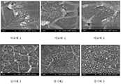
도 1 및도 2는 고분자 전해질에 무기입자가 함유된 나노 복합체 전해질 막의 제조방법 중, 종래 초음파를 이용한 분산 공정 또는 본 발명의 밀링에 의한 분산 공정에 따른 나노 복합체 전해질 막의 파단면(cross section) 및 혼탁도(haziness)를 관찰한 결과이다.1 and2 illustrate a cross section of a nanocomposite electrolyte membrane according to a dispersion process using conventional ultrasonic waves or a dispersion process by milling of the present invention. This is the result of haziness observation.
그 결과, 본 발명의 밀링에 의한 분산 공정으로 제조된 나노 복합체 전해질 막의 경우, 파단면상에 무기입자의 고른 분포를 주사전자현미경 결과로부터 확인하고, 균일하게 분산된 무기입자로부터 빛의 산란을 억제하여, 낮은 혼탁도 즉, 높은 투명도를 확인할 수 있다.As a result, in the case of the nanocomposite electrolyte membrane prepared by the dispersion process by milling of the present invention, the even distribution of inorganic particles on the fracture surface was confirmed from the scanning electron microscope results, and the scattering of light from the uniformly dispersed inorganic particles was suppressed. , Low turbidity, that is, high transparency can be confirmed.
또한, 본 발명의 나노 복합체 전해질 막은 고분자전해질에 균일하게 분산된 무기입자가 효과적으로 물 흡수를 억제하고 이로 인해 부피 변화가 저하된 결과[도 3 및도 4]를 보이고 낮은 메탄올 투과도 성능[도 7]을 확인할 수 있다.In addition, the nanocomposite electrolyte membrane of the present invention has the result that the inorganic particles uniformly dispersed in the polymer electrolyte effectively inhibit the water absorption and thereby the volume change is reduced [FIGS. 3 and4 ] and the low methanol permeability performance [FIG. 7 ] can confirm.
반면에 실온 또는 100℃이상의 고온에서도 0.10 내지 0.13 S/㎝가 유지된 높은 수소이온 전도도를 확인[도 6]함으로써, 본 발명은 연료전지 막으로서의 요구되는 수송 특성 및 막 특성이 개선된 나노 복합체 전해질 막을 제공할 수 있다.On the other hand, by confirming high hydrogen ion conductivity maintained at 0.10 to 0.13 S / cm at room temperature or at a high temperature of 100 ° C. or higher [FIG. 6 ], the present invention provides a nanocomposite electrolyte having improved transport and membrane properties as a fuel cell membrane. May provide a membrane.
이에, 본 발명은 상기 나노 복합체 전해질 막을 고분자전해질 연료전지용 또는 직 접 메탄올 연료전지용 전해질 막에 적용된 막-전극 어셈블리(MEA, membrane-electrode assembly)를 제공한다.Accordingly, the present invention provides a membrane-electrode assembly (MEA) applied to the nanocomposite electrolyte membrane for an electrolyte membrane for a polymer electrolyte fuel cell or a direct methanol fuel cell.
본 발명은 연료전지 막으로서 요구되는 높은 수소이온전도도, 메탄올 크로스오버 등의 수송 특성과 고온에서도 물 흡수율이 낮고, 치수 안정성을 유지하는 등의 막 특성이 우수한 나노 복합체 전해질 막을 연료전지용 막에 적용함으로써, 이를 구비한 막-전극 어셈블리(MEA, membrane-electrode assembly)의 성능을 향상시킬 수 있다.The present invention is applied to a fuel cell membrane by applying a nanocomposite electrolyte membrane having excellent transport properties such as high hydrogen ion conductivity and methanol crossover required as a fuel cell membrane, low membrane water absorption even at high temperature, and excellent dimensional stability such as maintaining dimensional stability. In addition, the performance of a membrane-electrode assembly (MEA) having the same may be improved.
나아가, 이를 구비한 고분자전해질 연료전지 또는 직접 메탄올 연료전지의 성능을 향상시킬 수 있다.Furthermore, the performance of the polymer electrolyte fuel cell or direct methanol fuel cell having the same can be improved.
이하, 실시예를 통하여 본 발명을 보다 상세히 설명하고자 한다.Hereinafter, the present invention will be described in more detail with reference to Examples.
본 실시예는 본 발명을 보다 구체적으로 설명하기 위한 것이며, 본 발명의 범위가 이들 실시예에 한정되는 것은 아니다.This embodiment is intended to illustrate the present invention in more detail, and the scope of the present invention is not limited to these examples.
<실시예 1>≪ Example 1 >
단계 1: 술폰화도 50%의 술폰화 폴리아릴렌에테르술폰 공중합체 제조Step 1: preparation of sulfonated polyarylene ether sulfone copolymer having a sulfonation degree of 50%
100㎖의 가지달린 둥근 플라스크에 가스 주입구, 온도계, 딘-스탁 트랩, 냉각기 및 교반기를 설치하고, 질소 분위기에서 수분동안 공기 및 불순물을 제거한 후, 4,4'-디클로로디페닐술폰 3.4460g, 4,4'-바이페놀(이하 "BP"라고 한다) 3.7242g, 디술폰화디클로로디페닐술폰 3.9301g, K2CO3 3.1787g 및 NMP 44.4㎖, 톨루엔 22.2㎖ (NMP/톨루엔=2/1 V/V)을 투입하고, 80℃ 이상에서 1 시간동안 교반시키면서 단 량체를 용해시켰다.A 100 ml branched round flask was equipped with a gas inlet, thermometer, Dean-Stark trap, cooler and stirrer, removed air and impurities for several minutes in a nitrogen atmosphere, and then 3.4460 g of 4,4'-dichlorodiphenylsulfone. 3.7242 g of 4'-biphenol (hereinafter referred to as "BP"), 3.9301 g of disulfonated dichlorodiphenylsulfone, 3.1787 g of K2CO3 and 44.4 ml of NMP, 22.2 ml of toluene (NMP / toluene = 2/1 V / V) The monomer was dissolved while stirring at 80 ° C. or higher for 1 hour.
이후, 반응용액의 온도를 160℃로 승온시킨 후, 4 시간동안 톨루엔으로 환류 시키면서 반응 생성물인 물을 제거한 다음, 다시 190℃로 승온시켜 딘-스탁 트랩에서 잔류 톨루엔을 완전 제거하고 24 시간동안 반응시켰다. 반응이 종료되면 NMP로 반응용액을 희석시켜 여과한 후, 물에 부어 팽윤된 섬유(swollen fiber) 형태로 침전시키고 여과하였다. 이후, 얻어진 반응 생성물을 120℃의 감압 건조기에서24 시간동안 건조시켜, 술폰화 고분자 공중합체인 술폰화 폴리아릴에테르술폰을 얻었다.Then, after raising the temperature of the reaction solution to 160 ℃, refluxed with toluene for 4 hours to remove the water of the reaction product, and then raised to 190 ℃ to completely remove the residual toluene in the Dean-Stark trap and reaction for 24 hours I was. After the reaction was completed, the reaction solution was diluted with NMP, filtered, poured into water, precipitated in the form of swollen fibers, and filtered. Thereafter, the obtained reaction product was dried in a reduced pressure dryer at 120 ° C. for 24 hours to obtain a sulfonated polyaryl ether sulfone which is a sulfonated polymer copolymer.
단계 2: 나노 복합체 전해질 제조Step 2: Nanocomposite Electrolyte Preparation
상기 제조된 술폰화도(degree of sulfonation) 50%의 수준인 술폰화 폴리아릴렌에테르술폰(SPAES) 공중합체를 40℃에서 디메틸아세트아마이드(DMAc)에 용해시켰다. 이후, 평균 입도가 12nm인 SiO2 무기입자(Aerosil 200)를 SPAES/SiO2 = 97/3 중량비로 혼합하였다. 상기 제조된 용액을 1mm 크기의 비드로 채워진 500㎖ 용기로 이송시킨 후, 배치 형태의 비드 밀링 기기를 이용하여 1시간 동안 분산시켰다. 상기 분산된 용액을 캐스팅 공정을 통해 막을 제조한 이후, 건조 공정을 거쳐 최종 두께가 약 30㎛ 수준의 나노 복합체 전해질 막을 제조하였다.The prepared sulfonated polyarylene ether sulfone (SPAES) copolymer having a degree of sulfonation of 50% was dissolved in dimethylacetamide (DMAc) at 40 ° C. Then, SiO2 inorganic particles (Aerosil 200) having an average particle size of 12 nm were mixed in a SPAES / SiO2 = 97/3 weight ratio. The prepared solution was transferred to a 500 ml container filled with 1 mm beads and dispersed for 1 hour using a bead milling machine in batch form. After the membrane was manufactured by casting the dispersed solution, a nanocomposite electrolyte membrane having a final thickness of about 30 μm was prepared through a drying process.
<실시예 2><Example 2>
상기 실시예 1에서, 술폰화 폴리아릴렌에테르술폰(SPAES)/무기입자(SiO2)간의 혼합비율이 SPAES/SiO2 = 95/5 중량비인 것을 제외하고는, 상기 실시예 1과 동일한 방법으로 수행하여 나노 복합체 전해질 막을 제조하였다.In Example 1, except that the mixing ratio of sulfonated polyarylene ether sulfone (SPAES) / inorganic particles (SiO2 ) is SPAES / SiO2 = 95/5 by weight, in the same manner as in Example 1 It was carried out to prepare a nanocomposite electrolyte membrane.
<실시예 3><Example 3>
상기 실시예 1에서, 술폰화 폴리아릴렌에테르술폰(SPAES)/무기입자(SiO2)간의 혼합비율이 SPAES/SiO2 = 90/10 중량비인 것을 제외하고는, 상기 실시예 1과 동일한 방법으로 수행하여 나노 복합체 전해질 막을 제조하였다.In Example 1, except that the mixing ratio between sulfonated polyarylene ether sulfone (SPAES) / inorganic particles (SiO2 ) is SPAES / SiO2 = 90/10 weight ratio, in the same manner as in Example 1 It was carried out to prepare a nanocomposite electrolyte membrane.
<비교예 1~3><Comparative Example 1-3>
술폰화 폴리아릴렌에테르술폰(SPAES)/무기입자(SiO2)간의 혼합비율을 각각 97/3 중량비, 95/5 중량비 및 90/10 중량비로 수행하되, 상기 실시예 1의 단계 2의 분산공정에서 초음파(sonication)방법을 수행하는 것을 제외하고는 상기 실시예 1과 동일하게 수행하여, 나노 복합체 전해질 막을 제조하였다.The mixing ratio between sulfonated polyarylene ether sulfone (SPAES) / inorganic particles (SiO2 ) was performed at 97/3 weight ratio, 95/5 weight ratio and 90/10 weight ratio, respectively, and the dispersion process of
<비교예 4>≪ Comparative Example 4 &
상기 실시예 1에서, 술폰화 폴리아릴렌에테르술폰(SPAES)/무기입자(SiO2)의 혼합비율이 SPAES/SiO2 = 100/0 중량비인 것을 제외하고는, 상기 실시예 1과 동일한 방법으로 수행하여 나노 복합체 전해질 막을 제조하였다.In Example 1, except that the mixing ratio of sulfonated polyarylene ether sulfone (SPAES) / inorganic particles (SiO2 ) is SPAES / SiO2 = 100/0 weight ratio, in the same manner as in Example 1 It was carried out to prepare a nanocomposite electrolyte membrane.
<비교예 5>≪ Comparative Example 5 &
상용되는 고분자 전해질 막으로서, 나피온(Nafion-115
<실험예 1> 물성 평가 측정Experimental Example 1 Physical Property Evaluation
1. 나노 복합체 전해질 막의 표면관찰1. Surface Observation of Nanocomposite Electrolyte Membranes
도 1은 고분자 전해질막의 제조방법 중, 분산공정에 따라 제조된 나노 복합체 전해질 막의 파단면을 SEM을 이용하여 관찰한 결과로서, 비드 밀링 공정으로 수행된 본 발명의 실시예 1에서 제조된 나노 복합체 전해질 막의 경우, 종래 분산공정인 초음파방법으로 제조된 비교예보다 무기입자 SiO2 입자의 분산성이 향상된 것을 확인하였다.1 is a nanocomposite electrolyte prepared in Example 1 of the present invention performed by the bead milling process as a result of observing the fracture surface of the nanocomposite electrolyte membrane prepared by the dispersion process in the method of manufacturing a polymer electrolyte membrane using a SEM In the case of the film, it was confirmed that the dispersibility of the inorganic particles SiO2 particles improved than the comparative example prepared by the ultrasonic method, which is a conventional dispersion process.
2. 나노 복합체 전해질 막의 혼탁도 측정2. Measurement of Turbidity of Nanocomposite Electrolyte Membranes
상기 실시예 1~3 및 비교예 1~3에서 제조된 나노 복합체 전해질 막의 혼탁도를 측정하고, 그 결과를 하기표 1에 기재하였다.The turbidity of the nanocomposite electrolyte membranes prepared in Examples 1 to 3 and Comparative Examples 1 to 3 was measured, and the results are shown inTable 1 below.
상기 혼탁도(haziness) 결과로부터, 무기입자(SiO2 입자)가 포함되지 않은 술폰화 폴리아릴렌에테르술폰(SPAES) 자체의 막의 경우(비교예 4), 혼탁도가 2%인 것을 기준으로 할 때, 본 발명의 실시예에서 무기입자(SiO2 입자)를 함유한 전해질 막(실시예 1~3)은 동일 무기입자 함량 대비 분산방법을 달리하여 제조된 비교예의 전해질 막(비교예 1~3)보다 전반적으로 낮은 혼탁도 즉, 높은 투명도를 보였다.From the hazeiness result, in the case of the film of sulfonated polyarylene ether sulfone (SPAES) itself containing no inorganic particles (SiO2 particles) (Comparative Example 4), the turbidity should be based on 2%. When the electrolyte membrane (Examples 1 to 3) containing inorganic particles (SiO2 particles) in the embodiment of the present invention, the electrolyte membrane of Comparative Example (Comparative Examples 1 to 3) prepared by varying the dispersion method compared to the same inorganic particle content Overall lower turbidity, ie higher transparency.
이에, 본 발명의 고분자 전해질 막 제조공정은 종래의 분산공정에서 사용되는 밀링 방식으로 수행함으로써, 무기입자의 분산효율을 높여 고분자 전해질에 무기입자가 균일 분산된 나노 복합체 전해질 막이 제조되었음을 확인하였다.Thus, the polymer electrolyte membrane manufacturing process of the present invention was performed by the milling method used in the conventional dispersion process, it was confirmed that the nanocomposite electrolyte membrane in which inorganic particles are uniformly dispersed in the polymer electrolyte by increasing the dispersion efficiency of the inorganic particles.
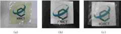
도 2는 고분자 전해질막의 제조방법 중, 분산공정에 따라 제조된 나노 복합체 전해질 막의 혼탁도(haziness)를 비교 관찰한 사진으로서, 무기입자(SiO2 입자)가 포함되지 않은 술폰화 폴리아릴렌에테르술폰(SPAES) 자체가 2%의 혼탁도를 보이는 것을 기준으로 할 때(a), 무기입자(SiO2 입자) 5 중량%를 함유한 실시예 2의 경우(b), 4%로 약간 증가하였다. 반면에, 동일 무기입자를 함유하고 종래의 초음파를 이용한 분산공정으로 제조된 비교예 2의 나노 복합체 전해질 막(c)의 혼탁도는 현저하게 증가하여 투명성이 저하되었다.FIG. 2 is a photograph illustrating a comparison of haziness of nanocomposite electrolyte membranes prepared according to a dispersion process in a method of preparing a polymer electrolyte membrane, wherein sulfonated polyarylene ether sulfone does not include inorganic particles (SiO2 particles). Based on the (SPAES) itself showing a turbidity of 2% (a), for Example 2 containing 5% by weight of inorganic particles (SiO2 particles) (b), it increased slightly to 4%. On the other hand, the turbidity of the nanocomposite electrolyte membrane (c) of Comparative Example 2 containing the same inorganic particles and prepared by a conventional dispersion process using ultrasonic waves was markedly increased, resulting in a decrease in transparency.
3. 물 흡수율 측정3. Water absorption rate measurement
실시예 및 비교예에서 제조된 나노 복합체 전해질 막에 대한 물 흡수율을 측정하기 위하여, 나노 복합체 전해질 막을 탈 이온수로 여러 번 세척하고, 세척된 고분자 전해질 막을 탈 이온수에 24시간 동안 침지시킨 후 꺼내어 표면에 존재하는 물을 제거한 후 무게를 측정하였다(Wwet). 이어서, 동일한 막을 다시 120℃의 감압 건조기에서 24시간동안 건조시킨 후 다시 무게를 측정하였다(Wdry).In order to measure the water absorption rate of the nanocomposite electrolyte membranes prepared in Examples and Comparative Examples, the nanocomposite electrolyte membranes were washed several times with deionized water, and the washed polymer electrolyte membrane was immersed in deionized water for 24 hours and then taken out to the surface. The water present was removed and weighed (Wwet). Subsequently, the same membrane was again dried in a reduced pressure dryer at 120 ° C. for 24 hours and then weighed again (Wdry).
물 흡수율은 하기수학식 1에 의해 산출되었다.The water absorption rate was calculated by the followingequation .

4. 부피 변화율 측정4. Volume change rate measurement
부피 변화율은 물 흡수율 측정방법과 동일하게 수행하되, 무게를 재는 대신에, 부피 변화를 측정한 후, 하기 수학식 2에 의해 산출하였다.Volume change rate was performed in the same manner as the water absorption rate measurement method, but instead of weighing, after measuring the volume change, it was calculated by the followingequation (2 ).

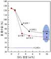
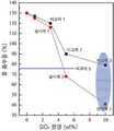
도 3은 고분자 전해질막의 제조방법 중, 분산공정에 따라 제조된 나노 복합체 전해질 막의 물 흡수율 결과이고,도 4는 부피 변화율의 관찰결과이다.3 is a water absorption rate of the nanocomposite electrolyte membrane prepared according to the dispersion process in the method of manufacturing a polymer electrolyte membrane, andFIG. 4 is an observation result of volume change rate.
도 3의 결과로부터, 본 발명의 비드 밀링 분산공정을 통해 제조된 실시예의 나노 복합체 전해질 막은 나피온 전해질 막(비교예 5)보다 높은 물 흡수율(40%)을 보이나, 동일함량의 무기입자 대비 종래의 초음파 분산공정으로 제조된 비교예 1~3의 나노 복합체 전해질 막의 물 흡수율보다 현저히 낮은 물흡수율을 확인하였다.From the results of Figure 3, the nanocomposite electrolyte membrane of the embodiment prepared through the bead milling dispersion process of the present invention shows a higher water absorption rate (40%) than the Nafion electrolyte membrane (Comparative Example 5), but compared to the conventional inorganic particles of the same content The water absorption rate was significantly lower than that of the nanocomposite electrolyte membranes of Comparative Examples 1 to 3 prepared by the ultrasonic dispersion process of.
또한, 부피 변화율 평가에서, 본 발명의 비드 밀링 분산공정을 통해 제조된 실시예의 나노 복합체 전해질 막은 종래의 초음파 분산공정을 통한 경우보다 낮은 면적변화율을 확인하였다.In addition, in the evaluation of the volume change rate, the nanocomposite electrolyte membrane of the example prepared through the bead milling dispersion process of the present invention was confirmed to have a lower area change rate than the case through the conventional ultrasonic dispersion process.
5. 경시안정성 평가5. Assessing Time-lapse Qualification
실시예 및 비교예에서 제조된 나노 복합체 전해질 막을 실온 상에서 물에 스웰링된 막의 부피를 Vs라 하고, 100℃에서 24시간동안 건조한 후의 막의 부피를 Vd로 정의하여 하기수학식 3에 의해 산출하여 막의 경시안정성을 평가하였다.Examples and referred to in Comparative Example A nanocomposite electrolyte membrane Vs The volume of swelling in the water film on the room temperature produced in, and at 100 ℃ for 24 hours to define the volume after film dried to Vd film are calculated by theequation (3) The time stability was evaluated.

상기 결과를도 5에 도시하였는바, 본 발명의 비드 밀링 분산공정을 통해 제조된 실시예의 나노 복합체 전해질 막은 종래의 초음파 분산공정에 의해 제조된 막보다 안정된 경시안정성을 보였으며, 상용 나피온 전해질 막(비교예 5) 대비 동등 또는 그 이상의 안정성을 확인하였다.As shown inFIG. 5 , the nanocomposite electrolyte membrane of the embodiment prepared by the bead milling dispersion process of the present invention showed more stable stability over time than the membrane prepared by the conventional ultrasonic dispersion process, and commercially available Nafion electrolyte membranes. (Comparative Example 5) It was confirmed that the stability of the equivalent or more.
상기 결과로부터, 본 발명의 비드 밀링 분산공정을 통해 제조된 실시예의 나노 복합체 전해질 막은 고분자전해질(SPAES)에 균일하게 분산된 SiO2 입자가 효과적으로 물 흡수를 억제하고 이로 인해 면적 변화가 저하된 것으로 판단할 수 있다. SiO2 입자함량 증가에 따라, 특히 SiO2 입자가 10중량%를 함유할 때, 현저히 낮은 물 흡수율, 낮은 면적 변화율 및 경시안정성을 보였다.From the above results, in the nanocomposite electrolyte membrane of the embodiment prepared through the bead milling dispersion process of the present invention, it was determined that SiO2 particles uniformly dispersed in the polymer electrolyte (SPAES) effectively suppressed water absorption and thereby reduced area change. can do. With increasing SiO2 particle content, especially when the SiO2 particles contained 10% by weight, significantly lower water absorption, lower area change rate, and aging stability were shown.
6. 이온 전도도 측정6. Ionic Conductivity Measurement
실시예 및 비교예에서 제조된 나노 복합체 전해질 막에 대하여, 측정 온도범위 25℃에서 측정 장비[솔라트론사의 Solatron-1280 Impedance/Gain-Phase analyzer]를 이용하여 이온 전도도를 측정하였다. 이때, 임피던스 스펙트럼은 10MHz부터 10Hz까지 기록되었으며, 이온 전도도는 하기수학식 4에 의해 산출되었다.For the nanocomposite electrolyte membranes prepared in Examples and Comparative Examples, ionic conductivity was measured using a measuring instrument (Solatron-1280 Impedance / Gain-Phase analyzer manufactured by Solartron) at a measurement temperature range of 25 ° C. At this time, the impedance spectrum was recorded from 10MHz to 10Hz, the ion conductivity was calculated by the followingequation (4 ).

(상기서, R은 측정 저항(Ω), L은 측정 전극 사이의 길이(cm), A는 제조된 전해질 막의 단면적(㎠)이다.)(Where R is the measurement resistance (Ω), L is the length (cm) between the measurement electrodes, and A is the cross-sectional area (cm 2) of the prepared electrolyte membrane.)
도 6은 고분자 전해질막의 제조방법 중, 분산공정에 따라 제조된 나노 복합체 전해질 막의 수소이온 전도도 측정 결과로서, 실시예 1~3에서 제조된 나노 복합체 전해질 막의 수소이온 전도도가 비교예 1~3보다 높은 값을 보였다.6 is a hydrogen ion conductivity measurement result of the nanocomposite electrolyte membrane prepared according to the dispersion process in the method of manufacturing a polymer electrolyte membrane, the hydrogen ion conductivity of the nanocomposite electrolyte membrane prepared in Examples 1 to 3 is higher than Comparative Examples 1 to 3 Value was shown.
이러한 결과로부터, 고분자전해질(SPAES)에 SiO2 입자가 균일하게 분산됨에 따라, 수소이온의 이동 경로(tortuousity)가 짧아졌기 때문인 것으로 판단된다.From these results, it is believed that as the SiO2 particles are uniformly dispersed in the polymer electrolyte (SPAES), the tortuousity of the hydrogen ions is shortened.
7. 메탄올 투과도 측정7. Methanol Permeability Measurement
메탄올 투과도는 일정한 농도의 메탄올과 물이 담긴 두 셀의 중간에 실시예 및 비교예에서 제조된 나노 복합체 전해질 막을 장착하고, 시간에 따라 투과된 메탄올의 양을 가스크로마토그래피(GC)로 측정하였다. 이때, 메탄올 투과도 측정은 하기수학식 5에 의해 산출되었다.The methanol permeability was measured by mounting a nanocomposite electrolyte membrane prepared in Examples and Comparative Examples in the middle of two cells containing a constant concentration of methanol and water, and the amount of methanol permeated over time was measured by gas chromatography (GC). At this time, the methanol permeability measurement was calculated by the followingequation (5 ).

(상기에서, a는 시간-농도 그래프에서의 기울기이고, VB는 투과된 메탄올의 부피 (㎤), L은 전해질막의 두께(cm), A는 전해질 막의 면적(㎠), CA는 사용된 메탄올의 농도를 나타낸다.)(Where a is the slope in the time-concentration graph, VB is the volume of methanol permeated (cm 3), L is the thickness of the electrolyte membrane (cm), A is the area of the electrolyte membrane (cm 2), and CA is used Shows the concentration of methanol.)
도 7은 고분자 전해질막의 제조방법 중, 분산공정에 따라 제조된 나노 복합체 전해질 막의 메탄올 투과도 측정 결과로서, 실시예에서 제조된 나노 복합체 전해질 막의 메탄올 투과도가 비교예 경우보다 감소한 결과를 보였다. 이러한 결과는 물 흡수율 및 부피 변화율과 일치된 결과로서, 균일하게 분산된 SiO2 입자에 의해 극성 분자인 물 및 메탄올의 흡수가 억제되었음을 확인하였다.FIG. 7 shows methanol permeability measurement results of nanocomposite electrolyte membranes prepared according to a dispersion process in a method of preparing a polymer electrolyte membrane. These results were consistent with the water absorption rate and the volume change rate, and it was confirmed that absorption of water and methanol, which are polar molecules, was inhibited by uniformly dispersed SiO2 particles.
도 1 내지 도 7에서 제시하고 있는바와 같이, 나노 복합체 전해질 막 제조공정에서 동일 조성 및 동일 함량의 무기입자를 함유하더라도, 밀링에 의한 분산공정을 수행하여 제조된 나노 복합체 전해질 막은 별도의 화학적 처리 및 첨가제 없이도, 고분자 전해질에 무기입자를 효과적으로 분산시킬 수 있다.As shown in FIGS. 1 to 7, the nanocomposite electrolyte membrane prepared by performing a dispersion process by milling, even if it contains the same composition and the same amount of inorganic particles in the nanocomposite electrolyte membrane manufacturing process is a separate chemical treatment and Even without additives, the inorganic particles can be effectively dispersed in the polymer electrolyte.
이에, 밀링 공정에 의해 제조된 나노 복합체 전해질 막은 연료전지막으로서의 요구되는 높은 수소이온전도도, 메탄올 크로스오버 등의 수송 특성 및 물 흡수율, 치수 안정성 등의 막 특성에 있어서, 우수한 성능을 보임으로써, 막의 성능 향상, 나아가 이를 구비한 연료전지의 성능을 향상시킬 수 있다.Thus, the nanocomposite electrolyte membrane produced by the milling process exhibits excellent performance in the required high hydrogen ion conductivity as a fuel cell membrane, transport characteristics such as methanol crossover, and membrane characteristics such as water absorption rate and dimensional stability. The performance can be improved, and further, the performance of the fuel cell having the same can be improved.
상기에서 살펴본 바와 같이, 본 발명은As described above, the present invention
첫째, 고분자 전해질에 무기입자가 함유된 나노 복합체 전해질 막의 제조방법에서, 종래 적용되는 교반 또는 초음파 공정이 아닌, 타 분야에서 활용되고 있는 밀링 분 산 기술을 연료전지 분야에 도입하여, 별도의 화학적 처리 및 첨가제 없이도, 고분자 전해질에 나노 크기의 무기입자를 효과적으로 균일 분산시킬 수 있는 나노 복합체 전해질 막의 제조방법을 제공하였다.First, in the method of manufacturing a nanocomposite electrolyte membrane containing inorganic particles in a polymer electrolyte, a milling dispersion technique used in other fields is introduced into the fuel cell field, instead of the stirring or ultrasonic process, which is conventionally applied, to separate chemical treatment. And without an additive, it provides a method for producing a nanocomposite electrolyte membrane that can effectively uniformly disperse nano-sized inorganic particles in a polymer electrolyte.
둘째, 상기 제조방법으로부터, 고분자 전해질 내에 무기입자가 균일 분산되어, 높은 투명도를 가지면서 막 특성이 개선되고 특히, 고온에서 높은 수소이온 전도도를 유지하는 나노 복합체 전해질 막을 제공하였다.Second, from the above production method, the inorganic particles are uniformly dispersed in the polymer electrolyte, thereby providing a nanocomposite electrolyte membrane having high transparency and improving membrane properties, and in particular, maintaining high hydrogen ion conductivity at high temperature.
셋째, 상기 나노 복합체 전해질 막을 고분자전해질 연료전지용 및 직접 메탄올 연료전지용 전해질 막에 적용함으로써, 성능이 향상된 막-전극 어셈블리를 제공하였다.Third, the nanocomposite electrolyte membrane was applied to electrolyte membranes for polymer electrolyte fuel cells and direct methanol fuel cells, thereby providing a membrane-electrode assembly with improved performance.
이상에서 본 발명은 기재된 구체 예에 대해서만 상세히 설명되었지만 본 발명의 기술사상 범위내에서 다양한 변형 및 수정이 가능함은 당업자에게 있어서 명백한 것이며, 이러한 변형 및 수정이 첨부된 특허청구범위에 속함은 당연한 것이다.Although the present invention has been described in detail only with respect to the described embodiments, it will be apparent to those skilled in the art that various modifications and variations are possible within the technical spirit of the present invention, and such modifications and modifications belong to the appended claims.
도 1은 고분자 전해질막의 제조방법 중, 분산공정에 따라 제조된 나노 복합체 전해질 막의 파단면을 관찰한 SEM 사진이고,1 is a SEM photograph observing the fracture surface of the nanocomposite electrolyte membrane prepared according to the dispersion process in the manufacturing method of the polymer electrolyte membrane,
도 2는 고분자 전해질막의 제조방법 중, 분산공정에 따라 제조된 나노 복합체 전해질 막의 혼탁도(haziness) 관찰 사진이고,FIG. 2 is a photograph illustrating a haziness of a nanocomposite electrolyte membrane prepared by a dispersion process in a method of preparing a polymer electrolyte membrane. FIG.
도 3은 고분자 전해질막의 제조방법 중, 분산공정에 따라 제조된 나노 복합체 전해질 막의 물 흡수율 결과이고,3 is a water absorption rate of the nanocomposite electrolyte membrane prepared by the dispersion process in the manufacturing method of the polymer electrolyte membrane,
도 4는 고분자 전해질막의 제조방법 중, 분산공정에 따라 제조된 나노 복합체 전해질 막의 부피 변화율을 나타낸 결과이고,4 is a result showing the volume change rate of the nanocomposite electrolyte membrane prepared by the dispersion process in the manufacturing method of the polymer electrolyte membrane,
도 5는 고분자 전해질막의 제조방법 중, 분산공정에 따라 제조된 나노 복합체 전해질 막의 경시안정성 평가 결과이고,5 is a time-lapse stability evaluation results of the nanocomposite electrolyte membrane prepared by the dispersion process in the manufacturing method of the polymer electrolyte membrane,
도 6은 고분자 전해질막의 제조방법 중, 분산공정에 따라 제조된 나노 복합체 전해질 막의 수소이온 전도도 측정 결과이고,6 is a hydrogen ion conductivity measurement result of the nanocomposite electrolyte membrane prepared according to the dispersion process in the manufacturing method of the polymer electrolyte membrane,
도 7은 고분자 전해질막의 제조방법 중, 분산공정에 따라 제조된 나노 복합체 전해질 막의 메탄올 투과도 측정 결과이다.FIG. 7 is a measurement result of methanol permeability of a nanocomposite electrolyte membrane prepared by a dispersion process in a method of preparing a polymer electrolyte membrane. FIG.
Claims (12)
Translated fromKoreanPriority Applications (1)
| Application Number | Priority Date | Filing Date | Title |
|---|---|---|---|
| KR1020090003602AKR101146191B1 (en) | 2009-01-16 | 2009-01-16 | Method of manufacturing nanocomposite electrolyte, nanocomposite electrolyte manufactured thereby and membrane-electrode assembly |
Applications Claiming Priority (1)
| Application Number | Priority Date | Filing Date | Title |
|---|---|---|---|
| KR1020090003602AKR101146191B1 (en) | 2009-01-16 | 2009-01-16 | Method of manufacturing nanocomposite electrolyte, nanocomposite electrolyte manufactured thereby and membrane-electrode assembly |
Publications (2)
| Publication Number | Publication Date |
|---|---|
| KR20100084237A KR20100084237A (en) | 2010-07-26 |
| KR101146191B1true KR101146191B1 (en) | 2012-05-25 |
Family
ID=42643690
Family Applications (1)
| Application Number | Title | Priority Date | Filing Date |
|---|---|---|---|
| KR1020090003602AExpired - Fee RelatedKR101146191B1 (en) | 2009-01-16 | 2009-01-16 | Method of manufacturing nanocomposite electrolyte, nanocomposite electrolyte manufactured thereby and membrane-electrode assembly |
Country Status (1)
| Country | Link |
|---|---|
| KR (1) | KR101146191B1 (en) |
Cited By (1)
| Publication number | Priority date | Publication date | Assignee | Title |
|---|---|---|---|---|
| US9561579B1 (en) | 2012-12-14 | 2017-02-07 | Samsung Electronics Co., Ltd. | Flexible solid electrolyte, all-solid-state lithium battery including the flexible solid electrolyte, and method of preparing the flexible solid electrolyte |
Families Citing this family (7)
| Publication number | Priority date | Publication date | Assignee | Title |
|---|---|---|---|---|
| WO2016048041A2 (en)* | 2014-09-23 | 2016-03-31 | 주식회사 엘지화학 | Composite membrane containing ion transfer polymer and preparation method therefor |
| CN107004880B (en)* | 2014-12-04 | 2020-07-28 | 株式会社Lg化学 | polymer electrolyte membrane |
| KR101991430B1 (en) | 2014-12-04 | 2019-06-20 | 주식회사 엘지화학 | Halogenated compound, polymer comprising the same and polymer electrolyte membrane using the same |
| JP6447942B2 (en) | 2014-12-04 | 2019-01-09 | エルジー・ケム・リミテッド | Polymer and polymer electrolyte membrane containing the same |
| KR20160067720A (en) | 2014-12-04 | 2016-06-14 | 주식회사 엘지화학 | Polymer and polymer electrolyte membrane using the same |
| CN107710492A (en)* | 2015-06-23 | 2018-02-16 | 株式会社日本触媒 | Conductive material and preparation method thereof and process for purification, and used the nonaqueous electrolytic solution and antistatic additive of the conductive material |
| KR102308461B1 (en) | 2018-05-25 | 2021-10-01 | 주식회사 엘지화학 | Resin composition for preparing of membrane, preparation method for thereof and battery comprising the same |
Citations (4)
| Publication number | Priority date | Publication date | Assignee | Title |
|---|---|---|---|---|
| JP2005183017A (en)* | 2003-12-16 | 2005-07-07 | Konica Minolta Holdings Inc | Proton-conducting electrolyte membrane manufacturing method, proton-conducting electrolyte membrane, and fuel cell using proton-conducting electrolyte membrane |
| KR20050104408A (en)* | 2003-02-28 | 2005-11-02 | 바스프 악티엔게젤샤프트 | Method for producing a polymer system capable of proton exchange, based on polyaryl ether ketones |
| KR20060023674A (en)* | 2004-09-10 | 2006-03-15 | 한국전자통신연구원 | Manufacturing method of phase inversion polymer electrolyte filled with nanoparticles |
| KR20070034388A (en)* | 2005-09-24 | 2007-03-28 | 삼성에스디아이 주식회사 | Nanocomposites, Nanocomposite Electrolyte Membranes and Fuel Cells Using the Same |
- 2009
- 2009-01-16KRKR1020090003602Apatent/KR101146191B1/ennot_activeExpired - Fee Related
Patent Citations (4)
| Publication number | Priority date | Publication date | Assignee | Title |
|---|---|---|---|---|
| KR20050104408A (en)* | 2003-02-28 | 2005-11-02 | 바스프 악티엔게젤샤프트 | Method for producing a polymer system capable of proton exchange, based on polyaryl ether ketones |
| JP2005183017A (en)* | 2003-12-16 | 2005-07-07 | Konica Minolta Holdings Inc | Proton-conducting electrolyte membrane manufacturing method, proton-conducting electrolyte membrane, and fuel cell using proton-conducting electrolyte membrane |
| KR20060023674A (en)* | 2004-09-10 | 2006-03-15 | 한국전자통신연구원 | Manufacturing method of phase inversion polymer electrolyte filled with nanoparticles |
| KR20070034388A (en)* | 2005-09-24 | 2007-03-28 | 삼성에스디아이 주식회사 | Nanocomposites, Nanocomposite Electrolyte Membranes and Fuel Cells Using the Same |
Cited By (1)
| Publication number | Priority date | Publication date | Assignee | Title |
|---|---|---|---|---|
| US9561579B1 (en) | 2012-12-14 | 2017-02-07 | Samsung Electronics Co., Ltd. | Flexible solid electrolyte, all-solid-state lithium battery including the flexible solid electrolyte, and method of preparing the flexible solid electrolyte |
Also Published As
| Publication number | Publication date |
|---|---|
| KR20100084237A (en) | 2010-07-26 |
Similar Documents
| Publication | Publication Date | Title |
|---|---|---|
| KR101146191B1 (en) | Method of manufacturing nanocomposite electrolyte, nanocomposite electrolyte manufactured thereby and membrane-electrode assembly | |
| KR101064986B1 (en) | Ceramic porous support, reinforced composite electrolyte membrane using the same, and membrane-electrode assembly having the same | |
| Martina et al. | Nanosulfonated silica incorporated SPEEK/SPVdF-HFP polymer blend membrane for PEM fuel cell application | |
| JP5109130B2 (en) | Proton conductive hybrid material and catalyst layer for fuel cell using the same | |
| Jothi et al. | An efficient proton conducting electrolyte membrane for high temperature fuel cell in aqueous-free medium | |
| Shen et al. | PVDF-g-PSSA and Al2O3 composite proton exchange membranes | |
| Tsai et al. | Poly (ethylene glycol) modified activated carbon for high performance proton exchange membrane fuel cells | |
| KR100978553B1 (en) | Fluorine-based polymer electrolyte membrane containing a fluorine-based or partially fluorine-based dispersant and a fuel cell comprising the same | |
| JP6150616B2 (en) | Polymer electrolyte composition and polymer electrolyte membrane | |
| KR102447743B1 (en) | Fuctionalized silane based polymer, methods for producing the same and the composite membrane including method as the same | |
| KR20100087061A (en) | Fluorinated polymer electrolyte membrane comprising fully or partially fluorinated surfactant and fuel cell comprising the same | |
| Prashantha et al. | Nanosized TiO2‐filled sulfonated polyethersulfone proton conducting membranes for direct methanol fuel cells | |
| EP2042543A1 (en) | Method for producing polymer electrolyte emulsion | |
| KR101070015B1 (en) | Method for fabricating polymer electrolyte composite membrane and polymer electrolyte fuel cell including polymer electrolyte composite membrane fabricated using the same | |
| KR20110054607A (en) | Reinforced composite electrolyte membrane and preparation method thereof | |
| JP5308894B2 (en) | PROTON CONDUCTIVE COMPOSITE ELECTROLYTE MEMBRANE, MEMBRANE ELECTRODE ASSEMBLY AND FUEL CELL USING THE SAME, AND METHOD FOR PRODUCING THE PROTON CONDUCTIVE COMPOSITE ELECTROLYTE MEMBRANE | |
| Lin et al. | Preparation of Nafion/PTFE/Zr (HPO4) 2 composite membranes by direct impregnation method | |
| CN101338072A (en) | An organic/inorganic composite enhanced non-aqueous proton conductive membrane and its preparation method | |
| JP5328446B2 (en) | Catalyst for fuel cell, method for producing the same, and fuel cell | |
| KR100969982B1 (en) | Electrolyte membrane and membrane electrode assembly for fuel cell, fuel cell | |
| CN101250308A (en) | Medium-temperature proton-conducting membrane material based on silica hollow microspheres and preparation method thereof | |
| Chi et al. | Preparation of poly (vinylidene fluoride) nanocomposite membranes based on graft polymerization and sol–gel process for polymer electrolyte membrane fuel cells | |
| JP2015153573A (en) | Polymer electrolyte membrane, membrane electrode assembly, and solid polymer fuel cell | |
| JP2010138325A (en) | Proton conductive composite electrolyte membrane, and membrane electrode assembly and fuel cell using the same | |
| JP5214212B2 (en) | Proton conductive composite electrolyte membrane, membrane electrode assembly and fuel cell using the same |
Legal Events
| Date | Code | Title | Description |
|---|---|---|---|
| A201 | Request for examination | ||
| PA0109 | Patent application | St.27 status event code:A-0-1-A10-A12-nap-PA0109 | |
| PA0201 | Request for examination | St.27 status event code:A-1-2-D10-D11-exm-PA0201 | |
| P11-X000 | Amendment of application requested | St.27 status event code:A-2-2-P10-P11-nap-X000 | |
| P13-X000 | Application amended | St.27 status event code:A-2-2-P10-P13-nap-X000 | |
| D13-X000 | Search requested | St.27 status event code:A-1-2-D10-D13-srh-X000 | |
| D14-X000 | Search report completed | St.27 status event code:A-1-2-D10-D14-srh-X000 | |
| PG1501 | Laying open of application | St.27 status event code:A-1-1-Q10-Q12-nap-PG1501 | |
| E902 | Notification of reason for refusal | ||
| PE0902 | Notice of grounds for rejection | St.27 status event code:A-1-2-D10-D21-exm-PE0902 | |
| AMND | Amendment | ||
| E13-X000 | Pre-grant limitation requested | St.27 status event code:A-2-3-E10-E13-lim-X000 | |
| P11-X000 | Amendment of application requested | St.27 status event code:A-2-2-P10-P11-nap-X000 | |
| P13-X000 | Application amended | St.27 status event code:A-2-2-P10-P13-nap-X000 | |
| R18-X000 | Changes to party contact information recorded | St.27 status event code:A-3-3-R10-R18-oth-X000 | |
| E601 | Decision to refuse application | ||
| PE0601 | Decision on rejection of patent | St.27 status event code:N-2-6-B10-B15-exm-PE0601 | |
| AMND | Amendment | ||
| E13-X000 | Pre-grant limitation requested | St.27 status event code:A-2-3-E10-E13-lim-X000 | |
| J201 | Request for trial against refusal decision | ||
| P11-X000 | Amendment of application requested | St.27 status event code:A-2-2-P10-P11-nap-X000 | |
| P13-X000 | Application amended | St.27 status event code:A-2-2-P10-P13-nap-X000 | |
| PJ0201 | Trial against decision of rejection | St.27 status event code:A-3-3-V10-V11-apl-PJ0201 | |
| PB0901 | Examination by re-examination before a trial | St.27 status event code:A-6-3-E10-E12-rex-PB0901 | |
| PE0902 | Notice of grounds for rejection | St.27 status event code:A-1-2-D10-D21-exm-PE0902 | |
| E13-X000 | Pre-grant limitation requested | St.27 status event code:A-2-3-E10-E13-lim-X000 | |
| P11-X000 | Amendment of application requested | St.27 status event code:A-2-2-P10-P11-nap-X000 | |
| P13-X000 | Application amended | St.27 status event code:A-2-2-P10-P13-nap-X000 | |
| PN2301 | Change of applicant | St.27 status event code:A-3-3-R10-R13-asn-PN2301 St.27 status event code:A-3-3-R10-R11-asn-PN2301 | |
| R17-X000 | Change to representative recorded | St.27 status event code:A-3-3-R10-R17-oth-X000 | |
| R18-X000 | Changes to party contact information recorded | St.27 status event code:A-3-3-R10-R18-oth-X000 | |
| B701 | Decision to grant | ||
| PB0701 | Decision of registration after re-examination before a trial | St.27 status event code:A-3-4-F10-F13-rex-PB0701 | |
| GRNT | Written decision to grant | ||
| PR0701 | Registration of establishment | St.27 status event code:A-2-4-F10-F11-exm-PR0701 | |
| PR1002 | Payment of registration fee | St.27 status event code:A-2-2-U10-U11-oth-PR1002 Fee payment year number:1 | |
| PG1601 | Publication of registration | St.27 status event code:A-4-4-Q10-Q13-nap-PG1601 | |
| PR1001 | Payment of annual fee | St.27 status event code:A-4-4-U10-U11-oth-PR1001 Fee payment year number:4 | |
| FPAY | Annual fee payment | Payment date:20160324 Year of fee payment:5 | |
| PR1001 | Payment of annual fee | St.27 status event code:A-4-4-U10-U11-oth-PR1001 Fee payment year number:5 | |
| FPAY | Annual fee payment | Payment date:20170329 Year of fee payment:6 | |
| PR1001 | Payment of annual fee | St.27 status event code:A-4-4-U10-U11-oth-PR1001 Fee payment year number:6 | |
| R18-X000 | Changes to party contact information recorded | St.27 status event code:A-5-5-R10-R18-oth-X000 | |
| LAPS | Lapse due to unpaid annual fee | ||
| PC1903 | Unpaid annual fee | St.27 status event code:A-4-4-U10-U13-oth-PC1903 Not in force date:20180509 Payment event data comment text:Termination Category : DEFAULT_OF_REGISTRATION_FEE | |
| PC1903 | Unpaid annual fee | St.27 status event code:N-4-6-H10-H13-oth-PC1903 Ip right cessation event data comment text:Termination Category : DEFAULT_OF_REGISTRATION_FEE Not in force date:20180509 | |
| R18-X000 | Changes to party contact information recorded | St.27 status event code:A-5-5-R10-R18-oth-X000 |