KR101142760B1 - Fixing device of probe card and electronic component testing apparatus - Google Patents
Fixing device of probe card and electronic component testing apparatusDownload PDFInfo
- Publication number
- KR101142760B1 KR101142760B1KR1020097026136AKR20097026136AKR101142760B1KR 101142760 B1KR101142760 B1KR 101142760B1KR 1020097026136 AKR1020097026136 AKR 1020097026136AKR 20097026136 AKR20097026136 AKR 20097026136AKR 101142760 B1KR101142760 B1KR 101142760B1
- Authority
- KR
- South Korea
- Prior art keywords
- probe card
- holder
- restraining means
- main surface
- electronic component
- Prior art date
- Legal status (The legal status is an assumption and is not a legal conclusion. Google has not performed a legal analysis and makes no representation as to the accuracy of the status listed.)
- Expired - Fee Related
Links
Images


Classifications
- G—PHYSICS
- G01—MEASURING; TESTING
- G01R—MEASURING ELECTRIC VARIABLES; MEASURING MAGNETIC VARIABLES
- G01R31/00—Arrangements for testing electric properties; Arrangements for locating electric faults; Arrangements for electrical testing characterised by what is being tested not provided for elsewhere
- G01R31/28—Testing of electronic circuits, e.g. by signal tracer
- G01R31/2851—Testing of integrated circuits [IC]
- G01R31/2886—Features relating to contacting the IC under test, e.g. probe heads; chucks
- G01R31/2889—Interfaces, e.g. between probe and tester
- G—PHYSICS
- G01—MEASURING; TESTING
- G01R—MEASURING ELECTRIC VARIABLES; MEASURING MAGNETIC VARIABLES
- G01R31/00—Arrangements for testing electric properties; Arrangements for locating electric faults; Arrangements for electrical testing characterised by what is being tested not provided for elsewhere
- G01R31/28—Testing of electronic circuits, e.g. by signal tracer
- G01R31/317—Testing of digital circuits
- G01R31/3181—Functional testing
- G01R31/319—Tester hardware, i.e. output processing circuits
- G01R31/31903—Tester hardware, i.e. output processing circuits tester configuration
- G01R31/31905—Interface with the device under test [DUT], e.g. arrangements between the test head and the DUT, mechanical aspects, fixture
- H—ELECTRICITY
- H01—ELECTRIC ELEMENTS
- H01L—SEMICONDUCTOR DEVICES NOT COVERED BY CLASS H10
- H01L22/00—Testing or measuring during manufacture or treatment; Reliability measurements, i.e. testing of parts without further processing to modify the parts as such; Structural arrangements therefor
Landscapes
- Engineering & Computer Science (AREA)
- General Engineering & Computer Science (AREA)
- Physics & Mathematics (AREA)
- General Physics & Mathematics (AREA)
- Computer Hardware Design (AREA)
- Microelectronics & Electronic Packaging (AREA)
- Manufacturing & Machinery (AREA)
- Power Engineering (AREA)
- Testing Or Measuring Of Semiconductors Or The Like (AREA)
- Measuring Leads Or Probes (AREA)
- Tests Of Electronic Circuits (AREA)
Abstract
Translated fromKoreanDescription
Translated fromKorean본 발명은 반도체 웨이퍼에 형성된 집적 회로 소자 등의 각종 전자부품(이하, 대표적으로 IC디바이스라고 칭한다.)의 시험에 사용되는 프로브 카드를 홀더에 고정하는 고정장치에 관한 것이다.BACKGROUND OF THE INVENTION 1. Field of the Invention The present invention relates to a fixing device for fixing a probe card to a holder for use in testing various electronic components (hereinafter, typically referred to as IC devices) formed on semiconductor wafers.
IC디바이스 등의 전자부품의 제조 과정에서는, 반도체 웨이퍼 상에 조립된 상태나 패키징된 상태에서 IC디바이스의 성능이나 기능을 시험하기 위하여 전자부품 시험장치가 이용되고 있다.BACKGROUND OF THE INVENTION In the manufacturing process of an electronic component such as an IC device, an electronic component test apparatus is used to test the performance and function of an IC device in a state of being assembled or packaged on a semiconductor wafer.
피시험 반도체 웨이퍼(W)에 조립된 IC디바이스의 전기적 특성을 시험하는 장치로서 도6에 도시한 바와 같이, 프로버(90)에 의해 웨이퍼(W)를 프로브 카드(50)에 밀착시켜 프로브 카드(50)의 프로브 침(51)을 IC디바이스의 전극에 전기적으로 접촉시킨 상태에서, 프로브 카드(50) 및 테스트 헤드(10)를 통하여 테스터(미도시)에 의해 IC디바이스의 전기적 특성을 시험하는 것이 종래부터 알려져 있다.As an apparatus for testing the electrical characteristics of the IC device assembled to the semiconductor wafer under test W, as shown in FIG. 6, the
프로버(90) 내에는 열원(94)이 설치되어 있고, 상기 열원(94)에 의해 피시험 반도체 웨이퍼(W)를 가열 또는 냉각하여, 반도체 웨이퍼(W)에 소정의 열 스트레스를 인가한 상태에서 IC디바이스의 시험을 실행하고 있다.A
한편, 프로브 카드(50)는 그 외주부에서 나사(55) 등을 이용하여 홀더(70)에 단단하게 고정되어 있다. 그러므로 반도체 웨이퍼(W)의 온도 변화에 따라서 프로브 카드(50)에 열팽창 또는 열수축이 발생하면, 도7A~도7C에 나타낸 바와 같이, 프로브 카드(50)가 수직방향으로 변동하여, 프로브 침(51)의 선단의 높이가 변동한다. 그러므로 피시험 반도체 웨이퍼(W) 상의 전극에 프로브 침(51)을 접촉시킬 때의 침 압력이 변화하여, 고정밀도의 시험을 실시할 수 없는 경우가 있었다.On the other hand, the
본 발명이 해결하고자 하는 과제는, 프로브 침의 선단의 높이의 변동이 적은 프로브 카드의 고정장치를 제공하는 데에 있다.The problem to be solved by the present invention is to provide a fixing device for a probe card with little variation in the height of the tip of the probe needle.
상기 목적을 달성하기 위하여, 본 발명에 따르면, 반도체 웨이퍼에 형성된 피시험 전자부품의 시험에 이용되는 프로브 카드를 홀더에 고정하는 고정장치로서, 상기 프로브 카드의 주면에 실질적으로 평행한 방향에서 상기 프로브 카드가 상기 홀더에 대하여 신축 가능함과 동시에, 상기 프로브 카드의 주면에 대하여 실질적으로 직교하는 방향에서 상기 프로브 카드를 상기 홀더에 구속하고 있는 것을 특징으로 하는 고정장치가 제공된다(청구항 1 참조).In order to achieve the above object, according to the present invention, there is provided a fixing device for fixing a probe card used in a test of an electronic component under test formed on a semiconductor wafer to a holder, the probe in a direction substantially parallel to the main surface of the probe card. A fixing device is provided, characterized in that the card is stretchable with respect to the holder and the probe card is restrained to the holder in a direction substantially perpendicular to the main surface of the probe card (see claim 1).
상기 발명에서는 특별히 한정되지 않지만, 상기 프로브 카드의 주면에 대하여 실질적으로 직교하는 방향에서 상기 프로브 카드를 상기 홀더에 구속하는 구속 수단과, 상기 프로브 카드의 주면에 실질적으로 평행한 방향에서 상기 프로브 카드를 상기 홀더에 대한 상기 프로브 카드의 신축을 허용하는 허용 수단을 구비한 것을 특징으로 하는 것이 바람직하다(청구항 2 참조).Although not specifically limited in the above invention, restraining means for restraining the probe card to the holder in a direction substantially perpendicular to the main surface of the probe card, and the probe card in a direction substantially parallel to the main surface of the probe card. It is preferred to have an allowable means for allowing the expansion and contraction of the probe card relative to the holder (see claim 2).
상기 발명에서는 특별히 한정되지 않지만, 상기 구속 수단은 상기 홀더에 고정되어 있고, 상기 허용 수단은 상기 구속 수단과 상기 프로브 카드의 사이에 설치되어, 상기 평행 방향에서의 상기 구속 수단에 대한 상기 프로브 카드의 신축을 허용하는 제 1의 베어링 부재와, 상기 프로브 카드와 상기 홀더의 사이에 설치되어, 상기 평행방향에서의 상기 홀더에 대한 상기 프로브 카드의 신축을 허용하는 제 2의 베어링 부재를 포함하는 것을 특징으로 하는 것이 바람직하다(청구항 3 참조).Although not specifically limited in the above invention, the restraining means is fixed to the holder, and the allowable means is provided between the restraining means and the probe card, so that the restraining means with respect to the restraining means in the parallel direction. A first bearing member allowing expansion and contraction, and a second bearing member disposed between the probe card and the holder and allowing expansion and contraction of the probe card with respect to the holder in the parallel direction. Preferably (see claim 3).
상기 발명에서는 특별히 한정되지 않지만, 상기 구속 수단은 상기 프로브 카드의 스티프너에 형성된 관통공을 통하여, 상기 홀더에 고정되어 있는 나사 부재를 포함하는 것을 특징으로 하는 것이 바람직하다(청구항 4 참조).Although not specifically limited in the above invention, it is preferable that the restraining means include a screw member fixed to the holder through a through hole formed in the stiffener of the probe card (see claim 4).
상기 발명에서는 특별히 한정되지 않지만, 상기 구속 수단은 상기 프로브 카드에 고정되어 있고, 상기 허용 수단은, 상기 구속 수단과 상기 홀더의 사이에 설치되어, 상기 평행 방향에서의 상기 홀더에 대한 상기 구속 수단의 미소한 이동을 허용하는 제 1의 베어링 부재와, 상기 홀더와 상기 프로브 카드의 사이에 설치되어, 상기 평행 방향에서의 상기 홀더에 대한 상기 프로브 카드의 신축을 허용하는 제 2의 베어링 부재를 포함하는 것을 특징으로 하는 것이 바람직하다(청구항 5 참조).Although it does not specifically limit in the said invention, The said restraining means is being fixed to the said probe card, The said accepting means is provided between the said restraining means and the said holder, and the said restraining means with respect to the said holder in the said parallel direction is carried out. A first bearing member allowing minute movement, and a second bearing member provided between the holder and the probe card, the second bearing member permitting expansion and contraction of the probe card relative to the holder in the parallel direction. It is preferred to be characterized in that (see claim 5).
상기 발명에서는 특별히 한정되지 않지만, 상기 구속 수단은, 상기 홀더에 형성된 관통공을 통하여, 상기 프로브 카드의 스티프너에 고정되어 있는 나사 부재를 포함하는 것을 특징으로 하는 것이 바람직하다(청구항 6 참조).Although it does not specifically limit in the said invention, It is preferable that the said restriction means includes the screw member fixed to the stiffener of the said probe card through the through-hole formed in the said holder (refer Claim 6).
상기 발명에서는 특별히 한정되지 않지만, 상기 프로브 카드 또는 상기 홀더의 한쪽에 상기 프로브 카드의 주면에 실질적으로 평행한 방향을 따라서 설치된 안내 부재와, 상기 홀더 또는 상기 프로브 카드의 다른쪽에 설치되어, 상기 프로브 카드의 주면에 실질적으로 직교하는 방향에서 상기 안내 부재에 결합되어 있는 동시에, 상기 안내 부재 상을 슬라이드 가능한 슬라이드 부재를 구비하고 있는 것을 특징으로 하는 것이 바람직하다(청구항 7 참조).Although not specifically limited in the said invention, The guide card provided in the direction substantially parallel to the main surface of the said probe card in the said probe card or the said holder, and is provided in the other side of the said holder or the said probe card, and the said probe card It is preferable that it is provided with the slide member which is coupled to the said guide member in the direction orthogonal to the main surface of the slide, and is slidable on the said guide member (refer Claim 7).
상기 목적을 달성하기 위하여, 본 발명에 따르면, 반도체 웨이퍼에 형성된 피시험 전자부품의 테스트를 수행하는 시험장치 본체와, 상기 피시험 전자부품과 상기 시험장치 본체의 사이의 전기적인 접속을 확립하는 프로브 카드와, 상기 프로브 카드를 상기 반도체 웨이퍼에 밀착시키는 프로버와, 상기 프로브 카드를 상기 프로버에 고정하는 홀더를 구비한 전자부품 시험장치로서, 상기의 고정장치를 이용하여, 상기 프로브 카드를 상기 홀더에 고정한 것을 특징으로 하는 전자부품 시험장치가 제공된다(청구항 8 참조).In order to achieve the above object, according to the present invention, a probe for establishing an electrical connection between a test apparatus body for performing a test of an electronic component under test formed on a semiconductor wafer, and the electronic component under test and the test apparatus body An electronic component test apparatus comprising a card, a prober for bringing the probe card into close contact with the semiconductor wafer, and a holder for fixing the probe card to the prober, wherein the probe card is used to fix the probe card. An electronic component testing apparatus is provided, which is fixed to a holder (see claim 8).
본 발명에서는 프로브 카드의 열팽창 또는 열수축에 의한 변동량을 수평 방향으로 허용할 수 있기 때문에, 수직방향으로의 변동이 감소하여, 프로브 침의 선단의 높이 변동이 적어진다.In the present invention, since the amount of variation due to thermal expansion or thermal contraction of the probe card can be allowed in the horizontal direction, the variation in the vertical direction is reduced, and the height variation of the tip of the probe needle is reduced.
도1은 본 발명의 제 1실시형태에서의 전자부품 시험장치의 구성을 도시한 개략 단면도.BRIEF DESCRIPTION OF THE DRAWINGS Fig. 1 is a schematic cross-sectional view showing the configuration of an electronic component testing apparatus in a first embodiment of the present invention.
도2는 본 발명의 제 1실시형태에서의 고정장치를 도시한 개략 단면도.Fig. 2 is a schematic sectional view showing the fixing device in the first embodiment of the present invention.
도3은 본 발명의 제 1실시형태에서 프로브 카드가 열팽창된 경우의 고정장치를 도시한 단면도.Fig. 3 is a sectional view showing the fixing device in the case where the probe card is thermally expanded in the first embodiment of the present invention.
도4는 본 발명의 제 2실시형태에서의 고정장치를 도시한 개략 단면도.Fig. 4 is a schematic sectional view showing a fixing device in a second embodiment of the present invention.
도5는 본 발명의 제 3실시형태에서의 고정장치를 도시한 개략 단면도.Fig. 5 is a schematic sectional view showing a fixing device in a third embodiment of the present invention.
도6은 종래의 전자부품 시험장치의 구성을 도시한 개략 단면도.6 is a schematic sectional view showing the structure of a conventional electronic component test apparatus.
도7A는 열팽창에 의한 프로브 카드의 변형을 도시한 도면.Fig. 7A shows the deformation of the probe card due to thermal expansion.
도7B는 열팽창에 의한 프로브 카드의 변형을 도시한 도면.Fig. 7B shows the deformation of the probe card due to thermal expansion.
도7C는 열팽창에 의한 프로브 카드의 변형을 도시한 도면.Fig. 7C shows the deformation of the probe card due to thermal expansion.
부호의 설명Explanation of the sign
10…테스트 헤드10... Test head
50…프로브 카드50... Probe card
51…프로브 침51... Probe needle
54…스티프너54... Stiffener
60A~60C…고정장치60 A to 60 C. Fixture
61…나사61... screw
62…제 1의 베어링 부재62... Primary bearing member
63…제 2의 베어링 부재63... Secondary bearing member
64…나사64... screw
65…제 1의 베이링 부재65... First bearing member
66…제 2의 베어링 부재66... Secondary bearing member
67…리니어 가이드67... Linear guide
70…홀더70... holder
80…어댑터80... adapter
90…프로버90... Fever
W…피시험 반도체 웨이퍼W… Test semiconductor wafer
이하, 본 발명의 실시형태를 도면에 기초하여 설명한다.EMBODIMENT OF THE INVENTION Hereinafter, embodiment of this invention is described based on drawing.
도1은 본 발명의 제 1실시형태에서의 전자부품 시험장치의 구성을 나타낸 개략 단면도, 도2는 본 발명의 제 1실시형태에서의 고정장치를 나타낸 개략 단면도, 도3은 본 발명의 제 1실시형태에서 프로브 카드가 열팽창된 경우의 고정장치를 나타낸 단면도이다.BRIEF DESCRIPTION OF THE DRAWINGS Fig. 1 is a schematic cross sectional view showing the configuration of an electronic component test apparatus in a first embodiment of the present invention, Fig. 2 is a schematic cross sectional view showing a fixing device in a first embodiment of the present invention, and Fig. 3 is a first embodiment of the present invention. It is sectional drawing which shows the fixing device in the case where a probe card is thermally expanded in embodiment.
본 발명의 제 1실시형태에서의 전자부품 시험장치(1)는, 피시험 반도체 웨이퍼(W)에 조립된 IC디바이스의 전기적 특성을 시험하기 위한 장치이다. 상기 전자부품 시험장치(1)는 도1에 나타낸 바와 같이, IC디바이스의 시험을 수행하는 테스터(미도시)에 케이블을 통하여 전기적으로 접속된 테스트 헤드(10)와, 피시험 반도체 웨이퍼(W) 상의 IC디바이스와 테스트 헤드(10)의 사이의 전기적인 접속을 확립하기 위한 프로브 카드(50)와, 피시험 반도체 웨이퍼(W)를 프로브 카드(50)에 밀착시키는 프로버(90)를 구비하고 있다.The electronic component test apparatus 1 according to the first embodiment of the present invention is an apparatus for testing the electrical characteristics of the IC device assembled to the semiconductor wafer W under test. As shown in FIG. 1, the electronic component test apparatus 1 includes a
프로브 카드(50)는 도1에 나타낸 바와 같이, 하이픽스(11)를 통하여 테스트 헤드(10)에 전기적으로 접속되어 있다. 상기 프로브 카드(50)는, 피시험 반도체 웨이퍼(W)에 조립된 IC디바이스의 전극에 전기적으로 접촉하는 다수의 프로브 침(51)과, 상기 프로브 침(51)이 실장된 프린트 기판(52)과, 프로브 카드(50)를 하이픽 스(11)측의 커넥터(12)에 전기적으로 접속하기 위한 다수의 커넥터(53)와, 프로브 카드(50)를 보강하기 위한 스티프너(54)로 구성되어 있다.The
도1에 나타낸 바와 같이, 프로브 침(51)은 프린트 기판(52)의 한쪽의 주면의 대략 중앙 부분에 설치되어 있고, 피시험 반도체 웨이퍼(W)에 조립된 IC디바이스의 전극에 대응하도록 배치되어 있다. 한편, 커넥터(53) 및 스티프너(54)는 프린트 기판(52)의 다른쪽의 주면에 설치되어 있고, 각 프로브 침(51)은 프린트 기판(52) 내에 형성된 배선 패턴을 통하여 커넥터(53)에 전기적으로 접속되어 있다.As shown in Fig. 1, the
상기 프로브 카드(50)는 프로브 침(51)이 중앙 개구(71)를 통하여 아래쪽을 향한 자세로, 환상의 홀더(70)에 홀드되어 있다. 프로브 카드(50)는 그 외주부의 수개소에서, 고정장치(60A)에 의해 홀더(70)에 고정되어 있다.The
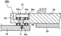
각 고정장치(60A)는 도2에 나타낸 바와 같이, 나사(61) 및 2개의 베어링 부재(62),(63)로 구성되어 있다.Each fixing
나사(61)는, 프로브 카드(50)의 스티프너(54)에 형성된 관통공(54b)을 통하여, 홀더(70)에 형성된 설치공(72)에 나사부(61b)로 고정되어 있다. 나사(61)의 두부(61a)는, 스티프너(54)의 관통공(54b)의 내직경 보다 큰 외직경을 갖고 있기 때문에, 나사(61)를 홀더(70)에 고정함으로써, 나사(61)에 의해 프로브 카드(50)가 홀더(70)에 대하여 연직방향으로 구속되어 있다. 한편, 나사(61)에 대하여 프로브 카드(50)의 수평방향의 신축을 허용하기 위하여, 스티프너(54)의 관통공(54b)은 나사(61)의 나사부(61b)의 직경보다도 약간 크게 형성되어 있다. 또한, 나사(61)의 두부(61a)는 스티프너(54)의 오목부(54a)에 들어가 있다.The
제 1의 베어링 부재(62)는, 환상으로 배치된 복수의 베어링이 수지틀에 회전이 자유롭게 홀드되어 구성되어 있다. 제 1의 베어링 부재(62)의 내측 구멍에 나사(61)의 나사부(61b)가 삽입되어, 제 1의 베어링 부재(62)는 나사(61)의 두부(61a)와 스티프너(54)의 사이에 설치되어 있다. 상기 제 1의 베어링 부재(62)에 의해 수평방향에서의 나사(61)에 대한 프로브 카드(50)의 신축이 허용된다.The
제 2의 베어링 부재(63)도 마찬가지로, 환상으로 배치된 복수의 베어링이 수지틀에 회전이 자유롭게 홀드되어 구성되어 있다. 제 2의 베어링 부재(63)의 내측 구멍에 나사(61)의 나사부(61b)가 삽입되어, 제 2의 베어링 부재(63)는 스티프너(54)와 홀더(70)의 사이에 삽입되어 있다. 상기 제 2의 베어링 부재(63)에 의해 수평방향에서의 홀더(70)에 대한 프로브 카드(50)의 신축이 허용된다.Similarly, the 2nd bearing
도1로 되돌아가서, 이상과 같이 프로브 카드(50)를 홀드하고 있는 홀더(70)는, 환상의 어댑터(80)에 홀드되어 있고, 나아가 상기 어댑터(80)는 프로버(90)의 톱 플레이트(91)에 형성된 개구(92)에 홀드되어 있다. 상기 어댑터(80)는, 피시험 반도체 웨이퍼(W)의 품종, 테스트 헤드(10)의 형상에 대응하여 사이즈가 다른 프로브 카드(50)를 프로버(90)의 개구(92)에 적합하게 하기 위한 것이다. 프로버 카드(50)측과 하이픽스(11)측은, 도1에 나타낸 바와 같이, 하이픽스(11)의 하부에 설치된 훅(13)과, 어딥터(80)에 설치된 훅(81)을 결합시킴으로써 기계적으로 연결되어 있다.Returning to Fig. 1, the
테스트 헤드(10)의 하부에는 하이픽스(11)가 장착되어 있다. 상기 하이픽스(11)의 하면에 커넥터(12)가 설치되어 있다. 상기 커넥터(12)의 일단에는 테스트 헤드(10)에 전기적으로 접속된 동축 케이블이 접속되어 있다. 상기 테스트 헤드(10)측의 커넥터(12)와, 프로브 카드(50)에 설치된 커넥터(53)가 연결됨으로써 테스트 헤드(10)와 프로브 카드(50)가 전기적으로 접속되도록 되어 있다. 커넥터(12),(53)로서, 예컨대 ZIF(Zero Insertion Force) 커넥터 등을 이용할 수 있다.The high fix 11 is attached to the lower part of the
프로버(90)는, 흡착 스테이지에 의해 흡착 파지되어 있는 피시험 반도체 웨이퍼(W)를, XYZ방향으로 이동시키는 동시에, Z축을 중심으로 하여 θ회전시킬 수 있는 반송 아암(93)을 갖고 있다. 또한, 상기 반송 아암(93)의 흡착 스테이지 내에는, 예컨대 히터 등으로 구성되는 열원(94)이 매설되어 있어, 흡착 홀드되어 있는 반도체 웨이퍼(W)를 가열할 수 있게 되어 있다. 한편, IC디바이스의 시험에 즈음하여, 피시험 반도체 웨이퍼(W)를 냉각할 경우에는, 반송 아암(93)의 흡착 스테이지 내에 냉매를 순환시키도록 하여도 좋다.The
시험에 즈음하여, 반송 아암(93)은, 개구(92)를 통하여 프로버(90) 내를 향하고 있는 프로브 카드(50)에 반도체 웨이퍼(W)를 대향시켜, 반도체 웨이퍼(W)를 프로브 카드(50)에 밀착시킨다. 이 상태에서 웨이퍼(W)에 조립된 IC디바이스에 대하여 테스터가 시험 신호를 입출력함으로써, IC디바이스의 시험이 실행된다.On the occasion of the test, the
이 사이에 열원(94)이 피시험 웨이퍼(W)를 가열하고 있으므로, 해당 웨이퍼(W)가 열팽창하는 경우가 있지만, 본 실시형태에서는, 피시험 반도체 웨이퍼(W)가 열팽창하면, 도3에 나타낸 바와 같이, 베어링 부재(62),(63)의 베어링이 회전하여, 제 1의 베어링 부재(62)에 의해 나사(61)에 대한 프로브 카드(50)의 수평방향으로의 확장이 허용되는 동시에, 제 2의 베어링 부재(63)에 의해 홀더(70)에 대한 프로브 카드(50)의 수평방향으로의 확장이 허용되므로, 프로브 카드(50)의 열팽창을 수평방향으로 허용할 수 있다. 그러므로 프로브 카드(50)에서 수직방향으로의 변동이 감소하기 때문에, 프로브 침(51)의 선단의 높이 변동이 적어진다.Since the
한편, 본 발명에 관련된 고정장치는, 상기와 같은 구조에 특별히 한정되지 않는다.In addition, the fixing device which concerns on this invention is not specifically limited to such a structure.
도4는 본 발명의 제2실시형태에서의 고정장치를 나타낸 개략 단면도이다. 본 발명의 제2실시형태에서의 고정장치(60B)는, 도4에 나타낸 바와 같이, 제1실시형태와 마찬가지로, 나사(64) 및 2개의 베어링(65),(66)으로 구성되어 있다. 그렇지만, 나사(64)가 홀더(70)에 형성된 관통공을 통하여, 스티프너(54)에 고정되어 있고, 나사(64)의 두부와 홀더(70)의 사이에 제 1의 베어링(65)이 설치되고, 홀더(70)와 스티프너(54)의 사이에 제 2의 베어링(66)이 설치되어 있는 점에서 제1실시형태와 상위하다.4 is a schematic cross-sectional view showing a fixing device in a second embodiment of the present invention. As shown in Fig. 4, the fixing
본 실시형태에서는, 피시험 반도체 웨이퍼(W)가 열팽창하면, 베어링 부재(65),(66)의 베어링이 회전하여, 제 1의 베어링 부재(65)에 의해, 홀더(70)에 대한 나사(64)의 수평방향으로의 미소한 이동이 허용되는 동시에, 제 2의 베어링 부재(66)에 의해 홀더(70)에 대한 프로브 카드(50)의 수평방향으로의 확장이 허용되므로, 프로브 카드(50)의 열팽창을 수평방향으로 허용할 수 있다. 그러므로 프로브 카드(50)에서 수직방향으로의 변동이 감소하기 때문에, 프로브 침(51)의 선단의 높이 변동이 적어진다.In the present embodiment, when the semiconductor wafer under test W is thermally expanded, the bearings of the bearing
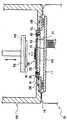
도5는 본 발명의 제3실시형태에서의 고정장치를 나타낸 개략 단면도이다. 본 발명의 제3실시형태에서의 고정장치(60C)는, 도5에 나타낸 바와 같이, 홀더(70)의 상면에 직경방향을 따라서 설치된 가이드 레일(67a)과, 프로브 카드(50)의 하면에 나사(68)에 의해 고정되어, 가이드 레일(67a) 위를 슬라이드 가능한 슬라이드 부재(67b)로 구성되는 리니어 가이드(67)를 갖고 있다. 슬라이드 부재(67b)는, 가이드 레일(67a)의 측면에 형성된 홈에 결합되어 있어, 슬라이드 부재(67b)는 가이드 레일(67a)로부터 연직방향으로 분리되지 않도록 되어 있다.Fig. 5 is a schematic sectional view showing a fixing device in a third embodiment of the present invention. As shown in Fig. 5, the fixing device 60C according to the third embodiment of the present invention has a guide rail 67a provided along the radial direction on the upper surface of the
본 실시형태에서는, 피시험 반도체 웨이퍼(W)가 열팽창하면, 가이드 레일(67a) 위를 슬라이드 부재(67b)가 슬라이드하기 때문에, 프로브 카드(50)의 열팽창을 수평방향으로 허용할 수 있다. 그러므로 프로브 카드(50)에서 수직방향으로의 변동이 감소하기 때문에, 프로브 침(51)의 선단의 높이 변동이 적어진다. 한편, 가이드 레일(67a)을 스티프너(54)의 하면에 고정하고, 슬라이드 부재(67b)를 홀더(70)의 상면에 고정하여도 좋다.In the present embodiment, when the semiconductor wafer under test W is thermally expanded, the
한편, 이상 설명한 실시형태는, 본 발명의 이해를 용이하게 하기 위하여 기재된 것으로서, 본 발명을 한정하기 위하여 기재된 것은 아니다. 따라서, 상기의 실시형태에 개시된 각 요소는, 본 발명의 기술적 범위에 속하는 모든 설계 변경이나 균등물도 포함하는 취지이다.In addition, embodiment described above was described in order to make understanding of this invention easy, and was not described in order to limit this invention. Therefore, each element disclosed in the above embodiment is intended to include all design changes and equivalents belonging to the technical scope of the present invention.
예컨대, 상술한 제1~제3실시형태에서는, 프로브 카드(50)가 열팽창할 경우에 대하여 설명했지만, 냉각에 의해 프로브 카드(50)가 열수축한 경우에도, 고정장치(60A)~(60C)에 의해 그 변동량을 수평방향으로 허용할 수 있다.For example, although the case where the
Claims (8)
Translated fromKoreanApplications Claiming Priority (3)
| Application Number | Priority Date | Filing Date | Title |
|---|---|---|---|
| JP2007145410 | 2007-05-31 | ||
| JPJP-P-2007-145410 | 2007-05-31 | ||
| PCT/JP2008/059457WO2008146705A1 (en) | 2007-05-31 | 2008-05-22 | Fixing device of probe card |
Publications (2)
| Publication Number | Publication Date |
|---|---|
| KR20100017810A KR20100017810A (en) | 2010-02-16 |
| KR101142760B1true KR101142760B1 (en) | 2012-05-08 |
Family
ID=40074958
Family Applications (1)
| Application Number | Title | Priority Date | Filing Date |
|---|---|---|---|
| KR1020097026136AExpired - Fee RelatedKR101142760B1 (en) | 2007-05-31 | 2008-05-22 | Fixing device of probe card and electronic component testing apparatus |
Country Status (6)
| Country | Link |
|---|---|
| US (1) | US8212579B2 (en) |
| JP (1) | JP5306192B2 (en) |
| KR (1) | KR101142760B1 (en) |
| CN (1) | CN101681861A (en) |
| TW (1) | TW200903705A (en) |
| WO (1) | WO2008146705A1 (en) |
Families Citing this family (15)
| Publication number | Priority date | Publication date | Assignee | Title |
|---|---|---|---|---|
| JP5835722B2 (en)* | 2009-12-10 | 2015-12-24 | オルボテック エルティ ソラー,エルエルシー | Automatic ranking multi-directional serial processor |
| JP4873083B2 (en)* | 2010-01-08 | 2012-02-08 | 横河電機株式会社 | Semiconductor test equipment |
| KR101688049B1 (en)* | 2010-12-03 | 2016-12-20 | 삼성전자 주식회사 | Tester and test apparatus comprising the same tester |
| US8736294B2 (en)* | 2010-12-14 | 2014-05-27 | Formfactor, Inc. | Probe card stiffener with decoupling |
| US9134357B1 (en)* | 2011-03-25 | 2015-09-15 | Maxim Integrated, Inc. | Universal direct docking at probe test |
| US9182935B2 (en) | 2011-09-27 | 2015-11-10 | Z124 | Secondary single screen mode activation through menu option |
| ITVI20110343A1 (en)* | 2011-12-30 | 2013-07-01 | St Microelectronics Srl | SYSTEM AND ADAPTER FOR TESTING CHIPS WITH INTEGRATED CIRCUITS IN A PACKAGE |
| JP6054150B2 (en)* | 2012-11-22 | 2016-12-27 | 日本電子材料株式会社 | Probe card case and probe card transport method |
| CN103018496A (en)* | 2012-12-14 | 2013-04-03 | 深圳市天微电子有限公司 | Wafer testing device |
| TWI565951B (en)* | 2015-08-24 | 2017-01-11 | 旺矽科技股份有限公司 | Probe head |
| TWI604198B (en)* | 2016-06-22 | 2017-11-01 | 思達科技股份有限公司 | Testing apparatus, holding assembly, and probe card carrier |
| CN108490925A (en)* | 2018-05-30 | 2018-09-04 | 苏州智华汽车电子有限公司 | Vehicle-mounted camera controller function detects jig |
| JP7129261B2 (en)* | 2018-07-27 | 2022-09-01 | キオクシア株式会社 | test equipment |
| KR102228162B1 (en)* | 2020-06-24 | 2021-03-15 | 오창준 | Probe holder |
| JP7730666B2 (en)* | 2021-06-01 | 2025-08-28 | 株式会社ディスコ | Processing method and processing device |
Citations (4)
| Publication number | Priority date | Publication date | Assignee | Title |
|---|---|---|---|---|
| JP2005328050A (en) | 2004-05-11 | 2005-11-24 | Asml Netherlands Bv | Lithography device and device manufacturing method |
| US7119564B2 (en) | 2001-11-02 | 2006-10-10 | Formfactor, Inc. | Method and system for compensating thermally induced motion of probe cards |
| JP2007057438A (en) | 2005-08-25 | 2007-03-08 | Tokyo Electron Ltd | Probe card |
| US7307435B2 (en) | 2002-08-09 | 2007-12-11 | Nihon Denshizairyo Kabushiki Kaisha | Probe card |
Family Cites Families (3)
| Publication number | Priority date | Publication date | Assignee | Title |
|---|---|---|---|---|
| DE102004023987B4 (en)* | 2004-05-14 | 2008-06-19 | Feinmetall Gmbh | Electrical testing device |
| JP4589710B2 (en)* | 2004-12-13 | 2010-12-01 | 株式会社日本マイクロニクス | Prober |
| JP4486880B2 (en)* | 2004-12-27 | 2010-06-23 | 日本電子材料株式会社 | Contact probe |
- 2008
- 2008-05-22KRKR1020097026136Apatent/KR101142760B1/ennot_activeExpired - Fee Related
- 2008-05-22WOPCT/JP2008/059457patent/WO2008146705A1/enactiveApplication Filing
- 2008-05-22USUS12/598,216patent/US8212579B2/ennot_activeExpired - Fee Related
- 2008-05-22CNCN200880015743Apatent/CN101681861A/enactivePending
- 2008-05-22JPJP2009516278Apatent/JP5306192B2/ennot_activeExpired - Fee Related
- 2008-05-27TWTW097119481Apatent/TW200903705A/ennot_activeIP Right Cessation
Patent Citations (4)
| Publication number | Priority date | Publication date | Assignee | Title |
|---|---|---|---|---|
| US7119564B2 (en) | 2001-11-02 | 2006-10-10 | Formfactor, Inc. | Method and system for compensating thermally induced motion of probe cards |
| US7307435B2 (en) | 2002-08-09 | 2007-12-11 | Nihon Denshizairyo Kabushiki Kaisha | Probe card |
| JP2005328050A (en) | 2004-05-11 | 2005-11-24 | Asml Netherlands Bv | Lithography device and device manufacturing method |
| JP2007057438A (en) | 2005-08-25 | 2007-03-08 | Tokyo Electron Ltd | Probe card |
Also Published As
| Publication number | Publication date |
|---|---|
| JPWO2008146705A1 (en) | 2010-08-19 |
| WO2008146705A1 (en) | 2008-12-04 |
| CN101681861A (en) | 2010-03-24 |
| JP5306192B2 (en) | 2013-10-02 |
| US8212579B2 (en) | 2012-07-03 |
| TW200903705A (en) | 2009-01-16 |
| KR20100017810A (en) | 2010-02-16 |
| TWI373093B (en) | 2012-09-21 |
| US20100127726A1 (en) | 2010-05-27 |
Similar Documents
| Publication | Publication Date | Title |
|---|---|---|
| KR101142760B1 (en) | Fixing device of probe card and electronic component testing apparatus | |
| KR100242531B1 (en) | Probe card assembly and its manufacturing method | |
| JP3388307B2 (en) | Probe card and method for assembling the same | |
| CN104280577B (en) | Electric connecting apparatus | |
| JP6209375B2 (en) | Electrical connection device | |
| KR101164011B1 (en) | Probe card | |
| JPWO2007142204A1 (en) | Probe card | |
| US20100201391A1 (en) | Apparatus and method for testing semiconductor devices | |
| KR19980032057A (en) | Probe card and test device using it | |
| CN1979194B (en) | Electrical testing device and corresponding method for testing electrical samples | |
| KR101104287B1 (en) | Probe card | |
| KR20220056796A (en) | Placement table, testing device, and testing method | |
| KR101569303B1 (en) | Probe card-securing device, probe inspection device, and probe card | |
| JP2012182378A (en) | Positioning mechanism and inspection device of probe card | |
| KR100725838B1 (en) | Probe Cards for Wafer Testing | |
| JP4941169B2 (en) | Probe card mechanism | |
| JP5047322B2 (en) | Probe card and manufacturing method thereof | |
| KR20140110440A (en) | Probing method, probe card for performing the method, and probing apparatus including the probe card | |
| TWI861077B (en) | Portable probe card assembly | |
| CN222233571U (en) | Electrical test head and electrical test circuit board | |
| JPH07318587A (en) | Probe card | |
| KR100357529B1 (en) | Test Apparatus by Batch Type Contact of multiple semiconductor device | |
| KR20250033099A (en) | Semiconductor wafer handling device and semiconductor wafer testing system | |
| KR20120004020A (en) | Probe card |
Legal Events
| Date | Code | Title | Description |
|---|---|---|---|
| A201 | Request for examination | ||
| PA0105 | International application | St.27 status event code:A-0-1-A10-A15-nap-PA0105 | |
| PA0201 | Request for examination | St.27 status event code:A-1-2-D10-D11-exm-PA0201 | |
| PG1501 | Laying open of application | St.27 status event code:A-1-1-Q10-Q12-nap-PG1501 | |
| E902 | Notification of reason for refusal | ||
| PE0902 | Notice of grounds for rejection | St.27 status event code:A-1-2-D10-D21-exm-PE0902 | |
| T11-X000 | Administrative time limit extension requested | St.27 status event code:U-3-3-T10-T11-oth-X000 | |
| T11-X000 | Administrative time limit extension requested | St.27 status event code:U-3-3-T10-T11-oth-X000 | |
| E13-X000 | Pre-grant limitation requested | St.27 status event code:A-2-3-E10-E13-lim-X000 | |
| P11-X000 | Amendment of application requested | St.27 status event code:A-2-2-P10-P11-nap-X000 | |
| P13-X000 | Application amended | St.27 status event code:A-2-2-P10-P13-nap-X000 | |
| E701 | Decision to grant or registration of patent right | ||
| PE0701 | Decision of registration | St.27 status event code:A-1-2-D10-D22-exm-PE0701 | |
| GRNT | Written decision to grant | ||
| PR0701 | Registration of establishment | St.27 status event code:A-2-4-F10-F11-exm-PR0701 | |
| PR1002 | Payment of registration fee | St.27 status event code:A-2-2-U10-U12-oth-PR1002 Fee payment year number:1 | |
| PG1601 | Publication of registration | St.27 status event code:A-4-4-Q10-Q13-nap-PG1601 | |
| PR1001 | Payment of annual fee | St.27 status event code:A-4-4-U10-U11-oth-PR1001 Fee payment year number:4 | |
| FPAY | Annual fee payment | Payment date:20160324 Year of fee payment:5 | |
| PR1001 | Payment of annual fee | St.27 status event code:A-4-4-U10-U11-oth-PR1001 Fee payment year number:5 | |
| FPAY | Annual fee payment | Payment date:20170327 Year of fee payment:6 | |
| PR1001 | Payment of annual fee | St.27 status event code:A-4-4-U10-U11-oth-PR1001 Fee payment year number:6 | |
| FPAY | Annual fee payment | Payment date:20180323 Year of fee payment:7 | |
| PR1001 | Payment of annual fee | St.27 status event code:A-4-4-U10-U11-oth-PR1001 Fee payment year number:7 | |
| R18-X000 | Changes to party contact information recorded | St.27 status event code:A-5-5-R10-R18-oth-X000 | |
| FPAY | Annual fee payment | Payment date:20190326 Year of fee payment:8 | |
| PR1001 | Payment of annual fee | St.27 status event code:A-4-4-U10-U11-oth-PR1001 Fee payment year number:8 | |
| R18-X000 | Changes to party contact information recorded | St.27 status event code:A-5-5-R10-R18-oth-X000 | |
| PR1001 | Payment of annual fee | St.27 status event code:A-4-4-U10-U11-oth-PR1001 Fee payment year number:9 | |
| PR1001 | Payment of annual fee | St.27 status event code:A-4-4-U10-U11-oth-PR1001 Fee payment year number:10 | |
| PC1903 | Unpaid annual fee | St.27 status event code:A-4-4-U10-U13-oth-PC1903 Not in force date:20220428 Payment event data comment text:Termination Category : DEFAULT_OF_REGISTRATION_FEE | |
| PC1903 | Unpaid annual fee | St.27 status event code:N-4-6-H10-H13-oth-PC1903 Ip right cessation event data comment text:Termination Category : DEFAULT_OF_REGISTRATION_FEE Not in force date:20220428 |