KR101138613B1 - Ultrasound system and method for processing color doppler mode image - Google Patents
Ultrasound system and method for processing color doppler mode imageDownload PDFInfo
- Publication number
- KR101138613B1 KR101138613B1KR1020090038474AKR20090038474AKR101138613B1KR 101138613 B1KR101138613 B1KR 101138613B1KR 1020090038474 AKR1020090038474 AKR 1020090038474AKR 20090038474 AKR20090038474 AKR 20090038474AKR 101138613 B1KR101138613 B1KR 101138613B1
- Authority
- KR
- South Korea
- Prior art keywords
- image
- power
- mask
- average value
- speed
- Prior art date
- Legal status (The legal status is an assumption and is not a legal conclusion. Google has not performed a legal analysis and makes no representation as to the accuracy of the status listed.)
- Active
Links
Images


Classifications
- G—PHYSICS
- G01—MEASURING; TESTING
- G01S—RADIO DIRECTION-FINDING; RADIO NAVIGATION; DETERMINING DISTANCE OR VELOCITY BY USE OF RADIO WAVES; LOCATING OR PRESENCE-DETECTING BY USE OF THE REFLECTION OR RERADIATION OF RADIO WAVES; ANALOGOUS ARRANGEMENTS USING OTHER WAVES
- G01S15/00—Systems using the reflection or reradiation of acoustic waves, e.g. sonar systems
- G01S15/88—Sonar systems specially adapted for specific applications
- G01S15/89—Sonar systems specially adapted for specific applications for mapping or imaging
- G01S15/8906—Short-range imaging systems; Acoustic microscope systems using pulse-echo techniques
- G01S15/8979—Combined Doppler and pulse-echo imaging systems
- A—HUMAN NECESSITIES
- A61—MEDICAL OR VETERINARY SCIENCE; HYGIENE
- A61B—DIAGNOSIS; SURGERY; IDENTIFICATION
- A61B8/00—Diagnosis using ultrasonic, sonic or infrasonic waves
- A61B8/13—Tomography
- A61B8/14—Echo-tomography
- G—PHYSICS
- G01—MEASURING; TESTING
- G01S—RADIO DIRECTION-FINDING; RADIO NAVIGATION; DETERMINING DISTANCE OR VELOCITY BY USE OF RADIO WAVES; LOCATING OR PRESENCE-DETECTING BY USE OF THE REFLECTION OR RERADIATION OF RADIO WAVES; ANALOGOUS ARRANGEMENTS USING OTHER WAVES
- G01S7/00—Details of systems according to groups G01S13/00, G01S15/00, G01S17/00
- G01S7/52—Details of systems according to groups G01S13/00, G01S15/00, G01S17/00 of systems according to group G01S15/00
- G01S7/52017—Details of systems according to groups G01S13/00, G01S15/00, G01S17/00 of systems according to group G01S15/00 particularly adapted to short-range imaging
- G01S7/52053—Display arrangements
- G01S7/52057—Cathode ray tube displays
- G01S7/5206—Two-dimensional coordinated display of distance and direction; B-scan display
- G—PHYSICS
- G06—COMPUTING OR CALCULATING; COUNTING
- G06T—IMAGE DATA PROCESSING OR GENERATION, IN GENERAL
- G06T7/00—Image analysis
- G06T7/10—Segmentation; Edge detection
- G06T7/11—Region-based segmentation
- G—PHYSICS
- G06—COMPUTING OR CALCULATING; COUNTING
- G06T—IMAGE DATA PROCESSING OR GENERATION, IN GENERAL
- G06T7/00—Image analysis
- G06T7/10—Segmentation; Edge detection
- G06T7/136—Segmentation; Edge detection involving thresholding
- A—HUMAN NECESSITIES
- A61—MEDICAL OR VETERINARY SCIENCE; HYGIENE
- A61B—DIAGNOSIS; SURGERY; IDENTIFICATION
- A61B8/00—Diagnosis using ultrasonic, sonic or infrasonic waves
- A61B8/08—Clinical applications
- A—HUMAN NECESSITIES
- A61—MEDICAL OR VETERINARY SCIENCE; HYGIENE
- A61B—DIAGNOSIS; SURGERY; IDENTIFICATION
- A61B8/00—Diagnosis using ultrasonic, sonic or infrasonic waves
- A61B8/48—Diagnostic techniques
- A61B8/488—Diagnostic techniques involving Doppler signals
- G—PHYSICS
- G01—MEASURING; TESTING
- G01S—RADIO DIRECTION-FINDING; RADIO NAVIGATION; DETERMINING DISTANCE OR VELOCITY BY USE OF RADIO WAVES; LOCATING OR PRESENCE-DETECTING BY USE OF THE REFLECTION OR RERADIATION OF RADIO WAVES; ANALOGOUS ARRANGEMENTS USING OTHER WAVES
- G01S7/00—Details of systems according to groups G01S13/00, G01S15/00, G01S17/00
- G01S7/52—Details of systems according to groups G01S13/00, G01S15/00, G01S17/00 of systems according to group G01S15/00
- G01S7/52017—Details of systems according to groups G01S13/00, G01S15/00, G01S17/00 of systems according to group G01S15/00 particularly adapted to short-range imaging
- G01S7/52077—Details of systems according to groups G01S13/00, G01S15/00, G01S17/00 of systems according to group G01S15/00 particularly adapted to short-range imaging with means for elimination of unwanted signals, e.g. noise or interference
- G—PHYSICS
- G06—COMPUTING OR CALCULATING; COUNTING
- G06T—IMAGE DATA PROCESSING OR GENERATION, IN GENERAL
- G06T2207/00—Indexing scheme for image analysis or image enhancement
- G06T2207/10—Image acquisition modality
- G06T2207/10132—Ultrasound image
Landscapes
- Engineering & Computer Science (AREA)
- Physics & Mathematics (AREA)
- Radar, Positioning & Navigation (AREA)
- Remote Sensing (AREA)
- General Physics & Mathematics (AREA)
- Acoustics & Sound (AREA)
- Computer Networks & Wireless Communication (AREA)
- Computer Vision & Pattern Recognition (AREA)
- Theoretical Computer Science (AREA)
- Health & Medical Sciences (AREA)
- Life Sciences & Earth Sciences (AREA)
- Nuclear Medicine, Radiotherapy & Molecular Imaging (AREA)
- Molecular Biology (AREA)
- Pathology (AREA)
- Radiology & Medical Imaging (AREA)
- Biomedical Technology (AREA)
- Heart & Thoracic Surgery (AREA)
- Medical Informatics (AREA)
- Biophysics (AREA)
- Surgery (AREA)
- Animal Behavior & Ethology (AREA)
- General Health & Medical Sciences (AREA)
- Public Health (AREA)
- Veterinary Medicine (AREA)
- Ultra Sonic Daignosis Equipment (AREA)
Abstract
Translated fromKoreanDescription
Translated fromKorean본 발명은 초음파 시스템에 관한 것으로, 특히 컬러 도플러 모드 영상을 처리하는 초음파 시스템 및 방법에 관한 것이다.TECHNICAL FIELD The present invention relates to ultrasound systems, and more particularly, to ultrasound systems and methods for processing color Doppler mode images.
초음파 시스템은 무침습 및 비파괴 특성을 가지고 있어, 대상체 내부의 정보를 얻기 위한 의료 분야에서 널리 이용되고 있다. 초음파 시스템은 대상체를 직접 절개하여 관찰하는 외과 수술의 필요 없이, 대상체 내부의 고해상도 영상을 실시간으로 의사에게 제공할 수 있으므로 의료 분야에서 매우 중요하게 사용되고 있다.Ultrasound systems have non-invasive and non-destructive properties and are widely used in the medical field for obtaining information inside an object. Ultrasound systems are very important in the medical field because they can provide a doctor with a high-resolution image of the inside of a subject in real time, without the need for a surgical operation to directly incise and observe the subject.
일반적으로, 초음파 시스템은 도플러 효과(Doppler effect)를 이용하여 움직이고 있는 대상체와 산란체의 속도를 표시하는 컬러 도플러 모드(color doppler mode) 영상을 제공한다. 컬러 도플러 모드 영상은 도플러 신호의 파워를 2차원 분포로 나타내는 파워 영상 및 도플러 신호의 속도를 2차원 분포로 나타내는 속도 영상을 포함한다. 컬러 도플러 모드 영상은 실시간으로 혈류를 시각화할 수 있을 뿐만 아니라, 큰 혈관에서의 높은 속도의 혈류에서부터 작은 혈관에서의 낮은 속도의 혈류까지 광범위한 혈류의 상태를 표현할 수 있다.In general, the ultrasound system provides a color doppler mode image indicating the speed of a moving object and a scatterer using a Doppler effect. The color Doppler mode image includes a power image representing power of the Doppler signal in a two-dimensional distribution and a velocity image representing speed of the Doppler signal in a two-dimensional distribution. In addition to visualizing blood flow in real time, color Doppler mode images can represent a wide range of blood flow conditions, from high velocity blood flow in large vessels to low velocity blood flow in small vessels.
종래에는 속도 영상에 대해 평활화 처리만을 수행하였다. 이로 인해 혈류가 흐르는 혈관 영역이 확대되어, 속도 영상에서 실제 혈관 영역이 넘치게 보이는 현상(블러딩(bleeding))이 발생하고, 가는 혈관이 주변과 블러딩되어 보이지 않게 되는 현상(가는 혈관 소실)이 발생하고, 속도 영상에서 혈관의 일부가 끊어지는 현상(연결성 손실)이 발행하며, 속도 영상에서 임상적 의미가 있는 혈류의 피크가 없어지는 현상(피크 소실)이 발생하는 문제점이 있다.Conventionally, only the smoothing process is performed on speed images. As a result, the blood vessel region in which the blood flow flows is enlarged, and a phenomenon in which the actual vessel region is overflowed (bleeding) in the velocity image occurs, and a phenomenon in which thin blood vessels are blurred with the surroundings (thin vessel loss) And a phenomenon in which part of blood vessels are broken (loss of connectivity) in the velocity image, and a phenomenon in which a peak of blood flow that is clinically meaningful disappears in the velocity image (peak loss).
한편, 파워 영상은 고정 임계(fixed thresholding) 방법을 사용하여 파워 영상의 화소에 대해 유효성을 판단하고 있다. 그러나, 혈류는 심장 박동에 따라 파워가 변하게 되며, 경우에 따라 파워가 작은 경우 파워 영상에서 표시되는 혈관 영역이 매우 작아지는 현상(혈관 영역 축소)이 발생하는 문제점이 있다.Meanwhile, the power image determines the validity of the pixels of the power image by using a fixed thresholding method. However, the blood flow has a problem in that the power changes according to the heart rate, and in some cases, when the power is small, a phenomenon in which the blood vessel region displayed in the power image becomes very small (vascular region reduction) occurs.
본 발명은 파워 영상 및 속도 영상 중 어느 하나를 이용하여 관심영역(예를 들어, 혈관 영역)을 검출하기 위한 마스크를 형성하고, 형성된 마스크를 이용하여 파워 영상 및 속도 영상을 보다 정확하게 처리하는 초음파 시스템 및 방법을 제공한다.The present invention forms a mask for detecting a region of interest (for example, a blood vessel region) using any one of a power image and a velocity image, and uses the formed mask to more accurately process the power image and the velocity image. And methods.
본 발명에 따른 초음파 시스템은, 초음파 신호를 대상체에 송신하고 대상체로부터 반사되는 초음파 에코신호를 수신하여 도플러 신호를 연속적으로 획득하도록 동작하는 신호 획득부; 및 상기 도플러 신호를 이용하여 컬러 도플러 모드 영상 - 상기 컬러 도플러 모드 영상은 파워 영상 및 속도 영상을 포함함 -을 형성하고, 상기 컬러 도플러 모드 영상을 이용하여 관심영역을 검출하기 위한 마스크를 형성하고, 상기 마스크를 이용하여 상기 파워 영상 및 상기 속도 영상에 마스킹 처리를 수행하도록 동작하는 프로세서를 포함한다.According to an aspect of the present invention, there is provided an ultrasound system, including: a signal obtaining unit configured to transmit an ultrasound signal to an object, and receive an ultrasound echo signal reflected from the object to continuously obtain a Doppler signal; And forming a color Doppler mode image using the Doppler signal, wherein the color Doppler mode image includes a power image and a velocity image, and forming a mask for detecting a region of interest using the color Doppler mode image. And a processor operative to perform masking processing on the power image and the speed image using the mask.
또한, 본 발명에 따른, 신호 획득부 및 프로세서를 포함하는 초음파 시스템의 컬러 도플러 모드 영상 처리 방법은, a) 상기 신호 획득부에서, 초음파 신호를 대상체에 송신하고 대상체로부터 반사되는 초음파 에코신호를 수신하여 도플러 신호를 연속적으로 획득하는 단계; b) 상기 프로세서에서, 상기 도플러 신호를 이용하여 컬러 도플러 모드 영상 - 상기 컬러 도플러 모드 영상은 파워 영상 및 속도 영상을 포함함 -을 형성하는 단계; c) 상기 프로세서에서, 상기 컬러 도플러 모드 영상을 이용하여 관심영역을 검출하기 위한 마스크를 형성하는 단계; 및 d) 상기 프로세서에서, 상기 마스크를 이용하여 상기 파워 영상 및 상기 속도 영상에 마스킹 처리를 수행하는 단계를 포함한다.In addition, according to the present invention, a color Doppler mode image processing method of an ultrasound system including a signal acquisition unit and a processor, a) in the signal acquisition unit, transmits an ultrasonic signal to the object and receives the ultrasonic echo signal reflected from the object Continuously acquiring a Doppler signal; b) at the processor, forming a color Doppler mode image using the Doppler signal, wherein the color Doppler mode image includes a power image and a velocity image; c) in the processor, forming a mask for detecting a region of interest using the color Doppler mode image; And d) in the processor, masking the power image and the speed image using the mask.
본 발명에 의하면, 마스크를 이용하여 블러딩, 가는 혈관 소실, 연결성 손실, 피크 손실 및 혈관 축소 없이 파워 영상 및 속도 영상을 정확하게 처리할 수 있다.According to the present invention, a mask can be used to accurately process power images and velocity images without blurring, thin blood vessel loss, loss of connectivity, peak loss, and vessel reduction.
이하, 첨부된 도면을 참조하여 본 발명의 실시예를 설명한다.Hereinafter, with reference to the accompanying drawings will be described an embodiment of the present invention.
도 1은 본 발명의 실시예에 따른 초음파 시스템(100)의 구성을 보이는 블록 도이다. 초음파 시스템(100)은 신호 획득부(110), 프로세서(120), 디스플레이부(130) 및 제어부(140)를 포함한다.1 is a block diagram showing the configuration of an
신호 획득부(110)는 초음파 신호를 대상체에 송신하고 대상체로부터 반사되는 초음파 신호(즉, 초음파 에코신호)를 수신하여, 프레임에 해당하는 도플러 신호를 연속적으로 획득한다. 여기서, 프레임은 컬러 도플러 모드(color doppler mode) 영상의 프레임을 포함한다.The signal acquirer 110 transmits an ultrasound signal to the object, receives an ultrasound signal reflected from the object (that is, an ultrasound echo signal), and continuously obtains a Doppler signal corresponding to a frame. Here, the frame includes a frame of a color doppler mode image.
도 2는 본 발명의 실시예에 따른 신호 획득부(110)의 구성을 보이는 블록도이다. 신호 획득부(110)는 송신신호 형성부(111), 복수의 변환소자(transducer element)(도시하지 않음)를 포함하는 초음파 프로브(112), 빔 포머(113) 및 도플러 신호 형성부(114)를 포함한다.2 is a block diagram showing the configuration of the
송신신호 형성부(111)는 변환소자의 위치 및 집속점을 고려하여, 복수의 변환소자 각각에 인가될 송신신호를 연속적으로 형성한다. 본 실시예에서 송신신호는 프레임을 얻기 위한 송신신호를 포함한다.The transmission
초음파 프로브(112)는 송신신호 형성부(111)로부터 송신신호가 제공되면, 송신신호를 초음파 신호로 변환한다. 초음파 프로브(112)는 초음파 신호를 대상체에 송신하고 대상체로부터 반사되는 초음파 에코신호를 수신하여 수신신호를 형성한다.When the transmission signal is provided from the transmission
빔 포머(113)는 초음파 프로브(112)로부터 수신신호가 제공되면, 수신신호를 아날로그 디지털 변환하여 디지털 신호를 형성한다. 빔 포머(113)는 변환소자의 위치 및 집속점을 고려하여 디지털 신호를 수신집속시켜 수신집속신호를 형성한다.When the received signal is provided from the
도플러 신호 형성부(114)는 빔 포머(113)로부터 수신집속신호가 제공되면, 수신집속신호를 이용하여 도플러 신호를 형성한다. 도플러 신호는 파워 정보 및 속도 정보를 포함한다. 아울러, 도플러 신호 형성부(114)는 도플러 신호를 형성하는데 필요한 다양한 신호 처리(예를 들어, 게인(gain) 조절, 필터링 처리 등)를 수신집속신호에 수행할 수도 있다.When the reception focused signal is provided from the
다시 도 1을 참조하면, 프로세서(120)는 신호 획득부(110)로부터 제공되는 도플러 신호를 이용하여 컬러 도플러 모드 영상을 형성하고, 컬러 도플러 모드 영상을 이용하여 혈관 영역을 검출하기 위한 마스크를 형성하며, 마스크를 이용하여 컬러 도플러 모드 영상에 마스킹 처리를 수행한다. 컬러 도플러 모드 영상은 도플러 신호의 파워를 2차원 분포로 나타내는 파워 영상 및 도플러 신호의 속도를 2차원 분포로 나타내는 속도 영상을 포함한다.Referring back to FIG. 1, the
도 3은 본 발명의 실시예에 따른 프로세서(120)의 구성을 보이는 블록도이다. 프로세서(120)는 영상 형성부(121), 마스크 형성부(122), 제1 영상 처리부(123) 및 제2 영상 처리부(124)를 포함한다.3 is a block diagram showing the configuration of a
영상 형성부(121)는 신호 획득부(110)로부터 도플러 신호가 제공되면, 도플러 신호를 이용하여 파워 영상 및 속도 영상을 형성한다.When the Doppler signal is provided from the
마스크 형성부(122)는 영상 형성부(121)로부터 제공되는 파워 영상을 이용하여 관심영역인 혈관 영역을 검출하기 위한 마스크를 형성한다. 본 실시예에서 마스크 형성부(122)는 파워 영상 처리부(122a), 마스크 설정부(122b), 마스크 처리부(122c) 및 플래쉬 잡음 제거부(122d)를 포함한다.The
파워 영상 처리부(122a)는 영상 형성부(121)로부터 순차적으로 제공되는 파워 영상을 분석하여, 파워 평균값이 임계값 이상인 파워 영상을 기준 파워 영상으로 설정한다. 아울러, 파워 영상 처리부(122a)는 파워 평균값이 임계값 미만인 파워 영상을 기준 파워 영상과 합성하여 합성 영상을 형성한다.The
도 4를 참조하여, 파워 영상 처리부(122a)가 영상 형성부(121)로부터 순차적으로 제공되는 파워 영상을 이용하여 기준 파워 영상을 설정하고 합성 영상을 형성하는 예를 설명한다.Referring to FIG. 4, an example in which the
파워 영상 처리부(122a)는 영상 형성부(121)로부터 첫번째 파워 영상(이하, 제1 파워 영상이라 함)(PI1)이 제공되면, 제1 파워 영상(PI1)의 파워 평균값(이하, 제1 파워 평균값이라 함)을 산출하고, 제1 파워 평균값을 기준 파워 평균값으로 설정한다. 파워 영상 처리부(122a)는 제1 파워 영상(PI1)을 기준 파워 영상으로 설정하여 출력한다.When the first power image (hereinafter, referred to as a first power image) PI1 is provided from the
파워 영상 처리부(122a)는 영상 형성부(121)로부터 두번째 파워 영상(이하, 제2 파워 영상이라 함)(PI2)이 제공되면, 제2 파워 영상(PI2)의 파워 평균값(이하, 제2 파워 평균값이라 함)을 산출한다. 파워 영상 처리부(122a)는 제2 파워 평균값과 임계값(예를 들어, 기준 파워 평균값×0.8)을 비교하여 제2 파워 평균값이 임계값 이상인 것으로 판단되면, 제2 파워 평균값을 기준 파워 평균값으로 설정한다. 파워 영상 처리부(122a)는 제2 파워 영상(PI2)을 기준 파워 영상으로 설정한다.When the second power image (hereinafter, referred to as a second power image) PI2 is provided from the
파워 영상 처리부(122a)는 영상 형성부(121)로부터 세번째 파워 영상(이하, 제3 파워 영상이라 함)(PI3)이 제공되면, 제3 파워 영상(PI3)의 파워 평균값(이하, 제3 파워 평균값이라 함)을 산출한다. 파워 영상 처리부(122a)는 제3 파워 평균값과 임계값(기준 파워 평균값×0.8)을 비교하여 제3 파워 평균값이 임계값 이상인 것으로 판단되면, 제3 파워 평균값을 기준 파워 평균값으로 설정한다. 파워 영상 처리부(122a)는 제3 파워 영상(PI3)을 기준 파워 영상으로 설정한다.When the third power image (hereinafter referred to as a third power image) PI3 is provided from the
파워 영상 처리부(122a)는 영상 형성부(121)로부터 네번째 파워 영상(이하, 제4 파워 영상이라 함)(PI4)이 제공되면, 제4 파워 영상(PI4)의 파워 평균값(이하, 제4 파워 평균값이라 함)을 산출한다. 파워 영상 처리부(122a)는 제4 파워 평균값과 임계값(기준 파워 평균값×0.8)을 비교하여 제2 파워 평균값이 임계값 미만인 것으로 판단되면, 제4 파워 영상(PI4)과 기준 파워 영상(PI3)을 합성하여 합성영상(CI4)을 형성한다. 여기서, 기준 파워 영상과 파워 영상을 합성하는 것은 파워 영상의 파워가 작아 파워 영상에서 표시되는 혈관 영역이 매우 작아지는 것을 방지하기 위함이다.When the power
파워 영상 처리부(122a)는 영상 형성부(121)로부터 다섯번째 파워 영상(이하, 제5 파워 영상이라 함)(PI5) 내지 여덟번째 파워 영상(이하, 제8 파워 영상이라 함)(PI8)이 제공되면, 제5 내지 제8 파워 영상(PI5 내지 PI8) 각각의 파워 평균값(이하, 제5 내지 제8 파워 평균값이라 함)을 산출한다. 파워 영상 처리부(122a)는 제5 내지 제8 파워 평균값과 임계값(기준 파워 평균값×0.8)을 비교하여 제5 내지 제8 파워 평균값이 임계값 미만인 것으로 판단되면, 제5 내지 제8 파워 영상(PI5 내지 PI8) 각각과 기준 파워 영상(PI3)을 합성하여 합성영상(CI5 내지 CI8)을 형성한다.The
파워 영상 처리부(122a)는 영상 형성부(121)로부터 아홉번째 파워 영상(이하, 제9 파워 영상이라 함)(PI9)이 제공되면, 제9 파워 영상(PI9)의 파워 평균값(이하, 제9 파워 평균값이라 함)을 산출한다. 파워 영상 처리부(122a)는 제9 파워 평균값과 임계값(기준 파워 평균값×0.8)을 비교하여 제9 파워 평균값이 임계값 이상인 것으로 판단되면, 제9 파워 평균값을 기준 파워 평균값으로 설정한다. 파워 영상 처리부(122a)는 제9 파워 영상(PI9)을 기준 파워 영상으로 설정하여 출력한다.When the ninth power image (hereinafter, referred to as a ninth power image) PI9 is provided from the
파워 영상 처리부(122a)는 영상 형성부(121)로부터 열번째 파워 영상(이하, 제10 파워 영상이라 함)(PI10) 내지 열두번째 파워 영상(이하, 제12 파워 영상이라 함)(PI12)이 제공되면, 제10 내지 제12 파워 영상(PI10 내지 PI12) 각각의 파워 평균값(이하, 제10 내지 제12 파워 평균값이라 함)을 산출한다. 파워 영상 처리부(122a)는 제10 내지 제12 파워 평균값과 임계값(기준 파워 평균값×0.8)을 비교하여 제10 내지 제12 파워 평균값이 임계값 미만인 것으로 판단되면, 제10 내지 제12 파워 영상(PI10 내지 PI12) 각각과 기준 파워 영상(PI9)을 합성하여 합성영상(CI10 내지 CI12)을 형성한다.The power
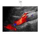
다시 도 3을 참조하면, 마스크 설정부(122b)는 파워 영상 처리부(122a)로부 터 제공되는 기준 파워 영상(PI1 내지 PI3, PI9) 및 합성영상(CI4 내지 CI8, CI10 내지 CI12) 각각을 이용하여 도 5a에 도시된 바와 같이 관심영역, 즉 혈관 영역을 검출하기 위한 마스크(210)를 설정한다. 마스크는 공지된 다양한 방법을 통해 설정될 수 있다. 일례로서, 마스크는 임계값에 의한 방법, 영역 확장 방법, 영역 분할 방법, 외곽선 추출에 의한 방법, 그래프를 이용한 방법, 워터쉐드(watershed) 방법 등을 통해 설정될 수 있다.Referring back to FIG. 3, the
마스크 처리부(122c)는 도 5b에 도시된 바와 같이 마스크 설정부(122b)에서 설정된 마스크의 외곽을 검출한다. 외곽은 공지된 다양한 방법을 통해 검출될 수 있다. 일례로서, 외곽은 외곽선 추출(contour following), 형태학적 처리(mathematical morphological operation) 등을 통해 검출될 수 있다. 마스크 처리부(122c)는 도 5c에 도시된 바와 같이 검출된 마스크 외곽에 평활화 처리를 수행한다. 평활화는 공지된 다양한 방법이 사용될 수 있다. 일례로서, 평활화는 푸리에 기술자(Fourier descriptor)를 이용한 평활화 방법, 체인코드 평활화를 사용하는 방법, 능동 외곽선(active contour) 방법 등이 사용될 수 있다. 아울러, 마스크 처리부(122c)는 도 5d에 도시된 바와 같이 평활화 처리된 마스크에 채우기(filling) 처리를 수행한다.The
플래쉬 잡음 제거부(122d)는 마스크 처리부(122c)로부터 제공되는 마스크에서 플래쉬 잡음을 제거한다. 여기서, 플래쉬 잡음은 혈관 주변의 근육, 심장 박동 등과 같이 혈류보다 속도가 느리지만 파워가 큰 움직임에 의해 발생한다. 플래쉬 잡음은 순간적으로 나타났다가 사라진다. 본 실시예에서 플래쉬 잡음 제거부(122d)는 프레임(기준 파워 영상 또는 합성 영상)의 마스크에 영역 레이블링(region labeling)을 수행하여 마스크의 각 영역에 고유한 인덱스를 부여한다. 플래쉬 잡음 제거부(122d)는 현재 프레임의 마스크와 소정 개수(예를 들어, 3개)의 이전 프레임의 마스크를 비교하여 사전 설정된 개수 이상의 마스크에서 각 영역의 인덱스가 동일하지 않으면, 현재 프레임의 마스크에서 해당 영역을 플래쉬 잡음으로서 제거한다. 다른 실시예에서 플래쉬 잡음 제거부(122d)는 마스크의 각 영역이 혈관으로서 유효한 값을 갖는지를 판단하여 유효하지 않는 영역을 제거한다. 여기서, 유효성은 마스크내의 화소들의 최대값이 일정한 값보다 작으면 잡음으로 판단할 수 있고, 마스크 외곽이 일정 부분 이상 평탄하다는 정보를 이용할 수도 있다.The
제1 영상 처리부(123)는 마스크 형성부(122)로부터 제공되는 마스크를 이용하여 영상 형성부(121)로부터 순차적으로 제공되는 속도 영상에 마스킹 처리를 수행한다. 본 실시예에서 제1 영상 처리부(123)는 제1 평활화부(123a), 제1 마스킹부(123b), 제1 필터링부(123c) 및 피크 복원부(123d)를 포함한다.The
제1 평활화부(123a)는 영상 형성부(121)로부터 속도 영상이 제공되면, 속도 영상에 평활화 처리를 수행한다. 평활화는 공지된 다양한 방법이 사용될 수 있다. 일례로서, 평활화는 평균 필터링, 가우시안 필터링, 메디안 필터링, 저역통과 필터링, 그래프 정규화(regularization) 등이 사용될 수 있다.When the speed image is provided from the
제1 마스킹부(123b)는 마스크 형성부(122)로부터 제공되는 마스크를 이용하여 제1 평활화부(123a)에서 평활화 처리된 속도 영상에 마스킹 처리를 수행한다. 즉, 제1 마스킹부(123b)는 마스크 형성부(122)로부터 제공되는 마스크를 이용하여 속도 영상의 각 화소에 대해 혈관에 해당하는 영역을 1로 설정하고, 혈관 이외의 영역을 0으로 설정하는 마스킹 처리를 속도 영상에 수행한다.The
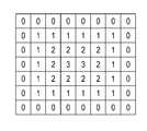
제1 필터링부(123c)는 제1 마스킹부(123b)에서 마스킹 처리된 속도 영상에 거리 가중치 및 경계 평활화 처리를 수행한다. 여기서, 거리 가중치 처리는 혈관 경계 부분의 혈류 속도가 혈관 중앙 부분의 혈류 속도보다 낮게 표현되도록 하는 처리이다. 제1 필터링부(123c)는 제1 마스킹부(123b)에서 마스킹 처리된 속도 영상을 이용하여 거리변환영상을 형성한다. 거리변환영상은 도 6에 도시된 바와 같이 배경, 즉 혈관 이외의 화소에 0의 값을 설정하고, 나머지 화소에 배경과의 최소거리값을 인가하여 얻은 영상이다. 거리변환영상의 화소값이 i이면, 이 화소에 해당하는 거리 가중치는 화소값의 함수로 정할 수 있다. 일례로서, 거리 가중치는 w(i)=min(i*0.2+0.6, 1)와 같이 정할 수 있다. 따라서, 평활화 처리된 속도 영상의 화소값이 f(x,y)이면, 이 화소값은 거리 가중치를 통해 f(x,y)*w(f(x,y)로 변경된다. 아울러, 제1 필터링부(123c)는 거리 가중치 처리된 속도 영상에서 혈관 경계 부분을 검출하고, 검출된 경계 부분에 대해 평활화 처리를 수행한다.The
피크 복원부(123d)는 제1 필터링부(123c)로부터 제공되는 속도 영상에 피크 복원을 수행한다. 혈관 내에서 혈류의 최대속도(피크)는 임상적으로 중요한 정보를 제공하므로 피크가 유지되어야 한다. 그러나, 평활화 과정에서 피크가 블러링되어 피크값이 작아지게 된다. 따라서, 피크 복원부(123d)는 영상 처리부(121)로부터 제공되는 속도 영상과 제1 필터링부(123c)에서 평활화 처리된 속도 영상 간의 차 영 상을 구한다. 피크 복원부(123d)는 차 영상에서 값이 0 이상인 영역인 피크 후보를 검출하고, 검출된 후보 피크에서 사전 설정된 임계값을 초과하는 영역을 피크 영역으로서 검출한다. 피크 복원부(123d)는 검출된 피크 영역을 이용하여 제1 필터링부(123c)에서 평활화 처리된 속도 영상에 피크 복원을 수행한다.The
제2 영상 처리부(124)는 마스크 형성부(122)로부터 제공되는 마스크를 이용하여 영상 형성부(121)로부터 순차적으로 제공되는 파워 영상에 마스킹 처리를 수행한다. 본 실시예에서 제2 영상 처리부(124)는 제2 평활화부(124a), 제2 마스킹부(124b) 및 제2 필터링부(124c)를 포함한다.The
제2 평활화부(124a)는 영상 형성부(121)로부터 파워 영상이 제공되면, 파워 영상에 평활화 처리를 수행한다. 평활화는 공지된 다양한 방법이 사용될 수 있다. 일례로서, 평활화는 평균 필터링, 가우시안 필터링, 메디안 필터링, 저역통과 필터링, 그래프 정규화(regularization) 등이 사용될 수 있다.When the power image is provided from the
제2 마스킹부(124b)는 마스크 형성부(122)로부터 제공되는 마스크를 이용하여 제2 평활화부(124a)에서 평활화 처리된 파워 영상에 마스킹 처리를 수행한다. 즉, 제2 마스킹부(124b)는 마스크 형성부(122)로부터 제공되는 마스크를 이용하여 파워 영상의 각 화소에 대해 혈관에 해당하는 영역을 1로 설정하고, 혈관 이외의 영역을 0으로 설정하는 마스킹 처리를 파워 영상에 수행한다.The
제2 필터링부(124c)는 제2 마스킹부(124b)에서 마스킹 처리된 파워 영상에 거리 가중치 및 경계 평활화 처리를 수행한다. 여기서, 거리 가중치 처리는 혈관 경계 부분의 파워가 혈관 중앙 부분의 파워보다 낮게 표현되도록 하는 처리이다. 제2 필터링부(124c)는 제2 마스킹부(124b)에서 마스킹 처리된 파워 영상을 이용하여 거리변환영상을 형성한다. 아울러, 제2 필터링부(124c)는 거리 가중치 처리된 파워 영상에서 혈관 경계 부분을 검출하고, 검출된 경계 부분에 대해 평활화 처리를 수행한다.The
다시 도 1을 참조하면, 디스플레이부(130)는 프로세서(120)에서 형성된 컬러 도플러 모드 영상, 즉 파워 영상 및 속도 영상을 디스플레이한다. 제어부(140)는 도플러 신호의 획득을 제어한다. 아울러, 제어부(140)는 파워 영상 및 속도 영상의 형성, 영상 처리 및 디스플레이를 제어한다.Referring back to FIG. 1, the
본 발명이 바람직한 실시예를 통해 설명되고 예시되었으나, 당업자라면 첨부된 특허청구범위의 사항 및 범주를 벗어나지 않고 여러 가지 변경 및 변형이 이루어질 수 있음을 알 수 있을 것이다.While the invention has been described and illustrated by way of preferred embodiments, those skilled in the art will recognize that various changes and modifications can be made therein without departing from the spirit and scope of the appended claims.
일례로서, 전술한 실시예에서는 파워 영상을 이용하여 마스크를 형성하는 것으로 설명하였지만, 다른 실시예에서는 속도 영상을 이용하여 마스크를 형성할 수도 있다.As an example, in the above-described embodiment, a mask is formed using a power image, but in another embodiment, a mask may be formed using a speed image.
도 1은 본 발명의 실시예에 따른 초음파 시스템의 구성을 보이는 블록도.1 is a block diagram showing the configuration of an ultrasonic system according to an embodiment of the present invention.
도 2는 본 발명의 실시예에 따른 신호 획득부의 구성을 보이는 블록도.Figure 2 is a block diagram showing the configuration of a signal acquisition unit according to an embodiment of the present invention.
도 3은 본 발명의 실시예에 따른 프로세서의 구성을 보이는 블록도.3 is a block diagram showing a configuration of a processor according to an embodiment of the present invention.
도 4는 본 발명의 실시예에 따른 복수의 파워 영상, 파워 평균값 및 합성 영상을 보이는 예시도.4 is an exemplary view showing a plurality of power images, a power average value and a synthesized image according to an embodiment of the present invention.
도 5a는 본 발명의 실시예에 따라 마스크를 설정하는 예를 보이는 예시도.5A is an exemplary view showing an example of setting a mask according to an embodiment of the present invention.
도 5b는 본 발명의 실시예에 따라 마스크의 외곽을 검출하는 예를 보이는 예시도.Figure 5b is an exemplary view showing an example of detecting the outside of the mask in accordance with an embodiment of the present invention.
도 5c는 본 발명의 실시예에 따라 마스크 외곽에 평활화 처리를 수행하는 예를 보이는 예시도.5C is an exemplary view showing an example of performing a smoothing process on the outside of a mask according to an embodiment of the present invention.
도 5d는 본 발명에 실시예에 따라 마스크에 채우기(filling) 처리를 수행하는 예를 보이는 예시도.5D is an exemplary view showing an example of performing a filling process on a mask according to an embodiment of the present invention.
도 6은 본 발명의 실시예에 따른 거리변환영상의 예를 보이는 예시도.6 is an exemplary view showing an example of a distance conversion image according to an embodiment of the present invention.
Claims (15)
Translated fromKoreanPriority Applications (4)
| Application Number | Priority Date | Filing Date | Title |
|---|---|---|---|
| KR1020090038474AKR101138613B1 (en) | 2009-04-30 | 2009-04-30 | Ultrasound system and method for processing color doppler mode image |
| EP10160682.0AEP2249175B1 (en) | 2009-04-30 | 2010-04-22 | Color doppler mode image processing in an ultrasound system |
| US12/767,300US8500646B2 (en) | 2009-04-30 | 2010-04-26 | Color Doppler mode image processing in an ultrasound system |
| JP2010104141AJP5576703B2 (en) | 2009-04-30 | 2010-04-28 | Ultrasound system and method for processing color Doppler mode images |
Applications Claiming Priority (1)
| Application Number | Priority Date | Filing Date | Title |
|---|---|---|---|
| KR1020090038474AKR101138613B1 (en) | 2009-04-30 | 2009-04-30 | Ultrasound system and method for processing color doppler mode image |
Publications (2)
| Publication Number | Publication Date |
|---|---|
| KR20100119387A KR20100119387A (en) | 2010-11-09 |
| KR101138613B1true KR101138613B1 (en) | 2012-04-26 |
Family
ID=42320947
Family Applications (1)
| Application Number | Title | Priority Date | Filing Date |
|---|---|---|---|
| KR1020090038474AActiveKR101138613B1 (en) | 2009-04-30 | 2009-04-30 | Ultrasound system and method for processing color doppler mode image |
Country Status (4)
| Country | Link |
|---|---|
| US (1) | US8500646B2 (en) |
| EP (1) | EP2249175B1 (en) |
| JP (1) | JP5576703B2 (en) |
| KR (1) | KR101138613B1 (en) |
Cited By (1)
| Publication number | Priority date | Publication date | Assignee | Title |
|---|---|---|---|---|
| KR101610877B1 (en) | 2014-04-28 | 2016-04-21 | 주식회사 웨이전스 | Module for Processing Ultrasonic Signal Based on Spatial Coherence and Method for Processing Ultrasonic Signal |
Families Citing this family (6)
| Publication number | Priority date | Publication date | Assignee | Title |
|---|---|---|---|---|
| KR101121548B1 (en)* | 2009-12-07 | 2012-03-06 | 삼성메디슨 주식회사 | Ultrasonic Diagnostic Device |
| KR101313220B1 (en)* | 2010-11-23 | 2013-09-30 | 삼성메디슨 주식회사 | Ultrasound system and method for providing color doppler mode image based on qualification curve |
| JP5972691B2 (en)* | 2012-07-09 | 2016-08-17 | 東芝メディカルシステムズ株式会社 | Ultrasonic diagnostic apparatus, image processing apparatus, and program |
| EP3533027B1 (en)* | 2016-10-28 | 2021-04-14 | Koninklijke Philips N.V. | Automatic ct detection and visualization of active bleeding and blood extravasation |
| CN110313939B (en)* | 2019-08-01 | 2020-12-11 | 无锡海斯凯尔医学技术有限公司 | Tissue region-of-interest positioning method, device, equipment and storage medium |
| US12364460B2 (en)* | 2020-08-25 | 2025-07-22 | Clarius Mobile Health Corp. | Systems and methods for placing a gate and/or a color box during ultrasound imaging |
Citations (2)
| Publication number | Priority date | Publication date | Assignee | Title |
|---|---|---|---|---|
| EP0087104A1 (en)* | 1982-02-22 | 1983-08-31 | PUMA-Sportschuhfabriken Rudolf Dassler KG | Sports shoe with an elastic exterior sole of plastics material |
| US20030181814A1 (en)* | 2002-03-19 | 2003-09-25 | Ting-Lan Ji | System and method for post-processing ultrasound color doppler imaging |
Family Cites Families (11)
| Publication number | Priority date | Publication date | Assignee | Title |
|---|---|---|---|---|
| JPH02268748A (en)* | 1989-04-11 | 1990-11-02 | Yokogawa Medical Syst Ltd | Ultrasonic blood flow imaging apparatus |
| US5860929A (en)* | 1996-06-07 | 1999-01-19 | The Regents Of The University Of Michigan | Fractional moving blood volume estimation with power doppler ultrasound |
| JPH1075955A (en)* | 1996-07-11 | 1998-03-24 | Fujitsu Ltd | Ultrasound diagnostic equipment |
| US5921931A (en)* | 1997-04-08 | 1999-07-13 | Endosonics Corporation | Method and apparatus for creating a color blood flow image based upon ultrasonic echo signals received by an intravascular ultrasound imaging probe |
| US6352509B1 (en)* | 1998-11-16 | 2002-03-05 | Kabushiki Kaisha Toshiba | Three-dimensional ultrasonic diagnosis apparatus |
| JP4574768B2 (en)* | 1998-11-16 | 2010-11-04 | 株式会社東芝 | 3D ultrasonic diagnostic equipment |
| US6217520B1 (en)* | 1998-12-02 | 2001-04-17 | Acuson Corporation | Diagnostic medical ultrasound system and method for object of interest extraction |
| JP3683886B2 (en)* | 2002-12-27 | 2005-08-17 | 株式会社ワイディ | Blood volume analysis and display method using Myo Cardial Blood volume map |
| JP2006141798A (en)* | 2004-11-22 | 2006-06-08 | Toshiba Corp | Ultrasonic diagnostic equipment |
| JP2008154891A (en) | 2006-12-26 | 2008-07-10 | Ge Medical Systems Global Technology Co Llc | Color doppler apparatus and ultrasonic imaging apparatus |
| EP2173253A2 (en)* | 2007-07-26 | 2010-04-14 | Koninklijke Philips Electronics N.V. | Systems and methods for automated image selection in doppler ultrasound imaging systems |
- 2009
- 2009-04-30KRKR1020090038474Apatent/KR101138613B1/enactiveActive
- 2010
- 2010-04-22EPEP10160682.0Apatent/EP2249175B1/enactiveActive
- 2010-04-26USUS12/767,300patent/US8500646B2/enactiveActive
- 2010-04-28JPJP2010104141Apatent/JP5576703B2/ennot_activeExpired - Fee Related
Patent Citations (2)
| Publication number | Priority date | Publication date | Assignee | Title |
|---|---|---|---|---|
| EP0087104A1 (en)* | 1982-02-22 | 1983-08-31 | PUMA-Sportschuhfabriken Rudolf Dassler KG | Sports shoe with an elastic exterior sole of plastics material |
| US20030181814A1 (en)* | 2002-03-19 | 2003-09-25 | Ting-Lan Ji | System and method for post-processing ultrasound color doppler imaging |
Cited By (1)
| Publication number | Priority date | Publication date | Assignee | Title |
|---|---|---|---|---|
| KR101610877B1 (en) | 2014-04-28 | 2016-04-21 | 주식회사 웨이전스 | Module for Processing Ultrasonic Signal Based on Spatial Coherence and Method for Processing Ultrasonic Signal |
Also Published As
| Publication number | Publication date |
|---|---|
| US8500646B2 (en) | 2013-08-06 |
| JP2010259794A (en) | 2010-11-18 |
| KR20100119387A (en) | 2010-11-09 |
| EP2249175B1 (en) | 2014-06-11 |
| EP2249175A1 (en) | 2010-11-10 |
| JP5576703B2 (en) | 2014-08-20 |
| US20100280383A1 (en) | 2010-11-04 |
Similar Documents
| Publication | Publication Date | Title |
|---|---|---|
| CN114375178B (en) | Method for high spatial and temporal resolution ultrasound imaging of microvasculature | |
| KR101138613B1 (en) | Ultrasound system and method for processing color doppler mode image | |
| JP4787358B2 (en) | Ultrasonic diagnostic equipment | |
| US9585636B2 (en) | Ultrasonic diagnostic apparatus, medical image processing apparatus, and medical image processing method | |
| EP2793703B1 (en) | Method for visualizing blood and blood-likelihood in vascular images | |
| JP5627706B2 (en) | Ultrasonic imaging device, ultrasonic imaging program | |
| JP2020531074A (en) | Ultrasound system with deep learning network for image artifact identification and removal | |
| JP4627366B2 (en) | Method and apparatus for motion visualization in ultrasonic flow imaging using packet data acquisition | |
| CN109952063B (en) | System and method for characterizing liver perfusion of a contrast agent flow | |
| US10101450B2 (en) | Medical image processing apparatus, a medical image processing method and a medical diagnosis apparatus | |
| JP5984243B2 (en) | Ultrasonic diagnostic apparatus, medical image processing apparatus, and program | |
| CN111265246B (en) | Ultrasonic color imaging processing method and device | |
| US9204861B2 (en) | Ultrasound diagnostic apparatus and method of determining a time intensity curve | |
| KR101120700B1 (en) | Ultrasound system and method for providing color doppler mode image | |
| JP7305438B2 (en) | Analysis device and program | |
| JP3802462B2 (en) | Ultrasonic diagnostic equipment | |
| WO2006015264A2 (en) | T-statistic method for suppressing artifacts in blood vessel ultrasonic imaging | |
| EP2189116B1 (en) | Adaptive persistence processing of elastic images | |
| JP6444519B2 (en) | Ultrasonic diagnostic apparatus and ultrasonic imaging method | |
| JP5595988B2 (en) | Ultrasonic diagnostic apparatus and image quality improving method of ultrasonic diagnostic apparatus | |
| WO2024262106A1 (en) | Ultrasonic diagnostic device, medical information processing device, information processing method, and program | |
| JP2025070977A (en) | Ultrasound diagnostic device, image processing device, and image processing method | |
| JP2025059036A (en) | Ultrasound diagnostic device, medical information processing device, and medical information processing method | |
| Zhou et al. | Speckle reduction of ultrasound elastography with bilateral filter | |
| KR20110129666A (en) | Ultrasound System and Method for Improving Image Quality of Color Doppler Mode Images |
Legal Events
| Date | Code | Title | Description |
|---|---|---|---|
| PA0109 | Patent application | Patent event code:PA01091R01D Comment text:Patent Application Patent event date:20090430 | |
| A201 | Request for examination | ||
| PA0201 | Request for examination | Patent event code:PA02012R01D Patent event date:20100421 Comment text:Request for Examination of Application Patent event code:PA02011R01I Patent event date:20090430 Comment text:Patent Application | |
| PG1501 | Laying open of application | ||
| E902 | Notification of reason for refusal | ||
| PE0902 | Notice of grounds for rejection | Comment text:Notification of reason for refusal Patent event date:20110719 Patent event code:PE09021S01D | |
| E701 | Decision to grant or registration of patent right | ||
| PE0701 | Decision of registration | Patent event code:PE07011S01D Comment text:Decision to Grant Registration Patent event date:20120330 | |
| GRNT | Written decision to grant | ||
| PR0701 | Registration of establishment | Comment text:Registration of Establishment Patent event date:20120416 Patent event code:PR07011E01D | |
| PR1002 | Payment of registration fee | Payment date:20120417 End annual number:3 Start annual number:1 | |
| PG1601 | Publication of registration | ||
| FPAY | Annual fee payment | Payment date:20160330 Year of fee payment:5 | |
| PR1001 | Payment of annual fee | Payment date:20160330 Start annual number:5 End annual number:5 | |
| FPAY | Annual fee payment | Payment date:20170412 Year of fee payment:6 | |
| PR1001 | Payment of annual fee | Payment date:20170412 Start annual number:6 End annual number:6 | |
| FPAY | Annual fee payment | Payment date:20180404 Year of fee payment:7 | |
| PR1001 | Payment of annual fee | Payment date:20180404 Start annual number:7 End annual number:7 | |
| FPAY | Annual fee payment | Payment date:20190327 Year of fee payment:8 | |
| PR1001 | Payment of annual fee | Payment date:20190327 Start annual number:8 End annual number:8 | |
| PR1001 | Payment of annual fee | Payment date:20200406 Start annual number:9 End annual number:9 | |
| PR1001 | Payment of annual fee | Payment date:20210329 Start annual number:10 End annual number:10 | |
| PR1001 | Payment of annual fee | Payment date:20220329 Start annual number:11 End annual number:11 | |
| PR1001 | Payment of annual fee | Payment date:20240326 Start annual number:13 End annual number:13 | |
| PR1001 | Payment of annual fee | Payment date:20250325 Start annual number:14 End annual number:14 |