KR101136674B1 - Pixel shifting color projection system - Google Patents
Pixel shifting color projection systemDownload PDFInfo
- Publication number
- KR101136674B1 KR101136674B1KR1020067007302AKR20067007302AKR101136674B1KR 101136674 B1KR101136674 B1KR 101136674B1KR 1020067007302 AKR1020067007302 AKR 1020067007302AKR 20067007302 AKR20067007302 AKR 20067007302AKR 101136674 B1KR101136674 B1KR 101136674B1
- Authority
- KR
- South Korea
- Prior art keywords
- light
- pixels
- color
- shift
- integrator
- Prior art date
- Legal status (The legal status is an assumption and is not a legal conclusion. Google has not performed a legal analysis and makes no representation as to the accuracy of the status listed.)
- Expired - Fee Related
Links
Images


Classifications
- H—ELECTRICITY
- H04—ELECTRIC COMMUNICATION TECHNIQUE
- H04N—PICTORIAL COMMUNICATION, e.g. TELEVISION
- H04N9/00—Details of colour television systems
- H04N9/12—Picture reproducers
- H04N9/31—Projection devices for colour picture display, e.g. using electronic spatial light modulators [ESLM]
- G—PHYSICS
- G03—PHOTOGRAPHY; CINEMATOGRAPHY; ANALOGOUS TECHNIQUES USING WAVES OTHER THAN OPTICAL WAVES; ELECTROGRAPHY; HOLOGRAPHY
- G03B—APPARATUS OR ARRANGEMENTS FOR TAKING PHOTOGRAPHS OR FOR PROJECTING OR VIEWING THEM; APPARATUS OR ARRANGEMENTS EMPLOYING ANALOGOUS TECHNIQUES USING WAVES OTHER THAN OPTICAL WAVES; ACCESSORIES THEREFOR
- G03B21/00—Projectors or projection-type viewers; Accessories therefor
- G03B21/14—Details
- G03B21/20—Lamp housings
- G03B21/208—Homogenising, shaping of the illumination light
- H—ELECTRICITY
- H04—ELECTRIC COMMUNICATION TECHNIQUE
- H04N—PICTORIAL COMMUNICATION, e.g. TELEVISION
- H04N9/00—Details of colour television systems
- H04N9/12—Picture reproducers
- H04N9/31—Projection devices for colour picture display, e.g. using electronic spatial light modulators [ESLM]
- H04N9/3102—Projection devices for colour picture display, e.g. using electronic spatial light modulators [ESLM] using two-dimensional electronic spatial light modulators
- H04N9/3111—Projection devices for colour picture display, e.g. using electronic spatial light modulators [ESLM] using two-dimensional electronic spatial light modulators for displaying the colours sequentially, e.g. by using sequentially activated light sources
- H04N9/3114—Projection devices for colour picture display, e.g. using electronic spatial light modulators [ESLM] using two-dimensional electronic spatial light modulators for displaying the colours sequentially, e.g. by using sequentially activated light sources by using a sequential colour filter producing one colour at a time
Landscapes
- Engineering & Computer Science (AREA)
- Multimedia (AREA)
- Signal Processing (AREA)
- Physics & Mathematics (AREA)
- General Physics & Mathematics (AREA)
- Projection Apparatus (AREA)
- Video Image Reproduction Devices For Color Tv Systems (AREA)
Abstract
Translated fromKoreanDescription
Translated fromKorean관련출원에 대한 상호참조Cross-reference to related application
본 출원은 2003년 10월 16일에 출원된 "Pixel Shift Wheel for Displays Employing Microdisplays"라는 발명의 명칭의 미국 가특허출원 제60/511,801(대리인 문서 번호 PU030291), 2003년 10월 16일 출원된 "Resolution Enhanced Dot Sequential Display"라는 발명의 명칭의 미국 가특허출원 제60/511,872호(대리인 문서 번호 PU030292), 및 2003년 10월 16일 출원된 "Minimum Motion Color System for DLP Like Systems"라는 발명의 명칭의 미국 가특허출원 제 60/511,958호(대리인 문서 번호 PU030293)의 권리를 주장하며, 이들은 모두 본 명세서에서 전체로서 참조된다.This application is filed on October 16, 2003, entitled "Pixel Shift Wheel for Displays Employing Microdisplays," US Provisional
본 발명은 전반적으로 투사 시스템에 관한 것으로, 보다 구체적으로는 이산적인 컬러 픽셀들의 패턴이 시프트되는 마이크로 디스플레이(micro-display)를 포함하는 투사 시스템에 관한 것이다.The present invention relates generally to a projection system, and more particularly to a projection system comprising a micro-display in which a pattern of discrete color pixels is shifted.
DLP 이미저(digital light pulse imager)와 같은 반사광 엔진 또는 이미저를 이용하는 마이크로 디스플레이 투사 시스템은 (예컨대, RPTV(rear projection television)와 같은)컬러 이미지 또는 비디오 투사 장치들에서 점점 더 많이 이용 되고 있다. 도 1에 도시된 기존 투사 시스템에서, 본 경우에 백색광(즉, 모든 색 스펙트럼)을 생성하는 UHP 램프와 같은 광원(10)이 제공된다. 광원(10)으로부터의 광은 각기 청색, 녹색 및 적색 중 하나의 색의 광 밴드(band)가 통과하고 다른 색의 광은 반사하는 것을 가능하게 하는 다수의 다이크로익 필터링 소자(dichroic filtering element)들을 포함하는 컬러 휠(20)을 통과한다. 컬러 휠(20)은 청색, 녹색 및 적색 광 밴드의 일시적인 패턴이 컬러 휠을 통과하도록 회전된다. 컬러 휠은 전형적으로 비디오 이미지의 각각의 프레임 동안에 각각의 원색에 대하여 적어도 하나의 원색 주기를 생성하기에 충분한 정도로 빨리 회전된다. 휠을 보다 빨리 회전시키거나, 하나 이상의 원색들에 대하여 다수의 필터 세그먼트들을 이용함으로써, 보는 사람이 디스플레이 시스템의 순차적인 색 특성을 검출하는 것을 가능하게 하는 색 분리 아티팩트(artifact)를 생성할 수 있다. 예컨대, 색 분리, 또는 무지개 효과는 색들이 순차적으로 번쩍이는 회전하는 색 휠을 통과하는 광에 의해서 야기되며, 스크린의 한쪽에서 다른 쪽으로 빨리 볼 때에, 또는 스크린으로부터 스크린 밖으로 멀어지는 물체를 빨리 볼 때에 무지개 유사한 줄무늬의 순간적인 번쩍임으로 나타난다. 추가적으로, 스크린을 가로지르는 이동체의 선두 예지에서, 순차적인 색 광 빔에서의 3원색 중 하나의 번쩍임으로 나타나는 색 에지 효과는 색 분리 아티팩트 또한 생성할 수 있을 것이다.BACKGROUND OF THE INVENTION Micro display projection systems using a reflected light engine or imager such as a DLP imager (digital light pulse imager) are increasingly used in color image or video projection devices (such as a rear projection television (RPTV)). In the conventional projection system shown in FIG. 1, in this case a
인티그레이터(integrator; 30)는 광원(10)으로부터 색 휠(20)을 통과하도록 허용된 광 밴드를 수신하여 이러한 광 밴드를 중계 광학소자를 통해서 TIR(total internal reflection) 프리즘(50)으로 보낸다. TIR 프리즘(50)은 광 밴드를 DLP 이미저와 같은 이미저(60) 상에 반사한다. 이미저는 광빔의 개별적인 픽셀들의 세기를 변조시키고, 이들을 TIR 프리즘(50)을 통해서 투사 렌즈 시스템(70)으로 다시 반사한다. 투사 렌즈 시스템(70)은 광 픽셀들을 스크린(도시되지 않음) 상에 촛점을 맞추어 가시 이미지를 형성한다. 컬러 비디오 이미지는 전체 컬러 이미지를 형성하기 위하여 보는 사람의 시각에 의해서 블랜딩된 각각의 3색(청색, 녹색, 적색)의 픽셀들의 신속한 연속적인 매트릭스들에 의해서 형성된다.
본 명세서 전반에 걸쳐, 그리고, 관련 기술의 실제와 일치하도록, 픽셀이라는 용어는 이미지의 작은 영역 또는 도트(dot), 광 전달의 그 대응 부분 및 그러한 광 전달을 생성하는 이미지의 부분을 가리키는 데에 사용된다.Throughout this specification, and to coincide with the practice of the related art, the term pixel is used to refer to a small area or dot of an image, its corresponding portion of light transmission, and the portion of the image that produces such light transmission. Used.
DLP 이미저(60)는 TIR 프리즘을 통하여 투사 렌트 시스템(70)으로 반사하는 각과 투사 렌즈 시스템(70)에 의해서 투사되지 않도록 광을 굴절시키는 각 사이에서 이동가능한 마이크로 미러(micro-mirrors)들 의 매트릭스를 포함한다. 각각의 마이크로 미러는 차례로 DLP 이미저(60)에 어드레싱된 비디오 신호에 응답하는 그러한 특정 마이크로 미러의 각의 연속에 따라 원하는 세기의 광의 픽셀을 반사한다. 따라서, DLP 이미저(60)에서 이미저의 각각의 마이크로 미러 또는 픽셀은 이미저 또는 광 엔진에 입력되는 그레이 스케일 인자에 따라 입사되는 광을 변조하여 이산 변조된 광 신호들 또는 픽셀들의 매트릭스를 형성한다.The
그러나, 기존 DLP 이미저는 몇몇 문제점을 가진다. 반사된 색들을 가지는 광이 전형적으로 소실되기 때문에, 색 휠은 광을 낭비한다. 또한, 전술한 바와 같이 색 분리 또는 분리 아티팩트는 투사 시스템의 이미지 질을 저하시킨다. 추가적 으로, 각각의 마이크로 미러는 각각의 프레임에 대한 각각의 3가지 색 밴드들에 대하여 12배까지 피벗(pivot)하여 프레임 속도를 제한하고, 기계적 신뢰도에 불리하게 작용한다. 이처럼, 색 분리 또는 분리 아티팩트를 감소시키고/감소시키거나 향상된 해방도 및 향상된 신뢰도를 가지는 시스템이 요구된다.However, existing DLP imagers have some problems. Since light with reflected colors is typically lost, the color wheel wastes light. In addition, color separation or separation artifacts, as described above, degrade the image quality of the projection system. In addition, each micromirror pivots up to 12 times for each of the three color bands for each frame to limit the frame rate and adversely affect mechanical reliability. As such, there is a need for a system that reduces and / or reduces color separation or separation artifacts and that has improved liberation and improved reliability.
본 발명은 마이크로 디스플레이를 이용하여 전체 색 이미지를 투사하는, 감소된 기계적 움직임 및/또는 향상된 해상도를 가지는 투사 시스템을 제공한다. 예시적인 실시예에서, 투사 시스템은 출력 윈도우들의 매트릭스를 구비하는 출력 단부를 가지는 인티그레이터를 가진다. 이미저는 광의 픽셀들을 변조한다. 광 시프트 장치는 광의 픽셀들의 매트릭스를 시프트하여, 색 이미저로 볼 수 있는 중첩하는 상이한 색의 광의 단색 픽셀들의 패턴을 일시적으로 형성하고/형성하거나, 이전에 투사된 광의 픽셀들의 위치들 사이의 광의 픽셀들을 투사하여 해상도를 향상시킨다.The present invention provides a projection system with reduced mechanical motion and / or improved resolution that projects a full color image using a micro display. In an exemplary embodiment, the projection system has an integrator having an output end having a matrix of output windows. The imager modulates the pixels of light. The light shifting device shifts the matrix of pixels of light to temporarily form a pattern of monochromatic pixels of overlapping different colored light that can be seen with a color imager, and / or to adjust the light between the positions of pixels of previously projected light. Project pixels to improve resolution.
이제, 본 발명은 첨부된 도면을 참조하여 기술될 것이다.The invention will now be described with reference to the accompanying drawings.
도 1은 기존 DLP(digital light pulse) 투사 시스템의 다이어그램.1 is a diagram of a conventional digital light pulse (DLP) projection system.
도 2는 본 발명의 일 실시예에 따른 투사 시스템의 다이어그램.2 is a diagram of a projection system in accordance with an embodiment of the present invention.
도 3은 도 2의 투사 시스템으로부터의 인티그레이터의 입력 단부의 단부도.3 is an end view of the input end of the integrator from the projection system of FIG.
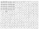
도 4는 도 2 및 3의 인티그레이터의 출력 단부의 단부도로서, 인티그레이터의 출력 윈도우 상의 단색 필터들의 패턴을 나타내는 도면.4 is an end view of the output end of the integrator of FIGS. 2 and 3, showing a pattern of monochrome filters on the output window of the integrator;
도 5는 도 3의 인티그레이터의 입력 윈도우를 도시하는 도면.5 shows an input window of the integrator of FIG.
도 6은 도 2의 투사 시스템에 의해서 투사되는 중첩 픽셀들의 패턴을 도시하는 도면.6 shows a pattern of overlapping pixels projected by the projection system of FIG.
도 7은 본 발명의 다른 예시적인 실시예에 따른 투사 시스템의 다이어그램.7 is a diagram of a projection system according to another exemplary embodiment of the present invention.
도 8은 도 7의 투사 시스템에 대한 인티그레이터의 출력 단부의 단부도로서, 인티그레이터의 출력 윈도우들 상의 단색 필터들의 패턴을 나타내는 도면.FIG. 8 is an end view of the output end of the integrator for the projection system of FIG. 7 showing a pattern of monochromatic filters on the output windows of the integrator. FIG.
도 9는 연속적인 색 충진을 나타내는 도 7의 투사 시스템에 대한 이미저 출력을 도시하는 도면.9 illustrates imager output for the projection system of FIG. 7 showing continuous color filling.
도 10은 본 발명의 다른 실시예에 따른 투사 시스템의 다이어그램.10 is a diagram of a projection system according to another embodiment of the present invention.
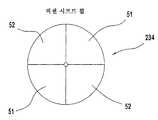
도 11 및 12는 도 10의 투사 시스템으로부터의 픽셀 시프트 휠의 평면도 및 측면도를 각기 도시하는 도면.11 and 12 show top and side views, respectively, of a pixel shift wheel from the projection system of FIG.
본 발명은 단색 픽셀들의 패턴의 시프트에 기인하여 향상된 해상도 및/또는 감소된 투사 시스템의 기계적인 동작을 가지는, 예를 들어 텔레비전 디스플레이용의, 비디오 이미지 투사를 위한 색 투사 시스템을 제공한다. 도 2에 도시된 바와 같은 예시적인 실시예에서, 백색광이 램프(110)에 의해서 생성되어 파라볼라 반사기(parabolic reflector, 111)에 의해서 인티그레이터(integrator; 120)로 보내어진다. 예시적인 실시예에서, 램프(110)는 투사 디스플레이 시스템에서 사용하기 적합한 강한 세기의 다수의 파장 출력 램프이다. 이러한 목적의 적절한 램프(110)는 투사 디스플레이용 광원으로 본 기술 분야에 잘 알려진 UHP 램프이다. 램프(110)의 광 출력은 인티그레이터(120)에 결합된다. 인티그레이터(120)는 램프의 광 출력을 소정의 직사각형 종횡비 및 이미저(140)의 크기에 상응하는 크기로 이미저(140)로 보내는 사각주로 형성된다. 이러한 실시예에 있어서, 인티그레이터(120)는 실질적으로 전체에 연장하는 은 피복과 같은 반사 피복을 가지는 주변 표면(126)을 가진다. 도 5를 참조하면, 인티그레이터(120)의 입력 단부(122)는 선택적으로 도포되어 램프로부터의 광이 통과하는 투과부(125) 및 광을 주변 표면(126) 내부를 따라 내부적으로 반사하는 반사부(123)를 형성하는 유사한 반사 피복을 가진다. 유사하게, 도 3을 참조하면, 출력 단부(128)는 반사부(127) 및 다수의 투과부들 또는 윈도우들(123)을 가지도록 형성된다. 윈도우들(123)은 출력 단부(128)를 통해서 내부로부터 광이 통과될 수 있는 다수의 개구들일 수 있을 것이다. 각각의 윈도우(123)는 광의 선택된 색 또는 밴드의 통과는 허용하고, 이를 통과하는 광의 다른 색들은 차단하는 데에 이용되는 필터(124)를 가진다. 예컨대, 도 4에 도시된 바와 같이, 필터들(124R)은 인티그레이터(120)로부터 적색 광의 통과를 허용하며, 필터들(124B)은 인티그레이터(120)로부터 청색 광의 통과를 허용하며, 필터들(124G)는 인티그레이터(120)로부터 녹색 광의 통과를 허용한다. 따라서, 본 기술 분야의 당업자는 각각의 윈도우(123)가 선택된 윈도우들(123)에 대하여 선택된 필터들(124)을 이용함으로써 동일한 색 광을 투과하도록 선택될 수 있음을 이해할 수 있을 것이다. 반사부들(127)은 입사광을 인티그레이터(120) 및 내부 표면으로 다시 반사하여 종국적으로 출력 단부를 향하여 윈도우(123)를 통해서 다시 보내는 역할을 함 또한 이해될 수 있을 것이다. 이것은 조명을 보존하고 인티그레이터(120)를 통한 광 감쇠를 감소시키는 역할을 한다.The present invention provides a color projection system for projecting video images, for example for television displays, with improved resolution and / or reduced mechanical operation of the projection system due to the shift of the pattern of monochrome pixels. In the exemplary embodiment as shown in FIG. 2, white light is generated by the
도 3에 도시된 바와 같이, 출력 윈도우들(123)의 매트릭스는 인티그레이터(120)의 출력 단부(128)에 위치하며, 직사각형 그리드(rectangular grid) 내에 배열된다. 각각의 출력 윈도우(123)는 청색, 녹색 및 적색의 색 밴드 중 하나를 투과시키고 다른 색 밴드들은 반사하는, 그와 관련된 단색 필터(124)를 가진다. 단색 필터들은 본 기술 분야에 공지되어 있는 것으로, 여기서 더 이상 기술되지 않을 것이다. 출력 윈도우들(123)은 이후에 기술될 바와 같이 1 대 1 단위로 DLP 이미저의 마이크로 미러들과 대응하며, 개별적인 마이크로 미러들 이하의 크기를 가진다. 따라서, 각각의 필터링된 윈도우는 개별적인 마이크로 미러의 크기 이하의 단색 광의 픽셀을 통과시킨다.As shown in FIG. 3, the matrix of
예시적인 실시예에서, 단색 필터들(124)이 도 4에 도시된 색 패턴으로 제공된다. 출력 윈도우들(123)의 제1 행은 각각 적색 및 녹색 광만을 통과시키거나 투과시키는 교대하는 적색 필터들(124R)과 녹색 필터들(124G)을 가진다. 출력 윈도우들(123)의 제2 행은, 각각 녹색 및 청색 광만을 통과시키거나 투과시키는 교대하는 녹색 필터들(124G) 및 청색 필터들(124B)을 가진다. 제3 행은 제1 행과 동일하며, 제4 행은 제2 행과 동일하며, 이하 마찬가지이다. 필터들(124)은 각각의 적색 필터(24R) 및 각각의 청색 필터(124B)가 녹색 필터들(124G)에 수평 및 수직 방향으로 인접하도록 위치한다.In an exemplary embodiment,
도 2를 참조하면, 필터링된 출력 윈도우(123)는 중계 광학 시스템(130)을 통해서 이미저(140) 상에 변하는 색들의 단색 광 픽셀들의 매트릭스를 통과시킨다. 이미저(140)는 이미저(140)에 어드레스되는 비디오 신호에 응답하여 단색 광 픽셀들의 매트릭스를 픽셀 단위로 변조한다. 본 명세서에 도시되고 기술되는 실시예에서, 이미저(140)는 DMD(digital micro-display)로서, 보다 구체적으로는 마이크로 미러들의 직사각형 그리드를 포함하여 이미저의 픽셀에 대하여 제공되는 신호에 따라 마이크로 미러 상에 입사되는 광의 픽셀을 투사 경로를 따라 편향시키거나, 투사 경로로부터 멀어지도록 편향시키는 DLP 이미저이다. 각각의 마이크로 미러는 소정의 횟수만큼 위치하여(즉, 변조 싸이클에서 소정의 수의 비트들을 가짐) 프레임에 대한 픽셀의 세기를 변조한다. 픽셀은 투사 경로를 따라 편향되는 광의 부분에 의해서 일시적으로 변조된다. 예컨대, 변조 싸이클에서 12 비트를 가지는 마이크로 미러는 각기 12회 온 또는 오프일 것이다(즉, 마이크로 미러는 온 위치 또는 오프 위치에 12회 피벗될 것이다). 12 비트를 가지며 6회 온 상태인 픽셀 또는 마이크로 미러는 최대 세기의 반을 가지는 광의 픽셀을 투사할 것이다. 따라서, 이미저(140)는 일시적으로 변조된 광의 단색 픽셀들을 최소 움직임 투사 시스템의 투사 경로를 따라서 편향시킨다.Referring to FIG. 2, filtered
중계 미러(150)는 일시적으로 변조된 광의 단색 픽셀들의 매트릭스를 투사 렌즈 시스템(160)으로 반사하고, 그 후에 광의 픽셀들을 스크린(도시되지 않음) 상에 투사하여 가시 이미지를 형성하도록 투사 경로 내에 위치한다. 중계 미러(150는 매우 작은 각에 대하여 피벗하여 스크린 상의 수직상의 하나의 픽셀 위치에서 픽셀들을 오프셋하도록 구성된다. 따라서, 제1 픽셀 위치에서의 연속적인 광의 픽셀들은 적색이며, 그 후에 매트릭스는 녹색으로 시프트된다. 이러한 시프트는 단일 프레임 내에서 수행되어 시각은 2개의 광의 픽셀들을 함께 블렌딩하여 적색 및 녹색광 모두를 포함하는 단일의 광의 픽셀을 형성한다. 완전한(solid) 백색 이미지가 투사되는 경우에, 이러한 픽셀은 도 6에 도시된 바와 같이 청록색(cyan, R/G)일 것이다. 인접하는 수직 픽셀 위치들에서 연속적인 녹색 및 적색 픽셀들은 미러가 시프트되기 전과 후에 각각 투사된다. 수평으로 인접하는 픽셀 위치들에서, 광의 연속하는 녹색 및 청색 픽셀들이 미러가 시프트되기 전과 후에 각각 투사된다. 따라서, 미러(150)에 의한 픽셀들의 수직 시프트에 기인하여 완전한 백색 이미지는 도 6에 도시된 바와 같은 교대하는 청록색(녹색 및 적색) 및 황색(녹색 및 청색)의 열들을 생성할 것이다. 열들은 폭에 있어서 단일 픽셀이기 때문에, 이들은 시각에 의해서 블렌딩되며, 보는 사람의 눈에 의해서 인접하는 픽셀들이 블렌딩되는 때에 컬러 이미지가 투사되어 전체적인 컬러 이미지를 생성한다. 이러한 방식으로, 마이크로 미러들은 각각의 비디오 프레임에 대하여 3개의 상이한 색들을 각각의 픽셀 위치 상에 투사하는 데에 요구되는 바와 같이, 3개가 아닌 2개의 변조 싸이클만 완성하면 된다. 또한, 중계 미러는 비디오 프레임 동안에 1회 피벗하기만 하면 되며, 스크린에서 픽셀들을 시프트하는 데에 매우 작은 조절이 요구된다. 이러한 최소의 움직임 어레이는 전력 소비를 감소시키며, 신뢰도 및 잠재적으로는 프레임 속도를 증가시킨다.The
본 발명의 다른 예시적인 실시예가 도 7에 도시되어 있다. 이러한 다른 투사 시스템은 이미징 렌즈(130)를 통해서 광을 마이크로 디스플레이(32)에 출력하는 인티그레이터(120)에 광학적으로 결합되는, 백색광을 투과시키는 램프(110)를 포함한다. 광은 마이크로 디스플레이(32)로부터 시프트 플레이트(34)를 통하여 투사 렌즈(160)로 통과되어 "도시되지 않은" 스크린에 이미지를 출력한다. 아래에서, 이전에 기술된 실시예와는 상이한 시스템의 이들 위치들이 보다 상세히 기술될 것이다.Another exemplary embodiment of the invention is shown in FIG. Another such projection system includes a
본 실시예에서의 마이크로 디스플레이(32)는 각기 투사 시스템 내의 픽셀에 대응하는 다수의 마이크로미러들을 가지는 DLP(digital light pulse) 마이크로 디스플레이이다. 그 출력에 이용되는 필터(29)를 가지는 각각의 윈도우(123)는 항상 동일한 색 광으로 마이크로 디스플레이(32)의 특정 마이크로미러를 조사하도록 선택됨을 이해하여야 한다. 마이크로 디스플레이(32)는 본 기술 분야에 공지된 것과 같이 입력 비디오 신호로 각각의 픽셀을 변조하도록 작동된다. 그 후에, 마이크로 디스플레이(32)의 픽셀 출력은 시프트 플레이트(34)를 통해서 통과된다. 시프트 플레이트(34)는 광 경로에 각을 이루어 배향된 선택된 두께의 광 투과성 재료로 구성되며, 몇몇 출력 위치들 사이에 약간 피벗되도록 탑재된다. 시프트 플레이트(34)는 입력 이미지를 굴절에 의해서 원하는 양만큼, 예컨대 출력에 대하여 1/2 또는 1 픽셀 길이만큼 시프트하도록 피벗될 수 있을 것이다. 투사 렌즈(160)는 시프트 플레이트(34)로부터 출력을 수신하고 이를 스크린 상에 투사한다.The
도 8에 도시된 바와 같이, 필터들(29)은 적색 필터(29R)가 행을 따라 청색 필터(29B)를 뒤따르고 그 후에 녹색 필터(29G)가 뒤따르도록 순차적으로 배열된다. 그 후에, 패턴은 그 행을 따라 적색, 청색, 녹색 순으로 계속된다. 도 8의 어레이는 어레이의 순차적인 특성에 대하여 단지 예시적일 뿐이며, 이미저 및 시스템 요구에 따라 임의의 크기의 어레이가 생성될 수 있음을 이해하여야 할 것이다. 제2 행은 녹색 필터(29G)로 시작하며, 그 후에 적색, 청색, 녹색의 동일한 순서의 색들이 이어진다. 마지막으로, 제3 행은 청색 필터(29B)로 시작하며, 그 후에 녹색, 적색, 청색의 동일한 패턴이 이어져서 필터들로 전체 어레이를 채운다.As shown in FIG. 8, the filters 29 are arranged sequentially so that the
사용시에, 마이크로 디스플레이(32)는 각각의 개별적인 마이크로미러에서 일정한 광의 색을 수신하며, 그 후에 비디오 입력 신호에 따라 각각의 픽셀을 변조한다. 이제 도 9를 참조하면, 연속하는 변조 간격 동안의 투사 렌즈(160) 입력(37)의 연속이 도시된다. 이러한 도면에서, R은 적색 픽셀, B는 청색 픽셀 그리고 G는 녹색 픽셀을 나타낸다. 제1 변조 간격 이후에, 시프트 플레이트(34)는 약간 틸팅(tilting)되어 투사 렌즈(160)로의 입사광이 선택된 피치(pitch)(본 실시예에서는 2 픽셀 길이 또는 1 마이크로미러 길이)만큼 시프트되도록 한다. 제2 변조 간격에서, 이전에 적색 광을 수신하던 픽셀 위치들은 이제 녹색 광을 수신할 것이며, 이전에 녹색 광을 수신하던 픽셀들은 청색 광을 수신할 것이다. 유사하게, 청색 광을 수신하던 픽셀들은 적색 광을 수신할 것이다. 제3 변조 간격에서, 시프트 플레이트(34)는 광이 다른 미러 피치를 시프트하여 최종 원색을 각각의 픽셀 위치에 추가하도록 다시 이동한다. 다음에, 시프트 플레이트(34)는 이미지를 1 픽셀 피치 또는 1/2 마이크로 미러 피치 만큼 뒤로 시프트하고, 프로세스가 반복되어 각각의 3원색들로 이전에 조사된 제1 행들 사이의 동일한 행들 내에 픽셀들을 추가한다. 이것은 행마다 마이크로미러들에 대한 경우보다 픽셀들의 행을 행마다 2배 많은 픽셀들로 디스플레이하는 바람직한 결과를 가진다. 그 후에, 시프트 플레이트(24)는 1 픽셀만큼 아래로 시프트되어 이전의 2개의 프로세스 단계들을 반복함으로써 행들 사이를 채울 수 있을 것이다.In use, the
다른 실시예에서, 필터들이 제거되어 인티그레이터가 입사광의 모든 색들을 각각의 윈도우(28)를 통해서 통과시키도록 도 3에 도시된 것과 같이 구성된 인티그레이터의 출력을 가질 수 있을 것이며, 컬러 휠이 시스템에 다시 추가되어 도 1에서와 같이 위치할 수 있을 것이다. 이러한 실시예에서, 광 컬러들은 컬러 휠의 위치에 따라 인티그레이터(120)를 통해서 순차적으로 통과된다. 마이크로 디스플레이(32)는 변조 간격 내에 각각의 색의 전체 어레이를 변조하고, 그 후에 연속하는 변조 간격에서 다음 연속하는 색의 전체 어레이를 변조하며, 마지막으로 다음 연속하는 변조 간격에서 제3 색을 변조한다. 이것은 각각의 색으로 연속적으로 조사되는 인티그레이터의 윈도우들(28)에 의해서 규정되는 각각의 픽셀이 시프트 플레이트(34)를 이동시키지 않고서 전체 컬러 이미지를 형성하도록 한다. 그 후에, 향상된 해상도를 위하여 시프트 플레이트(34)는 틸팅되거나 이동하여 인티그레이터의 출력 상에 반사부들(27)에 의해서 규정되는 추가적인 픽셀들을 채운다.In another embodiment, the filters may be removed so that the integrator has the output of an integrator configured as shown in FIG. 3 so that all colors of incident light pass through each window 28, and the color wheel is a system. It may be added back to and positioned as in FIG. In this embodiment, the light colors are sequentially passed through the
본 실시예는 바람직하게 마이크로 디스플레이내의 마이크로미러들의 어레이가 투사 렌즈 상의 상대적으로 보다 큰 어레이를 순차적으로 조사하는 것을 가능하게 하여 시스템의 해상도를 향상시킨다.This embodiment preferably enables the array of micromirrors in the micro display to sequentially illuminate a relatively larger array on the projection lens to improve the resolution of the system.
도 10에 도시된 또 다른 실시예에서, 투사 시스템은 이미징 렌즈 어레이(130)를 통해서 TIR 프리즘(31) 및 마이크로 디스플레이(32) 상에 광을 출력하는 인티그레이터(120)에 광학적으로 결합되는, 백색광을 보내는 램프(110)를 포함한다. 광은 마이크로 디스플레이(32)로부터 TIR 프리즘(31)을 통하여 하나 이상의 픽셀 시프트 휠(234) 및 이미지를 스크린(도시되지 않음)에 출력하는 투사 렌즈(160) 상으로 보내어진다. 이러한 투사 시스템의 특유의 컴포넌트가 이제 보다 상세히 기술될 것이다.In another embodiment shown in FIG. 10, the projection system is optically coupled to an
램프(110), 인티그레이터(120), 중계 렌즈들(130), 마이크로 디스플레이(32) 및 투사 렌즈들(160)은 도 7에 도시되고 전술된 바와 동일하다. TIR 프리즘은 도 1에 도시되고 전술된 바와 유사하다.The
도 7에 도시되고 전술된 시프트 플레이트(34) 대신에, 본 실시예는 굴절에 의해서 단색 광의 이산 픽셀들을 시프트하도록 기능하는 시프트 휠(234)을 가진다. 도 11에 도시된 바와 같이, 하나 이상의 픽셀 시프트 휠(234)은 하나 이상의 비굴절 세그먼트들(51)에 의해서 각(angular) 방향으로 서로 분리된 하나 이상의 굴절 세그먼트들(52)을 포함한다. 모든 픽셀 위치에 대하여 모든 3원색들을 획득하고, 이로 인하여 색 분리 아티팩트를 감소시키기 위하여 픽셀 시프트 휠(234)은 마이크로 디스플레이(32)에 의해서 변조된 모든 픽셀들의 위치를 인접하는 다른 색들의 픽셀들 위치에 순차적으로 위치하도록 동일한 픽셀 위치들에 시프트한다.Instead of the
도 12에 도시된 바와 같이, 픽셀 시프트 휠(234)은 마이크로 디스플레이(32)로부터의 광 출력(237)에 평행하지 않은 축(235)에 대하여 회전한다. 대신, 픽셀 시프트 휠(235)은 광 출력(237)에 대하여 각을 이루어, 광 출력이 굴절되도록하고, 광 출력(237)에서의 각각의 픽셀들의 위치를 시프트한다. 더욱이, 픽셀 시프트 휠(234)은 각각의 굴절 세그먼트(52)의 속성에 따라 모든 픽셀들의 위치를 대략 동일한 양 및 방향 만큼 시프트한다. 픽셀 시프트 휠(234)이 턴하거나 축(235)에 대해서 회전함에 따라, 상이한 휠의 각 세그먼트가 광 출력(237)의 경로에 위치하고, 상이한 시프트 방향 및/또는 양을 생성한다. 시프트의 양 및/또는 방향은 광 출력(237)이 이동하는 하나 이상의 굴절 세그먼트들의 해상도에 따라 변한다. 시프트가 충분히 높은 주파수에서 발생하는 경우에는, 시각은 모든 시프트된 픽셀 위치들로부터의 결과를 통합할 것이다. 투사 렌즈(160)는 하나 이상의 시프트 휠(234)을 통과한 이후에 광 출력(237)을 수신하고, 이를 스크린(도시되지 않음) 상에 투사한다. 추가적으로, 디스플레이된 이미지의 해상도는 픽셀들을 시프트되지 않은 이미지의 각각의 픽셀 위치들 사이의 위치로 공간적으로 시프팅함으로써 개선될 수 있다.As shown in FIG. 12, the
사용시에, 도 10의 마이크로 디스플레이(32)는 도 8에 나타난 필터들의 패턴에 기인하여 각각의 개별적인 마이크로미러의 일정한 광의 색을 수신한다. 그 후에, 마이크로 디스플레이(32)는 비디오 입력 신호에 따라 각각의 픽셀을 변조한다. 이제 도 9를 살펴보면, 연속적인 변조 간격들 동안의 투사 렌즈 입력(즉, 픽셀 시프트 휠(234)을 통과한 이후의 광 출력(237))의 연속이 나타나 있다. 이러한 도면에 있어서, R은 적색 픽셀을 나타내며, B는 청색 픽셀을 나타내며, G는 녹색 픽셀을 나타낸다. 비굴절 세그먼트(51)가 광 출력(237)과 결합하는 경우에, 개별적인 픽셀들은 시프트되지 않고서 투사 렌즈로 진입한다. 비굴절 세그먼트(51) 이후에, 픽셀 휠(234)은 제1 굴절 세그먼트(52)가 광 출력(237)과 결합하도록 회전하여, 투사 렌즈(160) 상의 입사광이 본 실시예에서는 2 픽셀 길이인 선택된 피치만큼 시프트되도록 한다. 제1 굴절 세그먼트(52)에서, 이전에 적색 광을 수신하던 픽셀 위치들은 이제 녹색 광을 수신할 것이며, 녹생 광을 수신하던 픽셀들은 청생 광을 수신할 것이다. 유사하게, 픽셀 시프트 휠(234)의 회전 이전에 청색 광을 수신하던 픽셀들은 적색 광을 수신할 것이다. 제1 굴절 세그먼트와는 상이한 제2 굴절 세그먼트에 있어서, 픽셀 시프트 휠(234)은 광 시프트가 각각의 픽셀 위치에 최종 원색을 추가하도록 다시 회전한다.In use, the
선택적으로, 하나 이상의 픽셀 휠들(234)에 대한 제3 굴절 세그먼트(도시되지 않음)는 이미지를 1 픽셀 피치 또는 약 1/2 마이크로미러 피치만큼 시프트하고, 각각의 3원색들로 이전에 조사된 제1 행들 사이의 동일한 행들 내에 픽셀들을 추가하는 것이 반복된다. 이것은 마이크로미러들에서 행마다인 것과 같은 많은 픽셀들 만큼 매 행들을 2회 디스플레이하는 바람직한 결과를 가진다. 그 후에, 하나 이상의 시프트 휠(234) 상의 제4 굴절 세그먼트(도시되지 않음)가 1 픽셀 피치만큼 아래로 시프트되어 이전의 프로세스 단계들을 반복함으로써 행들 사이를 채울 수 있을 것이다.Optionally, a third refracting segment (not shown) for one or
다른 실시예에서, 인티그레이터의 출력이 각각의 윈도우(28)를 통해서 모든 색들의 입사광을 통과시키도록 필터들이 제거될 수 있을 것이며, 컬러 휠은 시스템에 다시 추가되고, 도 1에서와 같이 위치할 수 있을 것이다. 이러한 실시예에서, 광 컬러들은 컬러 휠의 위치에 따라 인티그레이터(120)를 통하여 순차적으로 통과할 것이다. 마이크로 디스플레이(32)는 변조 간격 내에 하나의 색의 전체 어레이를 변조하고, 그 후에, 연속하는 변조 간격에서 다음 연속하는 색의 전체 어레이를 변조하며, 마지막으로 다음 변조 간격에서 제3 색이 변조된다. 이것은 인티그레이터(120)의 윈도우들(28)에 의해서 규정되는 각각의 픽셀이 각각의 색으로 연속적으로 조사되어, 해상도를 향상시키기 위하여 전술한 바와 같이 하나 이상의 픽셀 시프트 휠(234)을 이용하여 전체 컬러 이미지를 형성하도록 한다.In another embodiment, the filters may be removed such that the output of the integrator passes all the incident light of all colors through each window 28 and the color wheel is added back to the system and positioned as in FIG. Could be. In this embodiment, the light colors will pass sequentially through the
이상 본 발명을 실시하기 위한 몇몇 가능성들을 기술하였다. 많은 다른 실 시예들이 본 발명의 범위와 사상 내에서 가능하다. 따라서, 앞선 설명은 제한적이 아니라 예시적인 목적으로 이루어진 것이며, 본 발명의 범위는 첨부된 청구의 범위와 그 전체 균등물에 의해서 정해진다.The foregoing has described some possibilities for practicing the present invention. Many other embodiments are possible within the scope and spirit of the invention. Accordingly, the foregoing description is made by way of example and not by way of limitation, the scope of the invention being defined by the appended claims and their full equivalents.
Claims (18)
Translated fromKoreanApplications Claiming Priority (7)
| Application Number | Priority Date | Filing Date | Title |
|---|---|---|---|
| US51187203P | 2003-10-16 | 2003-10-16 | |
| US51180103P | 2003-10-16 | 2003-10-16 | |
| US51195803P | 2003-10-16 | 2003-10-16 | |
| US60/511,801 | 2003-10-16 | ||
| US60/511,872 | 2003-10-16 | ||
| US60/511,958 | 2003-10-16 | ||
| PCT/US2004/034270WO2005039191A1 (en) | 2003-10-16 | 2004-10-15 | Pixel shifting color projection system |
Publications (2)
| Publication Number | Publication Date |
|---|---|
| KR20060096047A KR20060096047A (en) | 2006-09-05 |
| KR101136674B1true KR101136674B1 (en) | 2012-04-18 |
Family
ID=34468373
Family Applications (1)
| Application Number | Title | Priority Date | Filing Date |
|---|---|---|---|
| KR1020067007302AExpired - Fee RelatedKR101136674B1 (en) | 2003-10-16 | 2004-10-15 | Pixel shifting color projection system |
Country Status (6)
| Country | Link |
|---|---|
| US (1) | US7549756B2 (en) |
| EP (1) | EP1673946A1 (en) |
| JP (1) | JP4839218B2 (en) |
| KR (1) | KR101136674B1 (en) |
| MX (1) | MXPA06003924A (en) |
| WO (1) | WO2005039191A1 (en) |
Families Citing this family (33)
| Publication number | Priority date | Publication date | Assignee | Title |
|---|---|---|---|---|
| KR101136674B1 (en)* | 2003-10-16 | 2012-04-18 | 톰슨 라이센싱 | Pixel shifting color projection system |
| US8616967B2 (en) | 2004-02-25 | 2013-12-31 | Cfph, Llc | System and method for convenience gaming |
| US7637810B2 (en) | 2005-08-09 | 2009-12-29 | Cfph, Llc | System and method for wireless gaming system with alerts |
| US7534169B2 (en) | 2005-07-08 | 2009-05-19 | Cfph, Llc | System and method for wireless gaming system with user profiles |
| US20070060358A1 (en) | 2005-08-10 | 2007-03-15 | Amaitis Lee M | System and method for wireless gaming with location determination |
| US8092303B2 (en) | 2004-02-25 | 2012-01-10 | Cfph, Llc | System and method for convenience gaming |
| US7255448B2 (en)* | 2004-10-20 | 2007-08-14 | Hewlett-Packard Development Company, L.P. | Pixelated color management display |
| US7267442B2 (en)* | 2004-10-20 | 2007-09-11 | Hewlett-Packard Development Company, L.P. | Pixelated color wobulation |
| US8070604B2 (en) | 2005-08-09 | 2011-12-06 | Cfph, Llc | System and method for providing wireless gaming as a service application |
| US10510214B2 (en) | 2005-07-08 | 2019-12-17 | Cfph, Llc | System and method for peer-to-peer wireless gaming |
| US7301691B2 (en)* | 2005-08-10 | 2007-11-27 | Tte Technology, Inc. | System and method for generating images |
| US20070052619A1 (en)* | 2005-09-07 | 2007-03-08 | Samsung Electro-Mechanics Co., Ltd. | Color display apparatus using two panels |
| US20070097323A1 (en)* | 2005-10-31 | 2007-05-03 | Charles Otis | Electro-optical wobulator |
| US7549576B2 (en) | 2006-05-05 | 2009-06-23 | Cfph, L.L.C. | Systems and methods for providing access to wireless gaming devices |
| US7644861B2 (en) | 2006-04-18 | 2010-01-12 | Bgc Partners, Inc. | Systems and methods for providing access to wireless gaming devices |
| US12136314B2 (en) | 2006-05-05 | 2024-11-05 | Cfph, Llc | Game access device with time varying signal |
| US8939359B2 (en)* | 2006-05-05 | 2015-01-27 | Cfph, Llc | Game access device with time varying signal |
| US8292741B2 (en) | 2006-10-26 | 2012-10-23 | Cfph, Llc | Apparatus, processes and articles for facilitating mobile gaming |
| US9306952B2 (en) | 2006-10-26 | 2016-04-05 | Cfph, Llc | System and method for wireless gaming with location determination |
| US8645709B2 (en) | 2006-11-14 | 2014-02-04 | Cfph, Llc | Biometric access data encryption |
| US8510567B2 (en) | 2006-11-14 | 2013-08-13 | Cfph, Llc | Conditional biometric access in a gaming environment |
| US9411944B2 (en) | 2006-11-15 | 2016-08-09 | Cfph, Llc | Biometric access sensitivity |
| US20090290128A1 (en)* | 2006-12-21 | 2009-11-26 | Thomson Licensing | Tiled color filter for a projection system |
| US8319601B2 (en) | 2007-03-14 | 2012-11-27 | Cfph, Llc | Game account access device |
| US8581721B2 (en) | 2007-03-08 | 2013-11-12 | Cfph, Llc | Game access device with privileges |
| US9183693B2 (en) | 2007-03-08 | 2015-11-10 | Cfph, Llc | Game access device |
| KR100943955B1 (en)* | 2008-06-18 | 2010-02-26 | 삼성모바일디스플레이주식회사 | Display device and driving method thereof |
| US8974302B2 (en) | 2010-08-13 | 2015-03-10 | Cfph, Llc | Multi-process communication regarding gaming information |
| US20220296999A1 (en) | 2010-08-13 | 2022-09-22 | Cfph, Llc | Multi-process communication regarding gaming information |
| US8956231B2 (en) | 2010-08-13 | 2015-02-17 | Cfph, Llc | Multi-process communication regarding gaming information |
| JP2020529936A (en)* | 2017-08-02 | 2020-10-15 | トリオ ラブズ インコーポレイテッドTrio Labs, Inc. | 3D free modeling using in situ injection and imaging |
| CN110874003B (en)* | 2018-09-03 | 2022-03-25 | 深圳光峰科技股份有限公司 | Projection optical system and color cast adjusting method thereof |
| JP2020154198A (en)* | 2019-03-22 | 2020-09-24 | セイコーエプソン株式会社 | Optical module and its control method, and projection type display device |
Citations (2)
| Publication number | Priority date | Publication date | Assignee | Title |
|---|---|---|---|---|
| EP0733928A2 (en)* | 1995-03-21 | 1996-09-25 | Hughes Aircraft Company | Holographic backlight for flat panel displays |
| US20020008812A1 (en) | 2000-02-14 | 2002-01-24 | Conner Arlie R. | Dot-sequential color display system |
Family Cites Families (29)
| Publication number | Priority date | Publication date | Assignee | Title |
|---|---|---|---|---|
| US5666175A (en)* | 1990-12-31 | 1997-09-09 | Kopin Corporation | Optical systems for displays |
| JP3547015B2 (en)* | 1993-01-07 | 2004-07-28 | ソニー株式会社 | Image display device and method for improving resolution of image display device |
| US5677784A (en)* | 1995-07-24 | 1997-10-14 | Ellis D. Harris Sr. Family Trust | Array of pellicle optical gates |
| US6231189B1 (en)* | 1996-01-29 | 2001-05-15 | Elumens Corporation | Dual polarization optical projection systems and methods |
| TW374860B (en)* | 1996-04-30 | 1999-11-21 | Matsushita Electric Industrial Co Ltd | Active matrix liquid crystal display for projection |
| JPH10206813A (en)* | 1997-01-17 | 1998-08-07 | Internatl Business Mach Corp <Ibm> | Liquid crystal projector and driving method therefor |
| JPH11133372A (en)* | 1997-10-28 | 1999-05-21 | Sony Corp | Liquid crystal modulation element and projection type liquid crystal display device |
| JP3012841B1 (en)* | 1998-11-04 | 2000-02-28 | 日本アイ・ビー・エム株式会社 | Single-panel color projector |
| JP2002543694A (en)* | 1999-04-23 | 2002-12-17 | コーニンクレッカ フィリップス エレクトロニクス エヌ ヴィ | Color projection system |
| EP1098536B1 (en) | 1999-11-05 | 2010-08-18 | Texas Instruments Incorporated | Colour recapture for projection systems |
| US7046407B2 (en)* | 2000-02-14 | 2006-05-16 | 3M Innovative Properties Company | Diffractive color filter |
| SE517550C2 (en)* | 2000-04-17 | 2002-06-18 | Micronic Laser Systems Ab | Pattern generation system using a spatial light modulator |
| JP2002062582A (en)* | 2000-08-21 | 2002-02-28 | Sony Corp | Picture display device |
| JP2002107819A (en)* | 2000-09-29 | 2002-04-10 | Hitachi Ltd | Video display device and drive circuit |
| US6464359B1 (en)* | 2000-11-28 | 2002-10-15 | Hewlett-Packard Company | Spatial color dithering using an active color filter and lenticular array to suppress color breakup in displays |
| JP3906672B2 (en)* | 2001-11-01 | 2007-04-18 | セイコーエプソン株式会社 | Projector, projector illumination and pixel driving method |
| JP2003161897A (en)* | 2001-11-27 | 2003-06-06 | Ricoh Co Ltd | Optical path deflecting element and image display device |
| US6739723B1 (en)* | 2001-12-07 | 2004-05-25 | Delta Electronics, Inc. | Polarization recapture system for liquid crystal-based data projectors |
| JP3871940B2 (en)* | 2002-02-15 | 2007-01-24 | 株式会社リコー | Illumination device and display device |
| CN1639620A (en)* | 2002-03-06 | 2005-07-13 | 皇家飞利浦电子股份有限公司 | Projection equipment with improved efficiency |
| JP2003279925A (en)* | 2002-03-25 | 2003-10-02 | Olympus Optical Co Ltd | Wobbling element, method of manufacturing wobbling element, and image display device |
| KR20040011761A (en)* | 2002-07-30 | 2004-02-11 | 삼성전자주식회사 | High resolution display comprising pixel moving means |
| JP2004170615A (en)* | 2002-11-19 | 2004-06-17 | Seiko Epson Corp | Optical coupling method of integrator rod and projector |
| KR101136674B1 (en)* | 2003-10-16 | 2012-04-18 | 톰슨 라이센싱 | Pixel shifting color projection system |
| US7182463B2 (en)* | 2003-12-23 | 2007-02-27 | 3M Innovative Properties Company | Pixel-shifting projection lens assembly to provide optical interlacing for increased addressability |
| KR20050118510A (en)* | 2004-06-14 | 2005-12-19 | 엘지전자 주식회사 | Apparatus for improving resolution of display apparatus and method thereof |
| TWI273339B (en)* | 2004-08-10 | 2007-02-11 | Coretronic Corp | Image projection device |
| US7255448B2 (en)* | 2004-10-20 | 2007-08-14 | Hewlett-Packard Development Company, L.P. | Pixelated color management display |
| TWI292509B (en)* | 2004-10-28 | 2008-01-11 | Coretronic Corp | Optical projection apparatus and adjusting method thereof |
- 2004
- 2004-10-15KRKR1020067007302Apatent/KR101136674B1/ennot_activeExpired - Fee Related
- 2004-10-15MXMXPA06003924Apatent/MXPA06003924A/enactiveIP Right Grant
- 2004-10-15EPEP04795434Apatent/EP1673946A1/ennot_activeWithdrawn
- 2004-10-15WOPCT/US2004/034270patent/WO2005039191A1/enactiveApplication Filing
- 2004-10-15USUS10/575,445patent/US7549756B2/ennot_activeExpired - Fee Related
- 2004-10-15JPJP2006535390Apatent/JP4839218B2/ennot_activeExpired - Fee Related
Patent Citations (2)
| Publication number | Priority date | Publication date | Assignee | Title |
|---|---|---|---|---|
| EP0733928A2 (en)* | 1995-03-21 | 1996-09-25 | Hughes Aircraft Company | Holographic backlight for flat panel displays |
| US20020008812A1 (en) | 2000-02-14 | 2002-01-24 | Conner Arlie R. | Dot-sequential color display system |
Also Published As
| Publication number | Publication date |
|---|---|
| KR20060096047A (en) | 2006-09-05 |
| MXPA06003924A (en) | 2006-07-05 |
| US7549756B2 (en) | 2009-06-23 |
| WO2005039191A1 (en) | 2005-04-28 |
| US20070109502A1 (en) | 2007-05-17 |
| JP2007509367A (en) | 2007-04-12 |
| JP4839218B2 (en) | 2011-12-21 |
| EP1673946A1 (en) | 2006-06-28 |
Similar Documents
| Publication | Publication Date | Title |
|---|---|---|
| KR101136674B1 (en) | Pixel shifting color projection system | |
| US7104652B2 (en) | Image display device and projector | |
| EP1592260A2 (en) | Scanning display system | |
| EP3282697B1 (en) | Projector with two modulation stages, method of driving a projector with two modulation stages and computer readable medium | |
| US7324279B2 (en) | Dual modulator projection system | |
| US6830343B2 (en) | Projector apparatus | |
| US20110211167A1 (en) | System and Method for Utilizing a Scanning Beam to Display an Image | |
| EP1480465A2 (en) | Display device and projector | |
| KR100424766B1 (en) | Apparatus for projection image | |
| KR101172493B1 (en) | Large screen digital image projector | |
| KR101291624B1 (en) | Biaxial mirror color selecting micro mirror imager | |
| US20030020839A1 (en) | Integrating filter | |
| CN1868217A (en) | Pixel shifting color projection system | |
| US20090290128A1 (en) | Tiled color filter for a projection system | |
| KR101373688B1 (en) | Biaxial mirror color selecting micro mirror imager | |
| JP3967944B2 (en) | Light bulb projector | |
| US7764451B2 (en) | System and method for use in displaying modulated light | |
| JP4736341B2 (en) | Projector and display device | |
| KR20060103820A (en) | Multicolored creations |
Legal Events
| Date | Code | Title | Description |
|---|---|---|---|
| PA0105 | International application | St.27 status event code:A-0-1-A10-A15-nap-PA0105 | |
| PG1501 | Laying open of application | St.27 status event code:A-1-1-Q10-Q12-nap-PG1501 | |
| R18-X000 | Changes to party contact information recorded | St.27 status event code:A-3-3-R10-R18-oth-X000 | |
| A201 | Request for examination | ||
| P11-X000 | Amendment of application requested | St.27 status event code:A-2-2-P10-P11-nap-X000 | |
| P13-X000 | Application amended | St.27 status event code:A-2-2-P10-P13-nap-X000 | |
| PA0201 | Request for examination | St.27 status event code:A-1-2-D10-D11-exm-PA0201 | |
| R18-X000 | Changes to party contact information recorded | St.27 status event code:A-3-3-R10-R18-oth-X000 | |
| E902 | Notification of reason for refusal | ||
| PE0902 | Notice of grounds for rejection | St.27 status event code:A-1-2-D10-D21-exm-PE0902 | |
| T11-X000 | Administrative time limit extension requested | St.27 status event code:U-3-3-T10-T11-oth-X000 | |
| T11-X000 | Administrative time limit extension requested | St.27 status event code:U-3-3-T10-T11-oth-X000 | |
| T11-X000 | Administrative time limit extension requested | St.27 status event code:U-3-3-T10-T11-oth-X000 | |
| P11-X000 | Amendment of application requested | St.27 status event code:A-2-2-P10-P11-nap-X000 | |
| P13-X000 | Application amended | St.27 status event code:A-2-2-P10-P13-nap-X000 | |
| E701 | Decision to grant or registration of patent right | ||
| PE0701 | Decision of registration | St.27 status event code:A-1-2-D10-D22-exm-PE0701 | |
| GRNT | Written decision to grant | ||
| PR0701 | Registration of establishment | St.27 status event code:A-2-4-F10-F11-exm-PR0701 | |
| PR1002 | Payment of registration fee | St.27 status event code:A-2-2-U10-U12-oth-PR1002 Fee payment year number:1 | |
| PG1601 | Publication of registration | St.27 status event code:A-4-4-Q10-Q13-nap-PG1601 | |
| PN2301 | Change of applicant | St.27 status event code:A-5-5-R10-R13-asn-PN2301 St.27 status event code:A-5-5-R10-R11-asn-PN2301 | |
| PN2301 | Change of applicant | St.27 status event code:A-5-5-R10-R13-asn-PN2301 St.27 status event code:A-5-5-R10-R11-asn-PN2301 | |
| PR1001 | Payment of annual fee | St.27 status event code:A-4-4-U10-U11-oth-PR1001 Fee payment year number:4 | |
| FPAY | Annual fee payment | Payment date:20160318 Year of fee payment:5 | |
| PR1001 | Payment of annual fee | St.27 status event code:A-4-4-U10-U11-oth-PR1001 Fee payment year number:5 | |
| LAPS | Lapse due to unpaid annual fee | ||
| PC1903 | Unpaid annual fee | St.27 status event code:A-4-4-U10-U13-oth-PC1903 Not in force date:20170407 Payment event data comment text:Termination Category : DEFAULT_OF_REGISTRATION_FEE | |
| PC1903 | Unpaid annual fee | St.27 status event code:N-4-6-H10-H13-oth-PC1903 Ip right cessation event data comment text:Termination Category : DEFAULT_OF_REGISTRATION_FEE Not in force date:20170407 | |
| R18-X000 | Changes to party contact information recorded | St.27 status event code:A-5-5-R10-R18-oth-X000 |