KR101136532B1 - Contactless charging device, contactless charging battery device and contactless charging system comprising the same - Google Patents
Contactless charging device, contactless charging battery device and contactless charging system comprising the sameDownload PDFInfo
- Publication number
- KR101136532B1 KR101136532B1KR1020090086999AKR20090086999AKR101136532B1KR 101136532 B1KR101136532 B1KR 101136532B1KR 1020090086999 AKR1020090086999 AKR 1020090086999AKR 20090086999 AKR20090086999 AKR 20090086999AKR 101136532 B1KR101136532 B1KR 101136532B1
- Authority
- KR
- South Korea
- Prior art keywords
- charging
- coil
- contactless
- power
- coils
- Prior art date
- Legal status (The legal status is an assumption and is not a legal conclusion. Google has not performed a legal analysis and makes no representation as to the accuracy of the status listed.)
- Expired - Fee Related
Links
Images


Classifications
- H—ELECTRICITY
- H01—ELECTRIC ELEMENTS
- H01F—MAGNETS; INDUCTANCES; TRANSFORMERS; SELECTION OF MATERIALS FOR THEIR MAGNETIC PROPERTIES
- H01F27/00—Details of transformers or inductances, in general
- H01F27/28—Coils; Windings; Conductive connections
- H01F27/2871—Pancake coils
- H—ELECTRICITY
- H02—GENERATION; CONVERSION OR DISTRIBUTION OF ELECTRIC POWER
- H02J—CIRCUIT ARRANGEMENTS OR SYSTEMS FOR SUPPLYING OR DISTRIBUTING ELECTRIC POWER; SYSTEMS FOR STORING ELECTRIC ENERGY
- H02J50/00—Circuit arrangements or systems for wireless supply or distribution of electric power
- H02J50/10—Circuit arrangements or systems for wireless supply or distribution of electric power using inductive coupling
- H—ELECTRICITY
- H02—GENERATION; CONVERSION OR DISTRIBUTION OF ELECTRIC POWER
- H02J—CIRCUIT ARRANGEMENTS OR SYSTEMS FOR SUPPLYING OR DISTRIBUTING ELECTRIC POWER; SYSTEMS FOR STORING ELECTRIC ENERGY
- H02J50/00—Circuit arrangements or systems for wireless supply or distribution of electric power
- H02J50/40—Circuit arrangements or systems for wireless supply or distribution of electric power using two or more transmitting or receiving devices
- H02J50/402—Circuit arrangements or systems for wireless supply or distribution of electric power using two or more transmitting or receiving devices the two or more transmitting or the two or more receiving devices being integrated in the same unit, e.g. power mats with several coils or antennas with several sub-antennas
- H—ELECTRICITY
- H02—GENERATION; CONVERSION OR DISTRIBUTION OF ELECTRIC POWER
- H02J—CIRCUIT ARRANGEMENTS OR SYSTEMS FOR SUPPLYING OR DISTRIBUTING ELECTRIC POWER; SYSTEMS FOR STORING ELECTRIC ENERGY
- H02J50/00—Circuit arrangements or systems for wireless supply or distribution of electric power
- H02J50/80—Circuit arrangements or systems for wireless supply or distribution of electric power involving the exchange of data, concerning supply or distribution of electric power, between transmitting devices and receiving devices
- H—ELECTRICITY
- H02—GENERATION; CONVERSION OR DISTRIBUTION OF ELECTRIC POWER
- H02J—CIRCUIT ARRANGEMENTS OR SYSTEMS FOR SUPPLYING OR DISTRIBUTING ELECTRIC POWER; SYSTEMS FOR STORING ELECTRIC ENERGY
- H02J7/00—Circuit arrangements for charging or depolarising batteries or for supplying loads from batteries
- H02J7/007—Regulation of charging or discharging current or voltage
- H—ELECTRICITY
- H02—GENERATION; CONVERSION OR DISTRIBUTION OF ELECTRIC POWER
- H02J—CIRCUIT ARRANGEMENTS OR SYSTEMS FOR SUPPLYING OR DISTRIBUTING ELECTRIC POWER; SYSTEMS FOR STORING ELECTRIC ENERGY
- H02J7/00—Circuit arrangements for charging or depolarising batteries or for supplying loads from batteries
- H02J7/02—Circuit arrangements for charging or depolarising batteries or for supplying loads from batteries for charging batteries from AC mains by converters
- H02J7/04—Regulation of charging current or voltage
- H—ELECTRICITY
- H01—ELECTRIC ELEMENTS
- H01F—MAGNETS; INDUCTANCES; TRANSFORMERS; SELECTION OF MATERIALS FOR THEIR MAGNETIC PROPERTIES
- H01F38/00—Adaptations of transformers or inductances for specific applications or functions
- H01F38/14—Inductive couplings
Landscapes
- Engineering & Computer Science (AREA)
- Power Engineering (AREA)
- Computer Networks & Wireless Communication (AREA)
- Charge And Discharge Circuits For Batteries Or The Like (AREA)
Abstract
Translated fromKoreanDescription
Translated fromKorean본 발명은 무접점 충전 장치에 관한 것으로, 구체적으로 본 발명은 무접점 충전 장치, 무접점 충전 장치를 이용하여 전력을 충전하는 무접점 충전 배터리 장치 및 이를 포함하는 무접점 충전 시스템에 관한 것이다.The present invention relates to a contactless charging device, and in particular, the present invention relates to a contactless charging battery device for charging power using a contactless charging device, a contactless charging device, and a contactless charging system including the same.
노트북(Notebook) 및 넷북(Netbook)과 같은 휴대용 컴퓨터, 이동 통신 단말 및 PDA(personal digital assistants)와 같은 사용자 단말기에는 재충전이 가능하며 사용자 단말기의 본체에 내장된 PCB(Printed Circuit Board: 인쇄회로기판)에 전원을 공급하는 배터리(2차 전지)가 장착된다.Handheld computers such as notebooks and netbooks, user terminals such as mobile communication terminals and personal digital assistants (PDAs) can be recharged and printed circuit boards (PCBs) embedded in the body of the user terminal. The battery (secondary battery) which supplies power to is mounted.
배터리를 충전하기 위해서는 가정용 사용 전원을 이용하여 사용자 단말의 배터리에 전기 에너지를 제공하는 별도의 충전 장치가 필요하다. 배터리는 충전 장치에 마련된 충전 단자에 전기적으로 연결될 수 있도록 외부로 노출된 접속 단자를 가지며, 배터리의 충전 시에는 충전 장치에 마련된 충전 단자와 배터리에 마련된 접속 단자가 서로 접속되어 전기적으로 연결된 상태가 유지된다.In order to charge the battery, a separate charging device for providing electrical energy to the battery of the user terminal using a home use power source is required. The battery has an externally exposed connection terminal so as to be electrically connected to a charging terminal provided in the charging device, and when charging the battery, the charging terminal provided in the charging device and the connection terminal provided in the battery are connected to each other to maintain an electrically connected state. do.
그러나, 이러한 접촉 충전 방식은 충전 장치의 충전 단자와 배터리의 접속 단자는 상호 간의 접속을 위해 외부로 노출되어 있어 이물질에 의해 쉽게 오염이 되며, 충전 단자와 접속 단자가 접속되는 과정에서 양 단자의 마찰로 인해 마모가 발생한다. 그리고, 접촉 충전 방식은 대기 중의 수분에 의해 충전 단자와 접속 단자가 부식됨으로써 충전 단자와 접속 단자 간의 접속이 불량해지는 문제가 발생한다.However, in this contact charging method, since the charging terminal of the charging device and the connection terminal of the battery are exposed to the outside for mutual connection, they are easily contaminated by foreign substances, and the friction between the two terminals in the process of connecting the charging terminal and the connection terminal. Wear occurs. In the contact charging method, the charge terminal and the connection terminal are corroded by moisture in the air, resulting in a problem of poor connection between the charge terminal and the connection terminal.
또한, 접촉 충전 방식은 배터리의 사용 과정에서 접속 단자의 미세한 틈을 통해 배터리 내부로 수분이 침투하면 내부 회로의 단락에 의해 충전 장치 및 배터리의 수명 및 성능을 저하시킬 수 있으며 배터리가 완전히 방전될 수 있는 문제가 발생한다.In addition, in the case of the contact charging method, if moisture penetrates into the battery through the minute gap of the connection terminal during the use of the battery, the short circuit of the internal circuit may reduce the life and performance of the charging device and the battery, and the battery may be completely discharged. Problem occurs.
이러한 문제를 해결하기 위해 최근에는 충전 장치와 배터리를 비접촉 방식으로 충전하는 무접점 충전 방식이 제안되었다. 이러한 무접점 충전 방식은 충전 장치에 1차 코일을 구비하고 배터리에 2차 코일을 구비하여 충전 장치에 배터리가 접근할 경우 1차 코일과 2차 코일 간의 유도 결합에 의해 사용자 단말기를 충전하는 방식이다.In order to solve this problem, a contactless charging method for charging a charging device and a battery in a non-contact manner has recently been proposed. This contactless charging method includes a primary coil in a charging device and a secondary coil in a battery, and thus charging a user terminal by inductive coupling between the primary coil and the secondary coil when the battery approaches the charging device. .
그러나, 종래의 무접점 충전 방식은 입력전압, 전류 및 전력이 상이한 사용자 단말기에 해당하는 무접점 충전 장치를 사용해야 하므로 사용자는 복수개의 사용자 단말기 각각마다 무접점 충전 장치를 구입해야 하는 문제점이 발생한다.However, the conventional contactless charging method has to use a contactless charging device corresponding to a user terminal having a different input voltage, current, and power, so that a user needs to purchase a contactless charging device for each of a plurality of user terminals.
또한, 종래의 무접점 충전 방식은 저전력의 소비전력을 갖는 사용자 단말기 를 충전할 경우에도 고전력의 코일을 구동시켜야 하므로 전력이 낭비되는 문제점이 발생한다.In addition, the conventional contactless charging method requires a high power coil to be driven even when charging a user terminal having low power consumption, resulting in a waste of power.
본 발명은 입력전압, 전류 및 전력이 상이한 사용자 단말기를 공용으로 충전할 수 있는 무접점 충전 장치, 무접점 충전 배터리 장치 및 이를 포함하는 무접점 충전 시스템을 제공하는 것이다.The present invention provides a contactless charging device, a contactless charging battery device and a contactless charging system including the same capable of commonly charging a user terminal having a different input voltage, current and power.
그리고, 본 발명은 복수개의 코일 중 사용자 단말기의 전력에 해당하는 코일만 구동시키는 무접점 충전 장치, 무접점 충전 배터리 장치 및 이를 포함하는 무접점 충전 시스템을 제공하는 것이다.The present invention provides a contactless charging device, a contactless charging battery device, and a contactless charging system including the same, which drive only a coil corresponding to a power of a user terminal among a plurality of coils.
본 발명의 일 측면에 따르면, 무접점 충전 배터리 장치를 충전하기 위한 무접점 충전 장치가 제공된다.According to one aspect of the invention, a contactless charging device for charging a contactless charging battery device is provided.
본 발명의 일 실시예에 따르면, 무접점 충전 배터리 장치를 충전하기 위한 무접점 충전 장치에 있어서, 복수개의 코일을 포함하는 1차 코일 유닛; 상기 무접점 충전 배터리 장치에 대응되는 충전 전력을 결정하는 충전 제어 유닛; 및 상기 충전 전력에 따라 상기 복수개의 코일 중 하나 이상의 코일을 결정하는 전력 분배 유닛을 포함하되, 상기 충전 전력은 상기 무접점 충전 배터리 장치를 충전하기 위 해 필요한 전력인 것을 특징으로 하는 무접점 충전 장치기가 제공된다.According to an embodiment of the present invention, a contactless charging device for charging a contactless charging battery device, comprising: a primary coil unit including a plurality of coils; A charging control unit that determines charging power corresponding to the contactless rechargeable battery device; And a power distribution unit that determines one or more coils of the plurality of coils according to the charging power, wherein the charging power is power required to charge the contactless charging battery device. Groups are provided.
여기서, 상기 1차 코일 유닛은, 상기 복수개의 코일 중 최외곽 코일의 중공부 내측에 점차적으로 중공부의 크기가 작아지는 복수개의 코일을 배치하되, 상기 최외곽 코일은 상기 복수개의 코일 중 가장 외측에 배치하는 코일이다.Here, the primary coil unit, a plurality of coils are disposed in the hollow portion of the outermost coil of the plurality of coils gradually decreases in size, the outermost coil is the outermost of the plurality of coils It is a coil to arrange.
그리고, 상기 1차 코일 유닛은, 무게 중심이 동일하며 중공부의 크기가 상이한 상기 복수개의 코일을 포함한다.The primary coil unit includes the plurality of coils having the same center of gravity and different sizes of hollow portions.
한편, 상기 1차 코일 유닛은, 상기 복수개의 코일이 서로 상이한 크기의 자기장을 발생한다.On the other hand, in the primary coil unit, the plurality of coils generate magnetic fields of different sizes.
여기서, 상기 전력 분배 유닛은, 상기 복수개의 코일에서 상기 충전 전력에 대응되도록 하나 이상의 코일을 결정하며 상기 결정한 코일을 구동시키기 위해 상기 결정한 코일로 구동 전력을 분배한다.Here, the power distribution unit determines one or more coils so as to correspond to the charging power in the plurality of coils and distributes driving power to the determined coils to drive the determined coils.
또한, 상기 무접점 충전 장치는 상기 복수개의 코일 각각에 대응되는 복수개의 코일 구동 회로를 포함하는 코일 구동 유닛을 더 포함한다.The contactless charging device may further include a coil driving unit including a plurality of coil driving circuits corresponding to each of the plurality of coils.
그리고, 상기 전력 분배 유닛에서 결정한 코일에 대응되는 코일 구동 회로는 상기 전력 분배 유닛으로부터 제공받은 상기 구동 전력을 이용하여 상기 결정한 코일을 구동시킨다.The coil driving circuit corresponding to the coil determined by the power distribution unit drives the determined coil by using the driving power provided from the power distribution unit.
한편, 상기 코일은, 원형, 타원형, 다각형 중 하나의 형태의 중공부를 포함한다.On the other hand, the coil includes a hollow portion in the form of one of circular, elliptical, polygonal.
그리고, 본 발명의 일 측면에 따르면, 무접점 충전 장치를 이용하여 충전하 는 무접점 충전 배터리 장치가 제공된다.And, according to an aspect of the present invention, there is provided a contactless rechargeable battery device for charging using a contactless charging device.
본 발명의 일 실시예에 따르면, 무접점 충전 장치를 이용하여 충전하는 무접점 충전 배터리 장치에 있어서, 재충전이 가능한 배터리; 상기 배터리를 충전하기 위한 충전 전력을 판단하여 충전 전력 데이터를 생성하고, 상기 충전 전력 데이터를 상기 무접점 충전 장치로 전송하도록 제어하는 배터리 제어 유닛; 및 상기 무접점 충전 장치와 자기적으로 결합되며, 상기 무접점 충전 장치에 의해 유도 기전력을 발생하는 2차 코일 유닛을 포함하되, 상기 충전 전력은 상기 배터리를 충전하기 위해 필요한 전력이며, 상기 충전 전력 데이터에 대응되는 것을 특징으로 하는 무접점 충전 배터리 장치가 제공된다.According to an embodiment of the present invention, a contactless rechargeable battery device for charging by using a contactless charging device, comprising: a rechargeable battery; A battery control unit configured to determine charging power for charging the battery to generate charging power data and to transmit the charging power data to the contactless charging device; And a secondary coil unit magnetically coupled to the contactless charging device and generating induced electromotive force by the contactless charging device, wherein the charging power is power required to charge the battery, and the charging power A contactless rechargeable battery device is provided that corresponds to data.
여기서, 상기 무접점 충전 배터리 장치는, 상기 유도 기전력의 교류 전력을 직류 전력으로 정류시키는 정류기; 상기 직류 전력을 이용하여 상기 배터리에 충전할 정전압과 정전류를 생성하는 정전압/정전류 유닛; 및 상기 배터리의 충전 상태를 조절하는 충전 조절 유닛을 더 포함한다.Here, the contactless rechargeable battery device, the rectifier for rectifying the AC power of the induced electromotive force into DC power; A constant voltage / constant current unit for generating a constant voltage and a constant current to charge the battery using the DC power; And a charging control unit for adjusting the state of charge of the battery further comprises.
한편, 본 발명의 일 측면에 따르면, 무접점 충전 장치 및 무접점 충전 배터리 장치를 포함하는 무접점 충전 시스템이 제공된다.Meanwhile, according to an aspect of the present invention, a contactless charging system including a contactless charging device and a contactless charging battery device is provided.
본 발명의 일 실시예에 따르면, 무접점 충전 장치 및 무접점 충전 배터리 장치를 포함하는 무접점 충전 시스템에 있어서, 복수개의 코일로 구성된 1차 코일 유닛을 포함하며, 상기 무접점 충전 배터리 장치로부터 수신한 충전 전력 데이터를 이용하여 상기 무접점 충전 배터리에 충전할 충전 전력을 결정하고, 상기 충전 전 력에 따라 상기 복수개의 코일 중 하나 이상의 코일을 결정하는 무접점 충전 장치; 및 배터리를 충전하기 위한 충전 전력을 이용하여 상기 충전 전력 데이터를 생성하며, 상기 1차 코일 유닛에서 발생된 자기장에 의해 유도 기전력을 발생하는 2차 코일 유닛을 포함하는 무접점 충전 배터리 장치를 포함하는 것을 특징으로 하는 무접점 충전 장치 및 무접점 충전 배터리 장치를 포함하는 무접점 충전 시스템이 제공된다.According to an embodiment of the present invention, in a contactless charging system including a contactless charging device and a contactless charging battery device, comprising a primary coil unit composed of a plurality of coils, received from the contactless charging battery device A contactless charging device configured to determine charging power for charging the contactless rechargeable battery using one charging power data, and to determine one or more coils of the plurality of coils according to the charging power; And a secondary coil unit generating the charging power data by using charging power for charging a battery, the secondary coil unit generating induced electromotive force by a magnetic field generated in the primary coil unit. A contactless charging system comprising a contactless charging device and a contactless charging battery device is provided.
또한, 상기 1차 코일 유닛은, 상기 복수개의 코일 중 제 n+1번째 코일은 제 n번째 코일의 외곽을 둘러싸도록 형성되며, 상기 복수개의 코일은 서로 이격되어 형성되되, 상기 n은 자연수이다.In addition, the primary coil unit, the n + 1 st coil of the plurality of coils is formed to surround the n-th coil, the plurality of coils are formed spaced apart from each other, wherein n is a natural number.
그리고, 상기 1차 코일 유닛은 상기 복수개의 코일이 서로 상이한 크기의 자기장을 발생하되, 상기 제 n+1번째 코일은 상기 제 n번째 코일 보다 큰 자기장을 발생한다.In the primary coil unit, the plurality of coils generate magnetic fields having different sizes from each other, and the n + 1th coil generates a magnetic field larger than the nth coil.
한편, 상기 복수개의 코일 각각은 코일선이 적어도 한번 감겨서 형성하되, 상기 제 n+1번째 코일은 상기 코일선의 감긴 횟수에 따라 상기 제 n번째 코일과 동일한 크기의 자기장을 발생할 수 있다.Meanwhile, each of the plurality of coils may be formed by winding at least one coil wire, and the n + 1th coil may generate a magnetic field having the same size as the nth coil according to the number of windings of the coil wire.
또한, 상기 복수개의 코일 각각은 코일선이 적어도 한번 감겨서 형성하되, 상기 1차 코일 유닛은 상기 복수개의 코일이 상기 코일선의 감긴 횟수에 따라 서로 상이한 크기의 자기장을 발생할 수 있다.In addition, each of the plurality of coils may be formed by winding at least one coil wire, and the primary coil unit may generate magnetic fields having different sizes from each other according to the number of windings of the coil wires.
또한, 상기 복수개의 코일 중 상기 충전 전력에 대응되도록 하나 이상의 코일을 결정하며, 상기 결정한 코일을 구동시키기 위해 상기 결정한 코일로 구동 전 력을 분배하는 전력 분배 유닛을 더 포함한다.The apparatus may further include a power distribution unit that determines one or more coils to correspond to the charging power among the plurality of coils, and distributes driving power to the determined coils to drive the determined coils.
또한, 상기 무접점 충전 장치는, 상기 복수개의 코일 각각에 대응되는 복수개의 코일 구동 회로를 포함하는 코일 구동 유닛을 더 포함하되, 상기 전력 분배 유닛에서 결정한 코일에 대응되는 상기 코일 구동 회로는 상기 전력 분배 유닛으로부터 제공받은 상기 구동 전력을 이용하여 상기 결정한 코일을 구동시킨다.The contactless charging device may further include a coil driving unit including a plurality of coil driving circuits corresponding to each of the plurality of coils, wherein the coil driving circuit corresponding to the coil determined by the power distribution unit is the power. The determined coil is driven using the driving power provided from the distribution unit.
그리고, 상기 무접점 충전 장치는, 상기 무접점 충전 배터리 장치로부터 수신 유닛을 통해 수신한 상기 충전 전력 데이터를 이용하여 상기 무접점 충전 배터리 장치에서 충전할 충전 전력을 결정하며 상기 충전 전력을 상기 전력 분배 유닛으로 제공하는 충전 제어 유닛을 더 포함하되, 상기 무접점 충전 배터리 장치는, 상기 배터리를 충전할 충전 전력을 판단하여 상기 충전 전력 데이터를 생성하고, 상기 충전 전력 데이터를 송신 유닛을 통해 상기 무접점 충전 장치로 전송하도록 제어하는 배터리 제어 유닛을 더 포함한다.The contactless charging device may determine charging power to be charged in the contactless charging battery device by using the charging power data received through the receiving unit from the contactless charging battery device, and distributes the charging power to the power distribution. The apparatus may further include a charging control unit configured to provide a unit, wherein the contactless rechargeable battery device determines charging power for charging the battery, generates the charging power data, and transmits the charging power data through the transmitting unit. It further comprises a battery control unit for controlling to transmit to the charging device.
본 발명에 따른 무접점 충전 장치, 무접점 충전 배터리 장치 및 이를 포함하는 무접점 충전 시스템은 입력전압, 전류 및 전력 등이 상이한 사용자 단말기를 공용으로 충전할 수 있는 효과가 발생한다.The contactless charging device, the contactless charging battery device, and the contactless charging system including the same according to the present invention have an effect of commonly charging user terminals having different input voltages, currents, and power.
그리고, 본 발명에 따른 무접점 충전 장치, 무접점 충전 배터리 장치 및 이를 포함하는 무접점 충전 시스템은 사용자 단말기의 전력에 따라 전력을 공급할 수 있는 효과가 발생한다.In addition, the contactless charging device, the contactless charging battery device and the contactless charging system including the same according to the present invention has an effect that can supply power in accordance with the power of the user terminal.
또한, 본 발명에 따른 무접점 충전 장치, 무접점 충전 배터리 장치 및 이를 포함하는 무접점 충전 시스템은 복수개의 코일 중 사용자 단말기의 전력에 해당하는 코일만 구동시키므로 소비 전력을 효율적으로 사용할 수 있는 효과가 발생한다.In addition, the contactless charging device, the contactless charging battery device and a contactless charging system including the same according to the present invention drive only the coil corresponding to the power of the user terminal of the plurality of coils can be effectively used power consumption Occurs.
본 발명은 다양한 변환을 가할 수 있고 여러 가지 실시예를 가질 수 있는 바, 특정 실시예들을 도면에 예시하고 상세한 설명에 상세하게 설명하고자 한다. 그러나, 이는 본 발명을 특정한 실시 형태에 대해 한정하려는 것이 아니며, 본 발명의 사상 및 기술 범위에 포함되는 모든 변환, 균등물 내지 대체물을 포함하는 것으로 이해되어야 한다. 본 발명을 설명함에 있어서 관련된 공지 기술에 대한 구체적인 설명이 본 발명의 요지를 흐릴 수 있다고 판단되는 경우 그 상세한 설명을 생략한다.BRIEF DESCRIPTION OF THE DRAWINGS The present invention is capable of various modifications and various embodiments, and specific embodiments are illustrated in the drawings and described in detail in the detailed description. However, this is not intended to limit the present invention to specific embodiments, it should be understood to include all transformations, equivalents, and substitutes included in the spirit and scope of the present invention. In the following description of the present invention, if it is determined that the detailed description of the related known technology may obscure the gist of the present invention, the detailed description thereof will be omitted.
제1, 제2 및 1차, 2차 등의 용어는 다양한 구성요소들을 설명하는데 사용될 수 있지만, 상기 구성요소들은 상기 용어들에 의해 한정되어서는 안 된다. 상기 용어들은 하나의 구성요소를 다른 구성요소로부터 구별하는 목적으로만 사용된다.Terms such as first, second and primary, secondary, etc. may be used to describe various components, but the components should not be limited by the terms. The terms are used only for the purpose of distinguishing one component from another.
본 출원에서 사용한 용어는 단지 특정한 실시예를 설명하기 위해 사용된 것으로, 본 발명을 한정하려는 의도가 아니다. 단수의 표현은 문맥상 명백하게 다르게 뜻하지 않는 한, 복수의 표현을 포함한다. 본 출원에서, "포함하다" 또는 "가지다" 등의 용어는 명세서상에 기재된 특징, 숫자, 단계, 동작, 구성요소, 부품 또는 이들을 조합한 것이 존재함을 지정하려는 것이지, 하나 또는 그 이상의 다른 특징 들이나 숫자, 단계, 동작, 구성요소, 부품 또는 이들을 조합한 것들의 존재 또는 부가 가능성을 미리 배제하지 않는 것으로 이해되어야 한다.The terminology used herein is for the purpose of describing particular example embodiments only and is not intended to be limiting of the present invention. Singular expressions include plural expressions unless the context clearly indicates otherwise. In this application, the terms "comprise" or "have" are intended to indicate that there is a feature, number, step, operation, component, part, or combination thereof described in the specification, and one or more other features. It is to be understood that the present invention does not exclude the possibility of the presence or the addition of numbers, steps, operations, components, components, or a combination thereof.
이하, 본 발명에 따른 발광 다이오드의 누설 검출 장치 및 누설 검출 방법의 실시예를 첨부도면을 참조하여 상세히 설명하기로 하며, 첨부 도면을 참조하여 설명함에 있어, 동일하거나 대응하는 구성 요소는 동일한 도면번호를 부여하고 이에 대한 중복되는 설명은 생략하기로 한다.Hereinafter, an embodiment of a light emitting diode leakage detecting apparatus and a leak detecting method according to the present invention will be described in detail with reference to the accompanying drawings. In the following description with reference to the accompanying drawings, the same or corresponding components are the same reference numerals. And duplicate description thereof will be omitted.
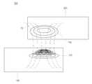
본 발명에 따른 무접점 충전 시스템은 도 1을 참조하여 간략하게 설명하기로 한다. 도 1은 본 발명의 일 실시예에 따른 무접점 충전 시스템을 간략하게 나타낸 예시도이다.The contactless charging system according to the present invention will be briefly described with reference to FIG. 1. 1 is an exemplary view briefly showing a contactless charging system according to an embodiment of the present invention.
도 1을 참조하면, 무접점 충전 시스템(300)은 무접점 충전 장치(100) 및 무접점 충전 배터리 장치(200)를 포함한다.Referring to FIG. 1, the
무접점 충전 장치(100)는 외부 전원(50)으로부터 전기 에너지를 공급받아 무접점 충전 배터리 장치(200)로 공급할 전력을 생성한다. 여기서, 외부 전원(50)은 가정용의 상용 교류 전원(예를 들어, 110V ~ 220V)이 바람직하며, 다른 DC 전원도 사용할 수 있다. 또한, 무접점 충전 장치(100)는 무접점 충전 배터리 장치(200)와 접촉이 용이하도록 무접점 충전 배터리 장치(200)와 접촉하는 면이 평평하게 형성되는 것이 바람직하다. 무접점 충전 장치(100)는 도 2를 참조하여 상세하게 설명하기로 한다.The
무접점 충전 배터리 장치(200)는 무접점 충전 장치(100)의 1차 코일 유 닛(170)을 이용하여 전력을 공급받는다. 즉, 무접점 충전 배터리 장치(200)의 2차 코일 유닛(240)은 1차 코일 유닛(170)과 유기적으로 결합되며 1차 코일 유닛(170)의 자계(Magnetic field, 70)에 의해 유도 기전력을 생성한다. 무접점 충전 배터리 장치(200)는 유도 기전력을 이용하여 배터리(270)를 충전한다.The contactless
무접점 충전 배터리 장치(200)는 배터리(270)를 이용하여 전원을 공급받는 장치이면 그 종류는 무관하다. 예를 들어, 무접점 충전 배터리 장치(200)는 통신 기능이 포함될 수 있는 이동 통신 단말, 데스크탑, 노트북, 넷북과 같은 컴퓨터, PDA(personal digital assistants), MP3(MPEG Audio Layer-3), PMP(portable multimedia player)와 같이 음원, 정지영상 및 동영상을 출력하는 장치, 디지털 전자 사전 등이 될 수 있다. 여기서, 이동 통신 단말은 PDC(Personal Digital Cellular), PCS(Personal Communication Service), PHS(Personal Handyphone System), CDMA△2000(1X, 3X)폰, WCDMA(Wideband CDMA)폰, 듀얼 밴드/듀얼 모드(Dual Band/Dual Mode)폰, GSM(Global Standard for Mobile)폰, MBS(Mobile Broadband System)폰, DMB(Digital Multimedia Broadcasting)폰 및 스마트(Smart) 폰과 같은 통신 기능이 포함될 수 있는 장치일 수 있다.The contactless
무접점 충전 배터리 장치(200)는 도 2를 참조하여 보다 구체적으로 설명하기로 한다.The contactless
본 발명에 따른 무접점 충전 시스템(300)은 도 2를 참조하여 구체적으로 설명하기로 한다. 도 2는 도 1에 나타낸 무접점 충전 시스템(300)을 상세하게 나타낸 블록도이다.The
도 2를 참조하면, 무접점 충전 시스템(300)은 무접점 충전 장치(100) 및 무접점 충전 배터리 장치(200)를 포함한다.Referring to FIG. 2, the
무접점 충전 장치(100)는 수신 유닛(110), 충전 제어 유닛(120), 제 1정류기(130), 전력 분배 유닛(140), 코일 구동 유닛(150) 및 1차 코일 유닛(170)을 포함한다.The
수신 유닛(110)은 무접점 충전 배터리 장치(200)로부터 충전 전력 데이터를 수신한다. 이러한, 수신 유닛(110)은 무선 주파수(radio frequency : RF)통신, 지그비(zigbee)와 같은 무선 통신 방식을 통해 무접점 충전 배터리 장치(200)로부터 충전 전력 데이터를 수신할 수 있다. 또한, 수신 유닛(110)은 무접점 충전 배터리 장치(200)로부터 배터리(270)의 상태를 포함하는 배터리 데이터를 수신할 수 있다.The receiving
충전 제어 유닛(120)은 무접점 충전 배터리 장치(200)에 대응되는 충전 전력을 결정한다. 즉, 충전 제어 유닛(120)은 수신 유닛(110)을 통해 무접점 충전 배터리 장치(200)로부터 수신한 충전 전력 데이터를 이용하여 무접점 충전 배터리 장치(200)에 대응되는 충전 전력을 결정한다. 여기서, 충전 전력은 무접점 충전 배터리 장치(200)의 배터리(270)를 충전하기 위해 필요한 전력이다.The charging
제 1정류기(130)는 외부 전원(50)인 상용 교류 전원으로부터 제공된 교류 전력을 직류 전력인 구동 전력으로 정류시키다. 여기서, 구동 전력은 코일을 구동시키기 위한 전력이다.The
전력 분배 유닛(140)은 무접점 충전 배터리 장치(200)에 따라 구동할 코일을 결정한다. 다시 말하면, 전력 분배 유닛(140)은 충전 제어 유닛(120)에서 결정한 충전 전력에 대응되도록 1차 코일 유닛(170)에서 코일을 결정한다. 이때, 전력 분배 유닛(140)은 충전 전력에 대응되도록 코일을 결정하기 위해 하나 이상을 선택할 수 있다. 이렇게 무접점 충전 배터리 장치(200)에 대응되도록 코일을 결정하기 때문에 하나의 무접점 충전 장치(100)를 이용하여 충전 전력이 다른 무접점 충전 배터리 장치(200)를 충전할 수 있다.The
전력 분배 유닛(140)은 제 1정류기(130)와 코일 구동 유닛(150) 사이에 배치하며 구동 전력을 무접점 충전 배터리 장치(200)에 대응되도록 결정한 하나 이상의 코일(181, 183, 187, 189 : 이하 180으로 통칭함)에 대응되는 하나 이상의 코일 구동 회로(161, 163, 167, 169 : 이하 160으로 통칭함)로 분배한다.The
코일 구동 유닛(150)은 복수개의 코일 구동 회로(160)를 포함한다. 복수개의 코일 구동 회로(160)는 1차 코일 유닛(170)의 복수개의 코일(180)과 대응된다. 즉, 복수개의 코일 구동 회로(160) 각각은 복수개의 코일(180) 각각과 일대일로 대응된다. 코일 구동 유닛(150) 중 구동 전력을 분배받은 코일 구동 회로(160)는 구동 전력을 이용하여 코일(180)을 구동시킨다.The
1차 코일 유닛(170)은 복수개의 코일(180)을 포함한다. 1차 코일 유닛(170)은 코일 구동 유닛(150)에 의해 구동되며 2차 코일 유닛(240)과 접촉하면 자기장을 생성한다. 여기서, 자기장은 1차 코일 유닛(170)에서 생성되어 2차 코일 유닛(240)으로 전달되는 전력이다. 복수개의 코일(180) 각각은 코일선(188)의 감긴 횟수에 따라 동일한 크기의 자기장이 발생하거나 서로 상이한 크기의 자기장을 발생한다. 즉, 1차 코일 유닛(170)은 복수개의 코일(180) 모두 동일하게 코일선(188)이 감겨있으면 제 1번째 코일(181)에서 제 n+1번째 코일(188)로 갈수록 점차적으로 큰 자기장이 발생한다. 그리고, 1차 코일 유닛(170)은 제 1번째 코일(181)의 코일선(188)이 감긴 횟수 보다 제 2번째 코일(183)의 코일선(188)이 감긴 횟수가 작으면 제 1번째 코일(181)과 제 2번째 코일(183)에서 발생하는 자기장의 크기가 동일할 수도 있다. 1차 코일 유닛(170)은 도 3 내지 도 5를 참조하여 상세하게 설명하기로 한다.The
무접점 충전 배터리 장치(200)는 송신 유닛(210), 배터리 제어 유닛(220), 충전 조절 유닛(230), 2차 코일 유닛(240), 제 2정류기(250), 정전압/정전류 유닛(260) 및 배터리(270)를 포함한다.The contactless
송신 유닛(210)은 무접점 충전 장치(100)로 충전 전력 데이터를 전송한다. 송신 유닛(210)은 무선 주파수(radio frequency : RF)통신, 지그비(zigbee)와 같은 무선 통신 방식을 통해 무접점 충전 장치(100)로 충전 전력 데이터를 전송할 수 있다. 그리고, 송신 유닛(210)은 배터리 제어 유닛(220)에서 생성한 배터리 데이터를 무접점 충전 장치(100)로 전송할 수 있다.The transmitting
배터리 제어 유닛(220)은 무접점 충전 장치(100)로 전송하기 위해 배터리(270)를 충전할 수 있는 전력을 판단하여 충전 전력 데이터를 생성한다. 배터리 제어 유닛(220)은 충전 전력 데이터를 무접점 충전 장치(100)로 전송하기 위해 송신 유닛(210)을 제어한다.The
한편, 배터리 제어 유닛(220)은 충전 조절 유닛(230)으로부터 제공받은 배터 리(270)의 초기 상태 정보 및 상태 변화 정보를 판단하여 배터리 데이터를 생성할 수 있다. 배터리 제어 유닛(220)은 배터리 데이터를 무접점 충전 장치(100)로 전송하기 위해 송신 유닛(210)을 제어한다.Meanwhile, the
충전 조절 유닛(230)은 배터리(270)와 연결되며 배터리(270)의 초기 상태를 판단하여 초기 상태 정보를 생성하고, 배터리(270)의 변화하는 상태를 판단하여 상태 변화 정보를 생성한다. 충전 조절 유닛(230)은 배터리(270)의 상태를 판단하여 생성한 초기 상태 정보 상태 변화 정보를 배터리 제어 유닛(220)으로 제공한다.The charging
2차 코일 유닛(240)은 무접점 충전 장치(100)의 1차 코일 유닛(170)과 자기적으로 결합되어 유도 기전력을 발생시킨다. 1차 코일 유닛(170)에서 발생시킨 자기장이 교류 전력이므로 유도 기전력도 교류 전력이다.The
제 2정류기(250)는 2차 코일 유닛(240)의 출력 부분에 연결된다. 그리고, 제 2정류기(250)는 2차 코일 유닛(240)에 의해 발생된 유도 기전력의 교류 전력을 직류 전력으로 정류시킨다.The
정전압/정전류 유닛(260)은 제 2정류기(250)에서 정류한 직류 전력을 이용하여 배터리(270)에 충전할 정전압과 정전류를 생성한다. 즉, 초기에 배터리(270)를 충전할 경우에는 정전류를 유지하다가 배터리(270)의 충전이 포화 상태일 경우에는 정전압으로 전환한다.The constant voltage / constant
배터리(270)는 무접점 충전 배터리 장치(200)에 전원을 공급한다. 배터리(270)는 정전압/정전류 유닛(260)에서 생성한 정전압과 정전류를 이용하여 충전된다. 배터리(270)는 재충전이 가능한 전지셀로 이루어지는 것이 바람직하며 리튬 이온(Lithium ion) 전지나 리튬 폴리머(Lithium polymer) 전지 등으로 이루어질 수 있다.The
본 발명에 따른 1차 코일 유닛(170)은 도 3 내지 도 5를 참조하여 상세하게 설명하기로 한다. 도 3은 본 발명의 일 실시예에 따른 무접점 충전 장치(100)의 1차 코일 유닛(170)을 나타낸 예시도이고, 도 4는 본 발명의 다른 실시예에 따른 무접점 충전 장치(100)의 1차 코일 유닛(170)을 나타낸 예시도이고, 도 5는 본 발명의 또 다른 실시예에 따른 무접점 충전 장치(100)의 1차 코일 유닛(170)을 나타낸 예시도이다.The
1차 코일 유닛(170)은 도 3에 도시된 바와 같이 복수개의 코일(180)로 형성된다. 이때, 복수개의 코일(180) 각각은 원형의 형태로 형성되며 적어도 한번 이상 코일선(188 : 도 2참조)이 감겨서 형성된다. 예를 들어, 복수개의 코일(180) 각각은 코일선(188)이 4번 감겨서 형성될 수 있다. 여기서는 코일선(188)이 동일하게 감겨서 형성되지만 이에 한정되지 않고 복수개의 코일(180) 각각 마다 코일선(188)이 감긴 횟수가 다르게 형성될 수도 있다.The
1차 코일 유닛(170)은 서로 다른 중공부(182, 184, 194, 196, 198 : 이하 190으로 통칭함)의 크기를 갖는 복수개의 코일(180)를 포함한다. 여기서, 중공부(190)는 코일(180)에 의해 형성되는 구멍일 수 있다. 1차 코일 유닛(170)은 복수개의 코일(180) 중 최외곽 코일의 내측에 점차적으로 중공부(190)의 크기가 작아지는 복수개의 코일(180)을 배치한다. 이때, 최외곽 코일은 복수개의 코일 중 가장 외측에 배치하는 코일이며, 예를 들어 제 5번째 코일(199)일 수 있다. 즉, 1차 코일 유닛(170)은 제 5번째 코일(199)의 중공부(198) 내측에 점차적으로 중공부(190)의 크기가 작아지는 제 4번째 코일(197) 내지 제 1번째 코일(181)이 배치된다.The
1차 코일 유닛(170)의 제 2번째 코일(183)은 제 1번째 코일(181)의 외곽을 둘러싸도록 형성되며, 복수개의 코일(180)은 서로 이격되어 형성된다. 즉, 1차 코일 유닛(170)은 제 1중공부(182)의 반경이 제일 작은 제 1번째 코일(181)이 가장 내측에 형성되며 그 다음으로 제 1번째 코일(181)의 외측에 제 2번째 코일(183)이 형성된다. 그리고, 1차 코일 유닛(170)은 제 2번째 코일(183)의 외곽에 순차적으로 제 3번째 코일(195)과 제 4번째 코일(197)이 형성되며, 제 5중공부(198)의 반경이 제일 큰 제 5번째 코일(199)이 가장 외측에 형성된다. 이렇게 코일(180) 속에 코일(180)이 형성되는 이유는 코일(180) 간의 간섭을 방지하기 위함이다.The
1차 코일 유닛(170)은 서로 상이한 크기의 자기장을 발생한다. 즉, 제 2번째 코일(183)은 제 1번째 코일(181)보다 큰 자기장을 발생한다. 이에 따라, 가장 외측에 형성된 제 5번째 코일(199)은 가장 큰 자기장을 발생한다. 또한, 1차 코일 유닛(170)은 서로 상이한 크기의 자기장을 발생하기 위해 복수개의 코일(180) 각각마다 높이가 다르게 형성할 수도 있다.The
한편, 도 3에서는 도시되어 있지 않지만 1차 코일 유닛(170)은 코일선(188 : 도 2참조)이 감긴 횟수를 다르게 하여 중공부(190)의 크기가 상이해도 동일한 크기의 자기장을 발생할 수 있다. 예를 들어, 제 1번째 코일(181)은 코일선(188)을 4번 감고 제 2번째 코일(183)은 코일선(188)을 2번 감으면, 제 1번째 코일(181)에서는 2W의 자기장을 발생하고 제 2번째 코일(183)에서는 2W의 자기장을 발생할 수 있다.Meanwhile, although not shown in FIG. 3, the
한편, 1차 코일 유닛(170)은 도 4에 도시된 바와 같이 원형으로 형성되며 중공부(182, 184, 194, 196, 198 : 이하 190으로 통칭함)의 크기가 상이한 복수개의 코일을 포함한다. 그리고, 1차 코일 유닛(170)은 복수개의 코일이 무게 중심이 동일하며 외측으로 갈수록 중공부(190)의 반지름이 커진다. 즉, 1차 코일 유닛(170)은 제 2번째 코일(183)의 중공부(184) 반지름 보다 제 1번째 코일(181)의 중공부(181) 반지름이 크며, 제 5번째 코일(199)의 중공부(198) 반지름보다 제 4번째 코일(197)의 중공부(196) 반지름이 크다.On the other hand, the
또한, 1차 코일 유닛(170)은 도 5에 도시된 바와 같이 사각형으로 형성된 복수개의 코일을 포함한다. 이때, 복수개의 코일(180)은 무게 중심이 동일하며 제 1번째 코일(181)에서 제 5번째 코일(199)로 갈수록 중공부(182, 184, 194, 196, 198 : 이하 190으로 통칭함)의 크기가 커진다. 즉, 1차 코일 유닛(170)은 제 1번째 코일(181)에서 제 5번째 코일(199)로 갈수록 중공부(190)의 대각선 길이가 커진다. 도 5에서는 도시하지 않았지만 무게 중심이 동일하지 않은 복수개의 코일(180)이 사각형으로 형성될 수도 있다.In addition, the
도 3 내지 도 5에서는 1차 코일 유닛(170)의 복수개의 코일(180)은 원 및 사각형의 형태에 대해서만 예를 들어 설명하였지만 이에 한정되지 않고 코일이 감아서 형성할 수 있는 형태이면 무관하게 형성될 수 있다. 예를 들어, 코일(180)의 중공부(190)는 삼각형, 오각형, 별형 등을 포함하는 다각형 및 타원형 등과 같이 단면적을 높일 수 있는 모든 형상으로 형성할 수 있다.In FIGS. 3 to 5, the plurality of coils 180 of the
도 6은 본 발명의 일 실시예에 따른 무접점 충전 방법을 간략하게 나타낸 순서도이다.Figure 6 is a flow chart briefly showing a contactless charging method according to an embodiment of the present invention.
도 6을 참조하면, 무접점 충전 장치(100)에 무접점 충전 배터리 장치(200)가 접촉한다(S610). 즉, 무접점 충전 배터리 장치(200)의 배터리(270)를 충전하기 위해 무접점 충전 장치(100)에 접속한다. 이때, 무접점 충전 배터리 장치(200)의 2차 코일 유닛(240)과 무접점 충전 장치(100)의 1차 코일 유닛(170)은 마주보고 형성되는 것이 바람직하다.Referring to FIG. 6, the contactless charging
무접점 충전 장치(100)는 무접점 충전 배터리 장치(200)에 대응되는 코일(180)을 결정한다(S620). 무접점 충전 장치(100)는 무접점 충전 배터리 장치(200)로부터 수신한 충전 전력 데이터를 이용하여 무접점 충전 배터리 장치(200)에 대응되는 충전 전력을 판단한다. 그리고, 무접점 충전 장치(100)는 1차 코일 유닛(170)의 복수개의 코일(180)에서 충전 전력에 대응되는 코일(180)을 결정한다. 이때, 무접점 충전 장치(100)는 하나 이상의 코일(180)을 결정할 수 있다.The
무접점 충전 배터리 장치(200)는 무접점 충전 장치(100)에 의해 유도 기전력을 발생한다(S630). 구체적으로, 무접점 충전 배터리 장치(200)의 2차 코일 유닛(240)은 1차 코일 유닛(170) 중 충전 전력에 대응되는 코일(180)에서 발생한 자기장에 의해 유도 기전력을 발생한다.The contactless
무접점 충전 배터리 장치(200)는 배터리(270)를 충전한다(S640). 무접점 충전 배터리 장치(200)는 2차 코일 유닛(240)에서 생성한 유도 기전력을 이용하여 배 터리(270)를 충전한다. 이에 따라, 무접점 충전 배터리 장치(200)는 무접점 충전 장치(100)를 이용하여 배터리(270)를 충전할 수 있으므로 배터리(270) 및 충전 장치의 접촉 단자가 수분에 의해 부식되거나 마모되어 발생하는 문제를 해결할 수 있다.The contactless
도 7은 본 발명의 일 실시예에 따른 무접점 충전 장치(100)가 무접점 충전 방법을 나타낸 순서도이다.7 is a flowchart illustrating a contactless charging method of the
도 7을 참조하면, 무접점 충전 장치(100)는 충전 전력 데이터를 이용하여 충전 전력을 결정한다(S710). 구체적으로, 무접점 충전 장치(100)에 무접점 충전 배터리 장치(200)가 접촉되면 무접점 충전 장치(100)의 수신 유닛(110)은 무접점 충전 배터리 장치(200)로부터 충전 전력 데이터를 수신한다. 충전 제어 유닛(120)은 수신 유닛(110)으로부터 제공받은 충전 전력 데이터를 이용하여 무접점 충전 배터리 장치(200)에서 충전할 충전 전력을 결정한다.Referring to FIG. 7, the
무접점 충전 장치(100)는 충전 전력에 대응되는 하나 이상의 코일(180)을 결정한다(S720). 다시 말하면, 무접점 충전 장치(100)의 전력 분배 유닛(140)은 충전 제어 유닛(120)으로 충전 전력을 제공받는다. 그리고, 전력 분배 유닛(140)은 1차 코일 유닛(170)에 포함된 복수개의 코일(180)에서 충전 전력에 대응되는 코일(180)을 결정한다. 예를 들어, 제 1번째 코일(181)이 5W, 제 2번째 코일(183)이 10W, 제 3번째 코일이 15W의 자기장을 발생시키고 충전 제어 유닛(120)에서 충전 전력 데이터를 이용하여 5W의 충전 전력을 결정하면, 전력 분배 유닛(140)은 5W의 충전 전력 을 이용하여 5W에 해당하는 코일을 결정한다. 즉, 전력 분배 유닛(140)은 제 1번째 코일을 결정한다.The
한편, 전력 분배 유닛(140)은 하나 이상의 코일을 결정할 수 있다. 예를 들어, 제 1번째 코일(181)이 2W, 제 2번째 코일(183)이 3W, 제 3번째 코일이 6W의 자기장을 발생시키고 충전 제어 유닛(120)에서 충전 전력 데이터를 이용하여 5W의 충전 전력을 결정하면, 전력 분배 유닛(140)은 5W의 충전 전력을 이용하여 5W에 해당하는 코일을 결정한다. 즉, 전력 분배 유닛(140)은 제 1번째 코일(181) 및 제 2번째 코일(183)을 결정한다. 또한, 제 1번째 코일(181)이 2W, 제 2번째 코일(183)이 2W, 제 3번째 코일이 6W의 자기장을 발생시키고 충전 제어 유닛(120)에서 충전 전력 데이터를 이용하여 4W의 충전 전력을 결정하면, 전력 분배 유닛(140)은 4W의 충전 전력을 이용하여 4W에 해당하는 코일을 결정한다. 즉, 전력 분배 유닛(140)은 제 1번째 코일(181) 및 제 2번째 코일(183)을 결정한다.Meanwhile, the
무접점 충전 장치(100)는 결정한 코일(180)에 대응되는 코일 구동 회로(160)로 구동 전력을 분배한다(S730). 구체적으로, 무접점 충전 장치(100)의 정류기는 외부 전원(50)인 상용 교류 전원으로부터 제공된 교류 전력을 직류 전력인 구동 전력으로 정류시키고, 이러한 구동 전력을 전력 분배 유닛(140)으로 제공한다. 그리고, 전력 분배 유닛(140)은 결정한 코일(180)에 대응되는 코일 구동 회로(160)로 코일(180)을 구동시키기 위해 구동 전력을 분배한다. 예를 들어, 전력 분배 유닛(140)은 충전 전력에 대응되도록 자기장을 발생시키기 위해 제 1코일 구동 회로(161)과 제 2코일 구동 회로(163)으로 구동 전력을 분배한다.The
여기서는 교류 전력을 직류 전력으로 정류시키는 단계를 구동할 코일(180)을 결정한 후로 예를 들어 설명하였지만 이에 한정되지 않고 전력 분배 유닛(140)이 구동 전력을 코일 구동 유닛(150)으로 분배하기 전이면 그 순서는 무관하다.In this example, after the coil 180 to drive the step of rectifying the AC power to the DC power is determined. For example, the present invention is not limited thereto, and the
무접점 충전 장치(100)는 구동 전력을 이용하여 코일(180)을 구동시킨다(S740). 즉, 무접점 충전 장치(100)의 코일 구동 유닛(150) 중 구동 전력을 분배받은 코일 구동 회로(160)는 구동 전력을 이용하여 코일(180)을 구동시킨다. 예를 들어, 구동 전력을 분배받은 제 1코일 구동 회로(161)와 제 2코일 구동 회로(163) 각각은 제 1번째 코일(181), 제 2번째 코일(183) 각각을 구동시킨다.The
무접점 충전 장치(100)는 자기장을 생성한다(S750). 다시 말하면, 무접점 충전 장치(100)의 1차 코일 유닛(170)은 무접점 충전 배터리 장치(200)의 2차 코일 유닛(240)과 유기적으로 결합되어 자기장을 생성한다. 이에 따라, 무접점 충전 장치(100)는 크기가 다른 자기장을 발생시키는 복수개의 코일(180)을 포함하므로 충전 전력이 다른 무접점 충전 배터리 장치(200)를 충전할 수 있으며, 무접점 충전 배터리 장치(200)에 따른 충전 전력에 대응되는 코일(180)만 구동시키므로 소비 전력을 효율적으로 사용할 수 있다.The
도 8은 본 발명의 일 실시예에 따른 무접점 충전 배터리 장치(200)가 무접점 충전 방법을 나타낸 순서도이다.8 is a flowchart illustrating a contactless charging method of the contactless
도 8을 참조하면, 무접점 충전 배터리 장치(200)는 충전 전력 데이터를 생성한다(S810). 구체적으로, 무접점 충전 배터리 장치(200)의 배터리 제어 유닛(220) 은 배터리(270)를 충전하기 위한 충전 전력을 판단한다. 그리고, 배터리 제어 유닛(220)은 충전 전력을 이용하여 무접점 충전 장치(100)에 전송할 충전 전력 데이터를 생성한다. 배터리 제어 유닛(220)은 충전 전력 데이터를 송신 유닛(210)을 통해 무접점 충전 장치(100)로 전송하도록 제어한다.Referring to FIG. 8, the contactless
무접점 충전 배터리 장치(200)는 무접점 충전 장치(100)에 의해 유도 기전력을 발생한다(S820). 즉, 무접점 충전 배터리 장치(200)의 2차 코일 유닛(240)은 무접점 충전 장치(100)의 1차 코일 유닛(170)과 자기적으로 결합하며 1차 코일 유닛(170)에 의해 생성된 자기장에 의해 유도 기전력을 발생한다. 이때, 1차 코일 유닛(170)은 무접점 충전 배터리 장치(200)의 충전 전력에 대응되는 코일(180)이며, 배터리(270)에서 충전할 때 필요한 충전 전력에 대응되는 자기장을 발생한다.The contactless
무접점 충전 배터리 장치(200)는 유도 기전력을 직류 전력으로 정류시킨다(S830). 다시 말하면, 무접점 충전 배터리 장치(200)의 제 1정류기(130)는 2차 코일 유닛(240)에서 생성한 교류 전력의 유도 기전력을 일전한 레벨의 직류 전력으로 정류시킨다.The contactless
무접점 충전 배터리 장치(200)는 직류 전력을 이용하여 정전압/정전류를 생성한다(S840). 구체적으로, 무접점 충전 배터리 장치(200)의 정전압/정전류 유닛(260)은 제 1정류기(130)에서 정류시킨 직류 전력을 이용하여 배터리(270)에 충전할 정전압 및 정전류를 생성한다.The contactless
무접점 충전 배터리 장치(200)는 정전압/정전류를 이용하여 배터리(270)를 충전한다(S850). 즉, 무접점 충전 배터리 장치(200)의 배터리(270)는 정전압/정전 류 유닛(260)에서 생성한 정전류를 이용하여 충전되고, 충전 전압이 포화상태가 되면 정전압으로 전환된다.The contactless
상기에서는 본 발명의 바람직한 실시예를 참조하여 설명하였지만, 해당 기술 분야에서 통상의 지식을 가진 자라면 하기의 특허 청구의 범위에 기재된 본 발명의 사상 및 영역으로부터 벗어나지 않는 범위 내에서 본 발명을 다양하게 수정 및 변경시킬 수 있음을 이해할 수 있을 것이다.It will be apparent to those skilled in the art that various modifications and variations can be made in the present invention without departing from the spirit or scope of the invention as defined in the appended claims. It will be understood that the invention may be varied and varied without departing from the scope of the invention.
도 1은 본 발명의 일 실시예에 따른 무접점 충전 시스템을 간략하게 나타낸 예시도이다.1 is an exemplary view briefly showing a contactless charging system according to an embodiment of the present invention.
도 2는 도 1에 나타낸 무접점 충전 시스템을 상세하게 나타낸 블록도이다.FIG. 2 is a detailed block diagram of the contactless charging system shown in FIG. 1.
도 3은 본 발명의 일 실시예에 따른 무접점 충전 장치의 1차 코일 유닛을 나타낸 예시도이다.3 is an exemplary view showing a primary coil unit of a contactless charging device according to an embodiment of the present invention.
도 4는 본 발명의 다른 실시예에 따른 무접점 충전 장치의 1차 코일 유닛을 나타낸 예시도이다.4 is an exemplary view showing a primary coil unit of a contactless charging device according to another embodiment of the present invention.
도 5는 본 발명의 또 다른 실시예에 따른 무접점 충전 장치의 1차 코일 유닛을 나타낸 예시도이다.5 is an exemplary view showing a primary coil unit of a contactless charging device according to another embodiment of the present invention.
도 6은 본 발명의 일 실시예에 따른 무접점 충전 방법을 간략하게 나타낸 순서도이다.Figure 6 is a flow chart briefly showing a contactless charging method according to an embodiment of the present invention.
도 7은 본 발명의 일 실시예에 따른 무접점 충전 장치가 무접점 충전 방법을 나타낸 순서도이다.7 is a flowchart illustrating a contactless charging method of the contactless charging device according to an embodiment of the present invention.
도 8은 본 발명의 일 실시예에 따른 무접점 충전 배터리 장치가 무접점 충전 방법을 나타낸 순서도이다.8 is a flowchart illustrating a contactless charging method of a contactless rechargeable battery device according to an exemplary embodiment of the present invention.
<도면의 주요 부분에 대한 부호의 설명><Explanation of symbols for the main parts of the drawings>
100 : 무접점 충전 장치100: contactless charging device
120 : 충전 제어 유닛120: charge control unit
130 : 제 1정류기130: first rectifier
140 : 전력 분배 유닛140: power distribution unit
150 : 코일 구동 유닛150: coil drive unit
170 : 1차 코일 유닛170: primary coil unit
200 : 무접점 충전 배터리 장치200: contactless rechargeable battery unit
220 : 배터리 제어 유닛220: battery control unit
230 : 충전 조절 유닛230: charge control unit
240 : 2차 코일 유닛240: secondary coil unit
250 : 제 2정류기250: second rectifier
260 : 정전압/정전류 유닛260 constant voltage / constant current unit
270 : 배터리270 battery
300 : 무접점 충전 시스템300: solid state charging system
Claims (18)
Translated fromKoreanPriority Applications (4)
| Application Number | Priority Date | Filing Date | Title |
|---|---|---|---|
| KR1020090086999AKR101136532B1 (en) | 2009-09-15 | 2009-09-15 | Contactless charging device, contactless charging battery device and contactless charging system comprising the same |
| JP2012529647AJP2013505000A (en) | 2009-09-15 | 2010-01-15 | Contactless charging device, contactless charging battery device and contactless charging system including the same |
| PCT/KR2010/000278WO2011034264A1 (en) | 2009-09-15 | 2010-01-15 | Contactless charging apparatus, contactless charging battery apparatus, and contactless charging system including same |
| US13/496,136US20120169279A1 (en) | 2009-09-15 | 2010-01-15 | Contactless charging apparatus, contactless charging battery apparatus, and contactless charging system including same |
Applications Claiming Priority (1)
| Application Number | Priority Date | Filing Date | Title |
|---|---|---|---|
| KR1020090086999AKR101136532B1 (en) | 2009-09-15 | 2009-09-15 | Contactless charging device, contactless charging battery device and contactless charging system comprising the same |
Publications (2)
| Publication Number | Publication Date |
|---|---|
| KR20110029358A KR20110029358A (en) | 2011-03-23 |
| KR101136532B1true KR101136532B1 (en) | 2012-04-17 |
Family
ID=43758841
Family Applications (1)
| Application Number | Title | Priority Date | Filing Date |
|---|---|---|---|
| KR1020090086999AExpired - Fee RelatedKR101136532B1 (en) | 2009-09-15 | 2009-09-15 | Contactless charging device, contactless charging battery device and contactless charging system comprising the same |
Country Status (4)
| Country | Link |
|---|---|
| US (1) | US20120169279A1 (en) |
| JP (1) | JP2013505000A (en) |
| KR (1) | KR101136532B1 (en) |
| WO (1) | WO2011034264A1 (en) |
Cited By (1)
| Publication number | Priority date | Publication date | Assignee | Title |
|---|---|---|---|---|
| KR20160072565A (en)* | 2014-12-15 | 2016-06-23 | 한솔테크닉스(주) | Power hub device of radio charge base |
Families Citing this family (21)
| Publication number | Priority date | Publication date | Assignee | Title |
|---|---|---|---|---|
| KR101228556B1 (en)* | 2010-11-04 | 2013-02-07 | 주식회사 한림포스텍 | Method for controlling to select one in plurality of coils in wirelesee power transmission device, wireless power transmission device thereof and wireless power transmission system thereof |
| US10685780B2 (en) | 2011-03-29 | 2020-06-16 | Sony Corporation | Electric power feed apparatus, electric power feed system, and electronic apparatus |
| JP5968596B2 (en)* | 2011-04-11 | 2016-08-10 | 日東電工株式会社 | Wireless power supply system |
| KR101321436B1 (en)* | 2011-11-08 | 2013-11-04 | 삼성전자주식회사 | Wireless power transmission system, resonator design method for optimal power distribution and resonator in wireless power transmission system |
| EP2824799B1 (en) | 2012-03-06 | 2022-01-05 | Murata Manufacturing Co., Ltd. | Power transmission system |
| US10404075B2 (en)* | 2012-09-28 | 2019-09-03 | Avago Technologies International Sales Pte. Limited | Power receiving device having device discovery and power transfer capabilities |
| US9496746B2 (en)* | 2013-05-15 | 2016-11-15 | The Regents Of The University Of Michigan | Wireless power transmission for battery charging |
| CN104659846A (en)* | 2013-11-20 | 2015-05-27 | 英业达科技有限公司 | Wireless device and wireless charging method |
| CN105024408B (en)* | 2014-04-15 | 2017-04-12 | 侨威科技股份有限公司 | Series wireless charging system and charging method thereof |
| WO2016076480A1 (en)* | 2014-11-13 | 2016-05-19 | 엘지전자 주식회사 | Wireless power transmission apparatus, wireless power reception apparatus, and wireless charging system |
| KR20160057278A (en)* | 2014-11-13 | 2016-05-23 | 엘지전자 주식회사 | Wireless power transmitter,wireless power receiver, and wireless charging system |
| US9944190B2 (en)* | 2015-03-07 | 2018-04-17 | Hyundai Motor Company | Interoperable EV wireless charging system based on air gap between primary and secondary coils |
| US9991744B2 (en) | 2015-07-03 | 2018-06-05 | Samsung Electro-Mechanics Co., Ltd. | Wireless power receiving device and apparatus including the same |
| US10511191B2 (en)* | 2015-07-09 | 2019-12-17 | Qualcomm Incorporated | Apparatus and methods for wireless power transmitter coil configuration |
| US10483783B2 (en)* | 2015-07-28 | 2019-11-19 | Motorola Solutions, Inc. | System and method for identifying a wirelessly charging battery |
| US11362530B2 (en)* | 2016-03-24 | 2022-06-14 | Intel Corporation | Conical wireless charging station |
| KR101635084B1 (en)* | 2016-03-31 | 2016-06-30 | 주식회사 핀크래프트엔지니어링 | Multi charging device enabled by current and voltage control |
| JPWO2018062117A1 (en)* | 2016-09-28 | 2019-09-05 | 日本電産株式会社 | Non-contact power supply coil unit |
| WO2018144806A1 (en)* | 2017-02-03 | 2018-08-09 | AMI Research & Development, LLC | Electric vehicle charging via rf loops to avoid need for precise alignment with wireless charging equipment |
| CN108923545B (en) | 2018-07-10 | 2020-01-17 | 维沃移动通信有限公司 | An electronic device, wireless charging device and wireless charging method |
| CN115244819A (en)* | 2020-01-06 | 2022-10-25 | 艾拉公司 | Swinging coil in multi-coil wireless charger |
Citations (2)
| Publication number | Priority date | Publication date | Assignee | Title |
|---|---|---|---|---|
| KR100792311B1 (en)* | 2005-07-30 | 2008-01-07 | 엘에스전선 주식회사 | Charging power supply, charging device, battery unit, contactless charging system and contactless charging method |
| KR20080032519A (en)* | 2006-10-10 | 2008-04-15 | 엘에스전선 주식회사 | Charging power supply, battery unit, solid state charging system and charging method |
Family Cites Families (10)
| Publication number | Priority date | Publication date | Assignee | Title |
|---|---|---|---|---|
| KR20010048695A (en)* | 1999-11-29 | 2001-06-15 | 장긍덕 | Electro-magnetic type non-contact chargable battery pack and charger |
| KR20030072999A (en)* | 2002-03-08 | 2003-09-19 | 이강용 | The Non Contact Charge System of Variable Chargeable Battery |
| US8183827B2 (en)* | 2003-01-28 | 2012-05-22 | Hewlett-Packard Development Company, L.P. | Adaptive charger system and method |
| JP4156537B2 (en)* | 2004-01-21 | 2008-09-24 | 理想科学工業株式会社 | Power supply device |
| KR100819604B1 (en)* | 2005-07-27 | 2008-04-03 | 엘에스전선 주식회사 | Wireless Charger Decreased in Variation of Charging Efficiency |
| KR100853889B1 (en)* | 2005-07-29 | 2008-08-25 | 엘에스전선 주식회사 | Contactless rechargeable batteries and chargers, battery charging sets comprising them, and charging control methods |
| KR100792308B1 (en)* | 2006-01-31 | 2008-01-07 | 엘에스전선 주식회사 | Solid state charging device with coil array, solid state charging system and charging method |
| KR100836631B1 (en)* | 2006-12-11 | 2008-06-10 | 주식회사 한림포스텍 | Multi contactless charging system |
| JP4930093B2 (en)* | 2007-02-21 | 2012-05-09 | セイコーエプソン株式会社 | Power transmission control device, power reception control device, non-contact power transmission system, power transmission device, power reception device, and electronic equipment |
| JP4893374B2 (en)* | 2007-03-05 | 2012-03-07 | パナソニック電工株式会社 | Interrogator, wireless authentication system |
- 2009
- 2009-09-15KRKR1020090086999Apatent/KR101136532B1/ennot_activeExpired - Fee Related
- 2010
- 2010-01-15JPJP2012529647Apatent/JP2013505000A/enactivePending
- 2010-01-15USUS13/496,136patent/US20120169279A1/ennot_activeAbandoned
- 2010-01-15WOPCT/KR2010/000278patent/WO2011034264A1/enactiveApplication Filing
Patent Citations (2)
| Publication number | Priority date | Publication date | Assignee | Title |
|---|---|---|---|---|
| KR100792311B1 (en)* | 2005-07-30 | 2008-01-07 | 엘에스전선 주식회사 | Charging power supply, charging device, battery unit, contactless charging system and contactless charging method |
| KR20080032519A (en)* | 2006-10-10 | 2008-04-15 | 엘에스전선 주식회사 | Charging power supply, battery unit, solid state charging system and charging method |
Cited By (2)
| Publication number | Priority date | Publication date | Assignee | Title |
|---|---|---|---|---|
| KR20160072565A (en)* | 2014-12-15 | 2016-06-23 | 한솔테크닉스(주) | Power hub device of radio charge base |
| KR101675495B1 (en)* | 2014-12-15 | 2016-11-22 | 한솔테크닉스(주) | Power hub device of radio charge base |
Also Published As
| Publication number | Publication date |
|---|---|
| WO2011034264A1 (en) | 2011-03-24 |
| US20120169279A1 (en) | 2012-07-05 |
| JP2013505000A (en) | 2013-02-07 |
| KR20110029358A (en) | 2011-03-23 |
Similar Documents
| Publication | Publication Date | Title |
|---|---|---|
| KR101136532B1 (en) | Contactless charging device, contactless charging battery device and contactless charging system comprising the same | |
| US10461585B2 (en) | Power-receiving device, wireless power-feeding system including power-receiving device, and wireless communication system including power-receiving device | |
| US20250239889A1 (en) | Apparatus and method for providing compatibility in wireless power transmission system | |
| KR100566220B1 (en) | Solid state battery charger | |
| US7622892B2 (en) | Contactless battery charger | |
| US10523276B2 (en) | Wireless power receiver with multiple receiver coils | |
| CN104620471B (en) | Wireless power transmitter excluding cross-connected wireless power receiver and method for controlling same | |
| US20120295451A1 (en) | Magnetic connecting device | |
| US9425863B2 (en) | Apparatus and method for wirelessly receiving power, and apparatus and method for wirelessly transmitting power | |
| KR20020057469A (en) | A coreless low-profile pcb transformer and contactless battery charger using the pcb transformer | |
| JP2009136133A (en) | Multiple non-contact charging system and control method thereof | |
| US20130099733A1 (en) | Wireless power transmitter and method of controlling the same | |
| CN103326474B (en) | Wireless power receiver and wireless power transmission method | |
| US9680328B2 (en) | Electronic apparatus and feed system | |
| CN102005784A (en) | Wireless charging system | |
| KR102491037B1 (en) | Wireless power reception device and wireless communication method | |
| US9450448B2 (en) | Wireless charging device and electric energy recycling method thereof | |
| US20160099576A1 (en) | Wireless power transmission device | |
| WO2021082907A1 (en) | Wireless charging system, charging cable, electronic device, and wireless charging method therefor | |
| CN108604823A (en) | Magnetic field forming device, for electric installation, power receiving device, by electricity for electric installation and portable equipment | |
| KR101532052B1 (en) | Antenna patch comprising common terminals for wireless charging and nfc communication | |
| KR101712647B1 (en) | Auxiliary battery for wirelessly charging and discharging | |
| KR200473080Y1 (en) | Wireless charging pad using design light | |
| WO2017051821A1 (en) | Power reception/feeding device | |
| CN201478848U (en) | Wireless charging system |
Legal Events
| Date | Code | Title | Description |
|---|---|---|---|
| A201 | Request for examination | ||
| PA0109 | Patent application | St.27 status event code:A-0-1-A10-A12-nap-PA0109 | |
| PA0201 | Request for examination | St.27 status event code:A-1-2-D10-D11-exm-PA0201 | |
| E902 | Notification of reason for refusal | ||
| PE0902 | Notice of grounds for rejection | St.27 status event code:A-1-2-D10-D21-exm-PE0902 | |
| T11-X000 | Administrative time limit extension requested | St.27 status event code:U-3-3-T10-T11-oth-X000 | |
| PG1501 | Laying open of application | St.27 status event code:A-1-1-Q10-Q12-nap-PG1501 | |
| T11-X000 | Administrative time limit extension requested | St.27 status event code:U-3-3-T10-T11-oth-X000 | |
| T11-X000 | Administrative time limit extension requested | St.27 status event code:U-3-3-T10-T11-oth-X000 | |
| T11-X000 | Administrative time limit extension requested | St.27 status event code:U-3-3-T10-T11-oth-X000 | |
| P11-X000 | Amendment of application requested | St.27 status event code:A-2-2-P10-P11-nap-X000 | |
| P13-X000 | Application amended | St.27 status event code:A-2-2-P10-P13-nap-X000 | |
| E701 | Decision to grant or registration of patent right | ||
| PE0701 | Decision of registration | St.27 status event code:A-1-2-D10-D22-exm-PE0701 | |
| GRNT | Written decision to grant | ||
| PR0701 | Registration of establishment | St.27 status event code:A-2-4-F10-F11-exm-PR0701 | |
| PR1002 | Payment of registration fee | St.27 status event code:A-2-2-U10-U11-oth-PR1002 Fee payment year number:1 | |
| PG1601 | Publication of registration | St.27 status event code:A-4-4-Q10-Q13-nap-PG1601 | |
| PN2301 | Change of applicant | St.27 status event code:A-5-5-R10-R13-asn-PN2301 St.27 status event code:A-5-5-R10-R11-asn-PN2301 | |
| PN2301 | Change of applicant | St.27 status event code:A-5-5-R10-R11-asn-PN2301 | |
| PN2301 | Change of applicant | St.27 status event code:A-5-5-R10-R14-asn-PN2301 | |
| P14-X000 | Amendment of ip right document requested | St.27 status event code:A-5-5-P10-P14-nap-X000 | |
| P16-X000 | Ip right document amended | St.27 status event code:A-5-5-P10-P16-nap-X000 | |
| Q16-X000 | A copy of ip right certificate issued | St.27 status event code:A-4-4-Q10-Q16-nap-X000 | |
| PR1001 | Payment of annual fee | St.27 status event code:A-4-4-U10-U11-oth-PR1001 Fee payment year number:4 | |
| FPAY | Annual fee payment | Payment date:20160407 Year of fee payment:5 | |
| PR1001 | Payment of annual fee | St.27 status event code:A-4-4-U10-U11-oth-PR1001 Fee payment year number:5 | |
| FPAY | Annual fee payment | Payment date:20170405 Year of fee payment:6 | |
| PR1001 | Payment of annual fee | St.27 status event code:A-4-4-U10-U11-oth-PR1001 Fee payment year number:6 | |
| FPAY | Annual fee payment | Payment date:20180409 Year of fee payment:7 | |
| PR1001 | Payment of annual fee | St.27 status event code:A-4-4-U10-U11-oth-PR1001 Fee payment year number:7 | |
| P22-X000 | Classification modified | St.27 status event code:A-4-4-P10-P22-nap-X000 | |
| FPAY | Annual fee payment | Payment date:20190306 Year of fee payment:8 | |
| PR1001 | Payment of annual fee | St.27 status event code:A-4-4-U10-U11-oth-PR1001 Fee payment year number:8 | |
| FPAY | Annual fee payment | Payment date:20200221 Year of fee payment:9 | |
| PR1001 | Payment of annual fee | St.27 status event code:A-4-4-U10-U11-oth-PR1001 Fee payment year number:9 | |
| PR1001 | Payment of annual fee | St.27 status event code:A-4-4-U10-U11-oth-PR1001 Fee payment year number:10 | |
| P22-X000 | Classification modified | St.27 status event code:A-4-4-P10-P22-nap-X000 | |
| PR1001 | Payment of annual fee | St.27 status event code:A-4-4-U10-U11-oth-PR1001 Fee payment year number:11 | |
| PR1001 | Payment of annual fee | St.27 status event code:A-4-4-U10-U11-oth-PR1001 Fee payment year number:12 | |
| PC1903 | Unpaid annual fee | St.27 status event code:A-4-4-U10-U13-oth-PC1903 Not in force date:20240407 Payment event data comment text:Termination Category : DEFAULT_OF_REGISTRATION_FEE | |
| PC1903 | Unpaid annual fee | St.27 status event code:N-4-6-H10-H13-oth-PC1903 Ip right cessation event data comment text:Termination Category : DEFAULT_OF_REGISTRATION_FEE Not in force date:20240407 |