KR101136203B1 - Bone plate - Google Patents
Bone plateDownload PDFInfo
- Publication number
- KR101136203B1 KR101136203B1KR1020067007559AKR20067007559AKR101136203B1KR 101136203 B1KR101136203 B1KR 101136203B1KR 1020067007559 AKR1020067007559 AKR 1020067007559AKR 20067007559 AKR20067007559 AKR 20067007559AKR 101136203 B1KR101136203 B1KR 101136203B1
- Authority
- KR
- South Korea
- Prior art keywords
- bone plate
- bone
- hole
- plate according
- holes
- Prior art date
- Legal status (The legal status is an assumption and is not a legal conclusion. Google has not performed a legal analysis and makes no representation as to the accuracy of the status listed.)
- Expired - Fee Related
Links
Images

Classifications
- A—HUMAN NECESSITIES
- A61—MEDICAL OR VETERINARY SCIENCE; HYGIENE
- A61B—DIAGNOSIS; SURGERY; IDENTIFICATION
- A61B17/00—Surgical instruments, devices or methods
- A61B17/56—Surgical instruments or methods for treatment of bones or joints; Devices specially adapted therefor
- A61B17/58—Surgical instruments or methods for treatment of bones or joints; Devices specially adapted therefor for osteosynthesis, e.g. bone plates, screws or setting implements
- A61B17/68—Internal fixation devices, including fasteners and spinal fixators, even if a part thereof projects from the skin
- A61B17/80—Cortical plates, i.e. bone plates; Instruments for holding or positioning cortical plates, or for compressing bones attached to cortical plates
- A—HUMAN NECESSITIES
- A61—MEDICAL OR VETERINARY SCIENCE; HYGIENE
- A61B—DIAGNOSIS; SURGERY; IDENTIFICATION
- A61B17/00—Surgical instruments, devices or methods
- A61B17/56—Surgical instruments or methods for treatment of bones or joints; Devices specially adapted therefor
- A61B17/58—Surgical instruments or methods for treatment of bones or joints; Devices specially adapted therefor for osteosynthesis, e.g. bone plates, screws or setting implements
- A61B17/68—Internal fixation devices, including fasteners and spinal fixators, even if a part thereof projects from the skin
- A61B17/72—Intramedullary devices, e.g. pins or nails
- A61B17/7291—Intramedullary devices, e.g. pins or nails for small bones, e.g. in the foot, ankle, hand or wrist
- A—HUMAN NECESSITIES
- A61—MEDICAL OR VETERINARY SCIENCE; HYGIENE
- A61B—DIAGNOSIS; SURGERY; IDENTIFICATION
- A61B17/00—Surgical instruments, devices or methods
- A61B17/56—Surgical instruments or methods for treatment of bones or joints; Devices specially adapted therefor
- A61B17/58—Surgical instruments or methods for treatment of bones or joints; Devices specially adapted therefor for osteosynthesis, e.g. bone plates, screws or setting implements
- A61B17/68—Internal fixation devices, including fasteners and spinal fixators, even if a part thereof projects from the skin
- A61B17/80—Cortical plates, i.e. bone plates; Instruments for holding or positioning cortical plates, or for compressing bones attached to cortical plates
- A61B17/8052—Cortical plates, i.e. bone plates; Instruments for holding or positioning cortical plates, or for compressing bones attached to cortical plates immobilised relative to screws by interlocking form of the heads and plate holes, e.g. conical or threaded
- A61B17/8057—Cortical plates, i.e. bone plates; Instruments for holding or positioning cortical plates, or for compressing bones attached to cortical plates immobilised relative to screws by interlocking form of the heads and plate holes, e.g. conical or threaded the interlocking form comprising a thread
- A—HUMAN NECESSITIES
- A61—MEDICAL OR VETERINARY SCIENCE; HYGIENE
- A61B—DIAGNOSIS; SURGERY; IDENTIFICATION
- A61B17/00—Surgical instruments, devices or methods
- A61B17/56—Surgical instruments or methods for treatment of bones or joints; Devices specially adapted therefor
- A61B17/58—Surgical instruments or methods for treatment of bones or joints; Devices specially adapted therefor for osteosynthesis, e.g. bone plates, screws or setting implements
- A61B17/68—Internal fixation devices, including fasteners and spinal fixators, even if a part thereof projects from the skin
- A61B17/80—Cortical plates, i.e. bone plates; Instruments for holding or positioning cortical plates, or for compressing bones attached to cortical plates
- A61B17/8061—Cortical plates, i.e. bone plates; Instruments for holding or positioning cortical plates, or for compressing bones attached to cortical plates specially adapted for particular bones
- A—HUMAN NECESSITIES
- A61—MEDICAL OR VETERINARY SCIENCE; HYGIENE
- A61B—DIAGNOSIS; SURGERY; IDENTIFICATION
- A61B17/00—Surgical instruments, devices or methods
- A61B17/00234—Surgical instruments, devices or methods for minimally invasive surgery
- A—HUMAN NECESSITIES
- A61—MEDICAL OR VETERINARY SCIENCE; HYGIENE
- A61B—DIAGNOSIS; SURGERY; IDENTIFICATION
- A61B17/00—Surgical instruments, devices or methods
- A61B17/16—Instruments for performing osteoclasis; Drills or chisels for bones; Trepans
- A61B17/17—Guides or aligning means for drills, mills, pins or wires
- A61B17/1725—Guides or aligning means for drills, mills, pins or wires for applying transverse screws or pins through intramedullary nails or pins
- A—HUMAN NECESSITIES
- A61—MEDICAL OR VETERINARY SCIENCE; HYGIENE
- A61B—DIAGNOSIS; SURGERY; IDENTIFICATION
- A61B17/00—Surgical instruments, devices or methods
- A61B17/56—Surgical instruments or methods for treatment of bones or joints; Devices specially adapted therefor
- A61B17/58—Surgical instruments or methods for treatment of bones or joints; Devices specially adapted therefor for osteosynthesis, e.g. bone plates, screws or setting implements
- A61B17/68—Internal fixation devices, including fasteners and spinal fixators, even if a part thereof projects from the skin
- A61B17/72—Intramedullary devices, e.g. pins or nails
- A61B17/7233—Intramedullary devices, e.g. pins or nails with special means of locking the nail to the bone
- A—HUMAN NECESSITIES
- A61—MEDICAL OR VETERINARY SCIENCE; HYGIENE
- A61B—DIAGNOSIS; SURGERY; IDENTIFICATION
- A61B17/00—Surgical instruments, devices or methods
- A61B17/56—Surgical instruments or methods for treatment of bones or joints; Devices specially adapted therefor
- A61B17/58—Surgical instruments or methods for treatment of bones or joints; Devices specially adapted therefor for osteosynthesis, e.g. bone plates, screws or setting implements
- A61B17/88—Osteosynthesis instruments; Methods or means for implanting or extracting internal or external fixation devices
- A61B17/92—Impactors or extractors, e.g. for removing intramedullary devices
- A61B17/921—Impactors or extractors, e.g. for removing intramedullary devices for intramedullary devices
- A—HUMAN NECESSITIES
- A61—MEDICAL OR VETERINARY SCIENCE; HYGIENE
- A61B—DIAGNOSIS; SURGERY; IDENTIFICATION
- A61B17/00—Surgical instruments, devices or methods
- A61B17/56—Surgical instruments or methods for treatment of bones or joints; Devices specially adapted therefor
- A61B2017/564—Methods for bone or joint treatment
- A61B2017/565—Methods for bone or joint treatment for surgical correction of axial deviation, e.g. hallux valgus or genu valgus
Landscapes
- Health & Medical Sciences (AREA)
- Orthopedic Medicine & Surgery (AREA)
- Surgery (AREA)
- Life Sciences & Earth Sciences (AREA)
- Heart & Thoracic Surgery (AREA)
- Nuclear Medicine, Radiotherapy & Molecular Imaging (AREA)
- Engineering & Computer Science (AREA)
- Biomedical Technology (AREA)
- Medical Informatics (AREA)
- Molecular Biology (AREA)
- Animal Behavior & Ethology (AREA)
- General Health & Medical Sciences (AREA)
- Public Health (AREA)
- Veterinary Medicine (AREA)
- Neurology (AREA)
- Surgical Instruments (AREA)
- Prostheses (AREA)
Abstract
Translated fromKoreanDescription
Translated fromKorean본 발명은 청구항 1의 전제부에서 정의된 뼈플레이트에 관한 것이다.The present invention relates to a bone plate as defined in the preamble of claim 1.
종래의 뼈플레이트는 앞발 절골술(osteotomies), 특히 엄지발가락가쪽휨증(hallux valgus) 절골술을 시술할 때 고정하기 위해 의도된 것이다. 상기 절골술 또는 그것들의 고정은 다음 기준에 따라야만 한다.Conventional bone plates are intended for fixation when performing osteotomies, in particular hallux valgus osteotomy. The osteotomy or their fixation should be in accordance with the following criteria.
- 각지게 고정되고,-Angled,
- 교정의 대응하는 크기와 어울려야 하고,Must match the corresponding size of the calibration,
- 최소로 침습한다.-Minimally invasive;
클램프 형태의 이식은 특허문헌 WO 00/06036과 AT 000937U2 로부터 공지되었고, 골수내에 사용되었다. 상기 클램프는 골수내 고정을 위한 최소 침습이라는 장점을 제공한다; 그러나, 이식은 본질적으로 각지게 고정되지 않는다. 교정은 클램프에 의해 생긴 다양한 주름에 따라 달라진다. 따라서, 상기 클램프는 최소로 침습하지만 작은 교정을 고정할 수 없다.Clamp-type transplantation is known from patent documents WO 00/06036 and AT 000937U2 and used in the bone marrow. The clamp offers the advantage of minimal invasion for intramedullary fixation; However, transplantation is not inherently angled. Calibration depends on the various wrinkles created by the clamps. Thus, the clamps invade minimally but cannot fix small calibrations.
FRIGG patent WO 01/54601 은 플레이트 보어홀을 서로 꿰뚫는 두 개의 결합된 홀을 가진 뼈플레이트를 공개한다. 이 결합된 홀은 두 개의 플레이트 보어홀 중에 오직 하나가 부분적인 내측 나사부를 포함한다는 점과, 그 결과 뼈스크류를 각 지게 고정시키고 단단하게 고정하는 것은 오직 플레이트 보어홀 안에서 가능하다는 결점을 초래한다.FRIGG patent WO 01/54601 discloses a bone plate having two joined holes penetrating plate bore holes from one another. This combined hole results in the drawback that only one of the two plate boreholes contains a partial inner thread, and consequently it is only possible in the plate borehole to securely hold and securely tighten the bone screws.
본 발명의 목적은 통증을 완화시키는 것이다. 본 발명의 목표는 골수내외 모두에 적용할 수 있고, 크고 작은 교정 모두가 모나고 최소로 침습하여 고정할 수 있는 뼈플레이트를 만드는 것이다.It is an object of the present invention to alleviate pain. The object of the present invention is to create a bone plate that can be applied both inside and outside the bone marrow, and that both large and small corrections can be collected and fixed with minimal invasion.
본 발명은 청구항 1의 특징부에 의해 정의된 뼈플레이트를 사용하여 그 목적을 달성한다. 상기 뼈플레이트는 상기에 열거된 요구사항을 모두 만족시킨다. 다시 말해서,The present invention achieves that object by using a bone plate defined by the features of claim 1. The bone plate meets all of the requirements listed above. In other words,
(a) 각지게 고정한다:(a) Angle it securely:
상기 뼈플레이트는 섕크안의 두 개의 슬롯과 발허리뼈(metatarsal bone) 헤드부의 두 개의 슬롯에 의해 양단으로 적절히 각지게 고정된다. 더욱이, 섕크부안의 플레이트 내에서 두 개의 실린더형 나사부와 두 개의 스크류를 사용한 이 플레이트의 잠금 때문에, 상기 플레이트는 골수공간 내에서 이동되는 것뿐만 아니라 회전하지 못하도록 또한 보호된다.The bone plate is properly angled at both ends by two slots in the shank and two slots in the metatarsal bone head. Moreover, due to the locking of this plate using two cylindrical threads and two screws in the plate within the shank portion, the plate is also protected from rotation as well as being moved in the bone marrow space.
(b) 교정 크기에 따른 고정:(b) fixing according to the calibration size:
이 특징은 타겟 베일(bail)을 사용하여 이행된다. 작은 MT 헤드는 측방에서 원하는 정도로 이동하게 될 것이다. 그래서, 상기 플레이트는 작은 헤드를 따라 제 위치에 삽입되거나 두들겨 지고, 단단히 죄어진다.This feature is implemented using a target bale. The small MT head will move sideways as desired. Thus, the plate is inserted or beat in place along the small head and tightened securely.
(c) 최소 침습:(c) minimally invasive:
톱질은 톱날이 통과하기에 충분히 넓은 절개를 통해 실행된다. 그러나, 상기 절개는 상기 플레이트를 삽입하기에 충분히 크다. 상기 섕크부안에 플레이트를 배치하기 위해 스크류를 결합하는 홀은 피부를 통해 즉시 뚫릴 수 있다.Sawing is carried out through an incision wide enough for the saw blade to pass through. However, the incision is large enough to insert the plate. A hole that engages the screw to place the plate in the shank portion can be immediately drilled through the skin.
(d) 작은 교정 또한 가능하다:(d) Small corrections are also possible:
골수공간의 피질 엣지를 넘지 않는 작은 교정은 이 플레이트를 사용하여 골수외에 고정될 수 있다. 이 과정에서 상기 플레이트는 교정에 대하여 약간 구부러지고 피부 아래로 이동된다. 상기 섕크를 잠그기 위해 사용된 상기 홀의 두 번째 부분은 원뿔 나사부가 구비되고, 골수외의 각진 고정을 위한 것이다. 상기 홀은 상기 플레이트가 피부 아래로 이동될 때 감지될 수 있다. 상기 두 플레이트 사이의 절개는 양 홀과 맞닿는데 충분할 것이다.Small corrections that do not cross the cortical edge of the bone marrow space can be fixed extra-marrow using this plate. In this process the plate is slightly bent against correction and moved under the skin. The second part of the hole used to lock the shank is provided with a conical thread and for angular fixation outside the bone marrow. The hole can be detected when the plate is moved under the skin. An incision between the two plates will be sufficient to abut both holes.
본 발명의 상기 뼈플레이트의 "결합된 홀"을 사용하는 것, 바람직하게는 저부, 근위의 뼈플레이트 부분, 상기 뼈플레이트에 형성된 두 개의 상기 홀은 골수내외에 모두 사용될 수 있다.Using the "bonded holes" of the bone plate of the present invention, preferably the bottom, the proximal bone plate portion, two of the holes formed in the bone plate can be used both inside and outside the bone marrow.
실린더부와 원뿔부로 구성된 상기 "결합된 홀"은 각각 적어도 부분적인 나사부를 구비한다. 상기 실린더부는 골수내 고정에 사용되고 뼈스크류의 섕크 나사부에 의해 잠긴다. 상기 원뿔부는 또한 상기 뼈플레이트를 잠그기 위한 골수외 뼈플레이트의 적용을 위해 사용되고, 이 경우에 소켓 헤드 스크류가 사용되는 결과, "내부 고정장치"라고 불린다. 고정(골수내외)을 위해 선택되고 이동되는 요소인 상기 작은 발허리뼈 헤드는 이 경우에 중요하지 않다. 그러므로, 종래의 것에 대응하는 상기 뼈플레이트의 상부, 말단부 안의 두 플레이트 홀은 플레이트 홀(원형의 실린더 또는 원뿔형이고 내측에 나사부가 형성된 홀)을 각지게 고정시킨다.Said "joined holes" consisting of a cylinder portion and a cone portion each have at least a partial thread. The cylinder portion is used for intramedullary fixation and is locked by the shank thread of the bone screw. The cone is also used for the application of extramedullary bone plates for locking the bone plate, in which case a socket head screw is used, resulting in an "internal fixation device". The small limb head, which is the element selected and moved for fixation (internal and external to the bone marrow), is not important in this case. Therefore, the two plate holes in the upper and distal portions of the bone plate corresponding to the conventional one securely fix the plate holes (circular cylinders or conical and threaded holes inside).
표적이 되는 요소는 골수내 방식으로 본 발명의 상기 뼈플레이트를 고정시키는 것과 상기 뼈 안에 상기 뼈플레이트를 정확하게 잠그는 것이 요구된다. 동시에, 이 표적이 되는 요소는 상기 뼈플레이트를 정확하게 배치하고 해머 공구로서 행동할 수 있다.Targeting elements are required to secure the bone plate of the present invention in an intramedullary manner and to lock the bone plate accurately in the bone. At the same time, this targeted element can accurately position the bone plate and act as a hammer tool.
표적이 되는 요소는 상기 뼈플레이트 홀이 피부 아래에서 감지될 수 있기 때문에 골수외 고정이 요구되지 않는다. 상기 뼈플레이트의 근위단부에 바람직하게 형성된 상기 두 "결합된 홀"은 서로 가까워서 절개를 하는 것과 피부를 이동하는 것에 의해 맞닿을 수 있다.Targeting elements do not require extramedullary fixation because the bone plate holes can be detected under the skin. The two "joined holes" preferably formed at the proximal end of the bone plate are close to each other and can be abutted by making an incision and moving the skin.
"내측 나사부"란 용어는 헬리컬 구조뿐만 아니라 립 형상의 구조도 나타내고 나사부로서 작용할 수 있다.The term " inner thread " represents not only a helical structure but also a lip shaped structure and can act as a threaded portion.
제 1 항에서 정의된 상기 뼈플레이트는 제조될 때 단지 작은 폐기물을 수반하는 장점을 제공한다. 또 다른 장점은 좀더 짧은 뼈플레이트를 만들 수 있는 바, 보다 작은 침습이 가능하다.The bone plate as defined in claim 1 offers the advantage of involving only a small waste when produced. Another advantage is that shorter bone plates can be made, allowing for smaller invasion.
본 발명의 상세한 실시예 방식에 따르면, 서로 겹치는 두 개의 보어홀로 구성되는 상기 플레이트 홀은 제 1단부에 형성된다.According to a detailed embodiment method of the present invention, the plate hole, which consists of two bore holes overlapping each other, is formed at the first end.
상기 제 1단부는 하나의 바람직한 실시예 방식으로 점점 끝이 가늘어진다. 결국, 골수외의 경우에 관하여, 뼈 공동은 좀더 쉽게 접근될 수 있고, 상기 뼈플레이트는 좀더 쉽게 피부 아래로 이동될 것이다.The first end is tapered in one preferred embodiment manner. Eventually, with respect to the extramedullary case, the bone cavity may be more easily accessible and the bone plate will move more easily under the skin.
본 발명의 또 다른 실시예 방식에 따르면, 상기 제 1보어홀의 내측 나사부는 여러줄, 예를 들면, 두 줄로 되어 있다. 이 특징은 소켓 헤드 스크류를 돌릴 때 더 빨리 죄는 것을 제공한다. 상기 제 2보어홀의 내측 나사부 또한 여러줄, 바람직하게는 두 줄 나사일 수 있다.According to a further embodiment of the invention, the inner threaded portion of the first bore hole has several rows, for example two rows. This feature provides faster clamping when turning the socket head screw. The inner threaded portion of the second bore hole may also be a multi-line, preferably two-line screw.
본 발명의 또 다른 실시예 방식에 따르면, 상기 두 개의 겹치는 보어홀의 실린더축과 원뿔축은 본질적으로 서로 평행하다. 상기 실린더축과 원뿔축 사이의 거리 A는 바람직하게 0.1㎜ 보다 클 것이다.According to another embodiment of the invention, the cylinder axis and the cone axis of the two overlapping boreholes are essentially parallel to each other. The distance A between the cylinder axis and the cone axis will preferably be greater than 0.1 mm.
본 발명의 상세한 실시예 방식에 따르면, 상기 뼈플레이트는 두 개의 다르고 부분적으로 겹치는 보어홀의 결합에 의해 구성된 적어도 두 개의 보어홀을 포함한다. 바람직하게 또 다른 보어홀은 상기 제 1보어홀을 연장하지만, 두 개의 부분적으로 겹치는 보어홀 자체로 구성되지는 않는다. 복합홀에 인접하는 상기 플레이트 홀은 실린더형 또는 원뿔형이고, 내측 나사부가 선택적으로 구비된다.According to a detailed embodiment manner of the present invention, the bone plate comprises at least two boreholes formed by the combination of two different and partially overlapping boreholes. Preferably another borehole extends the first borehole but is not composed of two partially overlapping boreholes themselves. The plate hole adjacent to the compound hole is cylindrical or conical, and the inner thread is optionally provided.
상기 뼈플레이트는 본 발명의 또 다른 실시예 방식에서 압축홀을 포함한다.The bone plate comprises a compression hole in another embodiment of the present invention.
다시 본 발명의 또 다른 실시예 방식에 따르면, 제 2단부는 Y자 형상이다. 때때로 고정되는 단편은 너무 짧아서 두 개의 연속적으로 위치된 홀로 고정될 수 는 없을 것이다. 그런 경우에 Y자 형상의 뼈플레이트 단부는 각각의 Y자 팔이 하나의 홀을 포함하는 장점을 제공한다.Again according to another embodiment of the present invention, the second end is Y-shaped. Sometimes a fixed piece will be so short that it cannot be fixed with two consecutively located holes. In that case, the Y-shaped bone plate ends provide the advantage that each Y arm includes one hole.
바람직하게 Y자 형상인 단부의 두 팔중 하나 또는 두 개는 압축홀을 포함한다. 결합된 홀은 또한 압축홀과 잠금홀의 결합에 사용될 수 있다. 두 종류 중 오직 하나의 홀(압축홀 또는 잠금홀)은 다시 사용될 수 있다.One or two of the two arms, preferably Y-shaped, comprise compression holes. The combined hole can also be used for the combination of the compression hole and the locking hole. Only one of the two types (compression hole or locking hole) can be used again.
다른 Y자 팔에서 잠금홀과 결합된 압축홀은 상기 제 2홀이 각진 고정을 위해 사용되기 전에 상기 뼈플레이트 압축이 일어날 수 있는 장점을 제공한다.Compression holes combined with locking holes in the other Y arm provide the advantage that the bone plate compression can occur before the second hole is used for angular fixation.
본 발명의 또 다른 실시예 방식에 따르면, 상기 뼈플레이트의 상면과 저면은 구부러져 있다. 전형적으로 상기 구부러진 상면과 저면은 원형의 실린더(C상면과 C저면)면과 대응한다.According to another embodiment of the present invention, the top and bottom of the bone plate is bent. Typically the curved top and bottom surfaces correspond to the circular cylinder (top C andbottom C) surfaces.
바람직하게 상기 상면과 상기 저면은 다른 곡면을 그린다. 만약에 상기 뼈플레이트가 골수외뿐만 아니라 골수내에서도 사용된다면, 상면과 저면의 다른 곡면은 한편으로 골수공간의 골수내면, 다른 한편으로 뼈의 골수외면과 최적으로 결합하도록 허용한다.Preferably, the upper surface and the bottom surface draw different curved surfaces. If the bone plate is used not only in the extramedullary bone but also in the bone marrow, the other curved surfaces of the upper and lower surfaces allow for optimal coupling with the intramedullary surface of the bone marrow space on the one hand and the extramedullary surface of the bone on the other hand.
본 발명의 상세한 실시예에 따르면, 상기 원형 실린더 C상면의 반지름 R상면은 최대 40%, 바람직하게는 상기 원형 실린더 C저면의 반지름 R저면의 최대 40%이다.According to a detailed embodiment of the present invention, the radius Rtopsurface of theupper surface of the circular cylinder C is at most 40%, preferably at most 40% of the radius Rbottomsurface of thebottom of the circular cylinder C.
본 발명과 본 발명의 개량은 몇몇의 도시된 실시예의 부분적으로 도식적인 도면을 통해 아래에서 설명된다.The present invention and its development are described below through partially schematic drawings of several illustrated embodiments.
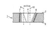
도 1은 두 개의 결합된 홀을 포함하는 본 발명의 뼈플레이트의 평면도이다.1 is a plan view of a bone plate of the present invention comprising two coupled holes.
도 2는 결합된 홀의 하나의 부분에서 도 1의 뼈플레이트의 종단면도이다.FIG. 2 is a longitudinal sectional view of the bone plate of FIG. 1 in one portion of the joined hole. FIG.
도 1과 도 2에 도시된 뼈플레이트(1)는 상면(2), 뼈와 맞닿는 저면(3), 제 1단부(11), 제 2단부(12)와 뼈스크류를 수용하고 상기 두 단부(11,12) 사이에 형성되며 상기 상면(2)과 상기 저면(3)을 연결하는 네 개의 플레이트 홀을 포함한다.The bone plate 1 shown in FIGS. 1 and 2 accommodates an
상기 제 1단부(11) 가까이에 있는 상기 두 개의 플레이트 홀(4)은 다르고 부분적으로 겹치는 두 개의 보어홀(5,6)에 의해 구성된다. 상기 제 1보어홀(5)은 원형의 실린더형이고, 실린더축(9)과 내측 나사부(7)를 포함한다. 상기 제 2보어홀(6)은 상기 상면(2)으로부터 상기 저면(3)쪽으로 원추대 모양으로 점점 가늘어지고, 그것은 원뿔축(10)과 내측 나사부(8)를 포함한다. 상기 실리더축(9)과 상기 원뿔축(10)은 서로 평행하고, 거리 A = 2㎜ 만큼 떨어져 있다.The two plate holes 4 close to the
상기 겹치는 보어홀(5,6)에 의해 구성되는 두 개의 플레이트 홀(4)의 말단은 상기 뼈플레이트(1)의 점점 가늘어지는 상기 제 1단부(11) 가까이에 형성된다.The ends of the two plate holes 4 constituted by the overlapping bore holes 5, 6 are formed near the tapered
상기 결합된 홀에 인접하는 상기 플레이트 홀(4)은 원뿔이고 각지게 고정되며, 상기 내측 나사부(8)를 포함한다.The plate hole 4 adjacent to the joined hole is conical and angularly fixed and includes the inner threaded
상술한 바와 같이, 본 발명에 의한 뼈플레이트는 종래와 달리 골수내외 모두에 적용할 수 있고, 각진 고정이 가능하며, 크고 작은 교정 모두가 최소로 침습이 가능하다.As described above, the bone plate according to the present invention can be applied to both inside and outside the bone marrow, unlike the prior art, it is possible to fix the angle, both large and small correction can be minimally invasive.
Claims (17)
Translated fromKoreanApplications Claiming Priority (1)
| Application Number | Priority Date | Filing Date | Title |
|---|---|---|---|
| PCT/CH2003/000712WO2005041796A1 (en) | 2003-10-30 | 2003-10-30 | Bone plate |
Publications (2)
| Publication Number | Publication Date |
|---|---|
| KR20060089743A KR20060089743A (en) | 2006-08-09 |
| KR101136203B1true KR101136203B1 (en) | 2012-04-17 |
Family
ID=34529352
Family Applications (1)
| Application Number | Title | Priority Date | Filing Date |
|---|---|---|---|
| KR1020067007559AExpired - Fee RelatedKR101136203B1 (en) | 2003-10-30 | 2003-10-30 | Bone plate |
Country Status (15)
| Country | Link |
|---|---|
| US (1) | US8246661B2 (en) |
| EP (1) | EP1677693B1 (en) |
| JP (1) | JP4398429B2 (en) |
| KR (1) | KR101136203B1 (en) |
| CN (1) | CN100400008C (en) |
| AR (1) | AR047228A1 (en) |
| AT (1) | ATE428362T1 (en) |
| AU (1) | AU2003271507B2 (en) |
| BR (1) | BR0318585B1 (en) |
| CA (1) | CA2545019C (en) |
| DE (1) | DE50311436D1 (en) |
| ES (1) | ES2322575T3 (en) |
| NZ (1) | NZ546739A (en) |
| TW (1) | TWI337072B (en) |
| WO (1) | WO2005041796A1 (en) |
Families Citing this family (118)
| Publication number | Priority date | Publication date | Assignee | Title |
|---|---|---|---|---|
| DK1158915T3 (en)* | 1999-03-09 | 2004-11-08 | Synthes Ag | bone plate |
| US20060129151A1 (en)* | 2002-08-28 | 2006-06-15 | Allen C W | Systems and methods for securing fractures using plates and cable clamps |
| US7722653B2 (en)* | 2003-03-26 | 2010-05-25 | Greatbatch Medical S.A. | Locking bone plate |
| US7951176B2 (en) | 2003-05-30 | 2011-05-31 | Synthes Usa, Llc | Bone plate |
| DE20321551U1 (en) | 2003-08-26 | 2007-12-27 | Synthes Gmbh | bone plate |
| US11259851B2 (en) | 2003-08-26 | 2022-03-01 | DePuy Synthes Products, Inc. | Bone plate |
| ES2295708T3 (en)* | 2003-09-08 | 2008-04-16 | Synthes Gmbh | DEVICE FOR OSEA FIXATION. |
| US7637928B2 (en)* | 2004-01-26 | 2009-12-29 | Synthes Usa, Llc | Variable angle locked bone fixation system |
| US8574268B2 (en)* | 2004-01-26 | 2013-11-05 | DePuy Synthes Product, LLC | Highly-versatile variable-angle bone plate system |
| US11291484B2 (en) | 2004-01-26 | 2022-04-05 | DePuy Synthes Products, Inc. | Highly-versatile variable-angle bone plate system |
| WO2006091827A2 (en) | 2005-02-25 | 2006-08-31 | Regents Of The University Of California | Device and template for canine humeral slide osteotomy |
| US20070093822A1 (en)* | 2005-09-28 | 2007-04-26 | Christof Dutoit | Apparatus and methods for vertebral augmentation using linked expandable bodies |
| US20070162132A1 (en) | 2005-12-23 | 2007-07-12 | Dominique Messerli | Flexible elongated chain implant and method of supporting body tissue with same |
| AR061999A1 (en)* | 2007-07-18 | 2008-08-10 | Pizzicara Mario Angel | BLOCKED PLATE OF COMBINED HOLES, STABILITY CONTROL AND DOUBLE ANGULATION, FOR UNION OF FRACTURED BONES |
| DE102007036943B4 (en)* | 2007-08-04 | 2014-12-31 | Zimmer Gmbh | Foot surgery bone plate |
| US8167918B2 (en)* | 2008-02-19 | 2012-05-01 | Orthohelix Surgical Designs, Inc. | Orthopedic plate for use in the MTP joint |
| AU2009215830B2 (en)* | 2008-02-19 | 2012-07-12 | Stryker Corporation | Orthopedic plates for use in the midfoot |
| US8257403B2 (en)* | 2008-02-19 | 2012-09-04 | Orthohelix Surgical Designs, Inc. | Orthopedic plate for use in the midfoot |
| US8257406B2 (en)* | 2008-02-19 | 2012-09-04 | Orthohelix Surgical Designs, Inc. | Orthopedic plate for use on a single ray in the midfoot |
| US20090228010A1 (en) | 2008-03-10 | 2009-09-10 | Eduardo Gonzalez-Hernandez | Bone fixation system |
| AU2008354730A1 (en) | 2008-04-17 | 2009-10-22 | Toby Orthopaedics, Inc. | Soft tissue attachment system and clip |
| US8551144B2 (en)* | 2008-04-22 | 2013-10-08 | Collab Comlo, LLC | Bone plate system configurable as static or dynamic implant |
| US8784458B1 (en) | 2008-10-10 | 2014-07-22 | Greatbatch Medical S.A. | Polyaxial insert for surgical screws |
| US8870876B2 (en)* | 2009-02-13 | 2014-10-28 | Tarsus Medical Inc. | Methods and devices for treating hallux valgus |
| USD623744S1 (en) | 2009-02-17 | 2010-09-14 | Orthohelix Surgical Designs, Inc. | Orthopedic plate |
| USD623743S1 (en) | 2009-02-17 | 2010-09-14 | Orthohelix Surgical Designs, Inc. | Orthopedic plate |
| USD623745S1 (en) | 2009-02-17 | 2010-09-14 | Orthohelix Surgical Designs, Inc. | Orthopedic plate |
| US20100256687A1 (en)* | 2009-04-01 | 2010-10-07 | Merete Medical Gmbh | Fixation Device and Method of Use for a Ludloff Osteotomy Procedure |
| DE102009016394B4 (en)* | 2009-04-07 | 2016-02-11 | Merete Medical Gmbh | Device for stable-angle fixation and compression of a fracture site or osteotomy on a bone |
| US8986353B2 (en) | 2009-07-09 | 2015-03-24 | Orthohelix Surgical Designs, Inc. | Osteotomy plate, plate driver and method for their use |
| US8758346B2 (en)* | 2009-09-14 | 2014-06-24 | DePuy Synthes Products, LLC | Variable angle compression plate |
| US10390867B2 (en) | 2009-09-18 | 2019-08-27 | Biomet C.V. | Bone plate system and method |
| WO2011035103A2 (en)* | 2009-09-18 | 2011-03-24 | Depuy Products, Inc. | Disposable orthopaedic surgery kit and components |
| US8277459B2 (en)* | 2009-09-25 | 2012-10-02 | Tarsus Medical Inc. | Methods and devices for treating a structural bone and joint deformity |
| EP2515779B1 (en) | 2009-12-22 | 2016-03-02 | Merete Medical GmbH | Bone plate system for osteosynthesis |
| DE102009060396B4 (en)* | 2009-12-22 | 2017-04-13 | Bernhard Clasbrummel | Bone plate with device for angular stable screw fixation and screws therefor |
| CN102740786A (en)* | 2009-12-22 | 2012-10-17 | 托比骨科有限公司 | Bone plate and tool assembly and method for use thereof |
| US8652141B2 (en) | 2010-01-21 | 2014-02-18 | Tarsus Medical Inc. | Methods and devices for treating hallux valgus |
| US8696719B2 (en) | 2010-06-03 | 2014-04-15 | Tarsus Medical Inc. | Methods and devices for treating hallux valgus |
| DE102010025001B4 (en) | 2010-06-24 | 2016-08-04 | Aap Implantate Ag | Fixation system with bone plate and bone screw |
| US8961573B2 (en) | 2010-10-05 | 2015-02-24 | Toby Orthopaedics, Inc. | System and method for facilitating repair and reattachment of comminuted bone portions |
| WO2012058448A2 (en) | 2010-10-27 | 2012-05-03 | Toby Orthopaedics, Llc | System and method for fracture replacement of comminuted bone fractures or portions thereof adjacent bone joints |
| US9138219B2 (en) | 2010-12-29 | 2015-09-22 | Tarsus Medical Inc. | Methods and devices for treating a syndesmosis injury |
| ES2599850T3 (en) | 2011-02-01 | 2017-02-03 | Nextremity Solutions, Inc. | Bone defect repair device |
| WO2012119146A2 (en) | 2011-03-03 | 2012-09-07 | Toby Orthopaedics, Llc | Anterior lesser tuberosity fixed angle fixation device and method of use associated therewith |
| TWI496557B (en)* | 2011-03-03 | 2015-08-21 | Univ Ishou | Bone plate manufacturing method |
| US9480510B2 (en) | 2011-03-23 | 2016-11-01 | Spinecraft, LLC | Devices, systems and methods of attaching same to the spine |
| US9005292B2 (en)* | 2011-05-10 | 2015-04-14 | Hooman M. MELAMED | Vertebral spacer |
| US9907558B2 (en) | 2011-07-08 | 2018-03-06 | Smith & Nephew, Inc. | Osteotomy guide and method |
| DE202011051165U1 (en) | 2011-08-31 | 2011-11-14 | Merete Medical Gmbh | Anatomically adapted, plantar bone plate and bone plate system |
| US9271772B2 (en) | 2011-10-27 | 2016-03-01 | Toby Orthopaedics, Inc. | System and method for fracture replacement of comminuted bone fractures or portions thereof adjacent bone joints |
| US9730797B2 (en) | 2011-10-27 | 2017-08-15 | Toby Orthopaedics, Inc. | Bone joint replacement and repair assembly and method of repairing and replacing a bone joint |
| US9402667B2 (en) | 2011-11-09 | 2016-08-02 | Eduardo Gonzalez-Hernandez | Apparatus and method for use of the apparatus for fracture fixation of the distal humerus |
| DE102012103894B4 (en) | 2012-05-03 | 2016-10-27 | Merete Medical Gmbh | Bone plate system for osteosynthesis |
| US9283008B2 (en) | 2012-12-17 | 2016-03-15 | Toby Orthopaedics, Inc. | Bone plate for plate osteosynthesis and method for use thereof |
| US9103367B2 (en) | 2013-03-14 | 2015-08-11 | Imds Llc | Polyaxial locking interface |
| US9433454B2 (en) | 2013-03-14 | 2016-09-06 | Amei Technologies, Inc. | Variable angle screws, plates and systems |
| US9404525B2 (en) | 2013-03-14 | 2016-08-02 | Imds Llc | Polyaxial locking interface |
| US9545276B2 (en) | 2013-03-15 | 2017-01-17 | Aristotech Industries Gmbh | Fixation device and method of use for a lapidus-type plantar hallux valgus procedure |
| US9333014B2 (en) | 2013-03-15 | 2016-05-10 | Eduardo Gonzalez-Hernandez | Bone fixation and reduction apparatus and method for fixation and reduction of a distal bone fracture and malunion |
| US9510880B2 (en) | 2013-08-13 | 2016-12-06 | Zimmer, Inc. | Polyaxial locking mechanism |
| US9468479B2 (en) | 2013-09-06 | 2016-10-18 | Cardinal Health 247, Inc. | Bone plate |
| USD745162S1 (en) | 2014-01-27 | 2015-12-08 | Merete Medical Gmbh | Bone plate |
| KR101601730B1 (en)* | 2014-02-03 | 2016-03-09 | 고려대학교 산학협력단 | Osteosynthesis plate and osteosynthesis device including the same |
| US10226287B2 (en) | 2014-03-31 | 2019-03-12 | Association For The Advancement Of Musculoskeletal | Bone plate with versatile screw holes |
| US10245088B2 (en) | 2015-01-07 | 2019-04-02 | Treace Medical Concepts, Inc. | Bone plating system and method |
| US10314626B2 (en)* | 2015-01-16 | 2019-06-11 | DePuy Synthes Procucts, Inc. | Washer plate |
| WO2016134160A1 (en) | 2015-02-18 | 2016-08-25 | Treace Medical Concepts, Inc. | Bone plating kit for foot and ankle applications |
| CN104739496A (en)* | 2015-03-12 | 2015-07-01 | 创辉医疗器械江苏有限公司 | Fine-thread universal bone fracture plate |
| US11076898B2 (en) | 2015-08-27 | 2021-08-03 | Globus Medical, Inc. | Proximal humeral stabilization system |
| US10687874B2 (en) | 2015-08-27 | 2020-06-23 | Globus Medical, Inc | Proximal humeral stabilization system |
| US11197682B2 (en) | 2015-08-27 | 2021-12-14 | Globus Medical, Inc. | Proximal humeral stabilization system |
| US10130402B2 (en) | 2015-09-25 | 2018-11-20 | Globus Medical, Inc. | Bone fixation devices having a locking feature |
| US9974581B2 (en) | 2015-11-20 | 2018-05-22 | Globus Medical, Inc. | Expandable intramedullary systems and methods of using the same |
| US9795411B2 (en) | 2016-03-02 | 2017-10-24 | Globus Medical, Inc. | Fixators for bone stabilization and associated systems and methods |
| KR101722252B1 (en)* | 2016-03-18 | 2017-04-03 | 이동훈 | Intramedullary nail having an anti-tilting fuction |
| US10531905B2 (en) | 2016-04-19 | 2020-01-14 | Globus Medical, Inc. | Implantable compression screws |
| AU2017274445B2 (en)* | 2016-06-02 | 2022-06-16 | In2Bones Usa, Llc | Plantar bone fusion plate |
| CN109922741B (en)* | 2016-06-02 | 2022-11-08 | 联骨美国有限责任公司 | Foot sole bone fusion plate |
| US10687873B2 (en) | 2016-08-17 | 2020-06-23 | Globus Medical Inc. | Stabilization systems |
| US11141204B2 (en) | 2016-08-17 | 2021-10-12 | Globus Medical Inc. | Wrist stabilization systems |
| US11331128B2 (en) | 2016-08-17 | 2022-05-17 | Globus Medical Inc. | Distal radius stabilization system |
| US11197701B2 (en) | 2016-08-17 | 2021-12-14 | Globus Medical, Inc. | Stabilization systems |
| US11432857B2 (en) | 2016-08-17 | 2022-09-06 | Globus Medical, Inc. | Stabilization systems |
| US10751098B2 (en) | 2016-08-17 | 2020-08-25 | Globus Medical Inc. | Stabilization systems |
| US10420596B2 (en) | 2016-08-17 | 2019-09-24 | Globus Medical, Inc. | Volar distal radius stabilization system |
| US10575884B2 (en) | 2016-08-17 | 2020-03-03 | Globus Medical, Inc. | Fracture plates, systems, and methods |
| US10383668B2 (en) | 2016-08-17 | 2019-08-20 | Globus Medical, Inc. | Volar distal radius stabilization system |
| US11213327B2 (en) | 2016-08-17 | 2022-01-04 | Globus Medical, Inc. | Fracture plates, systems, and methods |
| US10820930B2 (en) | 2016-09-08 | 2020-11-03 | DePuy Synthes Products, Inc. | Variable angle bone plate |
| US10905476B2 (en) | 2016-09-08 | 2021-02-02 | DePuy Synthes Products, Inc. | Variable angle bone plate |
| US10624686B2 (en) | 2016-09-08 | 2020-04-21 | DePuy Synthes Products, Inc. | Variable angel bone plate |
| US10492803B2 (en)* | 2016-09-22 | 2019-12-03 | Globus Medical, Inc. | Systems and methods for intramedullary nail implantation |
| US10299847B2 (en) | 2016-09-22 | 2019-05-28 | Globus Medical, Inc. | Systems and methods for intramedullary nail implantation |
| US10881438B2 (en) | 2017-03-10 | 2021-01-05 | Globus Medical, Inc. | Clavicle fixation system |
| US10905477B2 (en) | 2017-03-13 | 2021-02-02 | Globus Medical, Inc. | Bone stabilization systems |
| US10368928B2 (en) | 2017-03-13 | 2019-08-06 | Globus Medical, Inc. | Bone stabilization systems |
| US10456174B2 (en)* | 2017-07-31 | 2019-10-29 | Medos International Sarl | Connectors for use in systems and methods for reducing the risk of proximal junctional kyphosis |
| US10463403B2 (en) | 2017-07-31 | 2019-11-05 | Medos International Sarl | Systems and methods for reducing the risk of proximal junctional kyphosis using a bone anchor or other attachment point |
| US10856920B2 (en) | 2017-09-13 | 2020-12-08 | Globus Medical Inc. | Bone stabilization systems |
| US12318122B2 (en) | 2017-09-13 | 2025-06-03 | Globus Medical, Inc. | Bone stabilization systems |
| US11096730B2 (en) | 2017-09-13 | 2021-08-24 | Globus Medical Inc. | Bone stabilization systems |
| US11071570B2 (en) | 2018-03-02 | 2021-07-27 | Globus Medical, Inc. | Distal tibial plating system |
| US11224468B2 (en) | 2018-03-02 | 2022-01-18 | Globus Medical, Inc. | Distal tibial plating system |
| US11026727B2 (en) | 2018-03-20 | 2021-06-08 | DePuy Synthes Products, Inc. | Bone plate with form-fitting variable-angle locking hole |
| US10772665B2 (en) | 2018-03-29 | 2020-09-15 | DePuy Synthes Products, Inc. | Locking structures for affixing bone anchors to a bone plate, and related systems and methods |
| US11141172B2 (en) | 2018-04-11 | 2021-10-12 | Globus Medical, Inc. | Method and apparatus for locking a drill guide in a polyaxial hole |
| US11013541B2 (en) | 2018-04-30 | 2021-05-25 | DePuy Synthes Products, Inc. | Threaded locking structures for affixing bone anchors to a bone plate, and related systems and methods |
| US11583323B2 (en) | 2018-07-12 | 2023-02-21 | Treace Medical Concepts, Inc. | Multi-diameter bone pin for installing and aligning bone fixation plate while minimizing bone damage |
| US10925651B2 (en) | 2018-12-21 | 2021-02-23 | DePuy Synthes Products, Inc. | Implant having locking holes with collection cavity for shavings |
| US11202663B2 (en) | 2019-02-13 | 2021-12-21 | Globus Medical, Inc. | Proximal humeral stabilization systems and methods thereof |
| US11890039B1 (en) | 2019-09-13 | 2024-02-06 | Treace Medical Concepts, Inc. | Multi-diameter K-wire for orthopedic applications |
| US12185995B2 (en) | 2019-10-09 | 2025-01-07 | Globus Medical, Inc. | Bone stabilization systems |
| US11129627B2 (en) | 2019-10-30 | 2021-09-28 | Globus Medical, Inc. | Method and apparatus for inserting a bone plate |
| US11723647B2 (en) | 2019-12-17 | 2023-08-15 | Globus Medical, Inc. | Syndesmosis fixation assembly |
| US11395686B2 (en) | 2020-04-20 | 2022-07-26 | Khay-Yong Saw | Bone fixation plate and method of using thereof |
| WO2022031881A1 (en)* | 2020-08-05 | 2022-02-10 | Children's Hospital Los Angeles | Pediatric long bone fixation device |
| US12064150B2 (en) | 2022-01-19 | 2024-08-20 | Globus Medical Inc. | System and method for treating bone fractures |
Citations (3)
| Publication number | Priority date | Publication date | Assignee | Title |
|---|---|---|---|---|
| US6348052B1 (en)* | 1996-07-16 | 2002-02-19 | Giacomo J. Sammarco | Internal fixation plate |
| US20020183752A1 (en)* | 2000-01-27 | 2002-12-05 | Beatrice Steiner | Bone plate |
| US6719759B2 (en)* | 1999-03-09 | 2004-04-13 | Synthes Ag Chur | Bone plate |
Family Cites Families (118)
| Publication number | Priority date | Publication date | Assignee | Title |
|---|---|---|---|---|
| US3630A (en)* | 1844-06-13 | Tiwtte | ||
| FR742618A (en) | 1933-03-10 | |||
| US3463148A (en)* | 1966-01-20 | 1969-08-26 | Richards Mfg Co | Bone plate |
| CH462375A (en)* | 1966-06-22 | 1968-09-15 | Synthes Ag | Osteosynthetic pressure plate |
| USRE28841E (en)* | 1966-06-22 | 1976-06-08 | Synthes A.G. | Osteosynthetic pressure plate construction |
| USRE31628E (en)* | 1966-06-22 | 1984-07-10 | Synthes Ag | Osteosynthetic pressure plate construction |
| US3630261A (en) | 1968-02-27 | 1971-12-28 | Rex Chainbelt Inc | Frictional antirotation device |
| US3716050A (en)* | 1971-02-11 | 1973-02-13 | F Johnston | Olecranon plate |
| US3741205A (en)* | 1971-06-14 | 1973-06-26 | K Markolf | Bone fixation plate |
| US3779240A (en)* | 1972-03-31 | 1973-12-18 | S Kondo | Compression plate for osteosynthesis |
| FR2233973A1 (en) | 1973-06-25 | 1975-01-17 | Chatin Robert | Osteosynthesis plate for femoral fracture surgery - has anchoring holes in ablong flat portion and widened blade |
| DE2438669C3 (en)* | 1974-08-12 | 1978-10-05 | Bezold Geb. Graefin Von Sponeck, Margarete Von, 8035 Gauting | Osteosynthesis plate |
| CH611147A5 (en) | 1977-01-07 | 1979-05-31 | Mueller Kurt | Osteosynthesis compression plate |
| GB1565178A (en)* | 1977-02-24 | 1980-04-16 | Interfix Ltd | Bone screw |
| CH613858A5 (en)* | 1977-04-22 | 1979-10-31 | Straumann Inst Ag | |
| FR2405062A1 (en) | 1977-10-10 | 1979-05-04 | Dayan Robert | Surgical repair plate for lower fractures of femur - has concave cross section and enlarged end with staggered countersunk screw holes |
| FR2405706A1 (en) | 1977-10-14 | 1979-05-11 | Dayan Robert | Surgical repair plate for humerus lower end fracture - has end with unequal curved branches and countersunk holes for fixing screws |
| FR2405705A1 (en) | 1977-10-14 | 1979-05-11 | Dayan Robert | Surgical repair plate for tibia upper end fracture - has elongated length with enlarged head and countersunk for fixing screws |
| FR2416683A1 (en)* | 1978-02-10 | 1979-09-07 | Judet Robert | IMPROVEMENTS TO OSTEO-SYNTHESIS DEVICES |
| CA1112803A (en) | 1978-08-17 | 1981-11-24 | George W. Bagby | Internal fracture plate assembly with releasing feature |
| CH645013A5 (en)* | 1980-04-14 | 1984-09-14 | Wenk Wilh Ag | Osteosynthetic COMPRESSION PLATE. |
| CH648197A5 (en)* | 1980-05-28 | 1985-03-15 | Synthes Ag | IMPLANT AND SCREW FASTENING ON ITS BONE. |
| IT1132843B (en)* | 1980-09-15 | 1986-07-09 | Cise Spa | PLATE FOR JOINTS OF SEPARATE BONE PORTIONS FROM FRACTURE |
| CH651192A5 (en) | 1980-11-20 | 1985-09-13 | Synthes Ag | OSTEOSYNTHETIC DEVICE AND CORRESPONDING DRILL GAUGE. |
| US4338926A (en)* | 1980-11-21 | 1982-07-13 | Howmedica, Inc. | Bone fracture prosthesis with controlled stiffness |
| DE8034274U1 (en) | 1980-12-23 | 1981-05-27 | Schwan-Stabilo Schwanhäußer GmbH & Co, 8500 Nürnberg | COSMETIC PEN |
| CH650915A5 (en)* | 1981-03-16 | 1985-08-30 | Synthes Ag | DEVICE FOR STABILIZING THE AREA OF A BONE BREAK OR OSTEOTOMY. |
| AT378324B (en)* | 1982-09-13 | 1985-07-25 | Streli Elke | TINNED PLATE FOR FIXING THE BONES IN THE BODIES IN BONE BREAKS |
| US4612923A (en)* | 1983-12-01 | 1986-09-23 | Ethicon, Inc. | Glass-filled, absorbable surgical devices |
| GB2158716B (en)* | 1984-05-18 | 1987-09-30 | Technomed Gmk | Bone joining plate |
| DE8431616U1 (en)* | 1984-10-27 | 1984-12-20 | Howmedica International, Inc. Zweigniederlassung Kiel, 2314 Schönkirchen | Plate for osteosynthesis |
| DE3442004C1 (en) | 1984-11-16 | 1986-04-24 | Otte, Heinz, Dr.med., 8712 Volkach | Bone fixation apparatus for the treatment of fractures |
| US4683878A (en)* | 1985-04-29 | 1987-08-04 | Kirschner Medical Corporation | Osteosynthetic fixation plate |
| SU1279626A1 (en) | 1985-06-06 | 1986-12-30 | Центральный научно-исследовательский институт травматологии и ортопедии им.Н.Н.Приорова | Compression device for osteosynthesis |
| DE8519854U1 (en) | 1985-07-05 | 1986-04-30 | Mecron Medizinische Produkte Gmbh, 1000 Berlin | Self-tightening straight bone plate |
| US5013315A (en) | 1985-07-12 | 1991-05-07 | Minnesota Mining And Manufacturing Company | Semiabsorbable bone plate spacer |
| CH668174A5 (en)* | 1985-08-30 | 1988-12-15 | Synthes Ag | OSTEOSYNTHETIC PRINT PLATE. |
| US4776329A (en)* | 1985-09-20 | 1988-10-11 | Richards Medical Company | Resorbable compressing screw and method |
| PL147580B1 (en)* | 1986-04-14 | 1989-06-30 | Plate for uniting epiphysis and diaphysis of broken bone | |
| US4776330A (en)* | 1986-06-23 | 1988-10-11 | Pfizer Hospital Products Group, Inc. | Modular femoral fixation system |
| US5190544A (en)* | 1986-06-23 | 1993-03-02 | Pfizer Hospital Products Group, Inc. | Modular femoral fixation system |
| US4781183A (en)* | 1986-08-27 | 1988-11-01 | American Cyanamid Company | Surgical prosthesis |
| WO1988003781A1 (en) | 1986-11-25 | 1988-06-02 | Synthes Ag | Osteosynthetic device |
| US5151103A (en)* | 1987-11-03 | 1992-09-29 | Synthes (U.S.A.) | Point contact bone compression plate |
| MX170527B (en)* | 1987-11-03 | 1993-08-30 | Synthes Ag | IMPLEMENTATION FOR OSTEOSYNTHESIS |
| CH673762A5 (en)* | 1987-12-02 | 1990-04-12 | Synthes Ag | |
| US4858601A (en)* | 1988-05-27 | 1989-08-22 | Glisson Richard R | Adjustable compression bone screw |
| DE8808123U1 (en)* | 1988-06-24 | 1988-09-22 | Herzberg, Wolfgang, Dr. med., 2000 Wedel | Tab screw for osteosynthesis of pertrochanteric fractures |
| US4927421A (en)* | 1989-05-15 | 1990-05-22 | Marlowe Goble E | Process of endosteal fixation of a ligament |
| DE3923995A1 (en) | 1989-07-20 | 1991-01-31 | Lutz Biedermann | BONE STABILIZING ELEMENT |
| US5006120A (en)* | 1989-10-10 | 1991-04-09 | Carter Peter R | Distal radial fracture set and method for repairing distal radial fractures |
| US5085660A (en)* | 1990-11-19 | 1992-02-04 | Lin Kwan C | Innovative locking plate system |
| US5514138A (en)* | 1991-02-08 | 1996-05-07 | Pfizer Inc. | Connector having a stop member |
| FR2674118B1 (en) | 1991-03-19 | 1998-02-20 | Benoit Girard Cie Sa | SPINAL OSTEOSYNTHESIS DEVICE. |
| CH686222A5 (en) | 1991-05-30 | 1996-02-15 | Synthes Ag | The trochanter stabilization. |
| US5129901A (en)* | 1991-06-10 | 1992-07-14 | Decoste Vern X | Cannulated orthopedic screw |
| US5275601A (en)* | 1991-09-03 | 1994-01-04 | Synthes (U.S.A) | Self-locking resorbable screws and plates for internal fixation of bone fractures and tendon-to-bone attachment |
| US5360448A (en)* | 1991-10-07 | 1994-11-01 | Thramann Jeffrey J | Porous-coated bone screw for securing prosthesis |
| CH686339A5 (en)* | 1991-12-10 | 1996-03-15 | Synthes Ag | Nut for the plate fixation. |
| US5304180A (en)* | 1992-01-17 | 1994-04-19 | Slocum D Barclay | Tibial osteotomy fixation plate |
| US5197966A (en)* | 1992-05-22 | 1993-03-30 | Sommerkamp T Greg | Radiodorsal buttress blade plate implant for repairing distal radius fractures |
| US5324290A (en)* | 1992-09-24 | 1994-06-28 | Danek Medical, Inc. | Anterior thoracolumbar plate |
| US5336224A (en)* | 1992-11-30 | 1994-08-09 | Ace Medical Company | Bone fixation plate |
| CA2132832C (en)* | 1993-01-25 | 2001-08-14 | Synthes Ag | Lock washer for bone plate osteosynthesis |
| US5364399A (en)* | 1993-02-05 | 1994-11-15 | Danek Medical, Inc. | Anterior cervical plating system |
| IL105183A (en)* | 1993-03-28 | 1996-07-23 | Yehiel Gotfried | Surgical device for connection of fractured bones |
| FR2711505B1 (en)* | 1993-10-25 | 1995-12-29 | Tornier Sa | Device for synthesizing fractures of the upper end of the femur. |
| DE9321544U1 (en) | 1993-12-09 | 1999-09-23 | Königsee Implantate und Instrumente zur Ostheosynthese GmbH, 07426 Königsee | Osteosynthetic plate |
| DE4341980B4 (en) | 1993-12-09 | 2005-02-17 | Königsee Implantate und Instrumente zur Ostheosynthese GmbH | Osteosynthetic bone plate |
| DE4343117C2 (en) | 1993-12-17 | 1999-11-04 | Dietmar Wolter | Bone fixation system |
| US5674222A (en)* | 1994-06-01 | 1997-10-07 | Synthes (U.S.A.) | Forked plate |
| DE4438264C2 (en) | 1994-09-08 | 1996-11-28 | Schaefer Micomed Gmbh | Osteosynthesis device |
| US5810823A (en)* | 1994-09-12 | 1998-09-22 | Synthes (U.S.A.) | Osteosynthetic bone plate and lock washer |
| US5601553A (en)* | 1994-10-03 | 1997-02-11 | Synthes (U.S.A.) | Locking plate and bone screw |
| US5976141A (en)* | 1995-02-23 | 1999-11-02 | Synthes (U.S.A.) | Threaded insert for bone plate screw hole |
| CA2189744C (en)* | 1995-03-27 | 2003-09-16 | Gilbert Talos | Bone plate |
| US5520690A (en)* | 1995-04-13 | 1996-05-28 | Errico; Joseph P. | Anterior spinal polyaxial locking screw plate assembly |
| US5607428A (en)* | 1995-05-01 | 1997-03-04 | Lin; Kwan C. | Orthopedic fixation device having a double-threaded screw |
| DE59509247D1 (en)* | 1995-09-06 | 2001-06-13 | Synthes Ag | BONE PLATE |
| US5749872A (en)* | 1995-09-08 | 1998-05-12 | Ace Medical Company | Keyed/keyless barrel for bone plates |
| AT937U3 (en) | 1996-03-26 | 1996-12-27 | Stoffella Rudolf Dr | IMPLANT FOR FIXING AN OSTEOTOMY |
| US5868749A (en)* | 1996-04-05 | 1999-02-09 | Reed; Thomas M. | Fixation devices |
| US5702399A (en)* | 1996-05-16 | 1997-12-30 | Pioneer Laboratories, Inc. | Surgical cable screw connector |
| WO1997047251A1 (en)* | 1996-06-14 | 1997-12-18 | Depuy Ace Medical Company | Upper extremity bone plate |
| ES2297092T3 (en)* | 1997-02-11 | 2008-05-01 | Warsaw Orthopedic, Inc. | PREVIOUS CERVICAL PLATE OF UNIQUE BLOCK. |
| US5810821A (en)* | 1997-03-28 | 1998-09-22 | Biomet Inc. | Bone fixation screw system |
| FR2766353B1 (en)* | 1997-07-28 | 1999-11-26 | Dimso Sa | IMPLANT, ESPECIALLY ANTERIOR CERVICAL PLATE |
| US5954722A (en)* | 1997-07-29 | 1999-09-21 | Depuy Acromed, Inc. | Polyaxial locking plate |
| US6454769B2 (en)* | 1997-08-04 | 2002-09-24 | Spinal Concepts, Inc. | System and method for stabilizing the human spine with a bone plate |
| US6030389A (en)* | 1997-08-04 | 2000-02-29 | Spinal Concepts, Inc. | System and method for stabilizing the human spine with a bone plate |
| ES2196356T3 (en)* | 1997-09-04 | 2003-12-16 | Synthes Ag | SYNTHRICAL PLATE FOR OSTEOSINTESIS. |
| US5938664A (en)* | 1998-03-31 | 1999-08-17 | Zimmer, Inc. | Orthopaedic bone plate |
| CA2330705A1 (en)* | 1998-04-29 | 1999-11-04 | Dimso (Distribution Medicale Du Sud-Ouest) | Backbone osteosynthesis system for anterior fixing |
| US6228085B1 (en)* | 1998-07-14 | 2001-05-08 | Theken Surgical Llc | Bone fixation system |
| DE19832513A1 (en) | 1998-07-20 | 2000-02-17 | Impag Gmbh Medizintechnik | Fastening arrangement |
| AT406011B (en) | 1998-07-30 | 2000-01-25 | Stoffella Rudolf Dr | Implant for fixing two bone fragments to each other |
| US6183475B1 (en)* | 1998-12-18 | 2001-02-06 | Sulzer Orthopedics Inc. | Distal femoral osteotomy system and method |
| DE19858889B4 (en)* | 1998-12-19 | 2008-08-07 | Wolter, Dietmar, Prof. Dr.Med. | Fixation system for bones |
| US6129730A (en)* | 1999-02-10 | 2000-10-10 | Depuy Acromed, Inc. | Bi-fed offset pitch bone screw |
| CN1149057C (en)* | 1999-03-09 | 2004-05-12 | 库尔斯恩蒂斯股份公司 | Bone plate with conical screw threads |
| AU3954200A (en) | 1999-05-03 | 2000-11-17 | Medartis Ag | Blockable bone plate |
| CN1172634C (en)* | 1999-09-13 | 2004-10-27 | 库尔斯恩蒂斯股份公司 | Bone plating system |
| DE19944120B4 (en)* | 1999-09-15 | 2008-08-28 | Ulrich Gmbh & Co. Kg | Bone screw for variable angle connection with a side member |
| US6358250B1 (en)* | 2000-02-01 | 2002-03-19 | Hand Innovations, Inc. | Volar fixation system |
| US6440135B2 (en)* | 2000-02-01 | 2002-08-27 | Hand Innovations, Inc. | Volar fixation system with articulating stabilization pegs |
| US6235033B1 (en)* | 2000-04-19 | 2001-05-22 | Synthes (Usa) | Bone fixation assembly |
| DK1294298T3 (en)* | 2000-06-26 | 2005-01-17 | Synthes Ag | Bone plate for osteosynthesis |
| DE20122742U1 (en)* | 2001-05-28 | 2007-06-14 | Synthes Ag Chur, Chur | Bone plate for fixing proximal humerus fracture, has screw holes with partial internal threads or partial rotating taper grooves, where pitch of internal threads or taper grooves lies within range of specific millimeter |
| US6955677B2 (en)* | 2002-10-15 | 2005-10-18 | The University Of North Carolina At Chapel Hill | Multi-angular fastening apparatus and method for surgical bone screw/plate systems |
| USD479331S1 (en)* | 2002-11-05 | 2003-09-02 | Zimmer | Orthopedic bone plate |
| US7044953B2 (en)* | 2003-02-27 | 2006-05-16 | Stryker Leibinger Gmbh & Co. Kg | Compression bone screw |
| US7722653B2 (en) | 2003-03-26 | 2010-05-25 | Greatbatch Medical S.A. | Locking bone plate |
| DE20309361U1 (en) | 2003-04-11 | 2003-09-18 | Königsee Implantate und Instrumente zur Ostheosynthese GmbH, 07426 Königsee | Osteosynthesis, especially an angle-stable radius plate, for the surgical treatment of bone fractures |
| DE20309036U1 (en)* | 2003-06-11 | 2003-09-11 | Hein, Kristin-Eliane, 83052 Bruckmühl | Support belt-cushion for baby born by caesarean section and resting on the abdomen of a nursing mother |
| DE20321551U1 (en)* | 2003-08-26 | 2007-12-27 | Synthes Gmbh | bone plate |
| ES2295708T3 (en)* | 2003-09-08 | 2008-04-16 | Synthes Gmbh | DEVICE FOR OSEA FIXATION. |
| US7637928B2 (en)* | 2004-01-26 | 2009-12-29 | Synthes Usa, Llc | Variable angle locked bone fixation system |
| US7229445B2 (en)* | 2004-06-21 | 2007-06-12 | Synthes (Usa) | Bone plate with bladed portion |
- 2003
- 2003-10-30DEDE50311436Tpatent/DE50311436D1/ennot_activeExpired - Lifetime
- 2003-10-30ATAT03753216Tpatent/ATE428362T1/enactive
- 2003-10-30JPJP2005510082Apatent/JP4398429B2/ennot_activeExpired - Fee Related
- 2003-10-30EPEP03753216Apatent/EP1677693B1/ennot_activeExpired - Lifetime
- 2003-10-30KRKR1020067007559Apatent/KR101136203B1/ennot_activeExpired - Fee Related
- 2003-10-30BRBRPI0318585-0Apatent/BR0318585B1/ennot_activeIP Right Cessation
- 2003-10-30CNCNB2003801105655Apatent/CN100400008C/ennot_activeExpired - Fee Related
- 2003-10-30NZNZ546739Apatent/NZ546739A/enunknown
- 2003-10-30ESES03753216Tpatent/ES2322575T3/ennot_activeExpired - Lifetime
- 2003-10-30WOPCT/CH2003/000712patent/WO2005041796A1/enactiveApplication Filing
- 2003-10-30AUAU2003271507Apatent/AU2003271507B2/ennot_activeCeased
- 2003-10-30CACA2545019Apatent/CA2545019C/ennot_activeExpired - Fee Related
- 2004
- 2004-10-22TWTW093132078Apatent/TWI337072B/ennot_activeIP Right Cessation
- 2004-10-26ARARP040103888Apatent/AR047228A1/enunknown
- 2006
- 2006-05-01USUS11/416,489patent/US8246661B2/enactiveActive
Patent Citations (3)
| Publication number | Priority date | Publication date | Assignee | Title |
|---|---|---|---|---|
| US6348052B1 (en)* | 1996-07-16 | 2002-02-19 | Giacomo J. Sammarco | Internal fixation plate |
| US6719759B2 (en)* | 1999-03-09 | 2004-04-13 | Synthes Ag Chur | Bone plate |
| US20020183752A1 (en)* | 2000-01-27 | 2002-12-05 | Beatrice Steiner | Bone plate |
Also Published As
| Publication number | Publication date |
|---|---|
| WO2005041796A1 (en) | 2005-05-12 |
| AU2003271507B2 (en) | 2009-04-09 |
| CA2545019C (en) | 2012-02-28 |
| KR20060089743A (en) | 2006-08-09 |
| US8246661B2 (en) | 2012-08-21 |
| EP1677693A1 (en) | 2006-07-12 |
| AU2003271507A1 (en) | 2005-05-19 |
| DE50311436D1 (en) | 2009-05-28 |
| CA2545019A1 (en) | 2005-05-12 |
| ATE428362T1 (en) | 2009-05-15 |
| EP1677693B1 (en) | 2009-04-15 |
| TWI337072B (en) | 2011-02-11 |
| BR0318585B1 (en) | 2012-05-02 |
| NZ546739A (en) | 2009-02-28 |
| JP4398429B2 (en) | 2010-01-13 |
| CN1859880A (en) | 2006-11-08 |
| BR0318585A (en) | 2006-10-10 |
| JP2007509637A (en) | 2007-04-19 |
| ES2322575T3 (en) | 2009-06-23 |
| TW200514548A (en) | 2005-05-01 |
| AR047228A1 (en) | 2006-01-11 |
| CN100400008C (en) | 2008-07-09 |
| US20070016205A1 (en) | 2007-01-18 |
Similar Documents
| Publication | Publication Date | Title |
|---|---|---|
| KR101136203B1 (en) | Bone plate | |
| KR101387162B1 (en) | Nail system and method for an olecaranon osteotomy | |
| US4978349A (en) | Fixation plate | |
| KR100904142B1 (en) | Intramedullary fixation assembly and devices and methods for installing the same | |
| US9492213B2 (en) | Volar fixation system | |
| US6364882B1 (en) | Volar fixation system | |
| JP3545729B2 (en) | Rocking nail | |
| KR101104660B1 (en) | Locking bone plate | |
| JP2004081860A (en) | Humerus pin | |
| RU2396919C2 (en) | Plate for fixation of small fragments in humeral bone | |
| US8419735B2 (en) | Nail locking systems | |
| US7713289B2 (en) | Device for fixing a longitudinal carrier to a bone fixing element | |
| US20210121209A1 (en) | Intramedullary fixation nail and method of use | |
| US11026698B2 (en) | Osteotomy system and method of use | |
| US11109903B2 (en) | Cannulated nail extractor | |
| US20250275776A1 (en) | Drill Guides For Bone Plates | |
| RU50807U1 (en) | CONDUCTOR FOR INTRAMEDULAR FEMAL NAIL |
Legal Events
| Date | Code | Title | Description |
|---|---|---|---|
| PA0105 | International application | St.27 status event code:A-0-1-A10-A15-nap-PA0105 | |
| P11-X000 | Amendment of application requested | St.27 status event code:A-2-2-P10-P11-nap-X000 | |
| P13-X000 | Application amended | St.27 status event code:A-2-2-P10-P13-nap-X000 | |
| PG1501 | Laying open of application | St.27 status event code:A-1-1-Q10-Q12-nap-PG1501 | |
| A201 | Request for examination | ||
| PA0201 | Request for examination | St.27 status event code:A-1-2-D10-D11-exm-PA0201 | |
| E902 | Notification of reason for refusal | ||
| PE0902 | Notice of grounds for rejection | St.27 status event code:A-1-2-D10-D21-exm-PE0902 | |
| P11-X000 | Amendment of application requested | St.27 status event code:A-2-2-P10-P11-nap-X000 | |
| P13-X000 | Application amended | St.27 status event code:A-2-2-P10-P13-nap-X000 | |
| E90F | Notification of reason for final refusal | ||
| PE0902 | Notice of grounds for rejection | St.27 status event code:A-1-2-D10-D21-exm-PE0902 | |
| P11-X000 | Amendment of application requested | St.27 status event code:A-2-2-P10-P11-nap-X000 | |
| P13-X000 | Application amended | St.27 status event code:A-2-2-P10-P13-nap-X000 | |
| E701 | Decision to grant or registration of patent right | ||
| PE0701 | Decision of registration | St.27 status event code:A-1-2-D10-D22-exm-PE0701 | |
| GRNT | Written decision to grant | ||
| PR0701 | Registration of establishment | St.27 status event code:A-2-4-F10-F11-exm-PR0701 | |
| PR1002 | Payment of registration fee | St.27 status event code:A-2-2-U10-U12-oth-PR1002 Fee payment year number:1 | |
| PG1601 | Publication of registration | St.27 status event code:A-4-4-Q10-Q13-nap-PG1601 | |
| PR1001 | Payment of annual fee | St.27 status event code:A-4-4-U10-U11-oth-PR1001 Fee payment year number:4 | |
| LAPS | Lapse due to unpaid annual fee | ||
| PC1903 | Unpaid annual fee | St.27 status event code:A-4-4-U10-U13-oth-PC1903 Not in force date:20160406 Payment event data comment text:Termination Category : DEFAULT_OF_REGISTRATION_FEE | |
| PC1903 | Unpaid annual fee | St.27 status event code:N-4-6-H10-H13-oth-PC1903 Ip right cessation event data comment text:Termination Category : DEFAULT_OF_REGISTRATION_FEE Not in force date:20160406 |