KR101134799B1 - Portable terminal - Google Patents
Portable terminalDownload PDFInfo
- Publication number
- KR101134799B1 KR101134799B1KR1020060054086AKR20060054086AKR101134799B1KR 101134799 B1KR101134799 B1KR 101134799B1KR 1020060054086 AKR1020060054086 AKR 1020060054086AKR 20060054086 AKR20060054086 AKR 20060054086AKR 101134799 B1KR101134799 B1KR 101134799B1
- Authority
- KR
- South Korea
- Prior art keywords
- sound
- receiver
- passage
- portable terminal
- horizontal direction
- Prior art date
- Legal status (The legal status is an assumption and is not a legal conclusion. Google has not performed a legal analysis and makes no representation as to the accuracy of the status listed.)
- Expired - Fee Related
Links
Images


Classifications
- H—ELECTRICITY
- H04—ELECTRIC COMMUNICATION TECHNIQUE
- H04B—TRANSMISSION
- H04B1/00—Details of transmission systems, not covered by a single one of groups H04B3/00 - H04B13/00; Details of transmission systems not characterised by the medium used for transmission
- H04B1/38—Transceivers, i.e. devices in which transmitter and receiver form a structural unit and in which at least one part is used for functions of transmitting and receiving
- H—ELECTRICITY
- H04—ELECTRIC COMMUNICATION TECHNIQUE
- H04M—TELEPHONIC COMMUNICATION
- H04M1/00—Substation equipment, e.g. for use by subscribers
- H04M1/02—Constructional features of telephone sets
- H04M1/0202—Portable telephone sets, e.g. cordless phones, mobile phones or bar type handsets
- H04M1/0206—Portable telephones comprising a plurality of mechanically joined movable body parts, e.g. hinged housings
- H04M1/0208—Portable telephones comprising a plurality of mechanically joined movable body parts, e.g. hinged housings characterized by the relative motions of the body parts
- H04M1/0225—Rotatable telephones, i.e. the body parts pivoting to an open position around an axis perpendicular to the plane they define in closed position
- H04M1/0233—Including a rotatable display body part
- H—ELECTRICITY
- H04—ELECTRIC COMMUNICATION TECHNIQUE
- H04M—TELEPHONIC COMMUNICATION
- H04M1/00—Substation equipment, e.g. for use by subscribers
- H04M1/02—Constructional features of telephone sets
- H04M1/03—Constructional features of telephone transmitters or receivers, e.g. telephone hand-sets
- H—ELECTRICITY
- H04—ELECTRIC COMMUNICATION TECHNIQUE
- H04R—LOUDSPEAKERS, MICROPHONES, GRAMOPHONE PICK-UPS OR LIKE ACOUSTIC ELECTROMECHANICAL TRANSDUCERS; DEAF-AID SETS; PUBLIC ADDRESS SYSTEMS
- H04R1/00—Details of transducers, loudspeakers or microphones
- H04R1/20—Arrangements for obtaining desired frequency or directional characteristics
- H04R1/32—Arrangements for obtaining desired frequency or directional characteristics for obtaining desired directional characteristic only
- H04R1/34—Arrangements for obtaining desired frequency or directional characteristics for obtaining desired directional characteristic only by using a single transducer with sound reflecting, diffracting, directing or guiding means
- H04R1/345—Arrangements for obtaining desired frequency or directional characteristics for obtaining desired directional characteristic only by using a single transducer with sound reflecting, diffracting, directing or guiding means for loudspeakers
- H—ELECTRICITY
- H04—ELECTRIC COMMUNICATION TECHNIQUE
- H04M—TELEPHONIC COMMUNICATION
- H04M1/00—Substation equipment, e.g. for use by subscribers
- H04M1/02—Constructional features of telephone sets
- H04M1/03—Constructional features of telephone transmitters or receivers, e.g. telephone hand-sets
- H04M1/035—Improving the acoustic characteristics by means of constructional features of the housing, e.g. ribs, walls, resonating chambers or cavities
- H—ELECTRICITY
- H04—ELECTRIC COMMUNICATION TECHNIQUE
- H04R—LOUDSPEAKERS, MICROPHONES, GRAMOPHONE PICK-UPS OR LIKE ACOUSTIC ELECTROMECHANICAL TRANSDUCERS; DEAF-AID SETS; PUBLIC ADDRESS SYSTEMS
- H04R2499/00—Aspects covered by H04R or H04S not otherwise provided for in their subgroups
- H04R2499/10—General applications
- H04R2499/11—Transducers incorporated or for use in hand-held devices, e.g. mobile phones, PDA's, camera's
- H—ELECTRICITY
- H04—ELECTRIC COMMUNICATION TECHNIQUE
- H04R—LOUDSPEAKERS, MICROPHONES, GRAMOPHONE PICK-UPS OR LIKE ACOUSTIC ELECTROMECHANICAL TRANSDUCERS; DEAF-AID SETS; PUBLIC ADDRESS SYSTEMS
- H04R2499/00—Aspects covered by H04R or H04S not otherwise provided for in their subgroups
- H04R2499/10—General applications
- H04R2499/15—Transducers incorporated in visual displaying devices, e.g. televisions, computer displays, laptops
Landscapes
- Engineering & Computer Science (AREA)
- Signal Processing (AREA)
- Health & Medical Sciences (AREA)
- Otolaryngology (AREA)
- Physics & Mathematics (AREA)
- Acoustics & Sound (AREA)
- Computer Networks & Wireless Communication (AREA)
- Telephone Set Structure (AREA)
- Telephone Function (AREA)
- Details Of Audible-Bandwidth Transducers (AREA)
- Stereophonic System (AREA)
- Circuit For Audible Band Transducer (AREA)
- Mobile Radio Communication Systems (AREA)
Abstract
Description
Translated fromKorean도 1은 종래 기술에 따른 휴대 단말기의 정면도이다.1 is a front view of a portable terminal according to the prior art.
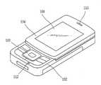
도 2는 본 발명에 따른 제2바디가 세로방향으로 위치된 상태를 나타낸 정면도이다.2 is a front view showing a state in which the second body according to the present invention is located in the longitudinal direction.
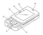
도 3은 본 발명에 따른 제2바디가 가로방향으로 위치된 상태를 나타낸 정면도이다.3 is a front view showing a state in which the second body according to the present invention is located in the horizontal direction.
도 4는 본 발명에 따른 제1바디의 상부 케이스의 내면을 나타낸 사시도이다.Figure 4 is a perspective view showing the inner surface of the upper case of the first body according to the present invention.
도 5는 본 발명에 따른 제1바디의 상부 케이스의 내면을 나타낸 일부 사시도이다.5 is a partial perspective view showing the inner surface of the upper case of the first body according to the present invention.
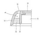
도 6은 본 발명에 따른 제1바디의 상부 케이스의 일부 단면도이다.6 is a partial cross-sectional view of the upper case of the first body according to the present invention.
도 7은 본 발명에 따른 제2레시버의 사시도이다.7 is a perspective view of a second receiver according to the present invention.
도 8은 본 발명에 따른 밀폐부재의 사시도이다.8 is a perspective view of a sealing member according to the present invention.
도 9는 본 발명에 따른 휴대 단말기의 제어부를 나타낸 블럭도이다.9 is a block diagram illustrating a control unit of a mobile terminal according to the present invention.
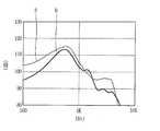
도 10은 본 발명에 따른 휴대 단말기의 레시버를 통해 방출되는 음량을 나타낸 그래프이다.10 is a graph showing the volume emitted through the receiver of the portable terminal according to the present invention.
<도면의 주요부분에 대한 부호의 설명><Description of the symbols for the main parts of the drawings>
10 : 제1바디 20 : 제2바디10: first body 20: second body
24 : 제1사운드 방출부 26 : 제2사운드 방출부24: first sound emitting portion 26: second sound emitting portion
30 : 상부 케이스 32 : 제1사운드 방출홀30: upper case 32: first sound emission hole
34 : 제2사운드 방출홀 36 : 제1레시버34: second sound discharge hole 36: the first receiver
38 : 제2레시버 40 : 가이드부38: second receiver 40: guide part
54 : 밀폐부재54: sealing member
본 발명은 스윙 타입 휴대 단말기에 관한 것으로서, 보다 상세하게는 바디가 가로방향으로 스윙된 상태에서도 통화가 가능하게 하여 사용이 편리한 휴대 단말기에 관한 것이다.The present invention relates to a swing-type portable terminal, and more particularly, to a mobile terminal which is convenient to use by making a call even when the body is swinging in a horizontal direction.
도 1은 종래 기술에 따른 스윙 타입 휴대 단말기의 사시도이다.1 is a perspective view of a swing type portable terminal according to the related art.
종래 기술에 따른 스윙 타입 휴대 단말기는 정보를 입력하는 키버튼 (106)이 구비된 제1바디(102)와, 상기 제1바디(102)에 스윙 가능하게 연결되고 정보를 디스플레이하는 디스플레이(108)를 구비한 제2바디(104)로 구성된다.The swing type portable terminal according to the related art includes a
상기 제1바디(102)에는 통화시 사운드가 입력되는 마이크(112)가 장착되고, 제2바디(104)에는 통화시 사운드가 출력되는 레시버(110)가 세로방향 일단에 장착된다.The
그러나, 상기한 바와 같은 종래 기술에 따른 휴대 단말기는 제2바디(104)의 길이방향 상단에 하나의 레시버(110)가 장착되어 제2바디(104)가 가로방향으로 스 윙되면 레시버(110)가 가로방향 측면에 위치되기 때문에 제2바디(104)가 가로방향으로 스윙된 상태에서는 통화가 불가능하여 사용이 불편한 문제점이 있다.However, in the portable terminal according to the related art as described above, when one
특히, 제2바디(104)가 가로방향으로 스윙된 상태에서 통화 모드시 제2바디(104)를 다시 세로방향으로 스윙시킨 후 통화를 수행해야 되기 때문에 사용이 불편한 문제점이 있다.In particular, there is a problem in that it is inconvenient to use because the
본 발명은 상기한 종래 기술의 문제점을 해결하기 위하여 창출된 것으로서, 본 발명의 목적은 바디의 가로방향 측면에 사운드 방출부를 마련하여 바디가 가로방향으로 스윙된 상태에서도 통화가 가능토록 하여 사용이 편리한 휴대 단말기를 제공하는 데 있다.The present invention was created in order to solve the above problems of the prior art, the object of the present invention is to provide a sound emitting portion on the horizontal side of the body is convenient to use the call even when the body swings in the horizontal direction It is to provide a mobile terminal.
상기한 과제를 실현하기 위한 본 발명의 휴대 단말기는 제1바디와, 상기 제1바디에 스윙 가능하게 연결되는 제2바디와, 상기 제2바디의 세로방향 일단에 형성되어 제2바디가 세로방향으로 위치된 경우 사운드를 방출하는 제1사운드 방출부와, 상기 제2바디의 가로방향 일단에 형성되어 제2바디가 가로방향으로 위치된 경우 사운드를 방출하는 제2사운드 방출부로 구성되는 것을 특징으로 한다.According to an aspect of the present invention, there is provided a portable terminal including a first body, a second body swingably connected to the first body, and a second body formed at one end in a longitudinal direction of the second body. And a first sound emitter for emitting sound when positioned at a second position, and a second sound emitter for emitting sound when the second body is positioned at a horizontal end of the second body and positioned at a horizontal direction. do.
제1사운드 방출부는 상기 제2바디의 세로방향 일측에 형성되는 제1사운드 방출홀과, 상기 제2바디의 내부에 장착되어 상기 제1사운드 방출홀을 통해 방출되는 사운드를 발생시키는 제1레시버로 구성되는 것을 특징으로 한다.The first sound emitting unit includes a first sound emitting hole formed at one side in the longitudinal direction of the second body and a first receiver mounted inside the second body to generate sound emitted through the first sound emitting hole. Characterized in that consists of.
상기 제2사운드 방출부는 상기 제2바디의 세로방향 일측에 형성되는 제2사운 드 방출홀과, 상기 제2바디의 내부에 장착되어 상기 제2사운드 방출홀을 통해 방출되는 사운드를 발생시키는 제2레시버를 포함하여 구성되는 것을 특징으로 한다.The second sound emitting unit includes a second sound emitting hole formed at one side in the longitudinal direction of the second body, and a second mounted inside of the second body to generate sound emitted through the second sound emitting hole. It is characterized by including a receiver.
상기 제2사운드 방출부는 상기 제2레시버에서 발생되는 사운드를 제2사운드 방출홀로 가이드하는 가이드부를 더 포함하는 것을 특징으로 한다.The second sound emitting unit may further include a guide unit for guiding the sound generated by the second receiver to the second sound emitting hole.
상기 사운드 가이드부는 제2바디의 케이스 내면에 형성되는 사운드 통로와, 상기 사운드 통로를 밀폐시켜 사운드 통로로 통과하는 음이 새는 것을 방지하는 밀폐부재로 구성되는 것을 특징으로 한다.The sound guide part may include a sound path formed on the inner surface of the case of the second body and a sealing member sealing the sound path to prevent leakage of sound passing through the sound path.
이하, 첨부된 도면을 참조하여 본 발명에 따른 휴대 단말기의 실시 예를 설명하면 다음과 같다.Hereinafter, an embodiment of a portable terminal according to the present invention will be described with reference to the accompanying drawings.
도 2는 본 발명의 일 실시예에 따른 휴대 단말기의 제2바디가 세로방향으로 위치된 상태를 나타낸 정면도이고, 도 3은 본 발명의 일 실시예에 따른 휴대 단말기의 제2바디가 가로방향으로 스윙된 상태를 나타낸 정면도이다.2 is a front view showing a state in which the second body of the portable terminal according to an embodiment of the present invention is located in the vertical direction, Figure 3 is a second body of the portable terminal according to an embodiment of the present invention in the horizontal direction Front view showing a swinged state.
본 발명에 따른 휴대 단말기는 정보를 입력하는 키들(12,14)이 구비한 제1바디(10)와, 상기 제1바디(10)에 가로방향으로 스윙 가능하게 연결되고 정보를 표시하는 디스플레이(22)가 구비되는 제2바디(20)로 구성된다.According to an embodiment of the present invention, a portable terminal includes a
상기 제1바디(10)와 제2바디(20) 사이에는 스윙모듈(미도시)이 설치되어 제2바디(20)가 제1바디(10)에 대해 상대적으로 스윙되도록 지지한다.A swing module (not shown) is installed between the
상기 제1바디(10)에 설치되는 키들은 제2바디(20)의 스윙 위치에 상관없이 항상 외부로 노출되게 배치되는 제1키들(12)과, 상기 제2바디(20)가 가로방향으로 스윙된 상태일 때 외부로 노출되어 정보를 입력하는 제2키들(14)로 구성된다.Keys installed in the
그리고, 상기 제1바디(10)에는 통화모드시 사운드가 입력되는 마이크(16)가 설치된다.The
도 4는 본 발명의 제2바디의 상부 케이스의 내면을 나타낸 사시도이고, 도 5는 본 발명의 제2바디의 상부 케이스의 내면을 나타낸 일부 사시도이고, 도 6은 본 발명의 상부 케이스의 일부 단면도이다.Figure 4 is a perspective view showing the inner surface of the upper case of the second body of the present invention, Figure 5 is a partial perspective view showing the inner surface of the upper case of the second body of the present invention, Figure 6 is a partial cross-sectional view of the upper case of the present invention to be.
상기 제2바디(20)에는 제2바디(20)의 세로방향 일단에 설치되어 제2바디(20)가 세로방향으로 위치된 경우 사운드를 방출하는 제1사운드 방출부(24)와, 제2바디(20)의 가로방향 일단에 설치되어 제2바디(20)가 가로방향으로 위치된 경우 사운드를 방출하는 제2사운드 방출부(26)로 구성된다.A
상기 제1사운드 방출부(24)는 제2바디(20)의 상부 케이스(30)의 세로방향 일단에 형성되어 사운드가 외부로 방출되는 제1사운드 방출홀(32)과, 상기 제2바디(20)의 내부에 장착되어 제1사운드 방출홀(32)을 통해 방출되는 사운드를 발생시키는 제1레시버(36)로 구성된다.The first
상기 제1레시버(36)는 상부 케이스(30)의 세로방향 중앙측에 형성된 장착부(41)에 장착된다.The
상기 제2사운드 방출부(26)는 제2바디(20)의 가로방향 일단에 형성되어 사운드를 외부로 방출시키는 제2사운드 방출홀(34)과, 상기 제2바디(20)의 내부에 장착되어 상기 제2사운드 방출홀(34)을 통해 방출되는 사운드를 발생시키는 제2레시버(38)와, 상기 제2레시버(38)에서 발생되는 사운드를 제2사운드 방출홀(34)로 가이드하는 가이드부(40)로 구성된다.The
상기 제2사운드 방출홀(34)은 제2바디(20)가 가로방향으로 스윙되면 제2바디(20)의 양쪽 측면 중 상측에 위치되는 측면에 형성된다.The second
상기 제2레시버(38)는 제2바디(20)의 네 모서리 중 어느 한 모서리 부위에 장착된다. 즉, 상기 제1레시버(36)가 제2바디(20)의 일단 중앙에 장착되고, 제2레시버(38)는 제1레시버(36)와 일정 간격을 두고 모서리 부위에 장착된다.The
상기 제2바디(20)의 내면에는 상기 제2레시버(38)가 장착되는 제2레시버 장착부(42)가 형성되고, 상기 제2레시버 장착부(42)에는 제2레시버(38)에서 발생되는 음이 새는 것을 방지함과 아울러 제2레시버(38)를 충격으로부터 보호하는 댐퍼부재(44)가 끼움 결합된다.A second
상기 댐퍼부재(44)는 도 7에 도시된 바와 같이, 우레탄 재질로 형성되는 것이 바람직하고 가이드부(40)와 연통되는 통로(46)가 마련된다.As shown in FIG. 7, the
상기 가이드부(40)는 제2바디(20)의 상부 케이스(30)의 내면에 길이방향으로 형성되고 그 일단은 제2레시버(38)가 장착되는 제2레시버 장착부(42)와 연결되고, 타단은 제2사운드 방출홀(34)과 연결된다.The
이러한 가이드부(40)는 상기 제2바디(20)의 내면에 형성되어 디스플레이(22)를 지지하는 지지리브(50)와, 제2바디(20)의 상부 케이스(30)의 가장자리에서 연장되는 격벽(52) 사이의 공간으로 형성되는 것이 바람직하다.The
상기 가이드부(40)에는 가이드부(40)를 밀폐하여 가이드부(40)를 통과하는 음이 새는 것을 방지하는 밀폐부재(54)가 장착된다.The
상기 밀폐부재(54)는 도 8에 도시된 바와 같이, 상기 가이드부(40)에 끼움 결합되도록 일정 길이를 갖는 바 타입으로 형성되고 그 일면은 격벽(52)에 밀착되고, 그 타면은 지지리브(50)에 밀착되어 가이드부(40)를 밀폐시킨다. 이러한 밀폐부재(54)는 우레탄 재질로 형성되는 것이 바람직하다.As shown in FIG. 8, the sealing
상기한 바와 같이 구성되는 본 발명의 일 실시예에 따른 휴대 단말기의 작용을 다음에서 설명한다.The operation of the portable terminal according to an embodiment of the present invention configured as described above will be described below.
도 9는 본 발명에 따른 휴대 단말기의 제어부를 나타낸 블럭도이다.9 is a block diagram illustrating a control unit of a mobile terminal according to the present invention.
먼저, 제2바디(20)가 세로방향으로 위치된 상태에서 통화모드시 제2바디(20)의 현 위치를 감지하는 위치 감지부(62)로부터 인가되는 신호에 따라 제어부(60)는 제1레시버(36)로 신호를 전달한다. 그러면, 상기 제1레시버(36)에서 소리가 발생되고, 제1레시버(36)에서 발생되는 소리는 제2바디(20)의 세로방향 일단에 형성된 제1사운드 방출홀(32)을 통해 외부로 방출된다.First, in response to a signal applied from the
그리고, 제2바디(20)가 스윙되어 가로방향으로 위치된 상태에서 통화모드시 위치 감지부(62)로부터 인가되는 신호에 따라 제어부(60)는 제2바디(20)가 가로방향으로 스윙된 상태인 것으로 판단하여 제2레시버(38)로 신호를 전달한다.Then, in the state where the
그러면, 상기 제2레시버(38)에서 사운드가 발생되고, 상기 제2레시버(38)에서 발생된 사운드는 가이드부(40)를 통해 제2바디(20)의 가로방향 일단에 형성된 제2사운드 방출홀(34)을 통해 외부로 방출된다.Then, a sound is generated in the
이와 같이, 제2바디(20)가 세로방향으로 위치된 경우에는 제2바디(20)의 세로방향 일단에 형성된 제1레시버 방출홀(32)을 통해 사운드가 방출되고, 제2바디(20)가 가로방향으로 위치된 경우에는 제2바디(20)의 가로방향 일단에 형성된 제 2레시버 방출홀(34)을 통해 사운드가 발생되기 때문에 제2바디(20)의 현재 위치에 상관없이 통화모드를 구현할 수 있다.As such, when the
도 10은 본 발명의 일 실시예에 따른 제1사운드 방출홀을 통해 방출되는 음량과 제2사운드 방출홀을 통해 방출되는 음량을 비교한 그래프이다.10 is a graph comparing the volume emitted through the first sound emitting hole and the volume emitted through the second sound emitting hole according to an embodiment of the present invention.
도 10의 그래프에 나타낸 바와 같이, 제1레시버(36)에서 발생된 사운드가 직접 제1사운드 방출홀(32)을 통해 방출되는 음량을 나타낸 그래프(P)와 제2레시버(38)에서 발생된 사운드가 가이드부(40)를 통과하여 제2사운드 방출홀(34)을 통해 방출되는 음량을 나타낸 그래프(Q)를 비교하면 제2사운드 방출홀(34)을 통해 방출되는 음량이 제1사운드 방출홀(32)을 통해 방출되는 음량의 80% 정도의 성능을 발휘한다. 즉, 가이드부(40)를 통과하면서 발생되는 손실이 비교적 크기 않기 때문에 제2사운드 방출홀(34)을 통해 방출되는 사운드를 충분히 통신모드에 사용이 가능하다.As shown in the graph of FIG. 10, in the graph P and the
상기한 바와 같이 구성되고 작용되는 본 발명에 따른 휴대 단말기는 제2바디의 세로방향 일단에 제1사운드 방출홀을 형성하고, 제2바디의 가로방향 일단에 제2사운드 방출홀을 형성하여, 제2바디가 세로방향으로 위치된 경우에는 제1레시버에서 발생된 사운드가 제1사운드 방출홀을 통해 외부로 방출되고 제2바디가 가로방향으로 위치된 경우에는 제2레시버에서 발생된 사운드가 제2사운드 방출홀을 통해 방출되도록 함으로써, 제2바디의 스윙 위치에 상관없이 통신모드를 구현할 수 있어 사용이 편리하다.The portable terminal according to the present invention constructed and operated as described above forms a first sound emission hole in one longitudinal direction of the second body and a second sound emission hole in one horizontal direction of the second body. When the second body is located in the vertical direction, the sound generated by the first receiver is emitted to the outside through the first sound emission hole, and when the second body is located in the horizontal direction, the sound generated by the second receiver is By discharging through the second sound emitting hole, it is possible to implement a communication mode regardless of the swing position of the second body is convenient to use.
Claims (13)
Translated fromKoreanPriority Applications (7)
| Application Number | Priority Date | Filing Date | Title |
|---|---|---|---|
| KR1020060054086AKR101134799B1 (en) | 2006-06-15 | 2006-06-15 | Portable terminal |
| JP2007098254AJP4546987B2 (en) | 2006-06-15 | 2007-04-04 | Portable terminal and speaker control method thereof |
| US11/761,200US8060160B2 (en) | 2006-06-15 | 2007-06-11 | Mobile terminal having speaker control and method of use |
| DE602007011689TDE602007011689D1 (en) | 2006-06-15 | 2007-06-14 | Mobile terminal with loudspeaker control and method of use |
| CN2007101270031ACN101090408B (en) | 2006-06-15 | 2007-06-14 | Mobile terminal having speaker control and method of use |
| EP07011722AEP1868357B1 (en) | 2006-06-15 | 2007-06-14 | Mobile terminal having speaker control and method of use |
| AT07011722TATE494722T1 (en) | 2006-06-15 | 2007-06-14 | MOBILE TERMINAL WITH SPEAKER CONTROL AND METHOD OF USE |
Applications Claiming Priority (1)
| Application Number | Priority Date | Filing Date | Title |
|---|---|---|---|
| KR1020060054086AKR101134799B1 (en) | 2006-06-15 | 2006-06-15 | Portable terminal |
Publications (2)
| Publication Number | Publication Date |
|---|---|
| KR20070119448A KR20070119448A (en) | 2007-12-20 |
| KR101134799B1true KR101134799B1 (en) | 2012-04-13 |
Family
ID=38521464
Family Applications (1)
| Application Number | Title | Priority Date | Filing Date |
|---|---|---|---|
| KR1020060054086AExpired - Fee RelatedKR101134799B1 (en) | 2006-06-15 | 2006-06-15 | Portable terminal |
Country Status (7)
| Country | Link |
|---|---|
| US (1) | US8060160B2 (en) |
| EP (1) | EP1868357B1 (en) |
| JP (1) | JP4546987B2 (en) |
| KR (1) | KR101134799B1 (en) |
| CN (1) | CN101090408B (en) |
| AT (1) | ATE494722T1 (en) |
| DE (1) | DE602007011689D1 (en) |
Families Citing this family (23)
| Publication number | Priority date | Publication date | Assignee | Title |
|---|---|---|---|---|
| JP2008076818A (en)* | 2006-09-22 | 2008-04-03 | Fujitsu Ltd | Mobile terminal device |
| JP2009290346A (en)* | 2008-05-27 | 2009-12-10 | Panasonic Electric Works Co Ltd | Panel speaker apparatus |
| US20120027224A1 (en)* | 2010-07-29 | 2012-02-02 | Sony Ericsson Mobile Communications Ab | Acoustic System for Slide-Type Mobile Device |
| US9313565B2 (en) | 2010-07-29 | 2016-04-12 | Nec Corporation | Portable terminal device having sound emission hole which changes orientation based on rotation of casing about biaxial hinge |
| US9294840B1 (en)* | 2010-12-17 | 2016-03-22 | Logitech Europe S. A. | Ease-of-use wireless speakers |
| US20120213397A1 (en)* | 2011-02-22 | 2012-08-23 | Crotts Randel L | Portable Speaker Apparatus |
| US8938312B2 (en) | 2011-04-18 | 2015-01-20 | Sonos, Inc. | Smart line-in processing |
| USD681603S1 (en)* | 2011-04-22 | 2013-05-07 | Samsung Electronics Co., Ltd. | Mobile terminal speaker |
| USD681006S1 (en)* | 2011-04-22 | 2013-04-30 | Samsung Electronics Co., Ltd. | Mobile terminal speaker |
| US9042556B2 (en) | 2011-07-19 | 2015-05-26 | Sonos, Inc | Shaping sound responsive to speaker orientation |
| KR101910839B1 (en)* | 2011-11-07 | 2018-10-24 | 삼성전자주식회사 | Electronic device having acoustic apparatus |
| US8879761B2 (en) | 2011-11-22 | 2014-11-04 | Apple Inc. | Orientation-based audio |
| CN104717351B (en)* | 2013-12-16 | 2019-03-15 | 中兴通讯股份有限公司 | Terminal audio frequency channel processing method, device and terminal |
| CN105357365A (en)* | 2015-09-28 | 2016-02-24 | 联想(北京)有限公司 | Information processing method and electronic equipment |
| TWI583208B (en)* | 2015-10-15 | 2017-05-11 | 宏碁股份有限公司 | Speaker module and electronic device using the same |
| CN106686203A (en)* | 2016-07-11 | 2017-05-17 | 乐视控股(北京)有限公司 | Method for improving terminal communication quality and mobile terminal |
| JP6746420B2 (en)* | 2016-07-29 | 2020-08-26 | キヤノン株式会社 | Strobe unit and imaging device |
| KR102644176B1 (en) | 2016-11-09 | 2024-03-07 | 삼성전자주식회사 | Electronic device |
| KR102386285B1 (en)* | 2017-09-08 | 2022-04-14 | 삼성전자주식회사 | Method for controlling audio outputs by applications respectively through earphone and electronic device for the same |
| CN112369000B (en) | 2018-07-16 | 2023-08-29 | Oppo广东移动通信有限公司 | Shell assembly and electronic equipment |
| KR102562818B1 (en)* | 2018-09-12 | 2023-08-02 | 삼성전자주식회사 | Electronic device with sealing structure |
| CN113438341B (en)* | 2020-01-22 | 2024-08-27 | 华为技术有限公司 | Method and terminal for realizing stereo output |
| WO2024039012A1 (en)* | 2022-08-19 | 2024-02-22 | 삼성전자 주식회사 | Electronic device comprising speaker |
Citations (2)
| Publication number | Priority date | Publication date | Assignee | Title |
|---|---|---|---|---|
| JP2006019910A (en) | 2004-06-30 | 2006-01-19 | Matsushita Electric Ind Co Ltd | Mobile device |
| WO2006038499A1 (en)* | 2004-10-01 | 2006-04-13 | Sharp Kabushiki Kaisha | Mobile information terminal |
Family Cites Families (16)
| Publication number | Priority date | Publication date | Assignee | Title |
|---|---|---|---|---|
| US6321070B1 (en)* | 1998-05-14 | 2001-11-20 | Motorola, Inc. | Portable electronic device with a speaker assembly |
| GB2359177A (en)* | 2000-02-08 | 2001-08-15 | Nokia Corp | Orientation sensitive display and selection mechanism |
| US6819946B2 (en)* | 2002-10-04 | 2004-11-16 | Sony Ericsson Mobile Communications Ab | Apparatus and method for controlling source of sound emitted from a mobile terminal |
| JP3961397B2 (en) | 2002-10-29 | 2007-08-22 | 京セラ株式会社 | Mobile terminal device |
| JP2004336091A (en) | 2003-04-30 | 2004-11-25 | Nec Corp | Foldable mobile communication apparatus |
| JP4230847B2 (en)* | 2003-07-11 | 2009-02-25 | 株式会社東芝 | Mobile terminal device |
| US8155718B2 (en) | 2003-09-03 | 2012-04-10 | Samsung Electronics Co., Ltd. | Sliding/hinge apparatus for sliding/rotating type mobile terminals |
| KR100595705B1 (en) | 2003-12-10 | 2006-06-30 | 엘지전자 주식회사 | Sound output reinforcement device of portable terminal |
| KR100608731B1 (en) | 2003-12-22 | 2006-08-04 | 엘지전자 주식회사 | Swivel handset and call method using same |
| JP4281110B2 (en)* | 2004-02-12 | 2009-06-17 | 日本電気株式会社 | Sound guide structure for mobile phones |
| JP3984968B2 (en)* | 2004-03-30 | 2007-10-03 | 埼玉日本電気株式会社 | Electronic communication equipment |
| JP2006019925A (en)* | 2004-06-30 | 2006-01-19 | Sharp Corp | Portable information terminal, opening / closing method thereof, and display method thereof |
| KR100663542B1 (en)* | 2004-07-30 | 2007-01-02 | 삼성전자주식회사 | Sliding swing device for portable device |
| JP2006067386A (en)* | 2004-08-27 | 2006-03-09 | Ntt Docomo Inc | Mobile terminal device |
| KR100689486B1 (en)* | 2004-10-18 | 2007-03-02 | 삼성전자주식회사 | Speaker device of clamshell portable terminal using resonance space |
| US7809414B2 (en)* | 2005-12-14 | 2010-10-05 | Sharp Kabushiki Kaisha | Portable information terminal, opening/closing operation method, and display method |
- 2006
- 2006-06-15KRKR1020060054086Apatent/KR101134799B1/ennot_activeExpired - Fee Related
- 2007
- 2007-04-04JPJP2007098254Apatent/JP4546987B2/ennot_activeExpired - Fee Related
- 2007-06-11USUS11/761,200patent/US8060160B2/ennot_activeExpired - Fee Related
- 2007-06-14DEDE602007011689Tpatent/DE602007011689D1/enactiveActive
- 2007-06-14ATAT07011722Tpatent/ATE494722T1/ennot_activeIP Right Cessation
- 2007-06-14CNCN2007101270031Apatent/CN101090408B/ennot_activeExpired - Fee Related
- 2007-06-14EPEP07011722Apatent/EP1868357B1/ennot_activeNot-in-force
Patent Citations (2)
| Publication number | Priority date | Publication date | Assignee | Title |
|---|---|---|---|---|
| JP2006019910A (en) | 2004-06-30 | 2006-01-19 | Matsushita Electric Ind Co Ltd | Mobile device |
| WO2006038499A1 (en)* | 2004-10-01 | 2006-04-13 | Sharp Kabushiki Kaisha | Mobile information terminal |
Also Published As
| Publication number | Publication date |
|---|---|
| CN101090408A (en) | 2007-12-19 |
| DE602007011689D1 (en) | 2011-02-17 |
| CN101090408B (en) | 2012-05-30 |
| EP1868357A2 (en) | 2007-12-19 |
| JP4546987B2 (en) | 2010-09-22 |
| EP1868357A3 (en) | 2008-02-13 |
| EP1868357B1 (en) | 2011-01-05 |
| JP2007336517A (en) | 2007-12-27 |
| ATE494722T1 (en) | 2011-01-15 |
| US8060160B2 (en) | 2011-11-15 |
| KR20070119448A (en) | 2007-12-20 |
| US20070291961A1 (en) | 2007-12-20 |
Similar Documents
| Publication | Publication Date | Title |
|---|---|---|
| KR101134799B1 (en) | Portable terminal | |
| US5493690A (en) | Foldable portable telephone set | |
| KR100862294B1 (en) | Mobile terminal and sound guide attached to it | |
| KR20220066871A (en) | Home appliance having voice recognizing function | |
| JP5104056B2 (en) | Sound hole waterproofing and drainage structure for portable electronic devices | |
| JP2021089333A (en) | Sound emission device and electronic keyboard instrument | |
| JP3989804B2 (en) | Speaker built-in computer, portable computer, and method of assembling portable computer | |
| US8160289B2 (en) | Speaker with auxiliary air hole | |
| CA2552665A1 (en) | Handheld electronic device having offset sound openings | |
| JP2013126125A (en) | Audio device | |
| KR102415111B1 (en) | Transmitter for musical instrument and its mode switching method | |
| US11451902B1 (en) | Speaker with vented resonator | |
| JP2020064147A (en) | Keyboard musical instrument | |
| JPH06214569A (en) | Keyboard device of electronic musical instrument | |
| JP2021012400A (en) | Keyboard instrument | |
| JP2008028595A (en) | Buzzer device, and portable electronic equipment with same | |
| JP4417188B2 (en) | Mobile device | |
| US20230175881A1 (en) | Airtight-level sensor and electronic device including the same | |
| JP5151225B2 (en) | Game machine | |
| KR20070071230A (en) | Speaker and mobile terminal having same | |
| KR100568208B1 (en) | Portable computer | |
| JP2001156899A (en) | Communication equipment | |
| KR20080037146A (en) | Folder type portable terminal with improved speaker sound | |
| KR200351702Y1 (en) | Fire alarm bell cover with opened sound source | |
| JP2018019297A (en) | Actuator speaker |
Legal Events
| Date | Code | Title | Description |
|---|---|---|---|
| PA0109 | Patent application | St.27 status event code:A-0-1-A10-A12-nap-PA0109 | |
| PG1501 | Laying open of application | St.27 status event code:A-1-1-Q10-Q12-nap-PG1501 | |
| PN2301 | Change of applicant | St.27 status event code:A-3-3-R10-R13-asn-PN2301 St.27 status event code:A-3-3-R10-R11-asn-PN2301 | |
| R18-X000 | Changes to party contact information recorded | St.27 status event code:A-3-3-R10-R18-oth-X000 | |
| R18-X000 | Changes to party contact information recorded | St.27 status event code:A-3-3-R10-R18-oth-X000 | |
| A201 | Request for examination | ||
| PA0201 | Request for examination | St.27 status event code:A-1-2-D10-D11-exm-PA0201 | |
| D13-X000 | Search requested | St.27 status event code:A-1-2-D10-D13-srh-X000 | |
| D14-X000 | Search report completed | St.27 status event code:A-1-2-D10-D14-srh-X000 | |
| E902 | Notification of reason for refusal | ||
| PE0902 | Notice of grounds for rejection | St.27 status event code:A-1-2-D10-D21-exm-PE0902 | |
| E13-X000 | Pre-grant limitation requested | St.27 status event code:A-2-3-E10-E13-lim-X000 | |
| P11-X000 | Amendment of application requested | St.27 status event code:A-2-2-P10-P11-nap-X000 | |
| P13-X000 | Application amended | St.27 status event code:A-2-2-P10-P13-nap-X000 | |
| E701 | Decision to grant or registration of patent right | ||
| PE0701 | Decision of registration | St.27 status event code:A-1-2-D10-D22-exm-PE0701 | |
| GRNT | Written decision to grant | ||
| PR0701 | Registration of establishment | St.27 status event code:A-2-4-F10-F11-exm-PR0701 | |
| PR1002 | Payment of registration fee | St.27 status event code:A-2-2-U10-U11-oth-PR1002 Fee payment year number:1 | |
| PG1601 | Publication of registration | St.27 status event code:A-4-4-Q10-Q13-nap-PG1601 | |
| PR1001 | Payment of annual fee | St.27 status event code:A-4-4-U10-U11-oth-PR1001 Fee payment year number:4 | |
| PN2301 | Change of applicant | St.27 status event code:A-5-5-R10-R13-asn-PN2301 St.27 status event code:A-5-5-R10-R11-asn-PN2301 | |
| FPAY | Annual fee payment | Payment date:20160324 Year of fee payment:5 | |
| PR1001 | Payment of annual fee | St.27 status event code:A-4-4-U10-U11-oth-PR1001 Fee payment year number:5 | |
| FPAY | Annual fee payment | Payment date:20170324 Year of fee payment:6 | |
| PR1001 | Payment of annual fee | St.27 status event code:A-4-4-U10-U11-oth-PR1001 Fee payment year number:6 | |
| LAPS | Lapse due to unpaid annual fee | ||
| PC1903 | Unpaid annual fee | St.27 status event code:A-4-4-U10-U13-oth-PC1903 Not in force date:20180403 Payment event data comment text:Termination Category : DEFAULT_OF_REGISTRATION_FEE | |
| PC1903 | Unpaid annual fee | St.27 status event code:N-4-6-H10-H13-oth-PC1903 Ip right cessation event data comment text:Termination Category : DEFAULT_OF_REGISTRATION_FEE Not in force date:20180403 | |
| PN2301 | Change of applicant | St.27 status event code:A-5-5-R10-R13-asn-PN2301 St.27 status event code:A-5-5-R10-R11-asn-PN2301 |