KR101133040B1 - Pump for furnishing with grease - Google Patents
Pump for furnishing with greaseDownload PDFInfo
- Publication number
- KR101133040B1 KR101133040B1KR1020090107780AKR20090107780AKR101133040B1KR 101133040 B1KR101133040 B1KR 101133040B1KR 1020090107780 AKR1020090107780 AKR 1020090107780AKR 20090107780 AKR20090107780 AKR 20090107780AKR 101133040 B1KR101133040 B1KR 101133040B1
- Authority
- KR
- South Korea
- Prior art keywords
- chamber
- grease
- housing
- piston
- flow path
- Prior art date
- Legal status (The legal status is an assumption and is not a legal conclusion. Google has not performed a legal analysis and makes no representation as to the accuracy of the status listed.)
- Active
Links
Images


Classifications
- F—MECHANICAL ENGINEERING; LIGHTING; HEATING; WEAPONS; BLASTING
- F16—ENGINEERING ELEMENTS AND UNITS; GENERAL MEASURES FOR PRODUCING AND MAINTAINING EFFECTIVE FUNCTIONING OF MACHINES OR INSTALLATIONS; THERMAL INSULATION IN GENERAL
- F16N—LUBRICATING
- F16N13/00—Lubricating-pumps
- F16N13/02—Lubricating-pumps with reciprocating piston
- F—MECHANICAL ENGINEERING; LIGHTING; HEATING; WEAPONS; BLASTING
- F16—ENGINEERING ELEMENTS AND UNITS; GENERAL MEASURES FOR PRODUCING AND MAINTAINING EFFECTIVE FUNCTIONING OF MACHINES OR INSTALLATIONS; THERMAL INSULATION IN GENERAL
- F16N—LUBRICATING
- F16N23/00—Special adaptations of check valves
- F—MECHANICAL ENGINEERING; LIGHTING; HEATING; WEAPONS; BLASTING
- F16—ENGINEERING ELEMENTS AND UNITS; GENERAL MEASURES FOR PRODUCING AND MAINTAINING EFFECTIVE FUNCTIONING OF MACHINES OR INSTALLATIONS; THERMAL INSULATION IN GENERAL
- F16N—LUBRICATING
- F16N3/00—Devices for supplying lubricant by manual action
- F16N3/10—Devices for supplying lubricant by manual action delivering grease
Landscapes
- Engineering & Computer Science (AREA)
- General Engineering & Computer Science (AREA)
- Mechanical Engineering (AREA)
- Details Of Reciprocating Pumps (AREA)
- Reciprocating Pumps (AREA)
Abstract
Translated fromKoreanDescription
Translated fromKorean본 발명은 설비에 그리스를 공급하는 그리스 공급장치용 펌프에 관한 것으로, 더욱 상세하게는 별도의 그리스 보충용 용기없이 그리스가 담겨진 대형 드럼에 직접 펌프를 삽입하여 그리스를 토출할 수 있도록 된 그리스 공급장치용 펌프에 관한 것이다.The present invention relates to a grease supply pump for supplying grease to a plant, and more particularly, to a grease supply apparatus capable of discharging grease by inserting a pump directly into a large drum containing grease without a separate grease replenishment container. It is about a pump.
일반적으로 그리스 공급장치용 펌프는 에어로 작동하는 에어식 펌프와 전기모터에 의해 작동하는 전기식 펌프 두 가지로 나눌 수 있다.In general, a pump for a grease supply can be divided into an air operated pump and an electric pump operated by an electric motor.
하지만 전기식 펌프는 토출량 및 토출압력이 작기 때문에 많이 사용되고 있지 않고 상대적으로 토출량 및 토출압력이 큰 에어식 펌프가 주로 사용되고 있다.However, the electric pump is not used much because the discharge amount and the discharge pressure is small, and the air pump having a relatively large discharge amount and the discharge pressure is mainly used.
종래기술에 따른 그리스 공급장치용 전기식 펌프의 요부는 도 8에 도시된 바와 같이 그리스 통에 길이방향으로 연장되는 피스톤(10)과, 상기 피스톤(10)에 슬라이딩되는 피스톤홀더(12) 및 체크벨브(14)로 이루어진다.The main part of the electric pump for the grease supply apparatus according to the prior art, as shown in Figure 8, the
상기 그리스 공급장치용 펌프의 작동은 도 9에 도시된 바와 같이 피스톤(10)이 하강하면서 피스톤홀더(12)에 형성된 측면의 그리스 유입부(16)를 통하여 그리 스가 유입되고, 이렇게 유입된 그리스는 피스톤의 소경부(18)를 통하여 유로를 따라 체크밸브(14)의 상류까지 이동한다.The operation of the pump for the grease supply device is grease is introduced through the
다음으로 도 10에 도시된 바와 같이 피스톤(10)이 사점을 지나 역전되어 상승하면 그리스 유입부(16)가 막히면서 유로에 잔존해 있는 그리스를 가압된다. 따라서 가압된 그리스는 탄성설치된 체크밸브(14)의 탄성력을 극복하고 하류측으로 유출되어 설비에 공급된다.Next, as shown in FIG. 10, when the
이와 같은 종래기술에 따른 전기식 펌프는 하나의 체크밸브만 설치되어 있으므로 그리스를 공급하기 위해서는 피스톤의 왕복속도가 빨라야 할 뿐만 아니라 역류 또한 효과적으로 차단하지 못하는 문제점이 있다.Since the electric pump according to the related art is provided with only one check valve, the reciprocating speed of the piston must not only be fast to supply grease, but also there is a problem that the back flow cannot be effectively blocked.
또한 종래기술에 따른 전기식펌프는 피스톤의 헤드부가 피스톤과 고정핀으로 연결되어 헤드부가 압력을 받을 경우 피스톤 고정핀이 손상되는 문제점이 있다.In addition, the electric pump according to the related art has a problem in that the piston fixing pin is damaged when the head of the piston is connected to the piston and the fixing pin so that the head receives the pressure.
아울러 전기식펌프는 모터를 정지시키지 않는 한 그리스가 계속 토출되므로 배관의 압력이 상승하여 배관이 파손되거나 모터가 계속적으로 공회전하여 전력소모될 뿐 아니라 심지어 모터가 소손되는 문제점이 있다.In addition, since the electric pump is continuously discharged grease unless the motor is stopped, the pressure of the pipe is increased, the pipe is damaged or the motor continues to idle, power consumption, there is a problem that even the motor is burned out.
따라서 본 발명은 상기와 같은 문제점을 해결하기 위하여 안출된 것으로, 체크밸브를 다단계로 설치하여 피스톤의 왕복동작의 회수와 속도에 관계없이 안정적으로 그리스의 흡입 및 토출을 제어할 수 있도록 된 그리스 공급장치용 펌프를 제공하는 데 목적이 있다.Therefore, the present invention has been made to solve the above problems, the grease supply device that can be installed in a multi-stage check valve to control the suction and discharge of grease stably regardless of the number and speed of the reciprocating operation of the piston The purpose is to provide a pump.
또한 본 발명은 그리스가 실린더 내부에 형성된 관로를 통하여 이송되도록 함으로써 압력상승에 따른 누유를 방지할 수 있도록 된 그리스 공급장치용 펌프를 제공하는 데 목적이 있다.In addition, an object of the present invention is to provide a pump for a grease supply device that is capable of preventing the oil leakage due to the pressure rise by allowing the grease to be transported through the pipeline formed inside the cylinder.
아울러 본 발명은 캠과 피스톤의 체결시 고정핀을 이용하지 않고 캠을 이용하여 필요에 따라 스크로크를 가변시킬 수 있도록 된 그리스 공급장치용 펌프를 제공하는 데 목적이 있다.In addition, an object of the present invention is to provide a pump for a grease supply device that is able to vary the stroke as necessary by using the cam without using a fixing pin when the cam and the piston is fastened.
또한 본 발명은 캠의 구멍에 삽입되는 핸들이 부착된 축을 구비하여 비상시 인력으로 그리스를 공급할 수 있도록 된 그리스 공급장치용 펌프를 제공하는 데 목적이 있다.It is also an object of the present invention to provide a pump for a grease supply device, which has a shaft with a handle inserted into a hole of a cam so that grease can be supplied by an emergency force.
상기의 목적은, 내주면을 따라 피스톤이 슬라이딩될 수 있도록 중공(中空)형상으로 구비되고 중앙에 피스톤이 관통될 수 있도록 관통구가 형성된 플랜지가 상부에 형성되고 하부가 개방되며, 상기 내주면에는 내경이 상기 내주면보다 큰 제1실, 제2실 및 제3실이 순차적으로 형성되며, 상기 플랜지의 일측에는 상기 제1실과 연통되어 그리스가 배출되는 배출구가 형성되며, 상기 제3실에는 그리스가 유입될 수 있도록 측면에 유입구가 형성된 하우징과; 상기 하우징의 내주면과 밀착되고, 내부에 그리스가 유통될 수 있도록 상단이 상기 하우징의 제1실과 연통되도록 형성된 유로와, 상기 유로의 상단에 형성된 상기 유로보다 내경이 큰 제4실과, 상기 유로의 하단에 형성되어 상기 소경부와 상기 하우징의 내주면 사이의 간극과 연통되는 연통구와, 상부에 걸림단이 형성된 대경부와, 상기 대경부에서 하방으로 연장형성되되, 상기 하우징의 내주면과 소정의 간극을 갖도록 형성되며, 하단에 상기 하우징의 제1실에 수용되는 스톱퍼가 형성된 소경부를 갖는 피스톤과; 디스크형상의 캠과, 상기 캠의 일측면에 원주방향으로 따라 연장형성되며 상기 피스톤의 걸림단)이 끼워져 슬라이딩될 수 있도록 중앙이 원주방향을 따라 요입부가 형성된 캠링과, 상기 캠의 중심을 기준으로 편심된 위치에 축이 삽입될 수 있도록 형성된 복수의 구멍과, 상기 복수의 구멍 중 하나의 구멍에 삽입될 수 있도록 구비된 축과, 상기 축을 회전시키는 구동원으로 이루어지는 구동수단과; 상기 유로에 형성된 상기 제4실과, 상기 유로의 중간에 형성된 제5실에 설치된 역류방지수단과; 상기 하우징의 제3실에 수용되고, 상기 피스톤의 스톱파 상부에 설치되며, 상하방향으로 관통구가 형성된 평판밸브와; 상기 하우징의 제2실에 승강이 가능하도록 설치되어 상기 피스톤의 스크로크 변화에도 그리스를 원활하게 배출할 수 있도록 구비된 부유체크밸브; 를 포함하는 것을 특징으로 하는 그리스 공급장치용 펌프에 의해 달성된다.
상기 피스톤의 유로의 중간에 상기 유로보다 내경이 큰 제5실이 형성되고, 상기 역류방지수단은 상기 피스톤의 제4실에 설치된 제1체크밸브와; 상기 피스톤의 제5실에 설치된 제2체크밸브를 포함하는 것을 특징으로 한다.
상기 부유체크밸브의 상부에 설치되는 스프링을 더 포함하는 것을 특징으로 한다.
상기 구동원은 전기모터인 것을 특징으로 한다.
상기 구동수단의 축은 단부에 핸들이 설치되어 인력으로도 펌프를 작동시킬 수 있도록 구비된 것을 특징으로 한다.The above object is provided with a hollow shape so that the piston can slide along the inner circumferential surface and a flange having a through hole formed therein so as to allow the piston to penetrate at the center thereof is formed on the upper side and the lower side thereof is opened, and the inner circumferential surface has an inner diameter. A first chamber, a second chamber, and a third chamber larger than the inner circumferential surface are sequentially formed, and a discharge port through which the grease is discharged in communication with the first chamber is formed at one side of the flange, and the grease is introduced into the third chamber. A housing having an inlet formed at a side thereof so as to be provided; A flow path formed in close contact with the inner circumferential surface of the housing and having a top end in communication with the first chamber of the housing so that grease can be distributed therein, a fourth chamber having an inner diameter larger than the flow path formed in the top of the flow path, and a bottom end of the flow path A communication port formed in the communication hole and communicating with a gap between the small diameter portion and the inner circumferential surface of the housing; A piston having a small diameter portion formed at a lower end thereof and having a stopper formed in the first chamber of the housing; A cam having a disk shape, a cam ring extending in the circumferential direction on one side of the cam, and having a concave indentation along the circumferential direction thereof so that the center of the cam is slid and fitted; Drive means comprising a plurality of holes formed to allow the shaft to be inserted at an eccentric position, a shaft provided to be inserted into one of the plurality of holes, and a drive source for rotating the shaft; Backflow preventing means provided in said fourth chamber formed in said flow path and a fifth chamber formed in the middle of said flow path; A flat valve accommodated in a third chamber of the housing, installed on an upper portion of the stop wave of the piston, and having a through hole formed in a vertical direction; A floating check valve installed in the second chamber of the housing to allow the grease to be smoothly discharged even when the piston is changed in stroke; It is achieved by a pump for grease supply, characterized in that it comprises a.
A fifth chamber having an inner diameter larger than that of the flow passage is formed in the middle of the flow passage of the piston, and the backflow preventing means comprises: a first check valve installed in the fourth chamber of the piston; And a second check valve installed in the fifth chamber of the piston.
It is characterized in that it further comprises a spring installed on the upper portion of the floating check valve.
The drive source is characterized in that the electric motor.
The shaft of the drive means is characterized in that the handle is provided at the end is provided so that it can operate the pump even by manpower.
삭제delete
삭제delete
삭제delete
삭제delete
삭제delete
삭제delete
삭제delete
삭제delete
삭제delete
삭제delete
본 발명에 따른 그리스 공급장치용 전기식 펌프는 체크밸브를 다단계로 설치하여 피스톤의 왕복동작의 회수와 속도에 관계없이 안정적으로 그리스의 흡입 및 토출을 제어할 수 있다.The electric pump for grease supplying apparatus according to the present invention can stably control the suction and discharge of grease regardless of the number and speed of the reciprocating motion of the piston by installing a check valve in multiple stages.
또한 본 발명에 따른 그리스 공급장치용 펌프는 그리스가 실린더 내부에 형성된 관로를 통하여 이송되도록 함으로써 압력상승에 따른 누유를 방지할 수 있다.In addition, the pump for the grease supply apparatus according to the present invention can prevent the oil leakage due to the pressure rise by allowing the grease to be transferred through the pipe line formed inside the cylinder.
또한 본 발명에 따른 그리스 공급장치용 전기식 펌프는 아울러 캠과 피스톤의 체결시 고정핀을 이용하지 않고 캠을 이용하므로 모터구동시 피스톤의 스트로크 를 가변시킬 수 있다.In addition, the electric pump for the grease supply apparatus according to the present invention can also vary the stroke of the piston during motor driving because the cam is used without the use of a fixing pin when the cam and the piston are fastened.
또한 본 발명에 따른 그리스 공급장치용 펌프는 캠의 구멍에 삽입되는 핸들이 부착된 축을 구비하여 비상시 인력으로 그리스를 공급할 수 있다.In addition, the grease supply pump according to the present invention has a shaft with a handle inserted into the hole of the cam can supply grease in the emergency personnel.
이하, 본 발명에 따른 그리스 공급장치용 전기식 펌프의 일실시예를 첨부도면을 참조하여 설명하면 다음과 같다.Hereinafter, an embodiment of an electric pump for a grease supply apparatus according to the present invention will be described with reference to the accompanying drawings.
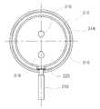
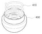
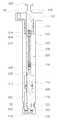
도 1은 본 발명에 따른 그리스 공급장치용 전기식 펌프를 나타내는 단면도이고, 도 2는 본 발명에 따른 그리스 공급장치용 전기식 펌프의 구동수단을 나타내는 정면도이며, 도 3은 본 발명에 따른 부유체크밸브의 형상을 나타내기 위한 사시도이다.1 is a cross-sectional view showing an electric pump for a grease supply apparatus according to the present invention, Figure 2 is a front view showing a drive means of the electric pump for a grease supply apparatus according to the present invention, Figure 3 is a floating check valve of the present invention It is a perspective view for showing a shape.
전기식 펌프는 하우징(100)과, 상기 하우징(100)을 따라 승강하는 피스톤(200)과, 상기 피스톤(200)을 승강시키도록 설치된 구동수단과, 상기 그리스의 유통경로 상에 설치된 적어도 2개 이상의 역류방지수단과, 상기 피스톤(200)에 설치된 평판밸브(500)를 포함한다.The electric pump includes a
하우징(100)은 하부가 개방된 실린더 형상으로서 상부에는 플랜지(102)가 형성되어 있다. 상기 플랜지(102)에는 피스톤(200)이 관통할 수 있도록 관통구(104)가 형성되어 있으며 피스톤(200)의 일측에는 상기 하우징(100)의 내부와 연통되는 배출구(106)가 형성된다. 상기 하우징(100)의 내부에는 내주면보다 내경이 큰 제1실(110), 제2실(112) 및 제3실(114)이 순차적으로 형성된다. 여기서 제1실(110)은 상기 배출구(106)와 연통되도록 형성된다. 또한 상기 하우징(100)의 하부에 형성된 제3실(114)에는 하우징(100)을 반경방향으로 관통하는 별도의 유입구(120)가 형성된다. 여기서 상기 유입구(120)의 테두리부는 하우징(100)의 중심방향으로 돌출된 돌기부(122)가 형성된다. 상기와 같은 하우징(100)은 하부에 형성된 개구(108)와 제3실(114)에 형성된 유입구(120)를 통하여 그리스가 유입되고 하우징(100)의 내부를 따라 상승하여 배출구(106)를 통하여 외부로 배출되게 된다.The
피스톤(200)은 상기 하우징(100)의 내주면을 따라 승강하도록 설치되며 상부에는 구동수단이 형성되어 있다. 상기 피스톤(200)은 하우징(100)의 내주면과 밀착되는 대경부(210)와, 상기 대경부(210)의 하부에 형성되며 상기 하우징(100)의 내주면과 소정의 간극을 이루는 소경부(220)로 이루어진다. 상기 대경부(210)는 내부에 길이방향으로 그리스가 유통될 수 있도록 유로(230)가 형성되어 있다. 상기 유로(230)의 상단에는 상기 하우징(100)의 제1실(110)과 연통되도록 구비되며 상기 유로(230)보다 내경이 큰 제4실(212)이 형성된다. 상기 제4실(212)과 상기 제1실(110) 사이에는 서로 유통될 수 있도록 유통구(214)가 형성된다. 또한 상기 유로(230)의 중간에는 상기 유로(230)보다 내경이 큰 제5실(216)이 형성되어 있다. 또한 상기 유로(230)의 하단에는 상기 소경부(220)와 상기 하우징(100) 내주면 사이의 간극과 연통되는 연통구(222)가 형성된다. 아울러 상기 소경부(220)는 하단에 상기 하우징(110)의 제3실(114)에 수용되는 스톱파(224)가 형성된다. 상기 스톱파(224)는 후술하는 평판밸브(500)의 관통구(502)를 밀폐하게 된다.The
구동수단(300)은 디스크형상의 캠(310)과, 상기 캠(310)의 일측면에 원주방 향으로 따라 연장형성되며 상기 피스톤(200)의 걸림단(226)이 끼워져 슬라이딩될 수 있도록 중앙이 원주방향을 따라 요입부(312)가 형성된 캠링(314)과, 상기 캠(310)의 중심을 기준으로 편심된 위치에 축(320)이 삽입될 수 있도록 형성된 두 개의 구멍(316, 318)과, 상기 두개 의 구멍(316, 318) 중 하나의 구멍에 삽입될 수 있도록 구비된 축(320)과, 상기 축(320)을 회전시키는 구동원으로 이루어진다.The drive means 300 is formed in the disk-
본 실시예에서 구동원은 전기모터로 이루어져 있지만 단부에 핸들(330)이 설치된 축(320)을 구비하여 전원이 인가되지 않는 비상시에는 인력으로도 펌프를 작동시킬 수 있도록 구비된 것이 바람직하다.In this embodiment, the drive source is composed of an electric motor, but the
여기서 상기 축(320)이 끼워지는 구멍(316, 318)에 따라 스트로크가 변하므로 복수의 압력과 양으로 그리스를 공급할 수 있다. 본 실시예에서 개시하지는 않았지만 필요에 따라 구멍(316, 318)의 수를 늘려 다양한 압력과 양의 그리스를 공급할 수 있음은 물론이다.Here, since the stroke changes according to the
평판밸브(500)는 상기 하우징(100)의 제3실(114)에 수용되고 상기 피스톤(200)의 스톱파(224) 상부에 설치되며 상하방향으로 관통구(502)가 형성된다. 상기 평판밸브(500)는 피스톤(200)이 상승하면서 상하방향으로 형성된 관통구(502)를 밀폐함으로 더 이상 그리스가 하우징(100)의 내부로 유입되는 것을 차단하는 동시에 하우징(100) 내부에 있는 그리스를 가압하여 상방으로 밀어낸다.The
역류방지수단은 상기 피스톤의 유로(230)의 중간에 상기 유로(230)보다 내경이 큰 제5실(216)이 형성되고,The reverse flow prevention means has a
상기 역류방지수단은 상기 피스톤(200)의 제4실(212)에 설치된 제1체크밸 브(404)와, 상기 피스톤의 제5실(216)에 설치된 제2체크밸브(408)로 이루어진다.The backflow prevention means includes a
이러한 역류방지수단은 그리스의 유통경로 상에 설치된 적어도 2개 이상 설치됨에 따라 피스톤(200)의 왕복동작의 회수와 속도에 관계없이 안정적으로 그리스의 흡입 및 토출을 제어할 수 있다.The at least two backflow preventing means may be stably controlled to suction and discharge the grease regardless of the number and the speed of the reciprocating operation of the
여기서 제1체크밸브(404) 및 제2체크밸브(408)는 스프링에 의해서 탄성지지되는 볼에 의해 유로가 차단되는 방식이다.Here, the
부유체크밸브(406)는 하우징(100)의 제2실(112)에 승강이 가능하도록 설치된다. 상기 부유체크밸브(406)는 상기 피스톤(200)의 스크로크가 변화하더라도 부유체크밸브(406)가 승강하면서 역류를 방지하므로 그리스를 원활하게 배출할 수 있도록 구비된다.The floating
또한 부유체크밸브(406)는 상부에 스프링(410)이 설치되어 자중뿐만 아니라 탄성력이 작용하여 부유체크밸브(406)가 상승 후 신속하게 귀환할 수 있다.In addition, the floating
이하, 본 발명에 따른 그리스 공급장치용 전기식 펌프의 작동을 설명하면 다음과 같다.Hereinafter, the operation of the electric pump for grease supply apparatus according to the present invention will be described.
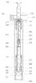
도 4는 본 발명에 따른 펌프의 피스톤이 상승하는 상태를 나타내기 위한 도면이고, 도 5는 본 발명에 따른 펌프의 피스톤이 상승하여 배출구를 통하여 그리스가 배출하기 시작하는 상태를 나타내기 위한 도면이며, 도 6은 본 발명에 따른 펌프의 피스톤이 상승하여 피스톤이 정점에 도달했을 때의 상태를 나타내기 위한 도면이고, 도 7은 본 발명에 따른 펌프의 피스톤이 하강한 후 배출구를 통하여 그리스가 본격적으로 배출되고 있는 상태를 나타내는 도면이다.Figure 4 is a view showing a state in which the piston of the pump according to the present invention rises, Figure 5 is a view showing a state in which the piston of the pump according to the invention rises and the grease is discharged through the outlet. 6 is a view showing the state when the piston of the pump according to the present invention is raised to reach the peak, Figure 7 is a full-scale grease through the outlet after the piston of the pump according to the present invention is lowered It is a figure which shows the state discharged | emitted by the.
도 4에 도시된 바와 같이 피스톤(200)은 상승하면서 상기 평판밸브(500)의 관통구(502)를 밀폐시킨다. 이 때 평판밸브(500)의 관통구(502)가 밀폐되면 개구(108)를 통하여 유입되던 그리스의 공급은 차단되고 측면의 유입구(120)를 통해서만 그리스가 유입된다.As shown in FIG. 4, the
다음으로 피스톤(200)이 계속 상승하면 도 5 내지 도 6에 도시된 바와 같이 상승하면서 상기 평판밸브(500)가 하우징(100)의 유입구(120)에 형성되어 있는 돌기부(122)를 지나서 상승하게 되고, 상승된 평판밸브(500)는 더 이상 개구(108)나 유입구(120)를 통하여 그리스가 유입되지 못하도록 차단하고 동시에 하우징(100)의 내부가 외부와 밀폐되도록 한다. 이와 같이 피스톤(200)이 계속 상승함에 따라 평판밸브(500)의 상부에 위치하고 있는 그리스는 가압되고, 가압된 그리스는 부유체크밸브(406)를 위로 밀어올려 그리스가 부유체크밸브(406)를 지나서 소경부(220)와 하우징(100) 내주면의 간극을 따라 상승하도록 한다. 소경부(220)와 하우징(100) 내주면의 간극을 따라 상승한 그리스는 유로(230)를 따라 이동한 후 배출구(106)를 통하여 외부로 배출된다. 이 때 가압된 그리스는 제2체크밸브(408), 제1체크밸브(404)를 순차적으로 통과한다.Next, when the
또한 상기 피스톤(200)은 상사점을 지난 후 도 7에서 도시된 바와 같이 하강하여도 부유체크밸브(406)로 인하여 하우징(100)의 제3실(114)로 유입되지 않는다. 물론 제1체크밸브(404) 및 제2체크밸브(408) 또한 그리스가 역류하는 것을 방지한다. 이와 같이 여러 단계의 역류방지수단으로 인하여 그리스가 역류하는 것을 완벽하게 방지해 준다.In addition, the
도 1은 본 발명에 따른 그리스 공급장치용 전기식 펌프를 나타내는 단면도이다.1 is a cross-sectional view showing an electric pump for a grease supply device according to the present invention.
도 2는 본 발명에 따른 그리스 공급장치용 전기식 펌프의 구동수단을 나타내는 정면도이다.Figure 2 is a front view showing the drive means of the electric pump for grease supply apparatus according to the present invention.
도 3은 본 발명에 따른 부유체크밸브의 형상을 나타내기 위한 사시도이다.Figure 3 is a perspective view for showing the shape of the floating check valve according to the present invention.
도 4는 본 발명에 따른 펌프의 피스톤이 상승하는 상태를 나타내기 위한 도면이다.Figure 4 is a view for showing a state in which the piston of the pump according to the invention rises.
도 5는 본 발명에 따른 펌프의 피스톤이 상승하여 배출구를 통하여 그리스가 배출하기 시작하는 상태를 나타내기 위한 도면이다.5 is a view showing a state in which the piston of the pump according to the invention rises and the grease is discharged through the outlet.
도 6은 본 발명에 따른 펌프의 피스톤이 상승하여 피스톤이 정점에 도달했을 때의 상태를 나타내기 위한 도면이다.Fig. 6 is a view for showing a state when the piston of the pump according to the present invention is raised to reach the peak.
도 7은 본 발명에 따른 펌프의 피스톤이 하강한 후 배출구를 통하여 그리스가 본격적으로 배출되고 있는 상태를 나타내는 도면이다.7 is a view showing a state in which grease is discharged in earnest through the discharge port after the piston of the pump according to the present invention is lowered.
도 8은 종래기술에 따른 그리스 공급장치용 전기식 펌프를 나타내는 도면이다.8 is a view showing an electric pump for a grease supply device according to the prior art.
도 9는 종래기술에 따른 그리스 공급장치용 전기식 펌프의 피스톤이 하강하는 상태를 나타내는 도면이다.9 is a view showing a state where the piston of the electric pump for grease supply device according to the prior art is lowered.
도 10은 종래기술에 따른 그리스 공급장치용 전기식 펌프의 피스톤이 상승하는 상태를 나타내는 도면이다.10 is a view showing a state in which the piston of the electric pump for a grease supply device according to the prior art rises.
*도면의 주요부분에 대한 부호의 설명** Description of the symbols for the main parts of the drawings *
100 : 하우징 200 : 피스톤100
310 : 캠 500 : 평판밸브310: cam 500: flat valve
Claims (5)
Translated fromKoreanPriority Applications (1)
| Application Number | Priority Date | Filing Date | Title |
|---|---|---|---|
| KR1020090107780AKR101133040B1 (en) | 2009-11-09 | 2009-11-09 | Pump for furnishing with grease |
Applications Claiming Priority (1)
| Application Number | Priority Date | Filing Date | Title |
|---|---|---|---|
| KR1020090107780AKR101133040B1 (en) | 2009-11-09 | 2009-11-09 | Pump for furnishing with grease |
Publications (2)
| Publication Number | Publication Date |
|---|---|
| KR20110051109A KR20110051109A (en) | 2011-05-17 |
| KR101133040B1true KR101133040B1 (en) | 2012-04-04 |
Family
ID=44361534
Family Applications (1)
| Application Number | Title | Priority Date | Filing Date |
|---|---|---|---|
| KR1020090107780AActiveKR101133040B1 (en) | 2009-11-09 | 2009-11-09 | Pump for furnishing with grease |
Country Status (1)
| Country | Link |
|---|---|
| KR (1) | KR101133040B1 (en) |
Families Citing this family (2)
| Publication number | Priority date | Publication date | Assignee | Title |
|---|---|---|---|---|
| CN109707983B (en)* | 2017-10-25 | 2024-04-02 | 郑州奥特科技有限公司 | Grease pump |
| CN109707982B (en)* | 2017-10-25 | 2024-04-02 | 郑州奥特科技有限公司 | Grease pumping device |
Citations (2)
| Publication number | Priority date | Publication date | Assignee | Title |
|---|---|---|---|---|
| JP2009293529A (en) | 2008-06-05 | 2009-12-17 | Furukawa Industrial Machinery Systems Co Ltd | Uniaxial eccentric screw pump |
| JP2010506748A (en) | 2006-09-09 | 2010-03-04 | エレクトロニクス フォー イメージング,インク. | Control of dot size of primer / coating of radiation curable inkjet ink |
- 2009
- 2009-11-09KRKR1020090107780Apatent/KR101133040B1/enactiveActive
Patent Citations (2)
| Publication number | Priority date | Publication date | Assignee | Title |
|---|---|---|---|---|
| JP2010506748A (en) | 2006-09-09 | 2010-03-04 | エレクトロニクス フォー イメージング,インク. | Control of dot size of primer / coating of radiation curable inkjet ink |
| JP2009293529A (en) | 2008-06-05 | 2009-12-17 | Furukawa Industrial Machinery Systems Co Ltd | Uniaxial eccentric screw pump |
Also Published As
| Publication number | Publication date |
|---|---|
| KR20110051109A (en) | 2011-05-17 |
Similar Documents
| Publication | Publication Date | Title |
|---|---|---|
| US9732642B2 (en) | Apparatus for resetting an engine brake using decompressing | |
| US8444398B2 (en) | Pump manifold support | |
| US8454325B2 (en) | Coaxial pumping apparatus with internal power fluid column | |
| MXPA06007926A (en) | High pressure slurry piston pump. | |
| EP3306071A1 (en) | Plunger-type high-pressure pump, and high-pressure assembly and plunger sleeve thereof | |
| PL219756B1 (en) | High pressure pump | |
| KR101133040B1 (en) | Pump for furnishing with grease | |
| RU2256779C1 (en) | Device for oil gas discharge from hole annuity | |
| CN208415140U (en) | Liftable type anti-collision road pile | |
| KR100739504B1 (en) | Portable automatic pump | |
| KR101234992B1 (en) | A water pump capable of being installed and maintained easily | |
| US20060045781A1 (en) | Method and pump apparatus for removing liquids from wells | |
| US4913629A (en) | Wellpoint pumping system | |
| RU2561935C1 (en) | Well sucker-rod pump | |
| KR102206475B1 (en) | Air cylinder oil pump unit for automobile maintenance | |
| KR20190079744A (en) | Hand type water pump | |
| KR101777460B1 (en) | A Air Seal Device of a Vacium Self-priming Pump | |
| KR200447996Y1 (en) | Booster pump | |
| KR101086516B1 (en) | Automatic pumping device for pump | |
| JP2006125209A (en) | Vane pump for CVT | |
| CN101614321A (en) | Method and device for pumping raw material by compressed air with low abrasion | |
| US1410994A (en) | Pump | |
| KR200380118Y1 (en) | automatic ail an inlet pipe aquipment | |
| CN105332875B (en) | A kind of multifunctional water oil dual-purpose electric pump | |
| US20170226825A1 (en) | Submersible pump systems and methods of use |
Legal Events
| Date | Code | Title | Description |
|---|---|---|---|
| A201 | Request for examination | ||
| PA0109 | Patent application | St.27 status event code:A-0-1-A10-A12-nap-PA0109 | |
| PA0201 | Request for examination | St.27 status event code:A-1-2-D10-D11-exm-PA0201 | |
| P11-X000 | Amendment of application requested | St.27 status event code:A-2-2-P10-P11-nap-X000 | |
| P13-X000 | Application amended | St.27 status event code:A-2-2-P10-P13-nap-X000 | |
| R17-X000 | Change to representative recorded | St.27 status event code:A-3-3-R10-R17-oth-X000 | |
| PG1501 | Laying open of application | St.27 status event code:A-1-1-Q10-Q12-nap-PG1501 | |
| PE0902 | Notice of grounds for rejection | St.27 status event code:A-1-2-D10-D21-exm-PE0902 | |
| P11-X000 | Amendment of application requested | St.27 status event code:A-2-2-P10-P11-nap-X000 | |
| P13-X000 | Application amended | St.27 status event code:A-2-2-P10-P13-nap-X000 | |
| E701 | Decision to grant or registration of patent right | ||
| PE0701 | Decision of registration | St.27 status event code:A-1-2-D10-D22-exm-PE0701 | |
| GRNT | Written decision to grant | ||
| PR0701 | Registration of establishment | St.27 status event code:A-2-4-F10-F11-exm-PR0701 | |
| PR1002 | Payment of registration fee | St.27 status event code:A-2-2-U10-U11-oth-PR1002 Fee payment year number:1 | |
| PG1601 | Publication of registration | St.27 status event code:A-4-4-Q10-Q13-nap-PG1601 | |
| FPAY | Annual fee payment | Payment date:20150116 Year of fee payment:4 | |
| PR1001 | Payment of annual fee | St.27 status event code:A-4-4-U10-U11-oth-PR1001 Fee payment year number:4 | |
| FPAY | Annual fee payment | Payment date:20160121 Year of fee payment:5 | |
| PR1001 | Payment of annual fee | St.27 status event code:A-4-4-U10-U11-oth-PR1001 Fee payment year number:5 | |
| P22-X000 | Classification modified | St.27 status event code:A-4-4-P10-P22-nap-X000 | |
| FPAY | Annual fee payment | Payment date:20170406 Year of fee payment:6 | |
| PR1001 | Payment of annual fee | St.27 status event code:A-4-4-U10-U11-oth-PR1001 Fee payment year number:6 | |
| PR1001 | Payment of annual fee | St.27 status event code:A-4-4-U10-U11-oth-PR1001 Fee payment year number:7 | |
| PC1903 | Unpaid annual fee | St.27 status event code:A-4-4-U10-U13-oth-PC1903 Not in force date:20190329 Payment event data comment text:Termination Category : DEFAULT_OF_REGISTRATION_FEE | |
| FPAY | Annual fee payment | Payment date:20191224 Year of fee payment:8 | |
| K11-X000 | Ip right revival requested | St.27 status event code:A-6-4-K10-K11-oth-X000 | |
| PC1903 | Unpaid annual fee | St.27 status event code:N-4-6-H10-H13-oth-PC1903 Ip right cessation event data comment text:Termination Category : DEFAULT_OF_REGISTRATION_FEE Not in force date:20190329 | |
| PR0401 | Registration of restoration | St.27 status event code:A-6-4-K10-K13-oth-PR0401 | |
| PR1001 | Payment of annual fee | St.27 status event code:A-4-4-U10-U11-oth-PR1001 Fee payment year number:8 | |
| R401 | Registration of restoration | ||
| PR1001 | Payment of annual fee | St.27 status event code:A-4-4-U10-U11-oth-PR1001 Fee payment year number:9 | |
| PR1001 | Payment of annual fee | St.27 status event code:A-4-4-U10-U11-oth-PR1001 Fee payment year number:10 | |
| PR1001 | Payment of annual fee | St.27 status event code:A-4-4-U10-U11-oth-PR1001 Fee payment year number:11 | |
| PR1001 | Payment of annual fee | St.27 status event code:A-4-4-U10-U11-oth-PR1001 Fee payment year number:12 | |
| PR1001 | Payment of annual fee | St.27 status event code:A-4-4-U10-U11-oth-PR1001 Fee payment year number:13 | |
| PR1001 | Payment of annual fee | St.27 status event code:A-4-4-U10-U11-oth-PR1001 Fee payment year number:14 |