KR101129227B1 - Daylight guide apparatus for tunnel - Google Patents
Daylight guide apparatus for tunnelDownload PDFInfo
- Publication number
- KR101129227B1 KR101129227B1KR1020100004867AKR20100004867AKR101129227B1KR 101129227 B1KR101129227 B1KR 101129227B1KR 1020100004867 AKR1020100004867 AKR 1020100004867AKR 20100004867 AKR20100004867 AKR 20100004867AKR 101129227 B1KR101129227 B1KR 101129227B1
- Authority
- KR
- South Korea
- Prior art keywords
- light
- tunnel
- inlet
- daylight
- respect
- Prior art date
- Legal status (The legal status is an assumption and is not a legal conclusion. Google has not performed a legal analysis and makes no representation as to the accuracy of the status listed.)
- Expired - Fee Related
Links
Images


Classifications
- F—MECHANICAL ENGINEERING; LIGHTING; HEATING; WEAPONS; BLASTING
- F21—LIGHTING
- F21V—FUNCTIONAL FEATURES OR DETAILS OF LIGHTING DEVICES OR SYSTEMS THEREOF; STRUCTURAL COMBINATIONS OF LIGHTING DEVICES WITH OTHER ARTICLES, NOT OTHERWISE PROVIDED FOR
- F21V7/00—Reflectors for light sources
- F21V7/04—Optical design
- F—MECHANICAL ENGINEERING; LIGHTING; HEATING; WEAPONS; BLASTING
- F21—LIGHTING
- F21V—FUNCTIONAL FEATURES OR DETAILS OF LIGHTING DEVICES OR SYSTEMS THEREOF; STRUCTURAL COMBINATIONS OF LIGHTING DEVICES WITH OTHER ARTICLES, NOT OTHERWISE PROVIDED FOR
- F21V7/00—Reflectors for light sources
- F21V7/0025—Combination of two or more reflectors for a single light source
- F—MECHANICAL ENGINEERING; LIGHTING; HEATING; WEAPONS; BLASTING
- F21—LIGHTING
- F21W—INDEXING SCHEME ASSOCIATED WITH SUBCLASSES F21K, F21L, F21S and F21V, RELATING TO USES OR APPLICATIONS OF LIGHTING DEVICES OR SYSTEMS
- F21W2131/00—Use or application of lighting devices or systems not provided for in codes F21W2102/00-F21W2121/00
- F21W2131/10—Outdoor lighting
- F21W2131/101—Outdoor lighting of tunnels or the like, e.g. under bridges
Landscapes
- Engineering & Computer Science (AREA)
- General Engineering & Computer Science (AREA)
- Non-Portable Lighting Devices Or Systems Thereof (AREA)
Abstract
Translated fromKoreanDescription
Translated fromKorean본 발명은 터널용 주광 유입장치에 관한 것으로서, 더욱 상세하게는 채광한 주광을 이용하여 수십 미터 이상의 길고 넓은 구간 영역에 해당하는 터널 입구부의 경계부를 효과적으로 밝힐 수 있어 터널 입구부의 경계부에 바람직하게 적용될 수 있는 터널용 주광 유입장치에 관한 것이다.The present invention relates to a daylight inflow device for tunnels, and more particularly, it is possible to effectively reveal the boundary of the tunnel entrance corresponding to the long and wide section area of several tens of meters or more by using the mined daylight. It relates to a daylight inlet device for a tunnel.
일반적으로 경제 발전에 따라 사용량이 증가하는 에너지에 대한 보급, 절약 및 보존은 국가 정책의 일환으로 매우 중요시되고 있는데, 최근 화석 연료 에너지의 고갈 우려와 친환경을 위한 이산화탄소 배출량 억제 등의 기조로 에너지 절약의 중요성이 크게 부각되고 있다.In general, the dissemination, saving and preservation of energy, which is increasing in proportion to economic development, is very important as part of the national policy. Significance is of great importance.
한편, 국내의 에너지 사용량 중에서 연중 일정하게 소비되는 적지 않은 양이 실내를 밝히기 위한 조명장치에 사용되고 있는데, 에너지 절약의 기조에 맞춰 주간에는 주광을 이용함으로써 이러한 실내의 조명장치를 대체하기 위한 주광 유입장치가 개발된 바 있다.On the other hand, a small amount of energy consumed throughout the year in the domestic energy consumption is used for the lighting device to illuminate the room, the daylight inflow device to replace the indoor lighting device by using daylight in the daytime in accordance with the trend of energy saving Has been developed.
이와 같은 종래의 주광 유입장치는 건축물의 창문과 실내 천장에 설치되어 주광을 채광하여 실내에 조사하는 광 덕트의 형태를 갖는데, 그 구체적인 구성은 도 1에 도시한 바와 같다.Such a conventional daylight inflow device has a form of a light duct installed in the windows of the building and the ceiling of the room to light daylight by irradiating the room, the specific configuration of which is shown in FIG.
종래의 주광 유입장치는, 창문(W)을 통해 건축물 외측에서 실내 천장까지 이어지는 덕트 형태의 몸체(10), 이 몸체(10)의 건축물 외측 부분에 형성되어 주광이 유입되는 광유입구(20), 광유입구(20)에 대응되게 몸체(10) 내부에 설치되어 주광을 실내 측으로 반사하는 반사경(30) 및 몸체(10)의 실내 측 끝단의 하면에 형성되어 반사경(30)에 의해 반사된 주광을 통과시켜 실내에 조사되게 하는 광배출구(40)로 구성된다.Conventional daylight inlet device is a duct-
이러한 종래의 주광 유입장치는, 대부분 사람이 생활하는 건축물에 사용되도록 개발된 것으로서 광유입구(10)와 광배출구(40) 간의 거리가 수 미터에 불과하고 한정된 협소 공간인 실내를 밝히기 위한 것으로 광유입구(20)를 통해 가능한 많은 주광을 채광하고 광 손실을 최소화하는 반사경(30) 등을 통해 주광을 전달하며 전달된 주광이 하나의 광배출구(40)를 통해 배출되게 하면 족하므로 비교적 간단한 구성으로 이루어진다.Such a conventional daylight inflow device is developed to be used in a building in which most people live, and the distance between the
한편, 자동차가 통행하는 터널에는 그 내부를 밝히기 위한 다량의 조명장치가 구비되는데, 특히 주간에 주광에 의한 밝은 조명도에 적응된 자동차 운전자의 눈이 어두운 터널 내부로 진입하면서 그 어두움에 적응할 때까지 일시적으로 시력을 잃는 현상(블랙홀 현상)을 방지하기 위해 터널 입구부에는 외부의 주광 조명도에 대응되는 매우 밝은 조명도(터널 입구부의 경계부의 조명도) 및 터널 내측으로 진행할수록 점차적으로 완화되는 밝은 조명도(터널 입구부의 이행부와 완화부의 조명도)의 확보가 필수적이다.On the other hand, the tunnel through which the car passes is equipped with a large amount of lighting device to illuminate the interior, especially when the driver's eyes adapted to the bright illumination by daylight enter the dark tunnel and temporarily adapt to the darkness. In order to prevent the loss of vision (black hole phenomenon), the tunnel entrance has a very bright illumination corresponding to the external daylight illumination (illumination at the boundary of the tunnel entrance) and a bright illumination gradually relaxed as it proceeds inside the tunnel. It is essential to secure the lighting degree of the transition part and the relaxation part of the tunnel entrance.
특히 상기 경계부는 그 조명도가 주광의 밝은 조명도에 대응되도록 구비하기 위해 터널 내부의 기본조명도뿐만 아니라 이행부나 완화부의 조명도보다도 높은 조명도를 갖도록 구비되는데, 이러한 요구에 맞추기 위해, 상기 경계부에는 많은 조명장치가 설치되고 주간에는 이 조명장치들이 모두 가동되므로 이에 따른 에너지 소비량이 많은 실정이다.In particular, the boundary portion is provided to have the illumination degree higher than the basic illumination degree inside the tunnel as well as the illumination degree of the transition part or the relaxation part in order to equip the illumination degree to correspond to the bright illumination degree of the main light. Since the lighting devices are installed and operated during the day, the energy consumption is high.
이러한 터널에도 외부의 주광을 채광하여 조사하는 주광 유입장치를 이용하여 에너지를 절약할 필요성이 있으나, 상기 경계부는 수십 미터 이상의 길고 넓은 구간 영역에 해당하고 이를 밝혀야 하므로 사람이 생활하는 실내에 주로 적용되는 전술된 종래의 주광 유입장치를 적용하는 것은 불가능한 문제점이 있다.In such tunnels, it is necessary to save energy by using a daylight inflow device for mining and illuminating outside daylight. However, the boundary part corresponds to a long and wide section of more than a few tens of meters, and thus should be revealed. There is a problem that it is impossible to apply the conventional daylight inflow apparatus described above.
즉, 터널용 주광 유입장치는 주광을 수십 미터의 거리만큼 효과적으로 전달해야 하며, 그 길고 넓은 구간 영역에 해당하는 터널 입구부의 경계부를 적절히 밝혀야 하므로, 하나의 반사경(30)과 광배출구(40)가 구비되어 채광된 주광을 하나의 광배출구(40)로 배출시키는 종래의 주광 유입장치는 터널에 적용될 수 없는 한계가 있다.That is, the tunnel daylight inlet device for the tunnel should effectively transmit the daylight by a distance of several tens of meters, and the boundary portion of the tunnel entrance corresponding to the long and wide section region should be properly identified, so that one reflector 30 and the
특히, 최근 교통량 증가에 대한 부응 및 차량이 소비하는 에너지 절약과 소요시간 절감 목적의 지역 간 이동거리 단축을 달성하기 위해 국내에 설치된 터널의 수는 빠르게 증가하고 있다는 점, 그리고 주간의 주광에 의한 밝은 조명도에 대응되게 터널의 기본조명보다 훨씬 밝은 조명도가 필요한 상기 경계부의 요구 조명도를 감안하면, 에너지 절약을 위한 터널용 주광 유입장치는 그 개발이 시급한 실정이다.In particular, the number of tunnels installed in Korea is increasing rapidly in order to meet the recent increase in traffic volume and to shorten the travel distance between regions in order to save energy and time required by vehicles, and to brighten the daylight Considering the required illuminance of the boundary portion, which requires much brighter illumination than the basic illumination of the tunnel to correspond to the illumination, the development of the daylight inflow device for tunnels for energy saving is urgently needed.
상기한 바와 같은 문제점을 해결하기 위해 본 발명은, 중공부로 유입된 주광을 터널 내측 방향으로 효과적으로 전달하여 터널 입구부의 경계부에 있어서 터널 입구 측의 내부도로뿐만 아니라 터널 내측의 내부도로에도 주광이 효과적으로 조사되도록 함으로써, 터널 입구부의 경계부 전체에 바람직하게 적용될 수 있는 터널광 주광 유입장치를 제공하고자 한다.In order to solve the above problems, the present invention effectively transmits the daylight flowing into the hollow part in the tunnel inward direction so that the daylight is effectively irradiated on the road inside the tunnel as well as the road inside the tunnel at the boundary of the tunnel entrance. By doing so, it is an object of the present invention to provide a tunnel light daylight inflow device that can be preferably applied to the entire boundary of the tunnel inlet.
상기한 바와 같은 과제를 해결하기 위해, 본 발명에 따른 터널용 주광 유입장치는, 터널 입구부의 경계부 천장에 터널의 길이방향을 따라 설치되도록 긴 덕트 형상을 가지며, 내부에 중공부가 형성된 몸체; 상기 중공부로 주광이 유입되도록 상기 몸체의 상기 터널 입구 측 단부에 형성되는 광유입구; 상기 중공부로 유입된 상기 주광이 상기 몸체 하측에 위치한 상기 터널의 내부도로에 조사될 수 있도록 상기 몸체의 하면에 형성되는 복수의 광배출구; 및 상기 복수의 광배출구의 사이에 각각 위치하고 상기 중공부 내부의 상기 주광을 반사하는 복수의 반사부;를 포함하되, 상기 복수의 광배출구는 상기 중공부의 바닥면에 대해 상기 광유입구 측이 낮아지도록 각각 기울어지는 각도(α)를 가지도록 형성되고, 상기 복수의 반사부는 상기 광유입구의 반대측이 낮아지도록 각각 기울어지는 각도(β)를 가지도록 형성된다.In order to solve the problems as described above, the chief daylight inlet device for a tunnel according to the present invention has a long duct shape to be installed along the longitudinal direction of the tunnel in the boundary ceiling of the tunnel inlet, the hollow body therein; A light inlet formed at an end of the tunnel inlet side of the body so that daylight flows into the hollow part; A plurality of light outlets formed on a lower surface of the body so that the chief light flowing into the hollow portion is irradiated onto an inner road of the tunnel located below the body; And a plurality of reflectors disposed between the plurality of light outlets, respectively, for reflecting the main light inside the hollow part, wherein the plurality of light outlets are lowered to the light inlet side with respect to the bottom surface of the hollow part. Each of the plurality of reflection parts is formed to have an inclination angle α, and each of the plurality of reflection parts is formed to have an inclination angle β so that the opposite side of the light inlet is lowered.
상기 복수의 광배출구가 상기 중공부의 바닥면에 대해 기울어진 각도(α)는 각각 3°~ 7°로 구비될 수 있다.Angles α in which the plurality of light outlets are inclined with respect to the bottom surface of the hollow part may be provided at 3 ° to 7 °, respectively.
상기 복수의 반사부가 상기 중공부의 바닥면에 대해 기울어진 각도(β)는 각각 3°~ 7°로 구비될 수 있다.Angles β inclined with respect to the bottom surface of the hollow part of the plurality of reflectors may be provided at 3 ° to 7 °, respectively.
상기 복수의 광배출구가 상기 중공부의 바닥면에 대해 기울어진 각도(α)는 광유입구의 반대측으로 갈수록 감소하도록 형성될 수 있다.The angle of inclination of the plurality of light outlets with respect to the bottom surface of the hollow part may be formed to decrease toward the opposite side of the light inlet.
상기 복수의 반사부가 상기 중공부의 바닥면에 대해 기울어진 각도(β)는 광유입구의 반대측으로 갈수록 증가하도록 형성될 수 있다.An angle β inclined with respect to the bottom surface of the hollow part of the plurality of reflecting parts may be formed to increase toward the opposite side of the light inlet.
상기 복수의 광배출구가 상기 중공부의 바닥면에 대해 기울어진 각도(α)는 광유입구의 반대측으로 갈수록 선형적으로 또는 구간별로 단계적으로 감소하도록 형성될 수 있다.The angle α in which the plurality of light outlets are inclined with respect to the bottom surface of the hollow part may be formed to decrease linearly or step by step toward the opposite side of the light inlet.
상기 복수의 반사부가 상기 중공부의 바닥면에 대해 기울어진 각도(β)는 광유입구의 반대측으로 갈수록 선형적으로 또는 구간별로 단계적으로 증가하도록 형성될 수 있다.An angle β in which the plurality of reflection parts are inclined with respect to the bottom surface of the hollow part may be formed to increase linearly or step by step toward the opposite side of the light inlet.
상기 복수의 반사부는, 상기 중공부 내측의 그 상면에 상기 주광을 반사하도록 설치된 반사부재;를 포함할 수 있다.The plurality of reflection parts may include a reflection member installed to reflect the main light on an upper surface of the inside of the hollow part.
상기 중공부의 천장면은, 상기 내부도로와 평행하게 구비되는 상기 중공부의 바닥면에 대하여 상기 광유입구로부터 상기 몸체의 길이방향을 따라 상기 광유입구의 반대편으로 갈수록 그 높이가 낮아지도록 기울어지게 구비될 수 있다.The ceiling surface of the hollow part may be provided to be inclined so that its height becomes lower toward the opposite side of the light inlet from the light inlet along the longitudinal direction of the body with respect to the bottom surface of the hollow part provided in parallel with the inner road. have.
이러한 본 발명의 터널용 주광 유입장치에 의하면, 몸체의 하면에 길이방향을 따라 광배출구와 반사부를 번갈아 배치하고, 이 광배출구 및 반사부는 각각 광유입구 측 및 광유입구의 반대측이 낮아지도록 기울어지게 구비됨으로써, 중공부에 유입되어 반사부에서 반사된 주광이 터널 내측 방향으로 더 깊이 진행할 수 있으므로, 터널 입구부의 경계부에 있어서 터널 입구 측의 내부도로뿐만 아니라 터널 내측의 내부도로에도 효과적으로 주광이 조사될 수 있다.According to the tunnel daylight inlet device of the present invention, the light outlet and the reflecting portion are alternately arranged in the longitudinal direction on the lower surface of the body, and the light outlet and the reflecting portion are inclined so as to lower the light inlet side and the opposite side of the light inlet, respectively. As a result, since the chief light flowing into the hollow portion and reflected from the reflecting portion can proceed deeper toward the inner side of the tunnel, the chief light can be effectively irradiated not only on the inner road at the tunnel entrance side but also on the inner road inside the tunnel at the boundary portion of the tunnel entrance. have.
특히, 상기 광배출구의 기울어진 각도는 터널 입구 측보다 내측이 더 작게 구비되어 그 길이방향 폭이 터널 입구 측보다 내측이 더 크게 구비됨으로써, 중공부로 유입된 주광이 터널 입구 측보다 터널 내측에서 그 내부도로로 조사될 수 있는 기회를 제고하여 터널 내측의 내부도로에 대한 광조사 확대의 효과가 더욱 향상될 수 있다.In particular, the inclined angle of the light outlet is smaller than the inside of the tunnel inlet side, and the longitudinal width thereof is larger than the inside of the tunnel inlet side, so that the main light flowing into the hollow portion is formed at the inside of the tunnel more than the tunnel inlet side. By enhancing the opportunity to be irradiated into the inner road can be further enhanced the effect of expanding the light irradiation on the inner road inside the tunnel.
그리고 복수의 반사부의 상면, 즉 중공부 하측 면에는 높은 반사율을 갖는 별도의 반사부재가 구비되므로 주광을 적은 손실, 즉 높은 효율로써 터널 내측으로 반사하여 전달할 수 있다.In addition, since a separate reflecting member having a high reflectance is provided on the upper surface of the plurality of reflecting portions, that is, the lower side of the hollow portion, the primary light may be reflected and transmitted to the inside of the tunnel with little loss, that is, high efficiency.
또한, 내부도로와 평행하게 구비되는 중공부의 바닥면에 대해 중공부의 천장면이 기울어지게 구비됨으로써, 천장면과 바닥면이 평행한 경우와 비교하여 광유입구로 유입된 주광이 중공부 내부에서 반사되는 횟수가 증가하면서 터널 내측 방향으로 더 멀리 전달될 수 있다.In addition, since the ceiling surface of the hollow portion is inclined with respect to the bottom surface of the hollow portion provided in parallel with the inner road, compared to the case where the ceiling surface and the bottom surface are parallel, the main light flowing into the light inlet is reflected inside the hollow portion. As the number of times increases, it can be delivered further in the tunnel inward direction.
이로 인해, 터널 입구부의 경계부에 있어서 터널 입구 측과 터널 내측에 대한 주광 유입장치의 광조사 불균형이 완화되어 상기 경계부에 바람직하게 적용될 수 있으므로, 이러한 터널용 주광 유입장치의 터널 경계부 내 설치로 인해 다량의 조명장치 구비 및 작동으로 소요되는 경계부의 사용 에너지를 크게 절감할 수 있다.As a result, the light irradiation imbalance of the daylight inflow device at the tunnel entrance side and the inside of the tunnel is alleviated at the boundary of the tunnel inlet part, and thus can be preferably applied to the boundary part. The use of the lighting device and the operation of the boundary energy required by the operation can be greatly reduced.
도 1은 건축물에 설치되는 종래의 주광 유입장치의 개략적인 사시도,
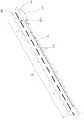
도 2는 본 발명의 바람직한 실시예에 따른 터널용 주광 유입장치의 저면 사시도,
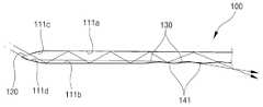
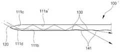
도 3은 본 발명의 바람직한 실시예에 따른 터널용 주광 유입장치의 절개 사시도,
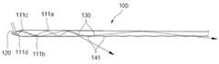
도 4는 본 발명의 바람직한 실시예에 따른 터널용 주광 유입장치가 터널 입구부의 경계부에 설치된 상태를 보여주는 절개 사시도,
도 5a 내지 도 5c는 본 발명의 바람직한 실시예에 따른 터널용 주광 유입장치에 있어서, 광배출구와 반사부의 기울어진 각도에 대한 다양한 변형 실시예를 보여주는 단면도,
도 6a 및 도 6b는 본 발명의 바람직한 실시예에 따른 터널용 주광 유입장치에 있어서, 하지의 정오 때에 광로를 도시한 단면도, 및 이와 대조하여 중공부의 천장면이 바닥면과 평행한 경우의 하지의 정오 때에 광로를 도시한 단면도,
도 7a 및 도 7b는 본 발명의 바람직한 실시예에 따른 터널용 주광 유입장치에 있어서, 동지의 정오 때에 광로를 도시한 단면도, 및 이와 대조하여 중공부의 천장면이 바닥면과 평행한 경우의 동지의 정오 때에 광로를 도시한 단면도이다.1 is a schematic perspective view of a conventional daylight inflow apparatus installed in a building,
2 is a bottom perspective view of a daylight inflow apparatus for a tunnel according to a preferred embodiment of the present invention;
3 is a cutaway perspective view of a daylight inflow apparatus for a tunnel according to a preferred embodiment of the present invention;
4 is a cutaway perspective view showing a state in which a daylight inflow apparatus for a tunnel according to a preferred embodiment of the present invention is installed at a boundary of a tunnel inlet;
5a to 5c are cross-sectional views showing various modified embodiments of the inclination angle of the light outlet and the reflector in the daylight inflow apparatus for the tunnel according to the preferred embodiment of the present invention;
6A and 6B are cross-sectional views showing optical paths at midday of the lower surface of the tunnel in the daylight inflow apparatus according to the preferred embodiment of the present invention, and in contrast, in the case where the ceiling surface of the hollow part is parallel to the floor surface; Section showing the light path at noon,
7A and 7B are cross-sectional views showing an optical path at noon of a winter solstice in a tunnel daylight inflow apparatus according to a preferred embodiment of the present invention, and in contrast with the winter solstice when the ceiling surface of the hollow part is parallel to the floor surface; It is sectional drawing which shows an optical path at noon.
아래에서는 첨부한 도면을 참고로 하여 본 발명의 실시예에 대하여 본 발명이 속하는 기술분야에서 통상의 지식을 가진 자가 용이하게 실시할 수 있도록 상세히 설명한다. 그러나 본 발명은 여러 가지 상이한 형태로 구현될 수 있으며, 그 범위가 여기에서 설명하는 실시예에 한정되지 않는다.DETAILED DESCRIPTION Hereinafter, exemplary embodiments of the present invention will be described in detail with reference to the accompanying drawings so that those skilled in the art may easily implement the present invention. The present invention may, however, be embodied in many different forms and should not be construed as limited to the embodiments set forth herein.
본 발명에 따른 터널용 주광 유입장치는, 터널 입구부터 터널 내측으로 진행하는 순서대로 경계부, 이행부 및 완화부로 이루어지는 터널 입구부, 그 중에서 특히 경계부에 설치되어 주광을 채광하여 경계부의 내부도로에 조사하기 위한 장치이다.In the tunnel daylight inflow apparatus according to the present invention, the tunnel entrance portion consisting of the boundary portion, the transition portion and the relaxation portion in order from the entrance of the tunnel to the inside of the tunnel, among them, especially the boundary portion is provided to mine daylight and irradiate the internal roads of the boundary portion. It is a device for.
이하, 첨부된 도 2 내지 도 7b를 참조하여, 본 발명의 바람직한 실시예에 따른 터널용 주광 유입장치(100)의 구성 및 작용효과를 구체적으로 설명한다.Hereinafter, with reference to the accompanying Figures 2 to 7b, the configuration and operation effects of the
본 발명의 바람직한 실시예에 따른 터널용 주광 유입장치(100)는, 몸체(110), 광유입구(120), 광배출구(130) 및 반사부(140)를 포함하여 이루어진다.Tunnel
상기 몸체(110)는 터널 입구부의 경계부(TE) 천장에 터널의 길이방향을 따라 설치되고, 내부에 중공부(111)가 형성된 긴 덕트 형상으로 이루어져 주광을 전달하는 역할을 하며, 터널용 주광 유입장치(100)의 주 골격을 이룬다.The
상기 몸체(110)의 내부에서는 광유입구(120)로 유입된 주광이 반사되면서 전달되어야 하므로, 몸체(110)의 내면은 반사율이 높은 소재로 이루어진다.The inner surface of the
여기서, 도 3 및 도 4에 도시된 바와 같이, 상기 중공부(111)의 바닥면(111b)은 터널의 내부도로(IR)와 평행하게 구비되고, 중공부(111)의 천장면(111a)은 이 바닥면(111b)에 대하여 터널 입구(TE') 측보다 내측이 낮아지도록 약 0.5°가량 기울어지게 구비된다.
즉, 상기 중공부(111)의 천장면(111a)은, 바닥면(111b)에 대해 광유입구(120)로부터 몸체(110)의 길이방향을 따라 광유입구(120)의 반대편으로 갈수록 그 높이가 낮아지도록 기울어지게 구비된다.3 and 4, the
That is, the height of the
이로 인해 광유입구(120)를 통해 중공부(111)로 유입된 주광은 천장면(111a)이 바닥면(111b)과 평행할 때보다 중공부(111) 내에서의 반사 현상이 추가적으로 더 유발되어 중공부(111)를 따라 터널 내측 방향으로 효과적으로 전달된다. 이에 대해서는 후술되는 본 발명의 동작 및 사용 상태 설명에서 보다 상세히 설명하기로 한다.As a result, the main light flowing into the
본 발명의 바람직한 실시예에 있어서, 상기 몸체(110)는 직육면체 형상과 유사하게 구비되었으나, 주광을 전달할 수 있는 덕트의 형태로 구비되면 족하고, 그 형상이 이에 한정되는 것은 아님을 밝혀둔다.In a preferred embodiment of the present invention, the
상기 광유입구(120)는 몸체(110)의 터널 입구(TE') 측 단부에 상측 방향으로 형성되어 주광이 중공부(111)로 받아들이는 역할을 한다. 즉, 광유입구(120)가 형성된 몸체(110)의 단부는 주광에 노출되게 터널의 외측에 위치된다.The
도 3에 도시된 바와 같이, 이 광유입구(120)가 형성되는 몸체(110)의 단부에 있어서, 중공부(111)의 바닥부(111d)는 터널의 내부도로(IR)와 평행하게 구비되는 중공부(111)의 바닥면(111b)에 대해 약 166°의 각도로 절곡되게 형성되고, 중공부(111)의 천장부(111c)는 천장면(111a)에 대해 약 169°의 각도로 절곡되게 형성된다.As shown in FIG. 3, at the end of the
이러한 중공부(111)의 천장부(111c)와 바닥부(111d)의 내면은 반사율이 높은 소재로 이루어져, 광유입구(120)로 유입되는 주광을 중공부(111) 내측으로 반사한다. 태양의 고도가 낮은 경우에는 광유입구(120)를 통과해 들어온 주광은 중공부(111)의 바닥부(111d)에 반사되어 중공부(111) 내측으로 유입되고, 태양의 고도가 높은 경우에는 광유입구(120)를 통과해 들어온 주광은 중공부(111)의 바닥부(111d)와 천장부(111c)에 순서대로 반사되어 중공부(111) 내측으로 유입된다.The inner surface of the
즉, 상기 중공부(111)의 천장부(111c)는 태양의 고도가 높은 경우 바닥부(111d)에 반사된 주광이 상측으로 반사되어 버리는 것을 차단함으로써, 광유입구(120)를 통과한 대부분의 주광이 중공부(111)로 유입되게 한다.That is, the
본 발명의 바람직한 실시예에 있어서, 상기 중공부(111)의 천장부(111c)와 바닥부(111d)가 각각 중공부(111)의 천장면(111a)과 바닥면(111b)에 대해 이루는 각도는 대한민국 서울에 있어서 하지와 동지의 최대 태양고도를 기준으로 166° 및 169°로 구비되었으나, 이는 본 발명의 터널용 주광 유입장치(100)가 설치되는 지역의 최대 태양고도에 따라 변경될 수 있으며, 몸체(110)와 광유입구(120)의 형상에 따라서도 변경될 수 있는 것으로서, 이에 한정되는 것은 아니다.In a preferred embodiment of the present invention, the angle formed by the
상기 광배출구(130)는 도 3 및 도 4에 도시된 바와 같이, 경계부(TE)에 있어서 터널 입구(TE')에 가장 가까이 위치하여 주광이 직접 조사되는 전두부를 제외한 몸체(110)의 하면에 직사각 형상으로 형성되는데, 소정의 간격을 두고 몸체(110)의 길이방향을 따라 복수가 형성되어 광유입구(120)를 통해 중공부(111)로 유입된 주광이 통과 배출되는 곳이다.As shown in FIGS. 3 and 4, the
이 복수의 광배출구(130)에는 통과하는 주광을 고르게 확산시킬 수 있는 확산부재(131)가 각각 설치될 수 있다.Each of the plurality of
상기 반사부(140)는 복수의 광배출구(130)의 사이에 각각 위치하는 몸체(110)의 일부분으로서 중공부(111) 내부의 주광을 반사하는 역할을 한다. 즉, 광유입구(120)를 통해 중공부(111)로 유입된 주광은 중공부(111) 내에서 반사를 거듭하여 터널의 내측 방향으로 진행하면서, 일부는 광배출구(130)를 통해 배출되고 나머지 일부는 반사부(140)에서 반사되면서 터널의 내측 방향으로 더 진행하게 된다.The
상기 복수의 반사부(140)의 중공부(111) 내측의 상면에는 주광을 반사하는 매우 높은 반사율을 갖는 복수의 반사부재(141)가 각각 구비될 수 있다. 이 복수의 반사부재(141)는 중공부(111) 내에서 주광을 터널 내측 방향으로 전달함에 있어 손실을 줄임으로써 그 전달 효율을 높이는 역할을 한다.A plurality of reflecting
본 발명의 바람직한 실시예에 있어서, 상기 반사부(140)는 복수의 광배출구(130)가 형성된 후, 그 사이에 위치하는 몸체(110)의 일부분으로 형성되게 구현되었으나, 이에 한정되지 않고 광배출구(130)를 이룰 긴 장공을 몸체(110) 하면에 형성한 후 별도로 구비되는 복수의 반사부(140)가 장공에 소정의 간격으로 설치됨으로써 복수의 광배출구(130)가 형성되는 방식으로 구현될 수도 있다.In a preferred embodiment of the present invention, the
한편, 상술한 바와 같이, 광배출구(130)와 반사부(140)는 몸체(110)의 길이방향을 따라 그 하면에 각각 교대로 구비되는 형태를 갖는데, 여기서 도 2 내지 도 4에 도시된 바와 같이, 복수의 광배출구(130)는 터널 내부도로(IR)와 평행하게 구비되는 중공부(111)의 바닥면(111b)에 대해 광유입구(120) 측이 낮아지도록 각각 기울어지게 형성되고, 복수의 반사부(140)는 광유입구(120)의 반대측이 낮아지도록 각각 기울어지게 형성된다.On the other hand, as described above, the
상기 광배출구(130)와 반사부(140)가 이렇게 기울어지게 형성되면, 중공부(111)의 천장면(111a)에 반사된 후 반사부(140)의 반사부재(141)에 입사한 주광이 중공부(111) 내에서 터널 내측 방향으로 더 깊게 입사될 수 있는 방향으로 반사된다. 이에 따라, 주광이 중공부(111)를 통해 경계부(TE) 내측으로 효과적으로 전달되면서 경계부(TE) 내측의 광배출구(130)를 통해 배출되는 광량이 향상된다.When the
이와 상대적으로 광배출구(TE)의 터널 입구(TE') 측에서 광배출구(130)를 통해 배출되는 광량은 감소하면서 광배출구(TE)의 터널 입구(TE') 측의 광량은 과다하고 터널 내측의 광량은 부족한 불균형의 문제가 어느 정도 완화될 수 있다.On the other hand, the amount of light emitted through the
여기서, 광배출구(130)가 중공부(111)의 바닥면(111b)에 대해 기울어진 각도(α) 및 반사부(140)가 중공부(111)의 바닥면(111b)에 대해 기울어진 각도(β)는 3°~ 7°가 바람직하다.Here, the angle α in which the
그 이유는 광배출구(130)와 반사부(140)가 중공부(111)의 바닥면(111b)에 대해 기울어진 각도(α, β)가 3°보다 작을 경우 그 효과가 미미하고, 광배출구(130)가 중공부(111)의 바닥면(111b)에 대해 기울어진 각도(α)가 7°보다 클 경우 광배출구(130)를 통한 주광 배출이 과소해지며, 반사부(140)가 중공부(111)의 바닥면(111b)에 대해 기울어진 각도(β)가 7°보다 클 경우 중공부(111)의 천장면(111a)에서 반사된 주광이 반사부(140)에 입사할 수 있는 각의 범위가 크게 제한되어 반사부(140)에 의한 주광의 반사 전달이 저해됨으로써 오히려 중공부(111) 내에서 터널 내측 방향으로 전달되는 광량이 줄어들 수 있기 때문이다.The reason is that when the angles α and β of the
본 발명의 바람직한 실시예에 있어서, 상기 광배출구(130)와 반사부(140)는 몸체(110)의 길이방향 폭과 그 기울어진 각도가 동일하게 구현되었으나, 이에 한정되는 것은 아니다. 도 5a 내지 도 5c는 광배출구(130)와 반사부(140)는 몸체(110)의 길이방향 폭과 그 기울어진 각도에 대한 다양한 변형 실시예를 도시한 단면도이다.In a preferred embodiment of the present invention, the
즉, 도 5a에 도시된 바와 같이 광배출구(130)가 반사부(140)보다 몸체(110)의 길이방향 폭은 더 작고, 광배출구(130)가 중공부(111)의 바닥면(111b)에 대해 기울어진 각도(α)가 반사부(140)가 중공부(111)의 바닥면(111b)에 대해 기울어진 각도(β)보다 더 크게 구현될 수 있다.That is, as shown in FIG. 5A, the
그리고 도 5b와 같이 광배출구(130)가 중공부(111)의 바닥면(111b)에 대해 기울어진 각도(α1, α2, α3)는 터널 입구(TE') 측에서 내측으로 진행할수록 소정의 구간별로 단계적으로 작아지고(즉, α1 > α2 > α3), 반사부(140)가 중공부(111)의 바닥면(111b)에 대해 기울어진 각도(β)는 터널 입구(TE') 측에서 내측으로 진행할수록 상기 구간별로 단계적으로 커지게(즉, β1 < β2 < β3) 구현될 수도 있다.In addition, as shown in FIG. 5B, the angles α1, α2, and α3 inclined by the
뿐만 아니라, 도 5c와 같이 광배출구(130)가 중공부(111)의 바닥면(111b)에 대해 기울어진 각도(α1, α2, α3) 및 반사부(140)가 중공부(111)의 바닥면(111b)에 대해 기울어진 각도(β1, β2, β3)는 터널 입구(TE') 측에서 내측으로 진행할수록 그 진행거리에 선형으로 비례하여 점진적으로 작아지거나 커지도록 구현될 수도 있다.In addition, as illustrated in FIG. 5C, the angles α1, α2, and α3 inclined with respect to the
여기서 가장 바람직한 것은 도 5c에 도시된 경우라 할 수 있는데, 그 이유는 광배출구(130)와 반사부(140)의 길이방향 폭과 기울어진 각도가 이처럼 구비될 경우, 반사부(140)의 기울어짐에 따라 터널 내측으로 전달되는 광량은 증가되고 광배출구(130)의 길이방향 폭이 터널 내측으로 갈수록 증가하여, 동일한 조건일 때 상대적으로 많은 광량이 터널 내측의 광배출구(130)로 통과 배출될 수 있기 때문이다.The most preferred here may be the case shown in Figure 5c, the reason is that when the longitudinal width and the inclined angle of the
다시 말해, 중공부(111) 내에서 터널 내측 방향으로 갈수록 중공부(111) 내에 존재하는 광량은 감소하게 되므로, 이에 따라 경계부(TE)의 터널 내측에 조사되는 광량을 증가시키기 위해서는 동일한 조건에서 더 많은 광량이 배출될 수 있도록 광배출구(130)를 구현하는 것이 효과적이기 때문이다.In other words, the amount of light present in the
상술한 바와 같은 터널용 주광 유입장치가 터널 입구부의 경계부(TE), 특히 터널 입구(TE') 측보다는 내측에 위치한 내부도로에 요구되는 광량을 충족시키기에 부족한 경우에는 그 부족한 만큼만 별도의 조명장치를 터널 내측에 설치 및 작동시키면 충분하므로, 저렴한 비용으로 터널 입구부의 경계부(TE) 전체에 대한 조명을 해결할 수 있다.
If the above-mentioned primary daylight inflow device for the tunnel is insufficient to satisfy the amount of light required for the interior road located at the inner side of the tunnel inlet of the tunnel, particularly the tunnel entrance TE ', the only separate lighting device is sufficient. It is sufficient to install and operate inside the tunnel, so that it is possible to solve the illumination of the entire boundary TE of the tunnel entrance at low cost.
이하, 도 4 및 도 6a 내지 도 7b를 참조하여, 본 발명의 바람직한 실시예에 따른 터널용 주광 유입장치(100)의 동작 및 사용 상태를 구체적으로 설명한다.4 and 6a to 7b, the operation and use state of the
본 발명에 따른 터널용 주광 유입장치(100)는 도 4에 도시된 바와 같이, 터널 입구부의 경계부(TE) 천장 중심에 터널의 길이방향을 따라 설치되고, 이때 광유입구(120)가 형성된 단부는 터널의 외측으로 돌출되어 주광이 광유입구(120)로 유입될 수 있도록 설치한다.As shown in FIG. 4, the tunnel
이렇게 설치된 터널용 주광 유입장치(100)의 광유입구(120)에 자연적으로 조사되는 주광의 조사 각도는 시간 및 절기에 따라 연속적으로 변하게 되는데, 도 6a 및 도 7a는 각각 하지와 동지의 정오 때에 조사되는 주광의 조사 각도를 기준으로 주광이 진행하는 광로를 표시한 단면도이다.The irradiation angle of the daylight naturally irradiated to the
도 6a와 같이 주광의 조사 각도가 큰 경우에는 광유입구(120)로 입사된 주광은 중공부(111)의 바닥부(111d) 및 천장부(111c)에 순차적으로 반사되고, 이후 중공부(111)의 바닥면(111b)과 천장면(111a)에 반복적으로 반사된다.6A, when the irradiation angle of the chief light is large, the chief light incident on the
그 후, 광배출구(130)에 이르러서는 유입된 주광의 일부는 광배출구(130)의 확산부재(131)를 통과해 하측으로 배출되고, 나머지 일부는 반사부(140)의 반사부재(141)에 의해 반사됨으로써 중공부의 바닥면(111b)에 의해 반사된 것보다 완만한 기울기로 중공부(111)의 내측 깊이 전달된다.Thereafter, a part of the main light introduced into the
여기서 중공부(111)의 바닥면(111b)이 존재하는 영역은 경계부(TE)에서도 가장 터널 입구(TE') 측에 해당하는 구간으로서, 터널 입구(TE')를 통해 주광이 직접 유입되므로 광조사가 필요 없는 구간이다.Here, the area where the
앞서 설명한 바와 같이, 반사부(140) 및 반사부재(141)에 의해 중공부(111)로 유입된 주광은 짧은 광로와 적은 손실로 중공부(111)의 내측에 전달될 수 있다. 이러한 주광은 복수의 반사부(140)에 구비된 반사부재(141)와 중공부(111)의 천장면(111a)에서 반복적으로 반사되면서 복수의 광배출구(130)를 통해 완화부(TE-3)에 조사된다.As described above, the main light introduced into the
이에 따라, 상대적으로 경계부(TE)의 터널 입구(TE') 측에 위치한 광배출구(130)를 통해 배출되는 광량은 광배출구(130)와 반사부(140)가 수평인 경우보다 적어지고 경계부(TE)의 터널 내측에 위치한 광배출구(130)를 통해 배출되는 광량은 증가하여, 부족한 터널 내측 경계부(TE)의 내부도로(IR)에 조사되는 광량이 증가될 수 있다.Accordingly, the amount of light emitted through the
한편, 중공부(111)로 유입된 주광이 천장면(111a)에서 반사될 때, 이 천장면(111a)이 약 0.5°정도 기울어지게 구비됨으로써, 중공부(111) 내부에서의 주광의 추가적인 반사를 유발하여 이 주광을 더 멀리 중공부(111) 내측으로 전달한다.On the other hand, when the chief light flowing into the
도 6b는 도 6a에 도시한 본 발명의 바람직한 실시예의 경우와 비교하기 위해 중공부(111)의 천장면(111a')을 바닥면(111b)과 같이 수평으로 구비된 경우를 도시한 것인데, 도 6a와 도 6b에 점선으로 표시한 광로를 비교해 볼 때, 도 6a의 광로를 그리는 주광은 기울어진 천장면(111a)에 의해 더 많이 꺾이면서 첫 번째 반사부(140)에 의한 추가적인 반사가 유발되어 해당 주광이 중공부(111) 내측으로 더 전달되는 것을 알 수 있다.FIG. 6B illustrates a case where the
한편, 도 7a와 같이 주광의 조사 각도가 작은 경우에는 광유입구(120)로 입사된 주광은 중공부(111)의 바닥부(111d)에 반사된 후, 바로 중공부(111)의 천장면(111a)에서 반사되며, 이후 중공부(111)의 바닥면(111b)과 천장면(111a)에 반복적으로 반사된다.On the other hand, as shown in FIG. 7A, when the irradiation angle of the chief light is small, the chief light incident on the
그 후, 주광의 일부가 경계부(TE)의 터널 입구(TE') 측에 위치한 광배출구(130)의 확산부재(131)를 통과해 하측으로 배출되고, 나머지 일부는 반사부(140)의 반사부재(141)에 의해 반사되어 중공부(111)의 내측으로 더 깊이 진행한 후 터널 내측에 위치한 광배출구(130)를 통해 배출되는 것은 앞선 도 6a에 대한 설명과 유사하다.Thereafter, a part of the chief light is discharged downward through the
또한, 이때 기울어지게 구비된 광배출구(130)와 반사부(140)에 의해, 상대적으로 경계부(TE)의 터널 입구(TE') 측에 위치한 광배출구(130)를 통해 배출되는 광량은 광배출구(130)와 반사부(140)가 수평인 경우보다 적어지고 터널 내측에 위치한 광배출구(130)를 통해 배출되는 광량은 증가하여, 부족한 터널 내측의 내부도로(IR)에 조사되는 광량이 증가하는 것도 도 6a에 대한 설명과 대동소이하다.In addition, at this time, the amount of light emitted through the
도 7b는 도 7a에 도시한 본 발명의 바람직한 실시예의 경우와 비교하기 위해 중공부(111)의 천장면(111a')을 바닥면(111b)과 같이 수평으로 구비된 경우를 도시한 것인데, 도 7a와 도 7b에 점선으로 표시한 광로를 비교해 볼 때, 도 7a의 광로를 그리는 주광은 기울어진 천장면(111a)에 의해 더 많이 꺾이면서 첫 번째 반사부(140)에 의한 추가적인 반사가 유발되어 해당 주광이 중공부(111) 내측으로 더 전달되는 것을 역시 확인할 수 있다.FIG. 7B illustrates a case where the
상술한 바와 같이, 본 발명에 따른 터널용 주광 유입장치(100)에 의하면, 몸체(110)의 하면에 길이방향을 따라 광배출구(130)와 반사부(140)를 번갈아 배치하고, 이 광배출구(130) 및 반사부(140)는 각각 광유입구(120) 측 및 광유입구(120)의 반대측이 낮아지도록 기울어지게 구비됨으로써, 터널 입구부의 경계부(TE)에 있어서 터널 입구(TE') 측뿐만 아니라 터널 내측의 내부도로(IR)에도 주광이 효과적으로 조사되므로 경계부(TE) 전체에 바람직하게 적용될 수 있다.As described above, according to the tunnel
이상에서 본 발명은 기재된 구체예에 대해서만 상세히 설명되었지만, 본 발명의 기술사상 범위 내에서 다양한 변형 및 수정이 가능함은 당업자에게 있어 명백한 것이며, 이러한 변형 및 수정이 첨부되어 있는 특허청구범위에 속함은 당연한 것이다.Although the present invention has been described in detail only with respect to the described embodiments, it will be apparent to those skilled in the art that various modifications and variations are possible within the technical spirit of the present invention, and such modifications and variations belong to the appended claims. will be.
* 도면의 주요 부분에 대한 부호의 설명 *
100, 100' : 터널용 주광 유입장치 110 : 몸체
111 : 중공부 111a, 111a' : 중공부의 천장면
111b : 중공부의 바닥면 111c : 중공부의 천장부
111d : 중공부의 바닥부 120 : 광유입구
130 : 광배출구 131 : 확산부재
140 : 반사부 141 : 반사부재
TE : 터널 입구부의 경계부 TE' : 터널 입구
IR : 내부도로
α, α1, α2, α3 : 광배출구가 중공부의 바닥면에 대해 기울어진 각도
β, β1, β2, β3 : 반사부가 중공부의 바닥면에 대해 기울어진 각도Description of the Related Art [0002]
100, 100 ': Daylight inflow device for tunnel 110: Body
111:
111b: Bottom surface of
111d: bottom portion of hollow portion 120: light inlet
130: light outlet 131: diffusion member
140: reflection unit 141: reflection member
TE: boundary of the tunnel entrance TE ': tunnel entrance
IR: inside road
α, α1, α2, α3: angle at which the light exit port is inclined with respect to the bottom surface of the hollow part
β, β1, β2, β3: angle at which the reflecting portion is inclined with respect to the bottom surface of the hollow portion
Claims (9)
Translated fromKorean상기 중공부로 주광이 유입되도록 상기 몸체의 상기 터널 입구 측 단부에 형성되는 광유입구;
상기 중공부로 유입된 상기 주광이 상기 몸체 하측에 위치한 상기 터널의 내부도로에 조사될 수 있도록 상기 몸체의 하면에 형성되는 복수의 광배출구; 및
상기 복수의 광배출구의 사이에 각각 위치하고 상기 중공부 내부의 상기 주광을 반사하는 복수의 반사부;를 포함하되,
상기 복수의 광배출구는 상기 중공부의 바닥면에 대해 상기 광유입구 측이 낮아지도록 각각 기울어지는 각도(α)를 가지도록 형성되고, 상기 복수의 반사부는 상기 광유입구의 반대측이 낮아지도록 각각 기울어지는 각도(β)를 가지도록 형성되는 것을 특징으로 하는 터널용 주광 유입장치.A body having a long duct shape to be installed along the longitudinal direction of the tunnel at the boundary ceiling of the tunnel inlet, and having a hollow portion formed therein;
A light inlet formed at an end of the tunnel inlet side of the body so that daylight flows into the hollow part;
A plurality of light outlets formed on a lower surface of the body so that the chief light flowing into the hollow portion is irradiated onto an inner road of the tunnel located below the body; And
It includes; a plurality of reflecting portions respectively disposed between the plurality of light outlets for reflecting the main light inside the hollow portion,
The plurality of light outlets are formed to have an angle α inclined so that the light inlet side is lower with respect to the bottom surface of the hollow part, and the plurality of reflecting parts are respectively inclined so that the opposite side of the light inlet is lowered. Daylight inflow device for a tunnel, characterized in that it is formed to have (β).
상기 복수의 광배출구가 상기 중공부의 바닥면에 대해 기울어진 각도(α)는 각각 3°~ 7°인 것을 특징으로 하는 터널용 주광 유입장치.The method of claim 1,
Angle of inclination of the plurality of light outlets with respect to the bottom surface of the hollow portion (α) is a daylight inlet device for a tunnel, characterized in that each of 3 ° ~ 7 °.
상기 복수의 반사부가 상기 중공부의 바닥면에 대해 기울어진 각도(β)는 각각 3°~ 7°인 것을 특징으로 하는 터널용 주광 유입장치.The method of claim 1,
Angle of inclination of the plurality of reflecting portion with respect to the bottom surface of the hollow portion (β) is a daylight inlet device for a tunnel, characterized in that each 3 ° ~ 7 °.
상기 복수의 광배출구가 상기 중공부의 바닥면에 대해 기울어진 각도(α)는 광유입구의 반대측으로 갈수록 감소하도록 형성되는 것을 특징으로 하는 터널용 주광 유입장치.The method of claim 2,
Angle of inclination of the plurality of light outlets with respect to the bottom surface of the hollow portion α is formed so as to decrease toward the opposite side of the light inlet.
상기 복수의 반사부가 상기 중공부의 바닥면에 대해 기울어진 각도(β)는 광유입구의 반대측으로 갈수록 증가하도록 형성되는 것을 특징으로 하는 터널용 주광 유입장치.The method of claim 3,
And a plurality of reflecting portions inclined with respect to the bottom surface of the hollow part are formed to increase toward the opposite side of the light inlet.
상기 복수의 광배출구가 상기 중공부의 바닥면에 대해 기울어진 각도(α)는 광유입구의 반대측으로 갈수록 선형적으로 또는 구간별로 단계적으로 감소하도록 형성되는 것을 특징으로 하는 터널용 주광 유입장치.The method of claim 4, wherein
The angle of inclination of the plurality of light outlets with respect to the bottom surface of the hollow portion (α) is formed so as to decrease linearly or step by step toward the opposite side of the light inlet tunnel, daylight inflow apparatus for a tunnel.
상기 복수의 반사부가 상기 중공부의 바닥면에 대해 기울어진 각도(β)는 광유입구의 반대측으로 갈수록 선형적으로 또는 구간별로 단계적으로 증가하도록 형성되는 것을 특징으로 하는 터널용 주광 유입장치.The method of claim 5,
Angle of inclination of the plurality of reflecting portion with respect to the bottom surface of the hollow portion is inclined toward the opposite side of the light inlet is formed to increase linearly or step by step step by step.
상기 복수의 반사부는,
상기 중공부 내측의 그 상면에 상기 주광을 반사하도록 설치된 반사부재;
를 포함하는 것을 특징으로 하는 터널용 주광 유입장치.The method according to any one of claims 1 to 7,
The plurality of reflectors,
A reflecting member provided on the upper surface of the hollow part to reflect the main light;
Tunnel daylight inlet device comprising a.
상기 중공부의 천장면은,
상기 내부도로와 평행하게 구비되는 상기 중공부의 바닥면에 대하여 상기 광유입구로부터 상기 몸체의 길이방향을 따라 상기 광유입구의 반대편으로 갈수록 그 높이가 낮아지도록 기울어지게 구비된 것을 특징으로 하는 터널용 주광 유입장치.The method according to any one of claims 1 to 7,
The ceiling surface of the hollow portion,
The daylight inflow for the tunnel, characterized in that the inclined so as to lower the height toward the opposite side of the light inlet from the light inlet in the longitudinal direction of the body with respect to the bottom surface of the hollow portion provided in parallel with the inner road Device.
Priority Applications (1)
| Application Number | Priority Date | Filing Date | Title |
|---|---|---|---|
| KR1020100004867AKR101129227B1 (en) | 2010-01-19 | 2010-01-19 | Daylight guide apparatus for tunnel |
Applications Claiming Priority (1)
| Application Number | Priority Date | Filing Date | Title |
|---|---|---|---|
| KR1020100004867AKR101129227B1 (en) | 2010-01-19 | 2010-01-19 | Daylight guide apparatus for tunnel |
Publications (2)
| Publication Number | Publication Date |
|---|---|
| KR20110085209A KR20110085209A (en) | 2011-07-27 |
| KR101129227B1true KR101129227B1 (en) | 2012-03-26 |
Family
ID=44922038
Family Applications (1)
| Application Number | Title | Priority Date | Filing Date |
|---|---|---|---|
| KR1020100004867AExpired - Fee RelatedKR101129227B1 (en) | 2010-01-19 | 2010-01-19 | Daylight guide apparatus for tunnel |
Country Status (1)
| Country | Link |
|---|---|
| KR (1) | KR101129227B1 (en) |
Citations (4)
| Publication number | Priority date | Publication date | Assignee | Title |
|---|---|---|---|---|
| US20070274095A1 (en)* | 2006-05-24 | 2007-11-29 | Destain Patrick R | Backlight wedge with adjacent reflective surfaces |
| US20070279931A1 (en)* | 2006-05-24 | 2007-12-06 | Bryan William J | Backlight asymmetric light input wedge |
| WO2008038016A1 (en)* | 2006-09-29 | 2008-04-03 | Cambridge Flat Projection Displays Ltd | Flat-panel optical projection apparatus |
| WO2008040960A1 (en)* | 2006-10-02 | 2008-04-10 | Cambridge Flat Projection Displays Ltd | Flat-panel optical projection apparatus with reduced distortion |
- 2010
- 2010-01-19KRKR1020100004867Apatent/KR101129227B1/ennot_activeExpired - Fee Related
Patent Citations (4)
| Publication number | Priority date | Publication date | Assignee | Title |
|---|---|---|---|---|
| US20070274095A1 (en)* | 2006-05-24 | 2007-11-29 | Destain Patrick R | Backlight wedge with adjacent reflective surfaces |
| US20070279931A1 (en)* | 2006-05-24 | 2007-12-06 | Bryan William J | Backlight asymmetric light input wedge |
| WO2008038016A1 (en)* | 2006-09-29 | 2008-04-03 | Cambridge Flat Projection Displays Ltd | Flat-panel optical projection apparatus |
| WO2008040960A1 (en)* | 2006-10-02 | 2008-04-10 | Cambridge Flat Projection Displays Ltd | Flat-panel optical projection apparatus with reduced distortion |
Also Published As
| Publication number | Publication date |
|---|---|
| KR20110085209A (en) | 2011-07-27 |
Similar Documents
| Publication | Publication Date | Title |
|---|---|---|
| CN102202937A (en) | Light guide element for a lighting device | |
| JP4030431B2 (en) | lighting equipment | |
| CN105874271A (en) | Acoustic lighting tile | |
| KR20160038467A (en) | Apparatus for ventilating and lighting in underground structure, and method for constructing the same | |
| KR20130066371A (en) | Apparatus for lightening tunnel | |
| KR101129227B1 (en) | Daylight guide apparatus for tunnel | |
| KR101684931B1 (en) | Indirect lighting system for tunnel entrance zone | |
| KR102229099B1 (en) | Lighting device | |
| KR101123275B1 (en) | Led high intensity single-side floodlights having a light diffusing lens | |
| JP4793270B2 (en) | Aisle lighting | |
| WO2023103214A1 (en) | Urban street lamp system capable of eliminating alternating shadow lines | |
| KR101831288B1 (en) | Blind for led media facade | |
| KR100962041B1 (en) | Device for light street lighting car lane and sidewalk | |
| KR20090048890A (en) | Tunnel wall mounting tiles and tunnel lighting system comprising the same | |
| KR101502774B1 (en) | Auxiliary Road Tunnel | |
| Iqbal et al. | Energy saving potential in buildings for Karachi climate using daylight | |
| CN208170288U (en) | Electric bicycle and its lamp bar component | |
| KR101276624B1 (en) | Division daylighting apparatus | |
| KR20210050737A (en) | Mist lighting device | |
| JP4203500B2 (en) | Light irradiation device | |
| KR200411153Y1 (en) | Warning light | |
| ITMI20062063A1 (en) | RECESSED LUMINAIRE FOR UNIFORM LIGHTING OF WALLS | |
| CN101535712A (en) | Device for mixing light of side emitting LEDs | |
| CN205918006U (en) | Roof daylighting device | |
| CN217423055U (en) | Blackboard lamp |
Legal Events
| Date | Code | Title | Description |
|---|---|---|---|
| A201 | Request for examination | ||
| PA0109 | Patent application | St.27 status event code:A-0-1-A10-A12-nap-PA0109 | |
| PA0201 | Request for examination | St.27 status event code:A-1-2-D10-D11-exm-PA0201 | |
| D13-X000 | Search requested | St.27 status event code:A-1-2-D10-D13-srh-X000 | |
| D14-X000 | Search report completed | St.27 status event code:A-1-2-D10-D14-srh-X000 | |
| E902 | Notification of reason for refusal | ||
| PE0902 | Notice of grounds for rejection | St.27 status event code:A-1-2-D10-D21-exm-PE0902 | |
| P11-X000 | Amendment of application requested | St.27 status event code:A-2-2-P10-P11-nap-X000 | |
| P13-X000 | Application amended | St.27 status event code:A-2-2-P10-P13-nap-X000 | |
| PG1501 | Laying open of application | St.27 status event code:A-1-1-Q10-Q12-nap-PG1501 | |
| E701 | Decision to grant or registration of patent right | ||
| PE0701 | Decision of registration | St.27 status event code:A-1-2-D10-D22-exm-PE0701 | |
| R18-X000 | Changes to party contact information recorded | St.27 status event code:A-3-3-R10-R18-oth-X000 | |
| N231 | Notification of change of applicant | ||
| PN2301 | Change of applicant | St.27 status event code:A-3-3-R10-R11-asn-PN2301 St.27 status event code:A-3-3-R10-R13-asn-PN2301 | |
| GRNT | Written decision to grant | ||
| PR0701 | Registration of establishment | St.27 status event code:A-2-4-F10-F11-exm-PR0701 | |
| PR1002 | Payment of registration fee | Fee payment year number:1 St.27 status event code:A-2-2-U10-U11-oth-PR1002 | |
| PG1601 | Publication of registration | St.27 status event code:A-4-4-Q10-Q13-nap-PG1601 | |
| PN2301 | Change of applicant | St.27 status event code:A-5-5-R10-R11-asn-PN2301 St.27 status event code:A-5-5-R10-R13-asn-PN2301 | |
| R18-X000 | Changes to party contact information recorded | St.27 status event code:A-5-5-R10-R18-oth-X000 | |
| FPAY | Annual fee payment | Payment date:20150313 Year of fee payment:4 | |
| PR1001 | Payment of annual fee | Fee payment year number:4 St.27 status event code:A-4-4-U10-U11-oth-PR1001 | |
| PN2301 | Change of applicant | St.27 status event code:A-5-5-R10-R11-asn-PN2301 St.27 status event code:A-5-5-R10-R13-asn-PN2301 | |
| PR1001 | Payment of annual fee | Fee payment year number:5 St.27 status event code:A-4-4-U10-U11-oth-PR1001 | |
| P22-X000 | Classification modified | St.27 status event code:A-4-4-P10-P22-nap-X000 | |
| PR1001 | Payment of annual fee | Fee payment year number:6 St.27 status event code:A-4-4-U10-U11-oth-PR1001 | |
| FPAY | Annual fee payment | Payment date:20180307 Year of fee payment:7 | |
| PR1001 | Payment of annual fee | Fee payment year number:7 St.27 status event code:A-4-4-U10-U11-oth-PR1001 | |
| P22-X000 | Classification modified | St.27 status event code:A-4-4-P10-P22-nap-X000 | |
| PN2301 | Change of applicant | St.27 status event code:A-5-5-R10-R11-asn-PN2301 St.27 status event code:A-5-5-R10-R13-asn-PN2301 | |
| R18-X000 | Changes to party contact information recorded | St.27 status event code:A-5-5-R10-R18-oth-X000 | |
| LAPS | Lapse due to unpaid annual fee | ||
| PC1903 | Unpaid annual fee | Not in force date:20190316 Payment event data comment text:Termination Category : DEFAULT_OF_REGISTRATION_FEE St.27 status event code:A-4-4-U10-U13-oth-PC1903 | |
| PC1903 | Unpaid annual fee | Ip right cessation event data comment text:Termination Category : DEFAULT_OF_REGISTRATION_FEE Not in force date:20190316 St.27 status event code:N-4-6-H10-H13-oth-PC1903 | |
| R18-X000 | Changes to party contact information recorded | St.27 status event code:A-5-5-R10-R18-oth-X000 | |
| R18-X000 | Changes to party contact information recorded | St.27 status event code:A-5-5-R10-R18-oth-X000 |