KR101129016B1 - Fuel injecting device and method for controlling said device - Google Patents
Fuel injecting device and method for controlling said deviceDownload PDFInfo
- Publication number
- KR101129016B1 KR101129016B1KR1020087004631AKR20087004631AKR101129016B1KR 101129016 B1KR101129016 B1KR 101129016B1KR 1020087004631 AKR1020087004631 AKR 1020087004631AKR 20087004631 AKR20087004631 AKR 20087004631AKR 101129016 B1KR101129016 B1KR 101129016B1
- Authority
- KR
- South Korea
- Prior art keywords
- needle
- rod
- head
- actuator
- weight
- Prior art date
- Legal status (The legal status is an assumption and is not a legal conclusion. Google has not performed a legal analysis and makes no representation as to the accuracy of the status listed.)
- Active
Links
Images
Classifications
- F—MECHANICAL ENGINEERING; LIGHTING; HEATING; WEAPONS; BLASTING
- F02—COMBUSTION ENGINES; HOT-GAS OR COMBUSTION-PRODUCT ENGINE PLANTS
- F02M—SUPPLYING COMBUSTION ENGINES IN GENERAL WITH COMBUSTIBLE MIXTURES OR CONSTITUENTS THEREOF
- F02M69/00—Low-pressure fuel-injection apparatus ; Apparatus with both continuous and intermittent injection; Apparatus injecting different types of fuel
- F02M69/04—Injectors peculiar thereto
- F02M69/041—Injectors peculiar thereto having vibrating means for atomizing the fuel, e.g. with sonic or ultrasonic vibrations
- F—MECHANICAL ENGINEERING; LIGHTING; HEATING; WEAPONS; BLASTING
- F02—COMBUSTION ENGINES; HOT-GAS OR COMBUSTION-PRODUCT ENGINE PLANTS
- F02M—SUPPLYING COMBUSTION ENGINES IN GENERAL WITH COMBUSTIBLE MIXTURES OR CONSTITUENTS THEREOF
- F02M2200/00—Details of fuel-injection apparatus, not otherwise provided for
- F02M2200/21—Fuel-injection apparatus with piezoelectric or magnetostrictive elements
- F—MECHANICAL ENGINEERING; LIGHTING; HEATING; WEAPONS; BLASTING
- F02—COMBUSTION ENGINES; HOT-GAS OR COMBUSTION-PRODUCT ENGINE PLANTS
- F02M—SUPPLYING COMBUSTION ENGINES IN GENERAL WITH COMBUSTIBLE MIXTURES OR CONSTITUENTS THEREOF
- F02M51/00—Fuel-injection apparatus characterised by being operated electrically
- F02M51/06—Injectors peculiar thereto with means directly operating the valve needle
- F02M51/0603—Injectors peculiar thereto with means directly operating the valve needle using piezoelectric or magnetostrictive operating means
Landscapes
- Engineering & Computer Science (AREA)
- Chemical & Material Sciences (AREA)
- Combustion & Propulsion (AREA)
- Mechanical Engineering (AREA)
- General Engineering & Computer Science (AREA)
- Fuel-Injection Apparatus (AREA)
Abstract
Translated fromKoreanDescription
Translated fromKorean본 발명은 연료 분사 장치, 상세하게는 내부 연소 엔진을 위한 연료 분사 장치 및 그 제어 방법에 관한 것이다.The present invention relates to a fuel injection device, in particular a fuel injection device for an internal combustion engine and a control method thereof.
문서 FR 2 854 664는 니들(needle)이 설치된 관 모양(tubular) 본체를 포함하는 분사 장치를 개시한다. 상기 니들은 상기 관 모양 본체의 상기 단부에 의해 제공되는 시트를 구비한 밸브로서 작동하는 헤드에서 끝난다. 압축된 연료는 상기 관 모양 본체 내로 공급되고 상기 밸브에서 멈춘다. 상기 전기활성(electroactive) 재료가 여기되면, 그것은 연장되고, 이는 상기 니들의 탄성 신장(elastic lengthening)에 기인하고 따라서 상기 시트(seat)로부터 상기 헤드(head)를 분리한다. 그리고 나서 상기 밸브는 개방되고 상기 연료는 연소 챔버 내로 분사되도록 상기 시트(seat)와 상기 헤드(head) 사이를 통과한다.
이와 같은 분사기(injector)와 함께, 최대 밸브 올림(lift)을 위한 응답 시간은 매우 짧은데, 일반적으로 50㎲보다 작다. 따라서 상기 분사 기간 동안 항상 상기 밸브가 실질적으로 개방되는 범위를 제어하는 것이 가능하다. 순간적인 (instantaneous) 연료 방출 및 소적(droplet)의 형성은 따라서 제어된다.With such an injector, the response time for the maximum valve lift is very short, typically less than 50 ms. It is thus possible to control the extent to which the valve is substantially open at all times during the injection period. Instantaneous fuel release and droplet formation are thus controlled.
그러나, 상기 전기활성 재료가 상기 헤드에 매우 근접하게 되는 것이 필요하다. 여기서, 상기 연소 챔버에 대한 근접 때문에, 상기 전기활성 재료가 그것의 조작에 유해한 온도까지 올라갈 수 있다. 더불어, 상기 분사기의 상기 팁(tip)에 근접하도록 설치하는 것은 공간 활용성의 문제를 야기할 수 있다.However, it is necessary for the electroactive material to be very close to the head. Here, due to the proximity to the combustion chamber, the electroactive material can rise to temperatures harmful to its operation. In addition, installation close to the tip of the injector can cause problems of space utilization.
따라서 본 발명의 목적은 상기 밸브 헤드의 위치가 정확하게 제어될 수 있고, 양호한 응답 시간을 가지고, 상기 전기활성 재료가 수용가능한 조건 하에서 조작할 수 있는 연료 분사 장치를 제안하는 것이다.It is therefore an object of the present invention to propose a fuel injector which can accurately control the position of the valve head, has a good response time, and can be operated under conditions in which the electroactive material is acceptable.
이러한 목적을 염두에 두고, 본 발명의 주제(subject)는 원통형 본체(11, 12), 상기 원통형 본체의 일 단부에 의해서 제공되는 시트(14)에 밸브로서 작동하는 헤드(head)(20)를 일 단부에 가지는 니들(needle)(2), 로드(30)를 포함하고 상기 헤드(20)가 상기 밸브를 개방하기 위하여 이동할 수 있도록 하는, 전기활성(electroactive) 재료 액츄에이터(actuator)(3), 상기 로드(30)가 연장된 중량체(weight)(34), 상기 니들(2)과 상기 로드(30)의 반대편 단부들에 대해 가압되는 중량체(34)를 유지하는 프리로딩(preloading) 장치(35, 36, 37, 33)를 포함하고, 상기 니들(2)은 바(bar)의 형태로 상기 원통형 본체(11, 12)에 대하여 같은 축 상에서 이어지고, 상기 니들(2)은 주어진 여기 주파수(excitation frequency)에서 축 방향 충격을 액츄에이터(3)에 의해 가할 때 축 방향 공진될 수 있고, 따라서 상기 니들(2)의 상기 전체적인 움직임 상에 상기 헤드(20)의 진동 움직임을 보충할 수 있는 것을 특징으로 하는 연료 분사 장치(fuel injection device)이다.With this object in mind, the subject of the present invention includes a
상기 바(bar)의 길이는 상기 액츄에이터(actuator)가 상기 장치의 상기 본체에서 상기 헤드로부터 이격되어 위치하도록 하고, 따라서 상기 연소 챔버의 상기 열에 덜 노출되도록 한다. 상기 여기 주파수(excitation frequency)는 상기 축 방향에서 상기 니들의 연속적인 압축 및 신장을 통하여 공진(resonance)을 얻도록, 상기 니들의 자연 주파수와 가깝도록 선택된다. 나아가, 상기 바가 상기 장치의 상기 축 방향에서 공진할 수 있도록 세팅되어 있는 사실은 상기 선택된 여기 주파수에서 상기 축 방향에서 헤드 변위 모드를 얻을 수 있도록 한다. 예를 들어, 상기 선택된 주파수는 상기 진동(oscillation) 주기가 상기 분사 단계의 지속 또는 분사 주기보다 훨씬 짧도록 선택된다. 상기 헤드의 진동은 변경된 상기 연료 방출을 허용하고 따라서 매우 미세한 연료 방울 형성 제어를 제공한다. 이러한 진동들(상기 진동 운동의 도달)은 상기 니들의 상기 전체적인 운동 상에 놓인다. 상기 두 동작들은 동시에 발생한다. 상기 로드가 신호의 영향하에서 변형될 때, 그것은 상기 니들에 대한 일 단부와 상기 중량체에 대한 타 단부를 누른다. 상기 로드에 대한 상기 중량체의 반작용은 상기 니들에 전달되도록 상기 바의 움직임의 필수적인 부분을 허용한다.The length of the bar allows the actuator to be positioned away from the head in the body of the apparatus and thus less exposed to the heat of the combustion chamber. The excitation frequency is chosen to be close to the natural frequency of the needle to obtain resonance through successive compression and extension of the needle in the axial direction. Furthermore, the fact that the bar is set to resonate in the axial direction of the device makes it possible to obtain a head displacement mode in the axial direction at the selected excitation frequency. For example, the selected frequency is selected such that the oscillation period is much shorter than the duration of the spraying step or the spraying period. The vibration of the head allows for the modified fuel release and thus provides very fine fuel droplet formation control. These vibrations (the arrival of the vibrational motion) lie on the overall motion of the needle. The two operations occur simultaneously. When the rod is deformed under the influence of the signal, it presses one end on the needle and the other end on the weight. The reaction of the weight against the rod allows an integral part of the movement of the bar to be transmitted to the needle.
일 예로서, 상기 여기 주파수는 10부터 30kHz 까지 연장되는 범위 내에 있다. 따라서 상기 분사 단계 동안 매우 미세한 세적(fine droplet)들의 형성이 가능해진다.As an example, the excitation frequency is in a range extending from 10 to 30 kHz. Thus, very fine droplets can be formed during the spraying step.
제1 실시예에서, 상기 로드는 자기-변형성(magnetostrictive) 재료로 만들어지고, 상기 로드 내에 자기장을 발생시킬 수 있는 코일로 둘러싸여 진다. 이러한 재료가 자기장을 겪을 때, 그것은 상기 니들로 전달되는 신장을 경험한다. 상기 니들은 따라서 상기 밸브를 개방하는 방향으로 축 상에서 이동한다. 상기 자기장의 주파수에 의존하여, 상기 니들은 그 전체가 이동하거나, 낮은 주파수의 경우에, 만약 상기 자기장이 상기 니들이 공진할 수 있도록 하는 여기 주파수라면, 즉 상기 니들의 자연 주파수와 근접한 주파수라면, 공진 상태에서 신장 및 수축될 것이다.In a first embodiment, the rod is made of magnetostrictive material and is surrounded by a coil capable of generating a magnetic field in the rod. When this material experiences a magnetic field, it experiences an extension to the needle. The needle thus moves on the axis in the direction of opening the valve. Depending on the frequency of the magnetic field, the needle resonates in its entirety or, in the case of low frequencies, if the magnetic field is an excitation frequency that allows the needle to resonate, i.e., a frequency close to the natural frequency of the needle. Will stretch and contract in the condition.
바람직하게, 강자성(ferromagnetic) 재료로 만들어진 튜브가 상기 코일을 둘러싼다. 따라서, 상기 로드 내에서 생성된 상기 자기장은 상기 튜브에 의해서 스스로 순환되고, 따라서 상기 코일의 효율이 증가한다.Preferably, a tube made of ferromagnetic material surrounds the coil. Thus, the magnetic field generated in the rod is circulated by the tube itself, thus increasing the efficiency of the coil.
제2 실시예에서, 상기 로드는 압전(壓電)(piezoelectric) 재료로 만들어진다.In a second embodiment, the rod is made of piezoelectric material.
바람직하게, 상기 중량체의 임피던스는 상기 니들의 임피던스보다 크다. 상기 임피던스는 상기 중량체를 이루는 재료에서 음속의 여러 배인 상기 밀도의 제품에 의해서 정의된다. 상기 임피던스는 상기 재료의 상기 동적인 행동을 특징 지운다. 상기 중량체의 상기 임피던스가 더 크기 때문에, 야기된 상기 운동은 변형 또는 운동의 형태로 필수적으로 상기 니들을 통과해야 한다. 따라서, 상기 중량체가 상기 장치의 상기 본체, 상기 니들에 의해 형성되는 상기 어셈블리, 상기 로드 및 운동하는 상기 중량체에 고정되지 않는다고 하더라도, 채택된 주파수에서, 상기 중량체가 고정된 것과 같다.Preferably, the impedance of the weight is greater than the impedance of the needle. The impedance is defined by the product of the density which is several times the speed of sound in the mass-bearing material. The impedance characterizes the dynamic behavior of the material. Since the impedance of the weight is greater, the motion caused must essentially pass through the needle in the form of deformation or motion. Thus, even if the weight is not fixed to the body of the device, the assembly formed by the needle, the rod and the moving body, at the adopted frequency, the weight is as fixed.
특히, 상기 프리로딩 장치는 상기 중량체와 상기 액츄에이터를 포함하는 관 모양 슬리브 튜브, 상기 슬리브 튜브에 대해 가압하고 상기 로드에 대해 상기 중량체를 누르게 되는 프리로딩 스프링, 탄성 와셔(elastic washer), 플랜지(flange)를 갖는 상기 니들, 상기 로드에 대해 상기 니들을 가압하기 위하여 상기 플랜지에 받쳐지는 상기 탄성 와셔를 포함한다. 상기 로드 상의 상기 압축 프리로드는 상기 로드의 조작가능한 크기를 증가시킨다. 이 형상에서, 상기 프리로드를 가하는 것은 상기 중량체와 상기 니들이 상기 로드에 대해 가압되도록 한다. 더불어, 상기 니들과 접촉하는 상기 로드의 상기 단부의 운동은 상기 와셔의 탄성 변형을 통해 허용된다.In particular, the preloading device is a tubular sleeve tube comprising the weight and the actuator, a preloading spring that presses against the sleeve tube and presses the weight against the rod, an elastic washer, a flange the needle having a flange, the elastic washer supported by the flange to urge the needle against the rod. The compression preload on the rod increases the operable size of the rod. In this shape, applying the preload causes the weight and the needle to be pressed against the rod. In addition, movement of the end of the rod in contact with the needle is allowed through the elastic deformation of the washer.
발전된 실시예에서, 상기 니들, 상기 프리로딩 장치 및 상기 액츄에이터를 포함하는 상기 어셈블리(assembly)는 상기 원통형 본체 내에서 슬라이딩할 수 있도록 설치되고, 상기 어셈블리에 작용하고 상기 시트에 대해 상기 헤드를 누르는 경향이 있는 가압 수단(pressing means)이 존재한다. 이러한 셋업(setup)은 상기 장치 내에서 차등 신장에 대한 보상이 가능하도록 하고, 이것은 상기 구성 요소들의 온도의 차이와 각각의 구성 요소의 신장 특성에 기인한다. 상기 니들의 상기 헤드가 더 이상 상기 시트에 대해 가압하지 않는 상기 분사 기간은 상기 니들, 상기 프리로딩 장치 및 상기 액츄에이터를 포함하는 상기 어셈블리가 상기 밸브로 다시 이동하여 근접할 시간이 없을 만큼 충분히 짧다.In an advanced embodiment, the assembly comprising the needle, the preloading device and the actuator is installed to slide in the cylindrical body, acting on the assembly and pushing the head against the seat. There are pressing means. This setup enables compensation for differential stretching in the device, which is due to the difference in temperature of the components and the stretching characteristics of each component. The injection period during which the head of the needle no longer presses against the seat is sufficiently short that there is no time for the assembly comprising the needle, the preloading device and the actuator to move back into and close the valve.
본 발명의 다른 목적은 상술한 분사 장치의 제어 방법으로서, 상기 분사 단계(injection phase)는 상기 분사 기간 동안 지속적인 신호(continuous signal)와 상기 니들(2)이 공진되도록 할 수 있는 여기 주파수에서 주기적인 신호(periodic signal)를 상기 액츄에이터(3)에 가함으로써 수행되는 것을 특징으로 한다. 상기 지속적인 신호가 상기 니들 전체가 이동하도록 하는 효과를 가지는 반면, 상기 주기적인 신호는 상기 니들이 공진하도록 세팅하는 효과를 가진다. 상기 니들의 상기 이동의 크기 및 상기 진동의 상기 크기는 변조될 수 있다. 이 두 신호들의 크기는 분사 기간 동안 변조될 수 있다.Another object of the present invention is a control method of the above-described injection apparatus, wherein the injection phase is a periodic at an excitation frequency that can cause the continuous signal and the
발전된 실시예에서, 상기 헤드(14)의 시뮬레이트된(simulated) 진동 운동의 역변환을 통해 얻어지는 댐핑(damping) 신호는 만약 상기 제어 신호가 중단되면 보충되는 것을 특징으로 한다. 상기 제어 신호가 갑자기 끊어진다면, 상기 니들의 상기 헤드는 상기 두 신호들의 중첩 때문에 빠른 속도로 상기 시트에 대해 그 위치로 돌아오고, 따라서 충격을 발생시킨다. 상기 헤드가 상기 시트의 빈 자리로 이동하는 방법을 시뮬레이팅함으로써, 상기 헤드의 휴지 위치에 관한 진동 운동을 얻는 것이 가능하다. 이 진동 운동에 역변환을 가함으로써, 상기 제어 신호가 가해질 때, 상기 헤드의 줄어든(damped) 운동을 얻는 것이 가능하도록 하는 댐핑 신호(damping signal)가 얻어진다. 상기 헤드는 따라서 상기 분사 기간의 끝에서 서서히 그 시트로 돌아온다.In an advanced embodiment, the damping signal obtained through inverse transformation of the simulated vibrational motion of the
본 발명은 더 잘 이해될 것이고, 형상들과 장점들은 하기되는, 본 발명에 따른 장치의 길이 방향 단면도인 도 1을 참조로 하는 명세서를 읽음으로써 명확해질 것이다.The invention will be better understood, and the shapes and advantages will become apparent by reading the specification with reference to FIG. 1, which is a longitudinal cross-sectional view of the device according to the invention which follows.
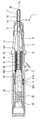
도 1은 본 발명에 따른 장치의 길이 방향 단면도이다.1 is a longitudinal sectional view of a device according to the invention.
도 1에 도시된 바와 같이, 본 발명에 따른 분사 장치(1)는 내부 연소 엔진의 연소 챔버 또는 공기 흡입관(양쪽 모두 미도시)으로 연료를 분사하도록 한다.As shown in FIG. 1, the
상기 분사 장치는 앞 부분(front part)(10) 및 뒷 부분(rear part)(11)의 두 부분으로 이루어진 원통형 본체를 포함한다. 상기 부분들은 같은 축을 가지고, 슬리브(12)와 같은 방법으로 스크류-체결에 의해 함께 결합된다.The injection device comprises a cylindrical body consisting of two parts, a
상기 원통형 본체의 상기 앞 부분(10)은 상기 앞 부분(10)의 일 단부에 상기 원통형 본체와 같은 축을 가지는 구멍(bore)(15)과 시트(seat)(14)를 갖는다. 니들(2)은 상기 구멍(15)에 슬라이딩 가능하도록 설치된다. 그것은 상기 시트(14)를 가지는 밸브로서 행동하는 헤드(20)를 포함한다. 통로(passage)(16)는 상기 시트(14)까지 연료의 루트를 정하기 위해 상기 구멍(15)과 상기 니들(2) 사이의 공간에 형성된다. 상기 통로(16)는 연결 포트(connection port)(17)로부터 상기 원통형 본체 내로 연결되는 덕트(13)로부터 공급된다.The
상기 원통형 본체의 상기 뒷부분(11)은 상기 원통형 본체의 상기 축을 따라 슬라이딩될 수 있도록 설치된 관 모양 슬리브 튜브(37)를 포함한다. 상기 관 모양 슬리브 튜브(27)는 상기 원통형 본체에 포함되어 있는 제1 관절(shoulder)(110)과 상기 관 모양 슬리브 튜브(37)에 포함되어 있는 제2 관절(shoulder)(370)을 받치고 있는 슬리브 튜브 스프링(4)에 의해 뒤쪽으로 힘을 받는다.The
상기 헤드(20)에 대한 반대쪽 단부에서 상기 니들(2)은 탄성 와셔(elastic washer)(33)에 받쳐져 있는 플랜지(flange)(21)를 갖는다. 상기 탄성 와셔(33)는 또한 상기 탄성 와셔(33)를 통해 상기 니들(2)로 상기 슬리브 튜브 스프링(4)의 장 력을 전달하는 것과 같은 방법으로 상기 관 모양 슬리브 튜브(37)에 포함되어 있는 제3 관절(371)에 대해 가압되고 따라서 상기 시트(14)에 대해서 상기 니들의 상기 헤드(20)를 가압한다.At the opposite end to the
상기 니들(2)의 상기 후방 연속부에서, 상기 분사 장치(1)는 전기활성(electroactive) 재료 액츄에이터(3) 및 중량체(34)를 포함한다. 기술한 상기 실시예에서 상기 액츄에이터(3)는 코일(31) 및 강자성 재료의 튜브(32)에 의해 둘러싸진 자기-변형성(magnetostrictive) 재료의 로드(30)를 포함한다. 예를 들어, 상기 로드(3)는 (상표명으로 등록된)터페놀(Terfenol)로 만들어진다. 상기 로드(30)는 상기 슬리브 튜브(37)로 나사 체결된 접관(nipple)(36)에 대해 가압하는 프리로딩(preloading) 스프링(35)을 포함하고 상기 로드(30)에 대해 상기 중량체(34)를 가압하는 경향이 있는 프리로딩(preloading) 장치에 의해 압축된다. 강자성 재료의 상기 튜브(32)는 상기 로드(30)의 동일한 단부에서 상기 중량체(34)의 상기 단부에서 생성되는 가이드 실린터(340) 상에 눌러진다.In the rear continuous portion of the
상기 니들(2)의 길이는 그것을 구성하는 재료와 결합하여, 상기 니들이 10부터 30kHz 까지 연장되는 범위 내의 여기 주파수에서 축 방향 진동(oscillation)을 받을 때 공진되는 것과 같은 방법으로 결정된다. 공진은 상기 니들이 상기 니들의 진동의 자연 주파수에 근접한 주파수에서 가압될 때 얻어진다. 상기 니들이 l의 길이를 가진다면, fn=(2n+1)C/(4*l)과 같은 다수의 자연 주파수들이 존재한다. 여기서, n은 양의 정수이거나 0이고, C는 니들을 구성하는 재료 내에서의 음속이다.The length of the
상기 중량체(34)는 임피던스가 상기 니들의 임피던스보다 큰 재료로 만들어 진다. 상기 중량체(34)는 예를 들어 텅스텐으로 만들어지는 반면, 상기 니들(2)은 철이나 티타늄으로 만들어진다. 상기 임피던스는 수식 Z=ρC에 의해 정의된다. 여기서, r은 kg.m-3단위의 밀도이고, C는 m.s-1 단위의 상기 재료 내에서의 음속이다. 상기 임피던스는 또한
분사 단계가 수행될 때, 선택된 여기 주파수에서 실제로 지속적인 신호와 주기적인 신호는 상기 분사 기간 동안 상기 액츄에이터에 가해진다. 이렇게 하기 위해서, 상기 코일(31)에 상기 지속적인 신호와 상기 주기적인 신호를 운반하는 전류(current)를 공급하기 위한 수단(means)(미도시)이 사용된다. 그 결과, 상기 로드(30)는 상기 여기 주파수에서 상기 지속적인 신호와 상기 주기적인 신호의 강도에 따라 평균적으로 신장된다. 상기 다른 선형 임피던스들을 지탱하면서, 상기 로드(30)는 상기 중량체(34)에 안착되어, 상기 니들(2)이 움직이고 진동하도록 하게 된다. 상기 니들의 상기 헤드(20)에 준 상기 운동은, 예를 들어, 20 내지 30 ㎛의 평균 변위와 10 내지 20 ㎛ 정도의 진동이다.When the injection step is performed, a substantially continuous and periodic signal at the selected excitation frequency is applied to the actuator during the injection period. To do this, means (not shown) for supplying the
본 발명은 예로써 기술된 실시예에 제한되지 아니한다. 상기 액츄에이터는 압전(壓電)(piezoelectric) 재료로 만들어진 로드를 사용하여 제조될 수 있다.The invention is not limited to the embodiments described by way of example. The actuator can be manufactured using a rod made of piezoelectric material.
본 발명은 연료 분사 장치, 상세하게는 내부 연소 엔진을 위한 연료 분사 장치에 사용될 수 있다.The invention can be used in fuel injectors, in particular fuel injectors for internal combustion engines.
Claims (10)
Translated fromKoreanApplications Claiming Priority (3)
| Application Number | Priority Date | Filing Date | Title |
|---|---|---|---|
| FR0508182AFR2889257B1 (en) | 2005-08-01 | 2005-08-01 | FUEL INJECTION DEVICE AND METHOD FOR CONTROLLING SUCH A DEVICE |
| FR0508182 | 2005-08-01 | ||
| PCT/FR2006/050740WO2007015022A1 (en) | 2005-08-01 | 2006-07-20 | Fuel injecting device and method for controlling said device |
Publications (2)
| Publication Number | Publication Date |
|---|---|
| KR20080043790A KR20080043790A (en) | 2008-05-19 |
| KR101129016B1true KR101129016B1 (en) | 2012-03-28 |
Family
ID=36021719
Family Applications (1)
| Application Number | Title | Priority Date | Filing Date |
|---|---|---|---|
| KR1020087004631AActiveKR101129016B1 (en) | 2005-08-01 | 2006-07-20 | Fuel injecting device and method for controlling said device |
Country Status (10)
| Country | Link |
|---|---|
| US (1) | US7784708B2 (en) |
| EP (1) | EP1913253B1 (en) |
| KR (1) | KR101129016B1 (en) |
| CN (1) | CN101233313B (en) |
| AT (1) | ATE425354T1 (en) |
| DE (1) | DE602006005682D1 (en) |
| ES (1) | ES2320041T3 (en) |
| FR (1) | FR2889257B1 (en) |
| RU (1) | RU2439362C2 (en) |
| WO (1) | WO2007015022A1 (en) |
Families Citing this family (9)
| Publication number | Priority date | Publication date | Assignee | Title |
|---|---|---|---|---|
| FR2918123A1 (en)* | 2007-06-27 | 2009-01-02 | Renault Sas | FLUID INJECTION DEVICE. |
| FR2922964B1 (en) | 2007-10-31 | 2009-11-20 | Renault Sas | RESONANT NEEDLE FLUID INJECTION DEVICE FOR INTERNAL COMBUSTION ENGINE |
| FR2924176A3 (en) | 2007-11-27 | 2009-05-29 | Renault Sas | Fluid e.g. pressurized liquid fuel, injecting device e.g. injector, for internal combustion engine, has actuator for placing resonant needle in axial oscillation, and bellow forming sealing between mobile element and end of nozzle tip |
| DE102008054591A1 (en)* | 2008-12-12 | 2010-06-17 | Robert Bosch Gmbh | Decoupling element for a fuel injection device |
| FR2941746A1 (en) | 2009-02-02 | 2010-08-06 | Renault Sas | DEVICE FOR INJECTING LIQUID, IN PARTICULAR FUEL, WITH ELECTROACTIVE ACTUATOR. |
| FR2949247B1 (en)* | 2009-08-24 | 2011-09-16 | Renault Sa | SYSTEM FOR MOUNTING A RESONANT NEEDLE INJECTION DEVICE. |
| FR2978301B1 (en) | 2011-07-18 | 2013-08-02 | Renault Sa | METHOD FOR ASSEMBLING AN ULTRASONIC TRANSDUCER AND TRANSDUCER OBTAINED BY THE METHOD |
| RU2540347C2 (en)* | 2013-01-24 | 2015-02-10 | Федеральное государственнное бюджетное образовательное учреждение высшего профессионального образования "Ярославский государственный технический университет" | Ice electrically-controlled fuel injector |
| US10119507B1 (en)* | 2017-07-17 | 2018-11-06 | GM Global Technology Operations LLC | Rotating fuel injector assembly |
Citations (4)
| Publication number | Priority date | Publication date | Assignee | Title |
|---|---|---|---|---|
| US4749892A (en) | 1983-04-25 | 1988-06-07 | Colt Industries Inc. | Spring arrangement with additional mass for improvement of the dynamic behavior of electromagnetic systems |
| US6474572B1 (en) | 1999-04-13 | 2002-11-05 | Hitachi, Ltd. | Fuel-injection valve |
| US20040183405A1 (en) | 2001-10-02 | 2004-09-23 | D'ouvenou Lorand | Actuator unit comprising at least two actuator elements |
| US20060278735A1 (en) | 2003-05-09 | 2006-12-14 | Renault S.A.S. | Fluid injection device |
Family Cites Families (12)
| Publication number | Priority date | Publication date | Assignee | Title |
|---|---|---|---|---|
| SU75137A1 (en)* | 1948-03-16 | 1948-11-30 | Л.А. Верте | Liquid fuel nozzle |
| SU1366678A1 (en)* | 1986-05-11 | 1988-01-15 | Д.С.Ценев | Electrically-controlled pump-nozzle |
| SU1386733A1 (en)* | 1986-10-30 | 1988-04-07 | Киевский Автомобильно-Дорожный Институт Им.60-Летия Великой Октябрьской Социалистической Революции | Electromagnetic injector with control unit for injecting fuel into internal combustion engine |
| DE3936619A1 (en)* | 1989-11-03 | 1991-05-08 | Man Nutzfahrzeuge Ag | METHOD FOR INJECTING A FUEL INTO THE COMBUSTION CHAMBER OF AN AIR COMPRESSING, SELF-IGNITION ENGINE, AND APPARATUS FOR CARRYING OUT THIS METHOD |
| DE19546033A1 (en)* | 1995-12-09 | 1997-06-12 | Bosch Gmbh Robert | Fuel injection valve for internal combustion engines |
| RU2150019C1 (en)* | 1999-03-16 | 2000-05-27 | Пинский Феликс Ильич | Electrohydraulic injector |
| DE19912665A1 (en)* | 1999-03-20 | 2000-09-21 | Bosch Gmbh Robert | Fuel injector |
| US6318646B1 (en)* | 1999-03-26 | 2001-11-20 | MAGNETI MARELLI S.p.A. | Fuel injector |
| US7021569B1 (en)* | 2000-01-26 | 2006-04-04 | Hitachi, Ltd. | Fuel injection valve |
| RU2201522C2 (en)* | 2000-09-25 | 2003-03-27 | ООО НПК "Базальт" | Internal combustion engine electrically controlled nozzle |
| US6543700B2 (en)* | 2000-12-11 | 2003-04-08 | Kimberly-Clark Worldwide, Inc. | Ultrasonic unitized fuel injector with ceramic valve body |
| DE10232193A1 (en)* | 2002-07-16 | 2004-02-05 | Robert Bosch Gmbh | Fuel injector |
- 2005
- 2005-08-01FRFR0508182Apatent/FR2889257B1/ennot_activeExpired - Fee Related
- 2006
- 2006-07-20EPEP06794493Apatent/EP1913253B1/enactiveActive
- 2006-07-20ESES06794493Tpatent/ES2320041T3/enactiveActive
- 2006-07-20WOPCT/FR2006/050740patent/WO2007015022A1/enactiveApplication Filing
- 2006-07-20USUS11/997,648patent/US7784708B2/ennot_activeExpired - Fee Related
- 2006-07-20ATAT06794493Tpatent/ATE425354T1/ennot_activeIP Right Cessation
- 2006-07-20KRKR1020087004631Apatent/KR101129016B1/enactiveActive
- 2006-07-20RURU2008107952/06Apatent/RU2439362C2/ennot_activeApplication Discontinuation
- 2006-07-20CNCN2006800283803Apatent/CN101233313B/enactiveActive
- 2006-07-20DEDE602006005682Tpatent/DE602006005682D1/enactiveActive
Patent Citations (4)
| Publication number | Priority date | Publication date | Assignee | Title |
|---|---|---|---|---|
| US4749892A (en) | 1983-04-25 | 1988-06-07 | Colt Industries Inc. | Spring arrangement with additional mass for improvement of the dynamic behavior of electromagnetic systems |
| US6474572B1 (en) | 1999-04-13 | 2002-11-05 | Hitachi, Ltd. | Fuel-injection valve |
| US20040183405A1 (en) | 2001-10-02 | 2004-09-23 | D'ouvenou Lorand | Actuator unit comprising at least two actuator elements |
| US20060278735A1 (en) | 2003-05-09 | 2006-12-14 | Renault S.A.S. | Fluid injection device |
Also Published As
| Publication number | Publication date |
|---|---|
| CN101233313A (en) | 2008-07-30 |
| RU2439362C2 (en) | 2012-01-10 |
| KR20080043790A (en) | 2008-05-19 |
| EP1913253B1 (en) | 2009-03-11 |
| WO2007015022A1 (en) | 2007-02-08 |
| DE602006005682D1 (en) | 2009-04-23 |
| EP1913253A1 (en) | 2008-04-23 |
| ATE425354T1 (en) | 2009-03-15 |
| FR2889257A1 (en) | 2007-02-02 |
| CN101233313B (en) | 2011-02-16 |
| US7784708B2 (en) | 2010-08-31 |
| FR2889257B1 (en) | 2007-11-02 |
| RU2008107952A (en) | 2009-09-10 |
| ES2320041T3 (en) | 2009-05-18 |
| US20080315019A1 (en) | 2008-12-25 |
Similar Documents
| Publication | Publication Date | Title |
|---|---|---|
| KR101129016B1 (en) | Fuel injecting device and method for controlling said device | |
| US8038080B2 (en) | Fuel injector for an internal combustion engine | |
| JP4942749B2 (en) | Fuel injection device for internal combustion engines | |
| CA1166835A (en) | Method of producing a fuel injector | |
| SE445244B (en) | ULTRA SOUND INJECTOR FOR DIESEL ENGINE | |
| Lee et al. | Dynamic analysis and control of an active engine mount system | |
| US9677520B2 (en) | Valve for metering fluid | |
| US9385300B2 (en) | Magnetostrictive actuator | |
| KR20140017628A (en) | Method for determining the force conditions at the nozzle needle of a directly driven piezo injector | |
| US20150268127A1 (en) | Resonance testing machine | |
| JP2000310105A (en) | Gas exchange valve device with electromagnetic actuator | |
| JP2010531410A (en) | Fluid ejection device | |
| CN101802385B (en) | The electromagnetic valve | |
| US10519909B2 (en) | Valve for metering a fluid | |
| US8099225B2 (en) | Fuel injection system and method for injecting fuel | |
| KR20100038399A (en) | Fluid injection device | |
| US9038602B2 (en) | Mounting system for a resonating needle injection device | |
| JP2635041B2 (en) | Fuel injection device | |
| JPH09310655A (en) | Fuel injection device | |
| JP2008111411A (en) | Fuel injector vibration reduction device | |
| JP2006177267A (en) | Fuel injection valve and control method for fuel injection valve | |
| JP3879542B2 (en) | Damping device and control method thereof | |
| JP2007092725A (en) | Fuel injection noise reduction device | |
| JP2007085265A (en) | Vibration reduction device | |
| JP2011047292A (en) | Fuel injection device |
Legal Events
| Date | Code | Title | Description |
|---|---|---|---|
| PA0105 | International application | St.27 status event code:A-0-1-A10-A15-nap-PA0105 | |
| P11-X000 | Amendment of application requested | St.27 status event code:A-2-2-P10-P11-nap-X000 | |
| P13-X000 | Application amended | St.27 status event code:A-2-2-P10-P13-nap-X000 | |
| PG1501 | Laying open of application | St.27 status event code:A-1-1-Q10-Q12-nap-PG1501 | |
| A201 | Request for examination | ||
| P11-X000 | Amendment of application requested | St.27 status event code:A-2-2-P10-P11-nap-X000 | |
| P13-X000 | Application amended | St.27 status event code:A-2-2-P10-P13-nap-X000 | |
| PA0201 | Request for examination | St.27 status event code:A-1-2-D10-D11-exm-PA0201 | |
| E701 | Decision to grant or registration of patent right | ||
| PE0701 | Decision of registration | St.27 status event code:A-1-2-D10-D22-exm-PE0701 | |
| GRNT | Written decision to grant | ||
| PR0701 | Registration of establishment | St.27 status event code:A-2-4-F10-F11-exm-PR0701 | |
| PR1002 | Payment of registration fee | St.27 status event code:A-2-2-U10-U12-oth-PR1002 Fee payment year number:1 | |
| PG1601 | Publication of registration | St.27 status event code:A-4-4-Q10-Q13-nap-PG1601 | |
| R18-X000 | Changes to party contact information recorded | St.27 status event code:A-5-5-R10-R18-oth-X000 | |
| FPAY | Annual fee payment | Payment date:20150305 Year of fee payment:4 | |
| PR1001 | Payment of annual fee | St.27 status event code:A-4-4-U10-U11-oth-PR1001 Fee payment year number:4 | |
| FPAY | Annual fee payment | Payment date:20160303 Year of fee payment:5 | |
| PR1001 | Payment of annual fee | St.27 status event code:A-4-4-U10-U11-oth-PR1001 Fee payment year number:5 | |
| FPAY | Annual fee payment | Payment date:20170302 Year of fee payment:6 | |
| PR1001 | Payment of annual fee | St.27 status event code:A-4-4-U10-U11-oth-PR1001 Fee payment year number:6 | |
| FPAY | Annual fee payment | Payment date:20180302 Year of fee payment:7 | |
| PR1001 | Payment of annual fee | St.27 status event code:A-4-4-U10-U11-oth-PR1001 Fee payment year number:7 | |
| PR1001 | Payment of annual fee | St.27 status event code:A-4-4-U10-U11-oth-PR1001 Fee payment year number:8 | |
| FPAY | Annual fee payment | Payment date:20200305 Year of fee payment:9 | |
| PR1001 | Payment of annual fee | St.27 status event code:A-4-4-U10-U11-oth-PR1001 Fee payment year number:9 | |
| PR1001 | Payment of annual fee | St.27 status event code:A-4-4-U10-U11-oth-PR1001 Fee payment year number:10 | |
| P22-X000 | Classification modified | St.27 status event code:A-4-4-P10-P22-nap-X000 | |
| PR1001 | Payment of annual fee | St.27 status event code:A-4-4-U10-U11-oth-PR1001 Fee payment year number:11 | |
| R18-X000 | Changes to party contact information recorded | St.27 status event code:A-5-5-R10-R18-oth-X000 | |
| PR1001 | Payment of annual fee | St.27 status event code:A-4-4-U10-U11-oth-PR1001 Fee payment year number:12 | |
| PN2301 | Change of applicant | St.27 status event code:A-5-5-R10-R11-asn-PN2301 | |
| PN2301 | Change of applicant | St.27 status event code:A-5-5-R10-R14-asn-PN2301 | |
| PR1001 | Payment of annual fee | St.27 status event code:A-4-4-U10-U11-oth-PR1001 Fee payment year number:13 | |
| PR1001 | Payment of annual fee | St.27 status event code:A-4-4-U10-U11-oth-PR1001 Fee payment year number:14 | |
| R18-X000 | Changes to party contact information recorded | St.27 status event code:A-5-5-R10-R18-oth-X000 |