KR101121210B1 - Seal ring and stern tube sealing apparatus - Google Patents
Seal ring and stern tube sealing apparatusDownload PDFInfo
- Publication number
- KR101121210B1 KR101121210B1KR1020117002269AKR20117002269AKR101121210B1KR 101121210 B1KR101121210 B1KR 101121210B1KR 1020117002269 AKR1020117002269 AKR 1020117002269AKR 20117002269 AKR20117002269 AKR 20117002269AKR 101121210 B1KR101121210 B1KR 101121210B1
- Authority
- KR
- South Korea
- Prior art keywords
- lip
- tip
- key
- seal ring
- arm
- Prior art date
- Legal status (The legal status is an assumption and is not a legal conclusion. Google has not performed a legal analysis and makes no representation as to the accuracy of the status listed.)
- Active
Links
- 238000007789sealingMethods0.000titleclaimsdescription36
- 230000002093peripheral effectEffects0.000claimsabstractdescription13
- 239000013535sea waterSubstances0.000claimsdescription14
- 238000000034methodMethods0.000claims4
- 230000002159abnormal effectEffects0.000abstractdescription25
- 230000002028prematureEffects0.000abstractdescription12
- 230000004323axial lengthEffects0.000description11
- 230000000052comparative effectEffects0.000description11
- 229920001971elastomerPolymers0.000description10
- 238000012360testing methodMethods0.000description9
- 239000000463materialSubstances0.000description6
- 238000005299abrasionMethods0.000description5
- 230000002411adverseEffects0.000description5
- 238000005452bendingMethods0.000description4
- 238000010586diagramMethods0.000description4
- 239000003921oilSubstances0.000description4
- 230000001154acute effectEffects0.000description3
- 230000007423decreaseEffects0.000description3
- 230000000694effectsEffects0.000description3
- 238000003780insertionMethods0.000description3
- 230000037431insertionEffects0.000description3
- 239000010687lubricating oilSubstances0.000description3
- XLYOFNOQVPJJNP-UHFFFAOYSA-NwaterSubstancesOXLYOFNOQVPJJNP-UHFFFAOYSA-N0.000description3
- YCKRFDGAMUMZLT-UHFFFAOYSA-NFluorine atomChemical compound[F]YCKRFDGAMUMZLT-UHFFFAOYSA-N0.000description2
- 229920000459Nitrile rubberPolymers0.000description2
- 230000005856abnormalityEffects0.000description2
- 239000000806elastomerSubstances0.000description2
- 239000011737fluorineSubstances0.000description2
- 229910052731fluorineInorganic materials0.000description2
- 230000009545invasionEffects0.000description2
- 230000033001locomotionEffects0.000description2
- 238000011056performance testMethods0.000description2
- 229920002449FKMPolymers0.000description1
- 230000015572biosynthetic processEffects0.000description1
- 230000000903blocking effectEffects0.000description1
- 230000006835compressionEffects0.000description1
- 238000007906compressionMethods0.000description1
- 238000012790confirmationMethods0.000description1
- 238000002474experimental methodMethods0.000description1
- 229920001973fluoroelastomerPolymers0.000description1
- -1for exampleSubstances0.000description1
- 230000020169heat generationEffects0.000description1
- 230000008595infiltrationEffects0.000description1
- 238000001764infiltrationMethods0.000description1
- 239000000314lubricantSubstances0.000description1
- 230000000149penetrating effectEffects0.000description1
- 230000002265preventionEffects0.000description1
- 230000037303wrinklesEffects0.000description1
Images


Classifications
- B—PERFORMING OPERATIONS; TRANSPORTING
- B63—SHIPS OR OTHER WATERBORNE VESSELS; RELATED EQUIPMENT
- B63H—MARINE PROPULSION OR STEERING
- B63H23/00—Transmitting power from propulsion power plant to propulsive elements
- B63H23/32—Other parts
- B63H23/36—Shaft tubes
- F—MECHANICAL ENGINEERING; LIGHTING; HEATING; WEAPONS; BLASTING
- F16—ENGINEERING ELEMENTS AND UNITS; GENERAL MEASURES FOR PRODUCING AND MAINTAINING EFFECTIVE FUNCTIONING OF MACHINES OR INSTALLATIONS; THERMAL INSULATION IN GENERAL
- F16J—PISTONS; CYLINDERS; SEALINGS
- F16J15/00—Sealings
- F16J15/16—Sealings between relatively-moving surfaces
- F16J15/32—Sealings between relatively-moving surfaces with elastic sealings, e.g. O-rings
- F16J15/3204—Sealings between relatively-moving surfaces with elastic sealings, e.g. O-rings with at least one lip
- F16J15/3208—Sealings between relatively-moving surfaces with elastic sealings, e.g. O-rings with at least one lip provided with tension elements, e.g. elastic rings
- F16J15/3212—Sealings between relatively-moving surfaces with elastic sealings, e.g. O-rings with at least one lip provided with tension elements, e.g. elastic rings with metal springs
- B—PERFORMING OPERATIONS; TRANSPORTING
- B63—SHIPS OR OTHER WATERBORNE VESSELS; RELATED EQUIPMENT
- B63H—MARINE PROPULSION OR STEERING
- B63H23/00—Transmitting power from propulsion power plant to propulsive elements
- B63H23/32—Other parts
- B63H23/321—Bearings or seals specially adapted for propeller shafts
- B—PERFORMING OPERATIONS; TRANSPORTING
- B63—SHIPS OR OTHER WATERBORNE VESSELS; RELATED EQUIPMENT
- B63H—MARINE PROPULSION OR STEERING
- B63H23/00—Transmitting power from propulsion power plant to propulsive elements
- B63H23/32—Other parts
- B63H23/34—Propeller shafts; Paddle-wheel shafts; Attachment of propellers on shafts
- F—MECHANICAL ENGINEERING; LIGHTING; HEATING; WEAPONS; BLASTING
- F16—ENGINEERING ELEMENTS AND UNITS; GENERAL MEASURES FOR PRODUCING AND MAINTAINING EFFECTIVE FUNCTIONING OF MACHINES OR INSTALLATIONS; THERMAL INSULATION IN GENERAL
- F16J—PISTONS; CYLINDERS; SEALINGS
- F16J15/00—Sealings
- F16J15/16—Sealings between relatively-moving surfaces
- F16J15/32—Sealings between relatively-moving surfaces with elastic sealings, e.g. O-rings
- F16J15/3204—Sealings between relatively-moving surfaces with elastic sealings, e.g. O-rings with at least one lip
- F16J15/322—Sealings between relatively-moving surfaces with elastic sealings, e.g. O-rings with at least one lip supported in a direction perpendicular to the surfaces
- F—MECHANICAL ENGINEERING; LIGHTING; HEATING; WEAPONS; BLASTING
- F16—ENGINEERING ELEMENTS AND UNITS; GENERAL MEASURES FOR PRODUCING AND MAINTAINING EFFECTIVE FUNCTIONING OF MACHINES OR INSTALLATIONS; THERMAL INSULATION IN GENERAL
- F16J—PISTONS; CYLINDERS; SEALINGS
- F16J15/00—Sealings
- F16J15/16—Sealings between relatively-moving surfaces
- F16J15/32—Sealings between relatively-moving surfaces with elastic sealings, e.g. O-rings
- F16J15/3244—Sealings between relatively-moving surfaces with elastic sealings, e.g. O-rings with hydrodynamic pumping action
- F—MECHANICAL ENGINEERING; LIGHTING; HEATING; WEAPONS; BLASTING
- F16—ENGINEERING ELEMENTS AND UNITS; GENERAL MEASURES FOR PRODUCING AND MAINTAINING EFFECTIVE FUNCTIONING OF MACHINES OR INSTALLATIONS; THERMAL INSULATION IN GENERAL
- F16J—PISTONS; CYLINDERS; SEALINGS
- F16J15/00—Sealings
- F16J15/16—Sealings between relatively-moving surfaces
- F16J15/40—Sealings between relatively-moving surfaces by means of fluid
Landscapes
- Engineering & Computer Science (AREA)
- General Engineering & Computer Science (AREA)
- Mechanical Engineering (AREA)
- Chemical & Material Sciences (AREA)
- Combustion & Propulsion (AREA)
- Ocean & Marine Engineering (AREA)
- Physics & Mathematics (AREA)
- Fluid Mechanics (AREA)
- Sealing Devices (AREA)
- Sealing With Elastic Sealing Lips (AREA)
Abstract
Translated fromKoreanDescription
Translated fromKorean본 발명은, 선미관의 선외 측에 설치된 케이싱 부재 내를 관통하는 선박용의 추진축과 케이싱 부재 사이에 설치되어, 해수가 선내 측에 침수하는 것을 방지하는 시일 링 및 그것을 이용한 선미관 시일 장치에 관한 것이다.
The present invention relates to a seal ring provided between a propulsion shaft for ships passing through a casing member provided on the outboard side of the stern tube and a casing member, and to prevent seawater from submerging on the inboard side, and a stern tube sealing device using the same. .
종래부터, 고무나 엘라스토머로 이루어지는 시일 링이 선미관 시일 장치에 이용되어 왔다.Conventionally, the seal ring which consists of rubber | gum and an elastomer has been used for the stern tube sealing apparatus.
예를 들면, 특허 문헌 1(특개 2000-238694호 공보)에는, 도 7에 나타낸 바와 같이, 선미관(01)을 관통하는 추진축(프로펠러축)(02)에 장착된 라이너(03)에 미끄럼운동하는 탄성 부재로 이루어지는 립형의 시일 링(04, 05, 06)이, 복수의 하우징 부재(07)에 끼워지도록 배치되어, 선미 측에 배치한 제 1 시일 링(04)과, 이에 인접하는 제 2 시일 링(05)에 의해서 제 1 선미 환상 공간(08)을 형성하는 동시에, 제 2 시일 링(05)과 제 3 시일 링(06)에 의해 제 2 선미 환상 공간(09)을 형성하도록 하여, 해수의 침수나 이물의 침입, 및 선내 측의 윤활유의 누설을 방지하는 선미관 시일 장치(010)가 나타내어져 있다.For example, Patent Document 1 (Japanese Patent Laid-Open No. 2000-238694), as shown in FIG. 7, slides on a
이 시일 링(04, 05, 06)의 단면 형상으로서는, 도 8에 도시한 형상이 나타내어져 있다.
As a cross-sectional shape of this
[선행 기술 문헌][Prior Art Literature]
[특허 문헌][Patent Document]
[특허 문헌 1] 특개 2000-238694호 공보
[Patent Document 1] Japanese Patent Application Laid-Open No. 2000-238694
선미관 시일 장치에 이용되는 시일 링은, 선미관의 선외 측에 설치된 케이싱의 내주 측에 형성된 환상 홈에 감합하는 시일 외주부와, 프로펠러축의 외주나 프로펠러축에 외감(外嵌)한 라이너 외주면에 밀접하는 시일 립부에 의해 구성되어, 시일 외주부의 케이싱으로의 감합 부분에는, 조임 여유가 마련되어 조립할 수 있게 되어 있다.The seal ring used for the stern tube sealing device is closely related to a seal outer peripheral portion that fits into an annular groove formed on the inner circumferential side of the casing provided on the outboard side of the stern tube, and an outer peripheral surface of the liner that is external to the outer circumference of the propeller shaft or the propeller shaft. It is comprised by the seal lip part to be made, and the fastening space is provided in the fitting part to the casing of a seal outer peripheral part, and can be assembled.
이 때문에, 시일 외주부의 케이싱으로의 감합에 임하여, 비틀림이나 물림이 생기거나, 장착 후의 온도 변화에 의해, 시일 외주부가 변형하면, 시일 립부의 접촉 응력이 변화하여, 시일성에 악영향을 줄 우려가 있었다.
For this reason, in the fitting to the casing of the seal outer peripheral portion, if the seal outer peripheral portion deforms due to a torsion or bite, or a temperature change after mounting, the contact stress of the seal lip portion may change, which may adversely affect the sealability. .
또한, 프로펠러축 외주면이나 라이너 외주면으로 밀착하는 시일 립부를 지지하는 완부의 강성이 약하면, 시일 립부가 라이너 외주면에 적절한 응력 상태로 접촉하지 못하고, 시일 립부의 미끄럼운동면이, 완전히 맞닿은 상태를 일으켜서 조기 이상 마모가 생기기 쉽고, 또한 이상 마모에 의한 미끄럼운동 발열에 의해 고무 물성의 연화와 변형을 일으켜서 스펀지화하여 기포 발생(블리스터)이나 내부 크랙의 발생의 우려가 있었다. 이 때문에, 시일 링의 시일 립의 단면 형상이나 시일 립부를 지지하는 완부의 강성에 대해 여러 가지의 연구가 이루어지고 있다.
In addition, if the stiffness of the arm supporting the seal lip in close contact with the propeller shaft outer circumferential surface or the liner outer circumferential surface is weak, the seal lip does not come into contact with the liner outer circumferential surface in an appropriate stress state, and the sliding surface of the seal lip portion is brought into full contact, thus prematurely Abnormal abrasion is likely to occur, and softening and deformation of the rubber properties due to abnormal heat generation cause softening and deformation of the rubber properties, resulting in sponge formation, which may cause bubbles (blisters) or internal cracks. For this reason, various studies are made about the cross-sectional shape of the seal lip of a seal ring, and the rigidity of the arm part which supports a seal lip part.
상기 특허 문헌 1에 개시되어 있는 시일 링의 단면 형상은, 도 8에 나타낸 바와 같이, 시일 링(04)이 프로펠러축(02)의 라이너(03)와 접촉하는 미끄럼운동면에, 프로펠러축(02)의 회전 시에 제 1 선미 환상 공간(08) 내의 물을 고압 측의 선외에 강제적으로 송출하게 하도록 하는 미소한 요철(011)을 라이너의 미끄럼운동면(012)에 다수 마련하고, 이 요철(011)에 의해, 프로펠러축(02)의 회전 시에 이송 작용을 적극적으로 발생시키는 것이다.As shown in FIG. 8, the cross-sectional shape of the seal ring disclosed in the said
따라서, 이 특허 문헌 1에는, 시일 링의 외주부가 케이싱의 내주에 형성되는 홈에 안정적으로 감합하는 시일 링의 단면 형상이나, 시일 링의 외주부를 케이싱에 감합하기 쉬운 단면 형상이나, 더욱이 시일 립부의 접촉 응력을 적정 상태로 유지하여, 시일 립부와 프로펠러 샤프트의 미끄럼운동면을 개입시켜 누설이나 시일 립부의 조기 이상 마모 등을 방지하여 시일성을 향상하는 것까지는 개시되어 있지 않다.
Therefore,
따라서, 본 발명은, 이러한 문제를 감안하여 이루어진 것으로서, 시일 립부의 접촉 응력이 누설이나 조기 이상 마모 등을 일으키지 않는 적정 상태로 유지되도록 설정되어, 시일성을 유지하면서 내구성을 향상하는 동시에, 또한 케이싱의 환상 홈에 감합하는 시일 외주부의 장착성을 향상하여, 시일 립부의 접촉 응력을 안정화시키는 시일 링 및 그것을 이용한 선미 환형 시일 장치를 제공하는 것을 목적으로 한다.
Therefore, this invention is made | formed in view of such a problem, and it is set so that the contact stress of a seal lip part may be maintained in the appropriate state which does not cause leakage, early abnormal abrasion, etc., and it improves durability while maintaining sealing property, and also a casing An object of the present invention is to provide a seal ring for improving the attachability of a seal outer peripheral portion to be fitted into an annular groove of a ring, and to stabilize the contact stress of the seal lip portion, and a stern annular seal device using the seal ring.
상기 과제를 해결하기 위해, 제 1 발명은, 선미관의 선외 측에 설치된 케이싱 부재 내를 관통하는 선박용 추진축과, 상기 케이싱 부재 사이에 설치되고, 해수가 선내 측에 침수하는 것을 방지하는 시일 링으로서, 추진축 방향의 단면 형상이, 케이싱의 내주에 형성된 환상 홈에 감합하는 키부와, 상기 키부로부터 추진 축심을 향해 직경방향으로 신장하는 힐부와, 상기 힐부의 선단으로부터 일정한 경사 각도를 가져서 직경방향 내측에 신장하는 동시에 케이싱 측에 형성된 백업 부재에 의해 내측이 지지를 받는 완부와, 상기 완부의 선단에 형성되어 추진축의 외주면 혹은 추진축에 외감되는 라이너 부재의 외주면에 밀접하는 립부를 구비하는 시일 링에 있어서, 상기 키부의 최상부는 축방향 두께의 중심을 정점으로서 반경방향 외측에 산 형상으로 형성되는 동시에, 키부로부터 힐부에는 축방향 두께가 얇아지도록 키부의 정면 측과 배면 측에 각각 단차부를 갖고, 상기 단차부의 내경은 키부의 정면 측보다 배면 측이 크게 형성되고, 상기 립부의 립 선단은 반경방향 내측으로 산 형상으로 송출하고, 립부에는 립 선단을 추진축 측으로 가압하는 환상 스프링이 감합하는 스프링 홈이 형성되고, 상기 스프링 홈의 중심이 상기 립 선단보다 립 배면 측에 립 배면 폭의 추진축 방향 길이의 10%의 범위 내로 오프셋되어 설치되는 것을 특징으로 한다.
MEANS TO SOLVE THE PROBLEM In order to solve the said subject, 1st invention is provided between the ship propulsion shaft which penetrates in the casing member provided in the outboard side of the stern tube, and the said casing member, and is a seal ring which prevents seawater from submerging inboard. The cross-sectional shape in the direction of the propulsion shaft has a key portion fitted into an annular groove formed in the inner circumference of the casing, a heel portion extending in the radial direction from the key portion toward the propulsion axis center, and a radial inclination angle from the tip of the heel portion. A seal ring having an arm extending along with being supported by a backing member formed on the casing side, and a lip formed at the distal end of the arm and close to the outer circumferential surface of the propulsion shaft or the outer circumferential surface of the liner member that is wound around the propulsion shaft. The uppermost part of the key part is formed in a mountain shape on the radially outer side with the center of the axial thickness as a vertex. At the same time, the heel portion from the key portion has a step portion on the front side and the back side of the key portion so that the axial thickness becomes thinner, and the inner diameter of the step portion is larger than the front side of the key portion, and the lip tip of the lip portion has a radius. A spring groove is formed in which the annular spring presses the lip tip toward the propulsion shaft side, and the center of the spring groove is provided on the lip rear side of the lip rear side than the lip tip side. It is characterized in that the offset is installed in the range of 10%.
이러한 제 1 발명에 의하면, 상기 키부의 정부는 축방향 두께의 중심을 정점으로서 반경방향 외측에 산 형상으로 형성되는 동시에, 키부로부터 힐부에는 축방향 두께가 얇아지도록 키부의 정면 측과 배면 측에 각각 단차부를 갖고, 상기 단차부의 내경은 키부의 정면 측보다 배면 측이 크게 형성되기 때문에, 시일 링의 키부의 환상 홈으로의 장착성이 향상하여, 장착 시에 키부가 잘 감입되지 않게 물려 시일 링이 변형하는 것이 방지된다. 그 결과, 키부가 변형하는 동시에, 립부의 접촉 응력이 변화하여, 시일성에 악영향을 주는 것이 방지된다.
According to this first invention, the top portion of the key portion is formed in a mountain shape radially outward with the center of the axial thickness as a vertex, and on the front side and the back side of the key portion so that the axial thickness becomes thinner from the key portion to the heel portion, respectively. Since the inner side of the step portion has a larger step side than the front side of the key portion, the inner side of the step portion is formed to be larger, so that the sealability of the seal ring into the annular groove of the key portion is improved, and the seal ring is deformed so as to prevent the key portion from being penetrated well during mounting. Is prevented. As a result, while the key portion deforms, the contact stress of the lip portion changes, and it is prevented from adversely affecting the sealability.
즉, 배면측의 높이가 낮기 때문에, 정면 측을 앞방향으로서 시일 링을 케이싱 내의 환상 홈에 압입(press)하기 쉬워진다. 따라서, 조립하기 쉽고, 선박이 도크 등에서 추진축을 뽑지 않고 축 상에서 시일 링의 교환이 용이하게 된다.
That is, since the height of the back side is low, it becomes easy to press the seal ring into the annular groove in the casing with the front side facing forward. Therefore, it is easy to assemble, and the ship becomes easy to replace the seal ring on the shaft without removing the propulsion shaft from the dock or the like.
또한, 이러한 제 1 발명에 의하면, 상기 립부의 립 선단은 반경방향 내측에 산 형상으로 송출하고, 립부에는 립 선단을 추진축 측으로 가압하는 환상 스프링이 감합하는 스프링 홈이 형성되어 상기 스프링 홈의 중심이 상기 립 선단보다 립 배면 측에 립 배면 폭의 추진축 방향 길이의 10%의 범위 내로 오프셋되어 설치되므로, 상기 환상 홈에 키부가 감합되고, 추진축의 외주면 혹은 추진축에 외감되는 라이너 부재의 외주면에 상기 립부를 밀접시킨 세트 상태 때에는, 립 선단으로부터 립 배면폭의 추진축 방향 길이의 대략 20%의 위치에 환상 스프링이 위치되어 립 선단측에서의 접촉 응력을 높일 수 있고, 립부의 밀봉 성능을 향상할 수 있다. 또한, 립 선단측에서의 접촉 응력을 높일 수 있는 것에 의해서, 립 배면의 접촉의 완전히 맞닿은 상태도 생기기 어려워서 이상 마모의 발생도 방지된다.Further, according to the first invention, the lip tip of the lip portion is sent radially inwardly in the form of a mountain, and the lip portion is formed with a spring groove to which an annular spring for pressing the lip tip toward the propulsion shaft side is fitted to form a center of the spring groove. Since the lip is offset and installed within the range of 10% of the propelling axis direction length of the lip rear width from the lip rear side, the lip is fitted to the annular groove, and the lip is formed on the outer circumferential surface of the propulsion shaft or the outer circumferential surface of the liner member that is wound around the propulsion shaft. In the set state in which the parts are in close contact, the annular spring is positioned at a position approximately 20% of the length of the lip rearward width from the lip tip to increase the contact stress at the lip tip side, and improve the sealing performance of the lip. In addition, since the contact stress at the lip tip side can be increased, it is difficult to generate a fully contact state of the contact on the lip back surface, and the occurrence of abnormal wear is also prevented.
따라서, 시일 립부의 접촉 응력이 누설이나 조기 이상 마모 등을 일으키지 않는 적정 상태에 유지되어, 시일성을 유지하면서 내구성을 향상할 수 있다.
Therefore, the contact stress of the seal lip portion is maintained in an appropriate state without causing leakage, premature abnormal wear, or the like, and durability can be improved while maintaining the sealability.
또한, 제 1 발명에 있어서, 바람직하게는, 상기 립부의 추진축 방향에 대한 립 정면각(β)을 립 배면각(α) 보다 크게 형성하고, 립 정면각(β)이 45~55°의 범위로, 또한 립 배면각(α)이 25~30°의 범위로 설정되면 좋다.
Moreover, in 1st invention, Preferably, the lip front angle (beta) with respect to the propulsion axis direction of the said lip part is formed larger than the lip back angle (alpha), and the lip front angle (beta) is the range of 45-55 degrees. In addition, the lip back angle α may be set within a range of 25 to 30 degrees.
립 배면각(α) 및 립 정면각(β)이 상기 설정 범위보다 커지면, 립 선단이 예각이 되어, 진동이 큰 선박에서는 립 선단의 접촉면 폭의 부족을 일으켜서 정면 측으로부터 배면 측으로의 해수의 누설이나, 배면 측으로부터 정면 측으로의 윤활유의 누설이 생기기 쉬워진다. 또한, 반대로, 립 배면각(α) 및 립 정면각(β)이 설정 범위보다 작아지면, 립 선단이 둔각이 되어, 립 선단의 접촉면 폭이 커져서, 과잉의 접촉을 일으켜서 접촉 압력을 확보하지 못하여 시일성이 악화되는 동시에 조기 이상 마모가 생기기 쉬워진다.
If the lip back angle α and the lip front angle β are larger than the above-mentioned setting range, the tip of the lip becomes an acute angle, and in ships with large vibrations, shortage of the contact surface width of the lip tip causes leakage of seawater from the front side to the back side. In addition, leakage of lubricant from the back side to the front side tends to occur. On the contrary, if the lip back angle α and the lip front angle β are smaller than the set range, the lip tip becomes obtuse, and the contact surface width of the lip tip increases, causing excessive contact and failing to secure contact pressure. At the same time, the sealing property deteriorates, and early abnormal wear easily occurs.
따라서, 상기 범위로 설정하는 것에 의해 립 선단에 발생하는 이상 현상을 억제하여, 시일성을 유지하면서 내구성을 향상할 수 있다. 특히, 이와 같이 립 선단 정면측 및 배면측의 각도를 설정하는 것에 의해, 상기 환상 스프링의 오프셋 위치와 더불어, 립 선단에 있어서의 접촉 응력이 적정하게 유지되어 시일성을 향상할 수 있다.
Therefore, by setting in the said range, the abnormal phenomenon which arises at a lip | tip tip can be suppressed, and durability can be improved, maintaining sealing property. In particular, by setting the angles of the lip tip front side and the back side in this manner, the contact stress at the lip tip can be properly maintained along with the offset position of the annular spring, thereby improving the sealability.
또한, 제 1 발명에 있어서, 바람직하게는, 상기 백업 부재의 선단과 상기 완부의 접촉 위치에 있어서의 완부 두께(H)와, 상기 접촉 위치로부터 립 선단까지의 상기 경사 각도 방향에 있어서의 팔 거리(L)가, H3/L4=(10~30)×10-4(1/mm)의 관계를 만족하면 좋다.
Moreover, in 1st invention, Preferably, arm thickness (H) in the contact position of the front-end | tip of the said backup member and said arm part, and the arm distance in the said inclination-angle direction from the said contact position to a lip front-end | tip (L) may satisfy the relationship of H3 / L4 = (10 to 30) × 10−4 (1 / mm).
이와 같이, H3/L4=(10~30)×10-4(1/mm)의 관계를 만족하도록 설정하는 것은, 즉, H3/L4을 파라미터로서 이용하여 완부로부터 립부에 걸친 강성을 설정한다.Thus, setting to satisfy the relationship of H3 / L4 = (10-30) × 10-4 (1 / mm), that is, stiffness from the arm to the lip using H3 / L4 as a parameter Set.
백업 부재의 접촉 위치로부터 앞이 캔틸레버인 받침대에 있어서의 휨을 일으키는 부분이므로, 립 선단의 휨량(V)을, 캔틸레버 받침대의 휨 식(1)을 이용하여 나타내고, 립 선단이 적절한 접촉 응력에 의해 접촉하는 완부 및 립부의 강성을, 휨량을 요구하는 식(1)의, H3/L4을 파라미터로서 이용하여 평가한다.Since it is the part which causes the bending in the base which is a cantilever from the contact position of a backup member, the deflection amount (V) of a lip tip is shown using the bending formula (1) of a cantilever base, and a lip tip contacts by appropriate contact stress. The rigidity of the arm part and the lip part to be evaluated is evaluated by using H3 / L4 of the formula (1) which requires the deflection amount as a parameter.
V=K1(WL4/EI)=K2(WL4/EH3) ???(1)V = K1 (WL4 / EI) = K2 (WL4 / EH3 ) ??? (1)
W:시일 링 정면 측에 걸린 압력, K1, K2:정수, E:신장 탄성률(사용 재료, 예를 들면 불소고무의 신장 탄성률을 이용한다)
W: Pressure applied to the seal ring front side, K1 , K2 : Constant, E: Elongation modulus (use elongation modulus of used material, for example, fluorine rubber)
시험 결과를 기초하여, H3/L4=(10~30)×10-4(1/mm)의 관계를 찾아냈다. 그 결과, 이 범위로 설정하는 것에 의해, 시일 립부의 미끄럼운동면이 과잉으로 접촉(완전히 맞닿음)하여 조기 이상 마모를 일으킬 수 없는 적정 상태로 유지되어, 시일성을 유지하면서 내구성이 향상할 수 있다.
Based on the test results, a relationship of H3 / L4 = (10 to 30) × 10−4 (1 / mm) was found. As a result, by setting in this range, the sliding surface of the seal lip portion is kept in an appropriate state in which excessive contact (complete contact) and no premature wear occurs, and the durability can be improved while maintaining the sealability. have.
또한, 제 1 발명에 있어서, 바람직하게는, 상기의 H3/L4을 파라미터로 하는 것이 아니라, 상기 환상 홈에 키부가 감합되어 추진축의 외주면 혹은 추진축에 외감되는 라이너 부재의 외주면에 상기 립부가 밀접된 세트 상태에 있어서, 시일 링의 정면 측을 배면 측보다 높게 하여 정면 측과 배면 측과의 차압을 약 0.15 MPa로 했을 때에 상기 립 선단의 접촉 폭이 2~3mm가 되도록 상기 완부 및 립부의 강성이 설정되도록 해도 괜찮다.
Further, in the first invention, preferably, the lip portion is formed on the outer circumferential surface of the propulsion shaft or the outer circumferential surface of the liner member that is not fitted to the H3 / L4 as a parameter and fits the key portion to the annular groove. In the close set state, when the front side of the seal ring is made higher than the back side and the differential pressure between the front side and the back side is about 0.15 MPa, the arm portion and the lip portion are arranged so that the contact width of the lip tip is 2-3 mm. The stiffness may be set.
이와 같이, 접촉 폭을 설정하는 것에 의해, 휨 식으로부터 설정한 H3/L4을 이용하는 일 없이, 직접적으로 접촉 폭을 규정하는 것으로, 립부의 미끄럼운동면이 과잉으로 접촉(정답)하여 조기 이상 마모를 일으킬 수 없는 적정 상태로 유지되어, 시일성을 유지하면서 내구성을 향상할 수 있다. 또한, 이 2~3mm의 접촉 폭의 최적치는 시험에 의해 미리 확인한 값이다.
In this way, by setting the contact width, the contact width is directly defined without using H3 / L4 set from the warp expression, and the sliding surface of the lip portion is excessively contacted (corrected). It can be maintained in an appropriate state that can not cause wear, and durability can be improved while maintaining sealability. In addition, the optimum value of this 2-3 mm contact width is the value previously confirmed by the test.
다음에, 제 2 발명은, 선미관 시일 장치에 관한 것으로서, 선미관의 선외 측에 설치된 케이싱 부재 내를 관통하는 선박용 추진축과, 상기 케이싱 부재 사이에 설치되고, 해수가 선내 측에 침수하는 것을 방지하는 시일 링을 구비하며, 상기 시일 링의 추진축 방향의 단면 형상이, 케이싱의 내주에 형성된 환상 홈에 감합하는 키부와, 상기 키부로부터 추진 축심을 향해 직경방향으로 신장하는 힐부와, 상기 힐부의 선단으로부터 일정한 경사 각도를 가져서 직경방향 내측으로 신장하는 동시에 케이싱 측에 형성된 백업 부재에 의해 내측이 지지되는 완부와, 상기 완부의 선단에 형성되어 추진축의 외주면 혹은 추진축에 외감되는 라이너 부재의 외주면에 밀접하는 립부에 의해 구성되는 선미관 시일 장치에 있어서, 상기 키부의 최상부는 축방향 두께의 중심을 정점으로서 반경방향 외측에 산 형상으로 형성되는 동시에, 키부로부터 힐부에는 축방향 두께가 얇아지도록 키부의 정면 측과 배면 측에 각각 단차부를 갖고, 상기 단차부의 내경은 키부의 정면 측보다 배면 측이 크게 형성되고, 키부는 상기 환상 홈에 감합하면 단단히 체결되는 동시에, 배면측의 상기 단차부와 상기 환상 홈 사이에는 직경방향으로 공간이 형성되고, 상기 립부의 립 선단은 반경방향 내측에 산 형상으로 돌출하고, 립부에는 힙 선단을 추진축 측으로 가압하는 환상 스프링이 감합하는 스프링 홈이 형성되고, 상기 스프링 홈의 중심이 상기 립 선단보다 립 배면 측에 립 배면 폭의 추진축 방향 길이의 10%의 범위 내로 오프셋되어 설치되는 것을 특징으로 한다.
Next, the second invention relates to a stern tube sealing device, and is provided between a ship propulsion shaft passing through a casing member provided on the outboard side of the stern tube and the casing member, and prevents seawater from invading the inboard side. And a key portion in which a cross-sectional shape in the direction of the propulsion axis of the seal ring fits into an annular groove formed in the inner circumference of the casing, a heel portion extending in the radial direction from the key portion toward the propulsion axis, and the tip of the heel portion. Extends inwardly in the radial direction with a constant inclination angle from the arm and is supported by the backing member formed on the casing side, and close to the outer circumferential surface of the propulsion shaft or the outer circumferential surface of the liner member formed at the tip of the arm and wound around the propulsion shaft. In the stern tube sealing device constituted by the lip portion, the uppermost portion of the key portion has a center of axial thickness. As the apex is formed in the shape of a mountain on the outer side in the radial direction, the heel portion has a stepped portion on the front side and the back side of the key portion so that the axial thickness becomes thinner, and the inner diameter of the stepped portion is the back side than the front side of the key portion. It is largely formed, and the key portion is firmly fastened when the key portion is fitted to the annular groove, and a space is formed in the radial direction between the stepped portion on the rear side and the annular groove, and the lip tip of the lip portion is in a radial shape inwardly in the radial direction. Protruding, the lip portion is formed with a spring groove for fitting the annular spring for pressing the hip end toward the propulsion shaft side, the center of the spring groove is within the range of 10% of the length of the prop shaft direction of the lip rear width than the lip end side It is characterized in that the offset is installed.
이러한 제 2 발명에 의하면, 상기 제 1 발명으로 설명한 시일 링의 작용 효과를 갖는 선미관 시일 장치를 얻을 수 있다.
According to this second invention, the stern tube sealing device having the effect of the sealing ring described in the first invention can be obtained.
또한, 제 2 발명에 있어서, 바람직하게는, 상기 립부의 추진축 방향에 대한 립 정면각(β)을 립 배면각(α) 보다 크게 형성하고, 립 정면각(β)이 45~55°의 범위로, 또한 립 배면각(α)이 25~30°의 범위로 설정되면 좋다.
Moreover, in 2nd invention, Preferably, the lip front angle (beta) with respect to the propulsion axis direction of the said lip part is formed larger than the lip back angle (alpha), and the lip front angle (beta) is the range of 45-55 degrees. In addition, the lip back angle α may be set within a range of 25 to 30 degrees.
또한, 제 2 발명에 있어서, 바람직하게는, 상기 백업 부재의 선단과 상기 완부와의 접촉 위치에 있어서의 완부 두께(H)와, 상기 접촉 위치로부터 립 선단까지의 상기 경사 각도 방향에 있어서의 팔 거리(L)가, H3/L4=(10~30)×10-4(1/mm)의 관계를 만족하면 좋다.
Moreover, in 2nd invention, Preferably, the arm thickness H in the contact position of the front-end | tip of the said backup member and the said arm, and the arm in the said inclination-angle direction from the said contact position to a lip front-end | tip The distance L may satisfy the relationship of H3 / L4 = (10 to 30) × 10−4 (1 / mm).
또한, 제 2 발명에 있어서, 바람직하게는, 상기 환상 홈에 키부가 감합되고, 추진축의 외주면 혹은 추진 축에 외감되는 라이너 부재의 외주면에 상기 립부가 밀접된 세트 상태에 있어서, 시일 링의 정면 측을 배면 측보다 높게 하여 정면 측과 배면 측과의 차압을 약 0.15 MPa로 했을 때에 상기 립 선단의 접촉 폭이 2~3mm가 되도록 상기 완부 및 립부의 강성이 설정되면 좋다.
Further, in the second invention, the front side of the seal ring is preferably in the set state in which the key portion is fitted to the annular groove and the lip portion is in close contact with the outer circumferential surface of the propulsion shaft or the outer circumferential surface of the liner member that is wound around the propulsion shaft. When the pressure difference between the front side and the back side is set to about 0.15 MPa, the rigidity of the arm portion and the lip portion may be set so that the contact width of the lip tip is 2-3 mm.
이러한 구성에 의해, 상기 제 1 발명으로 설명한 시일 링을 갖춘 선미관 시일 장치를 얻을 수 있다.
With such a configuration, the stern tube sealing device with the seal ring described in the first invention can be obtained.
또한, 제 2 발명에 있어서, 바람직하게는, 상기 환상 홈의 양측 벽의 직경방향 거의 중앙부에, 환상의 릴리프 홈이 형성되어 있으면 좋다.Moreover, in 2nd invention, Preferably, the annular relief groove should just be formed in the substantially center part of the radial direction of the both side walls of the said annular groove.
이와 같이, 상기 환상 홈의 양측 벽의 직경방향 거의 중앙부에, 환상의 릴리프 홈이 형성되어 있는 것에 의해, 케이싱의 환상 홈에 키부를 밀어 넣어 감합하는 경우에, 키부의 측벽의 일부가 상기 릴리프 홈에 비집고 들어가기 위해, 키부 체결 후의 내경 측으로의 이동이 억제되고, 키부의 환상 홈 내에서의 감합 상태의 위치 결정이 되어, 키부의 위치가 안정화한다.
As described above, when an annular relief groove is formed in a substantially central portion of the both sides of the annular groove in the radial direction, a part of the side wall of the key portion is formed by pushing the key portion into the annular groove of the casing. In order to fit in, the movement to the inner diameter side after the key part is fastened is suppressed, positioning of the fitting state in the annular groove of the key part is stabilized, and the position of the key part is stabilized.
제 1 발명에 의하면, 시일 링의 키부의 장착성이 향상하여, 장착 시의 키부의 변형이 방지되고, 그 결과 키부가 변형하는 동시에, 립부의 접촉 응력이 변화하여, 시일성에 악영향을 주는 것이 방지된다. 또한, 시일 링을 케이싱 내의 환상 홈에 압입하기 쉬워져서, 추진축을 뽑지 않고 축 상에서 시일 링의 교환이 가능하게 된다.
According to the first invention, the mountability of the key portion of the seal ring is improved, and the deformation of the key portion at the time of mounting is prevented, and as a result, the key portion is deformed and the contact stress of the lip portion is changed, thereby preventing the adverse effect on the sealability. . In addition, the seal ring can be easily pushed into the annular groove in the casing, so that the seal ring can be replaced on the shaft without removing the propulsion shaft.
더욱이, 제 1 발명에 의하면, 립부의 립 선단은 반경 방향 내측에 산 형상으로 돌출하고, 립부에는 립 선단을 추진축 측으로 가압하는 환상 스프링이 감합하는 스프링 홈이 형성되고, 상기 스프링 홈의 중심이 상기 립 선단보다 립 배면 측에 립 배면 폭의 추진축 방향 길이의 10%의 범위 내로 오프셋되어 설치되므로, 상기 환상 홈에 키부가 감합되고, 추진축의 외주면 혹은 추진축에 외감되는 라이너 부재의 외주면에 상기 립부를 밀접시킨 세트 상태일 때에는, 립 선단으로부터 립 배면 폭의 추진축 방향 길이의 대략 20%의 위치에 환상 스프링이 위치되어 립 선단 측에서의 접촉 응력을 높일 수 있고, 립부의 밀봉 성능을 향상할 수 있다. 또한, 립 선단 측에서의 접촉 응력을 높일 수 있는 것에 의해, 립 배면의 접촉의 완전히 맞닿은 상태도 생기기 어려워서 이상 마모의 발생도 방지된다.Furthermore, according to the first aspect of the invention, the lip tip of the lip portion protrudes in a radial shape inside the radial direction, and the lip portion is formed with a spring groove to which an annular spring for pressing the lip tip toward the propulsion shaft side is fitted, and the center of the spring groove is Since the lip is offset from the lip front end in the range of 10% of the length in the direction of the propulsion axis of the lip back width, the key part is fitted to the annular groove, and the lip part is formed on the outer circumferential surface of the propulsion shaft or the outer circumferential surface of the liner member that is wound around the propulsion shaft. In the close set state, the annular spring is positioned at a position approximately 20% of the length of the lip rearward width from the lip tip, whereby the contact stress at the lip tip side can be increased, and the sealing performance of the lip can be improved. In addition, since the contact stress at the lip tip side can be increased, a state where the contact of the lip back is completely brought into contact with each other is less likely to occur, and the occurrence of abnormal wear is also prevented.
따라서, 시일 립부의 접촉 응력이 누설이나 조기 이상 마모 등을 일으키지 않는 적정 상태로 유지되어, 시일성을 유지하면서 내구성을 향상할 수 있다.
Therefore, the contact stress of the seal lip portion is maintained in an appropriate state which does not cause leakage, premature abnormal wear, or the like, thereby improving durability while maintaining the sealability.
또한, 제 2 발명에 의하면, 상기 제 1 발명의 시일 링에 의해서 발휘되는 작용 효과를 갖는 선박의 선미관 시일 장치를 얻을 수 있다.
Moreover, according to 2nd invention, the stern tube sealing apparatus of the ship which has an effect which is exhibited by the said seal ring of 1st invention can be obtained.
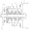
도 1은 실시예를 나타내는 시일 링을 구비한 선미관 시일 장치의 전체 구성도의 예이다.
도 2는 시일 링 단체의 형상을 나타내는 설명도이다.
도 3은 시일 링이 케이싱의 환상 홈에 장착된 상태를 나타내는 전체 구성도이다.
도 4는 립 선단의 배면각과 정면각과의 관계를 나타내는 도표이다.
도 5는 시일 링 세트 상태로의 회전 시험 결과를 나타낸다. (a)는 그 시험 결과를 나타내는 도표이고, (b)는 시험 조건을 나타내는 설명도이다.
도 6은 환상 스프링의 오프셋 배치에 의한 접촉면압의 변화를 나타내는 설명도이다.
도 7은 종래 기술의 설명도이다.
도 8은 종래 기술의 설명도이다.BRIEF DESCRIPTION OF THE DRAWINGS It is an example of the whole block diagram of the stern tube sealing apparatus provided with the seal ring which shows an Example.
It is explanatory drawing which shows the shape of a seal ring single body.
3 is an overall configuration diagram showing a state in which the seal ring is mounted in the annular groove of the casing.
4 is a chart showing the relationship between the back angle and the front angle of the lip tip.
5 shows the results of the rotational test in the seal ring set state. (a) is a chart which shows the test result, (b) is explanatory drawing which shows test conditions.
It is explanatory drawing which shows the change of contact surface pressure by the offset arrangement of an annular spring.
7 is an explanatory diagram of a prior art.
8 is an explanatory diagram of a prior art.
이하, 본 발명을 도면에 나타낸 실시예를 이용하여 상세하게 설명한다. 단, 이 실시예에 기재되어 있는 구성 부품의 치수, 재질, 형상, 그 상대 배치 등은 특히 특정적인 기재가 없는 한, 본 발명의 범위를 이들에만 한정하는 취지는 아니다.
EMBODIMENT OF THE INVENTION Hereinafter, this invention is demonstrated in detail using the Example shown in drawing. However, the dimensions, materials, shapes, relative arrangements, and the like of the component parts described in this embodiment are not intended to limit the scope of the present invention to only these unless otherwise specified.
도 1을 참조하여, 선미관 시일 장치의 전체 구성에 대해 설명한다. 선미관 시일 장치(1)는, 도 1에 나타낸 바와 같은 프로펠러(3)가 단부에 장착된 추진용 프로펠러축(추진축)(5)과, 선미관(7)으로부터 선외 측에 돌출하여 설치되어 내부에 프로펠러축(5)이 관통하는 케이싱(케이싱 부재)(9)과, 상기 케이싱(9)의 내주측과 프로펠러축(5)의 외주측 사이를 시일하는 시일 링(11)에 의해 구성되어 있다.With reference to FIG. 1, the whole structure of a stern tube sealing apparatus is demonstrated. The stern
프로펠러(3)에는 볼트(13)에 의해 프로펠러축(5)의 라이너(15)가 고정되어 있고, 라이너(15)의 몸통부는 프로펠러축(5)의 외주를 둘러싸서 프로펠러축(5)과 일체로 회전하게 되어 있다. 이 라이너(15)의 몸통부 외주에는 3개의 립형의 시일 링(11a, 11b, 11c)의 립이 미끄럼 접촉하고 있다. 또한, 최선미 측에는, 어망 방지 링(17)이 장착되어, 어망 등의 해수중의 이물이 비집고 들어가는 것을 막고 있다.
The
케이싱(9)은, 복수의 케이싱(9a~9e)이 적층 상태로 중첩하여 볼트(19)에 의해 일체로 선미관(7)에 고정되고, 시일 링(11a, 11b, 11c) 각각은, 케이싱(9b~9e)에 끼우도록 하여 유지되어 있다. 최선미 측에 배치되는 제 1 시일 링(11a)과, 그 근처의 제 2 시일 링(11b)은 립이 해수 측을 향하여, 해수가 선내 측에 유입하는 것을 막는 기능을 하고 있다. 선내 측에 가장 가까운 제 3 시일 링(11c)은 립을 선내 측을 향하여, 선내 측의 윤활유가 선외로 빠져나오는 것을 막고 있다.
The
또한, 제 1 시일 링(11a)과 제 2 시일 링(11b)에 의해, 제1 선미 환상 공간(21)을 형성하고, 제 2 시일 링(11b)과 제 3 시일 링(11c)에 의해, 제 2 선미 환상 공간(23)을 형성하고, 제 3 시일 링(11c)의 선미관(7) 측의 제 3 선미 환상 공간(25)은 도시하지 않는 저유 탱크에 연통하고 있다. 이들 선미 환상 공간에는 취항하기 전에 미리 기름을 충전하여 밀봉 상태로 된다.
Moreover, the 1st stern
이들 시일 링(11a, 11b, 11c)은, 고무 또는 엘라스토머의 탄성 부재로 이루어지고, 고무 재료로서는, 내수, 내유에 강한 불소 고무(예를 들면, 듀퐁사 제의 상품명 바이톤), 또는 니트릴 고무(NBR)에 의해 형성되어 있다.
These
시일 링(11)은, 원환(링) 형상을 하고, 중심의 중공 부분에 라이너(15)가 삽입되게 되어 있고, 원환 부분의 단면 형상은 일정 단면 형상을 가지고, 프로펠러축(5) 방향의 단면 형상을 도 2에 나타낸다.The
도 2와 같이, 시일 링(11)[여기에서는 제 1 시일 링(11a)에 대해 설명하지만, 다른 제 2 시일 링(11b), 제 3 시일 링(11c)에 대해서도 같은 단면 형상을 가지고 있음]은, 선미관(7)의 선체 외측에 고정되어 프로펠러축(5)을 둘러싸도록 형성되는 케이싱(케이싱 부재)(9)의 내주에 형성된 환상 홈(27)(도 3 참조)에 감합하는 키부(29)와, 상기 키부(29)로부터 프로펠러축(5)의 중심선을 향해 직경방향으로 신장하는 힐부(31)와, 상기 힐부(31)의 선단으로부터 정면 측으로 일정한 경사 각도를 가져서 신장하는 완부(33)와, 상기 완부(33)의 선단에 형성되어 라이너(15)의 외주면에 밀접하는 립부(35)에 의해 구성되어 있다. 이하 각 부에 대하여 상세하게 설명한다.
As shown in Fig. 2, the seal ring 11 (the
(키부)(Kibu)
키부(29)의 최상부는 축방향 두께의 중심(T)을 정점으로서 반경방향 외측에 산 형상으로 형성되어 있다. 예를 들면, 양측으로 균등하게 대략 15도의 경사각을 가지고 있다. 이와 같이, 균등인 산 형상으로 하는 것으로, 키부(29)를 케이싱(9) 내의 환상 홈(27) 내에, 밀어 넣어 사이에 둘 때에, 고무는 압축되어, 산 형상의 최상부는, 양방향으로 밀리게 되므로, 즉 2방향으로 압축률의 공간이 있는 것으로, 키부(29)의 환상 홈(27) 내의 중심 위치가 스스로 정해져서, 키부(29)의 감합 상태가 안정된다.
The uppermost part of the
또한, 키부(29)로부터 힐부(31)에는 축방향 두께가 얇아지도록 키부(29)의 정면 측(A)과 배면 측(B)에 각각 단차부(37a, 37b)가 형성되고, 단차부(37a, 37b)는 R형상으로 형성되어 있다.Further, the
또한, 배면 측(B)의 단차부(37b)의 내경은, 정면 측(A)의 단차부(37a)의 내경보다 크게 형성되어 있다. 즉, 키부(29)의 높이가, 정면 측(A)보다 배면 측(B)이 낮게 형성되어 있다. 구체적으로는, 키부(29)의 정면측의 높이가, 7~15mm에 대해, 배면 측의 높이가 5.5~11mm로 형성되어 있다. 내경으로 말하면 배면 측(B)의 단차부(37b)의 내경(37bd)이 정면 측(A)의 단차부(37a)의 내경(37ad)보다 1.5~4mm 크게 형성되고 있다.
Moreover, the inner diameter of the
이와 같이 배면 측의 높이를 정면 측 높이의 70~80%로 하는 것에 의해, 케이싱(9)의 환상 홈(27)에, 키부(29)를 삽입할 때에[도 3 점선 화살표(Y) 방향으로 키부(29)를 밀어 넣을 때에], 배면 측의 높이가 낮기 때문에, 배면 측의 단차부(37b)가 잘 환상 홈(27) 내에 끼워져서, 물리는 일 없이 조립이 간단하고 또 확실하게 된다. 이 정면 측과 배면 측과의 높이 관계는 실험적으로 삽입하기 쉬움과 삽입 후의 안정성에서 설정되어 있다.Thus, by making the height of the back side into 70 to 80% of the height of the front side, when inserting the
즉, 배면 측의 높이가 너무 낮으면, 키부(29)를 배면 측에서 막는 면적이 감소하기 때문에, 조립 후의 키부(29)의 위치가 불안정하게 된다. 이 때문에 상기한 바와 같은 일정한 범위가 필요하다.
That is, if the height of the rear side is too low, the area of blocking the
또한, 키부(29)의 환상 홈(27)으로의 조립 시에 키부(29)가 잘 끼워지지 않고 물려 키부(29)가 변형하여 한층 더 립부(35)의 접촉면이 변형하는 것이 방지된다. 그 결과로서 립부(35)의 접촉 응력이 변화하여 시일성에 악영향을 주는 것이 방지된다.
In addition, when assembling the
더욱이, 배면측의 높이가 낮기 때문에, 정면 측을 앞쪽으로 하여 시일 링(11a)을 케이싱(9) 내의 환상 홈(27)에 눌러 넣기가 용이해지므로, 선박이 도크 등에서 프로펠러축(5)을 뽑지 않고, 프로펠러(3)와 라이너(15)를 떼어낸 상태에서 시일 링(11a)의 교환이 용이하게 된다.
Moreover, since the height of the rear side is low, it is easy to push the
(완부)(Arm)
힐부(31)의 하부 선단으로부터 정면 측(A)을 향해 일정한 경사 각도(θ)를 가져서 신장하는 완부(33)가 형성되어 있다. 경사 각도(θ)는 25~30도의 범위로 형성된다. 이 완부(33)의 선단에는 라이너(15)의 외주면에 밀접하는 립부(35)가 형성된다.The
또한, 이 완부(33)의 도중 위치까지, 시일 링(11a)이 케이싱(9) 내에 세트되어 정면 측으로부터 해수압이 작용했을 때에 케이싱(9)에 형성된 백업 부재(49)에 당접하여 직경방향으로 내측으로부터 지지되도록 되어 있다.
In addition, the
(립부)(Lip)
립부(35)의 립 선단(39)은 반경방향 내측에 산 형상으로 돌출하여 형성되어 있다. 또한, 립부(35)에는 립 선단(39)을 라이너(15)에 가압하는 환상 스프링(41)(도 3 참조)이 감합하는 반원 단면 형상의 스프링 홈(43)이 형성되고, 상기 스프링 홈(43)의 중심(P)는, 립 선단(39)보다 립 배면 측에 립 배면 폭(45)의 프로펠러 축방향 길이(45a)에 대해, 대략 10%의 범위 내로 오프셋(47) 되어 설치되어 있다. 즉, 도 2의 립 배면 폭(45)의 축방향 길이(45a)에 대한 오프셋(47)이 대략 10%의 범위 내로 위치되어 있다. 구체적으로는, 립 배면 폭(45)의 축방향 길이가 8~12mm에 대해, 오프셋량이 0.3~1.0 mm(3~9%)으로 설정된다.
The
이와 같이, 시일 링(11a)이 프리 상태[시일 링(11a)을 케이싱(9) 내에 조립하지 않는 단체의 상태를 말함]에 있어서, 스프링 홈(43)의 중심(P)이 립 선단(39)보다 립 배면 측에 립 배면 폭(45)의 프로펠러 축방향 길이(45a)의 대략 10%의 범위 내로 오프셋(47) 되어 설치되므로, 케이싱(9)의 환상 홈(27)에 키부(29)가 감합되고, 라이너(15)의 외주면에 립부(35)를 밀접시킨 세트 상태에 있어서, 립 선단(39)으로부터 립 배면 측에 립 배면 폭(45)의 축방향 길이로 오프셋량이 1.5~2.5mm[립 배면 폭(45)의 축방향 길이가 8~12mm에 대해, 오프셋량이 1.5~2.5 mm(19~21%)]가 되도록 설정되어 있다.As described above, in the
따라서, 프리 상태에서는, 대략 10%의 범위 내로 오프셋 상태인 것이, 세트 상태에서는 대략 20%가 된다.
Therefore, in the free state, the offset state within the range of approximately 10% becomes approximately 20% in the set state.
따라서, 시일 링(11a)을 라이너(15) 외주면에 세트한 상태에 있어서도 립 선단(39)으로부터 대략 20%의 위치에 환상 스프링(41)이 위치되므로, 립 배면 폭(45) 중 립 선단(39) 측에서 접촉 응력을 높일 수 있고, 립부(35)의 밀봉 성능을 향상할 수 있다. 또한, 립 선단(39) 측에서의 접촉 응력을 높일 수 있는 것에 의해, 립 배면의 접촉의 완전히 닿은 상태도 생기기 어려워 이상 마모의 발생도 방지된다.Therefore, even when the
따라서, 시일 립부의 접촉 응력이 누설이나 조기 이상 마모 등을 일으키지 않는 적정 상태로 유지되어, 시일성을 유지하면서 내구성을 향상할 수 있다.
Therefore, the contact stress of the seal lip portion is maintained in an appropriate state which does not cause leakage, premature abnormal wear, or the like, thereby improving durability while maintaining the sealability.
또한, 립부(35)의 립 선단(39)은 반경방향 내측에 산 형상으로 돌출하여, 프리 상태에서, 립 정면 측의 프로펠러 축방향에 대한 립 정면각(β)과 립 배면 측의 프로펠러 축방향에 대한 립 배면각(α)은, β>α의 관계를 가져서, β=45~55°의 범위, 또한 α=25~30°의 범위로 설정되어 있다.
In addition, the
립 정면각(β)이 립 배면각(α) 보다 크게 설정되어 있는 것은, 시일 링(11a)을 세트하여 정면 측에 해수의 압력이 작용했을 때에, 립 배면 측에 립부(35)가 쓰러지고, 립 배면 측에 미끄럼운동면이 형성되도록 하기 위한 것이다.The lip front angle β is set to be larger than the lip back angle α, when the
또한, 립 배면각(α) 및 립 정면각(β)이 설정 범위보다 커지면, 립 선단(39)이 예각이 되고, 진동이 큰 선박에서는 립 선단(39)의 접촉면 폭의 부족을 일으켜서 정면 측(A)으로부터 배면 측(B)(도 2, 도 3 참조)으로의 해수의 누설이나, 배면 측으로부터 정면 측으로의 윤활유의 누설이 생기기 쉬워진다. 또한, 반대로, 립 배면각(α) 및 립 정면각(β)이 설정 범위보다 작아지면, 립 선단이 둔각이 되고, 립 선단(39)의 접촉면 폭이 커져서, 과잉의 접촉을 일으켜 접촉 압력을 확보하지 못하여 시일성이 악화되는 동시에 조기 이상 마모가 생기기 쉬워진다.
In addition, when the lip back angle α and the lip front angle β are larger than the set range, the
구체적으로는, 도 4의 실시예 1에 나타낸 바와 같이, 프리 상태에서 45°≤β≤55°, 25°≤α≤30°의 범위로 하면, α, β의 범위의 경우에는, 시일 링(11a)을 세트하고, 후술하는 성능시험의 시험 조건(정면 측을 배면 측보다 약 0.15 MP 높게 한 상태)에 의해 확인했는데, 배면 측으로부터 정면 측으로의 누설량도, 미끄럼운동면의 이상 마모도 생기지 않았다.Specifically, as shown in Example 1 of Fig. 4, in the free state, in the range of 45 ° ≤β≤55 °, 25 ° ≤α≤30 °, in the case of α, β, the seal ring ( 11a) was set and confirmed by the test conditions (the state which made the front side about 0.15 MP higher than the back side) of the performance test mentioned later, and the leakage amount from the back side to the front side, and abnormal wear of the sliding surface also did not arise.
비교예 1과 같이 배면각(α)이, 20°≤α< 25°로 실시예 1 보다 작아지면, 립 선단(39)의 접촉면 폭이 커져서 이상 마모가 생기고, 비교예 2와 같이 실시예 1 보다 정면각(β)이, 55°<β≤ 65°으로 커지면, 립 선단이 예각이 되어 접촉면 폭이 작아져서 배면 측으로부터 정면 측으로의 누설량이 증대했다. 또한, 비교예 3과 같이, 배면각(α)을 20°≤α< 25°으로 작게 하고, 정면각(β)을 55°<β≤ 65°으로 크게 하면, 배면 측으로부터 정면 측으로의 누설, 및 미끄럼운동면의 이상 마모를 모두 낳기 쉬워졌다.
As in Comparative Example 1, when the back angle α becomes smaller than Example 1 at 20 ° ≦ α <25 °, the contact surface width of the
따라서, α, β를 상기 범위로 설정하는 것에 의해 립 선단(39)의 접촉면에 생기는 이상 현상을 억제하여, 시일성을 유지하면서 내구성을 향상할 수 있다. 특히, 이와 같이 립 선단(39)의 정면 측 및 배면 측의 각도를 설정하는 것으로 상기 환상 스프링(41)의 오프셋(47)과 더불어, 립 선단(39)의 접촉면에 있어서의 접촉 응력의 적정화 및 이상 마모를 방지할 수 있다.
Therefore, by setting α and β to the above ranges, abnormalities occurring on the contact surface of the
또한, 도 2, 3에 나타낸 바와 같이, 힐부(31)로부터 완부(33)에 걸쳐서, 완부(33)의 경사방향(θ)에 따라 신장하여 완부(33)를 하부에서 지지하는 백업 부재(49)가 케이싱(9)에 형성되어 있고, 이 백업 부재(49)의 선단과 완부(33)와의 접촉 위치(51)[상세하게는, 백업 부재(49)의 경사와 선단 측의 R부가 교차하는 교점 위치]에 있어서의 완부 두께(H)와, 접촉 위치(51)로부터 립 선단(39)까지의 경사 각도 방향에 있어서의 팔 거리(L)가, H3/L4=(10~30)×10-4(1/mm)의 관계를 만족하도록 설정되어 있다.
In addition, as shown in FIGS. 2 and 3, the backing
즉, 도 2에 나타낸 바와 같이, 백업 부재(49)의 선단과 완부(33)와의 접촉 위치(51)로부터 앞이 한쪽으로 치우친 지지받침대에 있어서의 휨을 일으키는 부분이므로, 립 선단(39)의 휨량(V)을, 한쪽 지지받침대의 휨 식(1)을 이용하여 나타내고, 립 선단(39)이 적절한 접촉 응력에 의해 접촉하는 완부(33) 및 립부(35)의 강성을, 휨량을 요구하는 식(1)의, H3/L4을 파라미터로서 이용하여 평가한다.
That is, as shown in FIG. 2, since the front part is warped in one side from the
V=K1(WL4/EI)=K2(WL4/EH3) ??? (1)V = K1 (WL4 / EI) = K2 (WL4 / EH3 ) ??? (One)
W:시일 링 정면 측에 결린 압력, K1, K2:정수, E:신장 탄성률(사용 재료, 예를 들면 불소 고무의 신장 탄성률을 이용한다)
W: Pressure at the seal ring front side, K1, K2: Integer, E: Elongation modulus (use elongation modulus of used material, for example, fluororubber)
시험 결과를 기초하여, H3/L4=(10~30)×10-4(1/mm)의 관계를 찾아냈다. 그 결과, 이 범위로 설정하는 것에 의해, 시일 립부의 미끄럼운동면이 과잉으로 접촉(완전히 맞닿음)하여 조기 이상 마모를 일으킬 수 없는 적정 상태로 유지되고, 시일성을 유지하면서 내구성이 향상할 수 있었다.
Based on the test results, a relationship of H3 / L4 = (10 to 30) × 10−4 (1 / mm) was found. As a result, by setting in this range, the sliding surface of the seal lip portion is kept in an appropriate state in which the sliding surface of the seal lip excessively contacts (completely abuts) and cannot cause premature wear and tear, and the durability can be improved while maintaining the sealability. there was.
또한, H3/L4을 파라미터로 하는 것이 아니라, 시일 링(11a)을 하우징(9) 내에 세트하여 라이너(15)를 장착한 상태로 하고, 시일 링(11a)의 정면 측(A)을 배면 측(B) 보다 높게 하여 정면 측(A)과 배면 측(B)과의 차압을 약 0.15 MPa일 때에 립 선단의 접촉면 폭이 2~3mm가 되도록 완부(33) 및 립부(35)의 강성이 설정되도록 해도 괜찮다.In addition, instead of using H3 / L4 as a parameter, the
이와 같이 접촉면 폭을 설정하는 것에 의해, 립부(35)의 미끄럼운동면이 과잉으로 접촉(완전히 맞닿음)하여 조기 이상 마모를 일으킬 수 없는 적정 상태로 유지되고, 시일성을 유지하면서 내구성을 향상할 수 있다.By setting the contact surface width in this way, the sliding surface of the
즉, 상기 H3/L4=(10~30)×10-4(1/mm)의 관계를 유지하도록 완부(3) 및 립부(35)의 강성을 설정하더라도, 립 선단의 접촉면 폭이 소정의 조건의 아래에서 일정 범위를 만족하도록 완부(33) 및 립부(35)의 강성을 설정하더라도, 마찬가지로 적절한 접촉 응력의 설정이 가능해진다.
That is, even if the rigidity of the
또한, 백업 부재(49)의 선단 위치, 즉 백업 부재(49)의 길이(B)는, 완부(33)의 길이(U)와 두께(H) 사이에, B/(U+H)=60~71%의 관계를 가지며, 이 범위 내로 설정되어 있다.In addition, the tip position of the
따라서, 상기 H3/L4의 범위의 설정에 더하여, 백업 부재(49)의 선단 위치의 범위를 설정하는 것에 의해, 완부(33)의 강성을 보다 적정 상태로 유지할 수 있게 된다.
Therefore, in addition to setting the range of H3 / L4 , by setting the range of the tip position of the
(케이싱으로의 세트 상태)(Set state in the casing)
도 3에 나타낸 바와 같이, 하우징(9)의 환상 홈(27)에 키부(29)가 감합되고, 라이너(15)의 외주면에 립부(35)를 밀접시킨 세트 상태에 있어서는, 완부(33)와 백업 부재(49)란, c의 간극이 대략 평행하게 형성되고, 백업 부재(49)의 선단과 완부(33)로부터 립부(35)에 걸치는 R부와의 사이에는, m의 간극이 형성되도록 세트된다. 또한, 도 4에 나타낸 바와 같은 립 배면각은 α'이 된다.As shown in FIG. 3, in the set state in which the
시일 링(11a)의 정면 측에 해수의 압력이 작용하면, 립부(35) 및 완부(33)가 휘고, 백업 부재(49)의 선단에 접촉하고, 한층 더 변형이 진행되면 접촉 위치(51)로부터 앞의 완부(33) 및 립부(35)가 변형한다.
When the pressure of the seawater acts on the front side of the
키부(29)가 감합하는 환상 홈(27)의 양측 벽의 높이는, 양측 모두 동일 높이이며, 키부(29)로부터 힐부(31)에 걸쳐 형성되는 단차부(37b)의 내경 측에는 공간(N)이 형성되게 되어 있고, 이미 설명한 바와 같이 키부(29)의 조립이 간단하고 또 확실하게 되도록 되어 있다.
The height of both walls of the
더욱이, 키부(29)가 감합하는 환상 홈(27)의 양측 벽의 직경방향 거의 중앙부에는, 환상의 릴리프 홈(53)이 양측으로 형성되어 있다. 이 환상의 릴리프 홈(53)이 형성되어 있는 것에 의해, 케이싱(9)의 환상 홈(27)에 키부(29)를 밀어 넣어 감합할 경우에, 키부(29)의 측벽의 일부가 릴리프 홈(53)에 비집고 들어가기 때문에, 키부(29)의 체결 후의 내경 측으로의 이동이 억제되어, 키부(29)의 환상 홈(27) 내에서의 감합 상태의 위치 결정이 되어, 키부(29)의 위치가 안정화한다.
Moreover, the
또한, 립부(35)에 형성된 스프링 홈(43)에 감합하는 환상 스프링(41)은, 라이너(15)의 삽입 전에서는, 스프링 홈(43)에 감합하여 주름이 생기지 않을 정도로 하고, 라이너(15)의 삽입 후에, 스프링이 작용하는 상태가 되어 있다. 따라서, 립부(35)의 오프셋량으로 설명한 바와 같이, 스프링 홈(43)의 중심(P)과 립 선단(39)과의 위치 관계는, 프리 상태에서, 오프셋(47)이 립 배면 폭(45)의 프로펠러 축방향 길이(45a)의 대략 10%의 범위 내에 있었던 것이, 세트 상태에서 대략 20%의 위치로 이동하도록 설정되어 있다.
Moreover, the
(성능 시험 결과)(Performance test result)
다음에, 시일 링(11a)의 성능 확인 시험의 결과에 대해 도 5를 참조하여 설명한다.Next, the result of the performance confirmation test of the
케이싱(9)으로의 세트 상태에서, 라이너(15)가 장착된 상태에 있어서, 도 5(b)에 나타내는 시험 조건, 즉 라이너(15)의 외주면의 주 속도가 3.8m/s, 정면 측(A)을 배면 측(B) 보다 높게 하고, 차압이 0.15 MPa, 정면 측을 깨끗한 물로, 배면 측을 기름 상태로서 배면 측으로부터 정면 측으로의 누설량, 미끄럼운동부의 접촉 폭, 미끄럼운동면의 마모 상태, 립부의 변형에 대해 확인했다. 또한, 라이너 몸통부의 외경이 600 mm의 #600 시일 링으로, 립 배면 폭(45)의 축방향 길이(45a)가 9mm인 것으로 확인을 실시했다.
In the set state to the
도 5(a)에 나타낸 바와 같이, 실시예 1은, 환상 스프링(41)의 오프셋(47)이 0.5mm로, 백업 부재(49)가 설치되어 있는 경우를 나타낸다. 또한, 백업 부재(49)의 접촉 위치(51)는, 예를 들면 도 3의 완부(33)의 축방향 길이 약 11mm에 대해 m= 약 4mm 정도로 설정되어 있다.As shown in Fig. 5A, the first embodiment shows a case where the
실시예 2는, 환상 스프링(41)의 오프셋(47)이 1.0mm로, 그 외는 실시예 1과 같다.In Example 2, the offset 47 of the
또한, 비교예 4는, 실시예 2와 마찬가지로 백업 부재(49)가 없는 경우를 나타내고, 비교예 5는 환상 스프링(41)의 오프셋(47)이 2.0mm로 백업 부재(49)가 설치되어 있는 경우를 나타내고, 비교예 6은, 비교예 5의 백업 부재(49)가 설치되지 않은 경우를 각각 나타내 보인 것이다.
In addition, the comparative example 4 shows the case where there is no
실시예 1, 2에 있어서는, 누설 및 미끄럼운동면 상태의 이상도 없고, 립부(35)의 변형도 없는 것이 확인할 수 있었던, 이 실시예 1, 2의 경우의 접촉 폭은 2~3mm의 범위가 적절한 것이 확인할 수 있었다.In Examples 1 and 2, it was confirmed that there was no abnormality in the state of leakage and sliding surface, and there was no deformation of the
이 접촉 폭에 대해서는, 접촉 폭(X)(립 선단으로부터의 배면 측으로의 축방향 거리, 도 3 참조)과, 그 접촉 폭에 있어서의 접촉면압의 분포 상태를 도 6에 나타낸다.
About this contact width, the contact width X (axial distance to the back side from a lip | tip tip, see FIG. 3), and the distribution state of the contact surface pressure in the contact width are shown in FIG.
실시예 1과 같이, 환상 스프링(41)의 오프셋(47)이 0.5mm와 같이 립 배면 폭의 축방향 길이의 10% 이하로 설정했을 경우에는, 접촉 폭(X)이 2mm이며 도 6의 라인(S1)과 같이 립 선단 측에서 접촉 응력을 높일 수 있고, 밀봉 성능을 향상할 수 있다.As in the first embodiment, when the offset 47 of the
비교예 5와 같이, 환상 스프링(41)의 오프셋(47)이 2.0mm와 같이 립 배면 폭의 축방향 길이의 10%를 초과해버리는 경우에는, 접촉 폭(X)이 4mm이며 도 6의 라인(S2)과 같이 립 선단 측에서 접촉 응력을 약하게 할 수 있고, 밀봉 성능이 저하하는 동시에, 완전히 맞닿는 경향이 생겨 나와 조기 이상 마모의 우려가 있다.As in Comparative Example 5, when the offset 47 of the
더욱이, 비교예 6과 같이, 백업 부재(49)가 없는 경우에는, 완부(33)의 강성이 저하하고, 접촉 폭(X)이 6.5mm가 되고, 도 6의 라인(S3)과 같이 접촉 응력을 약하게 할 수 있어 넓은 범위에 분포하게 되기 때문에, 밀봉 성능이 저하하는 동시에, 완전히 맞닿는 경향이 한층 더 커져서 조기 이상 마모의 우려가 있다.
In addition, as in Comparative Example 6, when there is no
또한, 비교예 4는, 실시예 2와 백업 부재(49)의 유무의 차이만의 경우를 나타내고 있고, 백업 부재(49)가 있는 실시예 2의 경우에는, H3/L4=14×10-4이며, 백업 부재(49)가 없는 비교예 4의 경우에는, H3/L4=4.6×10-4이다. 백업 부재(49)가 없고 L가 커져서 H3/L4가 10×10-4보다 작아지면 상기한 바와 같이 접촉 응력을 약하게 할 수 있어서 넓은 범위에 분포하게 되기 때문에, 밀봉 성능이 저하하는 동시에, 완전히 맞닿는 경향이 한층 더 커져서 조기 이상 마모의 우려가 있다.In Comparative Example 4 is conducted in Example 2 and performed in a shows a case of only the difference between the presence or absence, the back-up
또한, L가 짧아져서 H3/L4가 30×10-4보다 커지면, 휨량이 작아지기 때문에, 축진동에 대한 추종성이 저하한다. 더욱이, 라이너가 마모 또는 손상 등에 의해 삭정(削正)하는 경우에, 라이너 조임 여유가 적기 때문에 삭정 여유가 잡히지 않게 된다. 또한, 적은 조임 여유로 시일 장치를 조립했을 경우에는, 악천후 등으로 축진동이 커졌을 때에는, 해수 침수나 기름 누설이 발생할 가능성이 커진다.
In addition, L is shortened so H3 / L4 is greater than 30 × 10-4, becomes small deflection amount, decreases the followability for chukjindong. Moreover, when the liner is cut by wear or damage, the cutting margin is not taken because the liner tightening margin is small. In addition, in the case of assembling the sealing device with a small tightening allowance, when the axial vibration increases due to bad weather or the like, the possibility of seawater infiltration or oil leakage increases.
이상의 실시예와 같이, 시일 링(11a)의 키부(29)의 형상, 및 키부(29)가 조립되는 환상 홈(27)의 형상을 개량하는 것에 의해, 시일 링(11a)의 장착성이 향상하여, 장착 시의 키부(29)의 변형, 그에 따른 립부(35)의 변형이 방지되고, 그 결과 키부(29)가 변형하는 동시에, 립부(35)의 접촉 응력이 변화하여, 시일성에 악영향을 주는 것이 방지된다.As in the above embodiment, by improving the shape of the
또한, 시일 링(11a)을 케이싱(9) 내의 환상 홈(27)에 밀어 넣는 것이 쉬워져서, 프로펠러축(5)을 뽑지 않고 프로펠러축(5) 상에서 시일 링(11a, 11b, 11c)의 교환이 가능하게 된다.
In addition, it becomes easier to push the
더욱이, 스프링 홈(43)의 중심(P)이 립 선단(39) 보다 립 배면 측에 립 배면 폭(45)의 추진축 방향 길이(45a)의 10%의 범위 내로 오프셋시키는 것에 의해, 환상 홈(27)에 키부(29)가 감합되고, 라이너(15)의 외주면에 립부(35)를 밀접시킨 세트 상태일 때에는, 립 선단(39)으로부터 립 배면 폭의 추진축 방향 길이의 대략 20%의 위치에 환상 스프링(41)이 위치되어 립 선단 측에서의 접촉 응력을 높일 수 있고, 립부(35)의 밀봉 성능을 향상할 수 있다. 또한, 립 선단 측에서의 접촉 응력을 높일 수 있는 것에 의해, 립 배면의 접촉의 완전히 맞닿은 상태도 생기기 어려워서 이상 마모의 발생도 방지된다.
Furthermore, the center P of the
또한, H3/L4=(10~30)×10-4(1/mm)의 관계를 만족하도록 완부(33) 및 립부(35)의 강성을 설정하고, 또는 면 측(A)을 배면 측(B)보다 높게 하여, 차압이 0.15 MPa 정도 생기는 통상의 사용 상태에 있어서, 립 선단(39)의 접촉 폭(X)이 2~3mm로 설정하는 것에 의해, 립 선단부에서의 접촉 응력을 높여서, 밀봉 성능을 향상할 수 있어, 립부(35)의 접촉 응력이 누설이나 조기 이상 마모 등을 일으키지 않는 적정 상태로 유지되어, 시일성을 유지하면서 내구성을 향상할 수 있다.
Further, the back faceH 3 / L 4 = (10 ~ 30) × 10 -4 (1 / mm) set the rigidity of the
본 발명에 의하면, 시일 립부의 접촉 응력이 누설이나 조기 이상 마모 등을 일으키지 않는 적정 상태로 유지되도록 설정되어, 시일성을 유지하면서 내구성을 향상하는 동시에, 또한 케이싱의 환상 홈에 감합하는 시일 외주부의 장착성을 향상하고, 시일 립부의 접촉 응력을 안정화시킬 수 있으므로, 시일 링 및 그것을 이용한 선미관 시일 장치로의 이용에 적합하다.According to the present invention, it is set so that the contact stress of the seal lip portion is maintained in an appropriate state without causing leakage, premature abnormal wear, or the like, and the seal outer peripheral portion which improves durability while maintaining the sealability and fits into the annular groove of the casing Since mounting property can be improved and the contact stress of a seal lip part can be stabilized, it is suitable for use as a seal ring and a stern tube sealing apparatus using the same.
Claims (9)
Translated fromKorean상기 키부의 최상부는 축방향 두께의 중심을 정점으로서 반경방향 외측에 산 형상으로 형성되는 동시에, 키부로부터 힐부에는 축방향 두께가 얇아지도록 키부의 정면 측과 배면 측에 각각 단차부를 갖고, 배면측의 단차부는 그 내경 측에 케이싱과의 사이에 공간이 형성되도록 정면 측의 내경보다 크게 형성되고,
상기 립부의 립 선단은 반경방향 내측에 산 형상으로 돌출하고, 립부에는 립 선단을 추진축 측에 가압하는 환형 스프링이 감합하는 스프링 홈이 형성되고, 상기 스프링 홈의 중심이 상기 립 선단보다 립 배면 측에 립 배면 폭의 추진축 방향 길이의 10%의 범위 내로 오프셋되어 설치되며,
상기 립부의 추진축 방향에 대한 립 정면각(β)을 립 배면각(α) 보다 크게 형성하고, 립 정면각(β)이 45~55°의 범위로, 또한 립 배면각(α)이 25~30°의 범위로 설정되고,
상기 환상 홈에 상기 키부가 삽입될 때에, 상기 환상 홈의 양측 벽의 직경방향 중앙부에 형성된 환상의 릴리프 홈에 키부의 정면측과 배면측 각각의 면의 일부가 비집고 들어가서, 상기 키부의 감합 상태가 위치결정되는 것을 특징으로 하는 시일 링.
A ship's propulsion shaft passing through a casing member provided on the outboard side of the stern tube and a seal ring provided between the casing member and preventing seawater from submerging on the inboard side, wherein a cross-sectional shape in the direction of the propulsion shaft is formed on the inner circumference of the casing. The inner side is formed by a key portion fitted to the formed annular groove, a heel portion extending in the radial direction from the key portion toward the propulsion axis, and a backup member formed on the casing side while extending in the radial direction at a predetermined inclination angle from the tip of the heel portion. A seal ring having a supported arm and a lip formed at the tip of the arm and in contact with an outer circumferential surface of the propulsion shaft or an outer circumferential surface of the liner member wound around the propulsion shaft,
The uppermost part of the key part is formed in a mountain shape radially outward from the center of the axial thickness, and has a step portion on the front side and the back side of the key part so that the axial thickness becomes thinner from the key part to the heel part. The stepped portion is formed larger than the inner diameter of the front side so that a space is formed between the casing on the inner diameter side thereof,
The lip tip of the lip portion protrudes in a radial shape inwardly in the radial direction, and the lip portion is formed with a spring groove into which an annular spring presses the lip tip against the propulsion shaft side, and the center of the spring groove is on the lip rear side than the lip tip. Is installed offset in the range of 10% of the length in the direction of the propulsion axis of the rib back width,
The lip front angle β with respect to the propulsion axis direction of the lip portion is formed larger than the lip rear angle α, the lip front angle β is in the range of 45 to 55 °, and the lip rear angle α is 25 to Is set in the range of 30 °,
When the key portion is inserted into the annular groove, a part of each of the front side and the back side of the key portion enters into the annular relief groove formed in the radially central portion of both side walls of the annular groove, so that the fitting state of the key portion is The seal ring being positioned.
상기 백업 부재의 선단과 상기 완부와의 접촉 위치에 있어서의 완부 두께(H)와, 상기 접촉 위치로부터 립 선단까지의 상기 경사 각도 방향에 있어서의 팔 거리(L)가, H3/L4=(10~30)×10-4(1/mm)의 관계를 만족하는 것을 특징으로 하는 시일 링.
The method of claim 1,
Arm thickness H at the contact position between the tip of the backup member and the arm and arm distance L in the inclination angle direction from the contact position to the lip tip are H3 / L4 = The seal ring which satisfies the relationship of (10-30) x 10 <-4> (1 / mm).
상기 환상 홈에 키부가 감합되고, 추진축의 외주면 혹은 추진축에 외감되는 라이너 부재의 외주면에 상기 립부가 밀접된 세트 상태에 있어서, 시일 링의 정면 측을 배면 측 보다 높게 하여 정면 측과 배면 측과의 차압을 0.15 MPa로 했을 때에 상기 립 선단의 접촉 폭이 2~3mm가 되도록 상기 완부 및 립부의 강성이 설정되는 것을 특징으로 하는 시일 링.
The method of claim 1,
In the set state in which the key portion is fitted to the annular groove and the lip portion is in close contact with the outer circumferential surface of the propulsion shaft or the outer circumferential surface of the liner member that is wound around the propulsion shaft, the front side of the seal ring is made higher than the rear side and the front side and the rear side are When the differential pressure is 0.15 MPa, the stiffness of the arm portion and the lip portion is set so that the contact width of the lip tip is 2-3 mm.
상기 키부의 최상부는 축방향 두께의 중심을 정점으로서 반경방향 외측에 산 형상으로 형성되는 동시에, 키부로부터 힐부에는 축방향 두께가 얇아지도록 키부의 정면 측과 배면 측에 각각 단차부를 갖고, 배면측의 단차부는 그 내경 측에 케이싱과의 사이에 공간이 형성되도록 정면 측의 내경보다 크게 형성되고,
상기 립부의 립 선단은 반경방향 내측에 산 형상으로 돌출하고, 립부에는 립 선단을 추진축 측에 가압하는 환상 스프링이 감합하는 스프링 홈이 형성되고, 상기 스프링 홈의 중심이 상기 립 선단보다 립 배면 측에 립 배면 폭의 추진축방향 길이의 10%의 범위 내로 오프셋되어 설치되며,
상기 립부의 추진축 방향에 대한 립 정면각(β)을 립 배면각(α) 보다 크게 형성하고, 립 정면각(β)이 45~55°의 범위로, 또한 립 배면각(α)이 25~30°의 범위로 설정되고,
상기 환상 홈에 상기 키부가 삽입될 때에, 상기 환상 홈의 양측 벽의 직경방향 중앙부에 형성된 환상의 릴리프 홈에 키부의 정면 측과 배면 측 각각의 면의 일부가 비집고 들어가서, 상기 키부의 감합 상태가 위치결정되는 것을 특징으로 하는 선미관 시일 장치.
A ship propulsion shaft passing through the casing member provided on the outboard side of the stern tube and a sealing ring provided between the casing members and preventing seawater from submerging on the ship side, the cross-sectional shape of the seal ring in the direction of the propulsion shaft The key portion fitted to the annular groove formed in the inner circumference of the casing, the heel portion extending in the radial direction from the key portion toward the propulsion shaft center, and the inclined angle from the tip of the heel portion are extended in the radial direction and formed on the casing side. In the stern tube sealing apparatus which is comprised by the arm part which an inner shaft is supported by the backup member, and the lip part which is formed in the front-end | tip of the arm part, and is in close contact with the outer peripheral surface of the liner member which is wound around the outer peripheral surface of the propulsion shaft,
The uppermost part of the key part is formed in a mountain shape radially outward from the center of the axial thickness, and has a step portion on the front side and the back side of the key part so that the axial thickness becomes thinner from the key part to the heel part. The stepped portion is formed larger than the inner diameter of the front side so that a space is formed between the casing on the inner diameter side thereof,
The lip tip of the lip portion protrudes radially inwardly in a radial direction, and a lip portion is formed with a spring groove into which an annular spring for pressing the lip tip against the propulsion shaft side is fitted, and the center of the spring groove is a lip rear side than the lip tip. Is offset in the range of 10% of the propulsion axis length of the rib back width,
The lip front angle β with respect to the propulsion axis direction of the lip portion is formed larger than the lip rear angle α, the lip front angle β is in the range of 45 to 55 °, and the lip rear angle α is 25 to Is set in the range of 30 °,
When the key portion is inserted into the annular groove, a part of each of the front and back sides of the key portion enters into the annular relief groove formed in the radially central portion of both side walls of the annular groove, so that the fitting state of the key portion is A stern tube sealing device, characterized in that positioned.
상기 백업 부재의 선단과 상기 완부와의 접촉 위치에 있어서의 완부 두께(H)와, 상기 접촉 위치로부터 립 선단까지의 상기 경사 각도 방향에 있어서의 팔 거리(L)가, H3/L4=(10~30)×10-4(1/mm)의 관계를 만족하는 것을 특징으로 하는 선미관 시일 장치.
The method of claim 5,
Arm thickness H at the contact position between the tip of the backup member and the arm and arm distance L in the inclination angle direction from the contact position to the lip tip are H3 / L4 = A stern tube sealing device, characterized by satisfying a relationship of (10 to 30) x 10-4 (1 / mm).
상기 환상 홈에 키부가 감합되고, 추진축의 외주면 혹은 추진축에 외감되는 라이너 부재의 외주면에 상기 립부가 밀접된 세트 상태에 있어서, 시일 링의 정면 측을 배면 측보다 높게 하여 정면 측과 배면 측과의 차압을 0.15 MPa로 했을 때에 상기 립 선단의 접촉 폭이 2~3mm가 되도록 상기 완부 및 립부의 강성이 설정되는 것을 특징으로 하는 선미관 시일 장치.
The method of claim 5,
In the set state in which the key portion is fitted to the annular groove and the lip portion is in close contact with the outer circumferential surface of the propulsion shaft or the outer circumferential surface of the liner member that is wound around the propulsion shaft, the front side of the seal ring is made higher than the rear side and the front side and the rear side are The stern tube sealing apparatus is set so that when the differential pressure is 0.15 MPa, the rigidity of the arm portion and the lip portion is set so that the contact width of the lip tip is 2 to 3 mm.
Applications Claiming Priority (1)
| Application Number | Priority Date | Filing Date | Title |
|---|---|---|---|
| PCT/JP2010/059880WO2011155049A1 (en) | 2010-06-10 | 2010-06-10 | Seal ring and stern tube sealing device |
Publications (2)
| Publication Number | Publication Date |
|---|---|
| KR20110138208A KR20110138208A (en) | 2011-12-26 |
| KR101121210B1true KR101121210B1 (en) | 2012-03-22 |
Family
ID=44080019
Family Applications (1)
| Application Number | Title | Priority Date | Filing Date |
|---|---|---|---|
| KR1020117002269AActiveKR101121210B1 (en) | 2010-06-10 | 2010-06-10 | Seal ring and stern tube sealing apparatus |
Country Status (6)
| Country | Link |
|---|---|
| US (1) | US8348281B2 (en) |
| EP (1) | EP2410216B1 (en) |
| JP (1) | JP4673452B1 (en) |
| KR (1) | KR101121210B1 (en) |
| CN (1) | CN102388245B (en) |
| WO (1) | WO2011155049A1 (en) |
Cited By (1)
| Publication number | Priority date | Publication date | Assignee | Title |
|---|---|---|---|---|
| KR101995781B1 (en)* | 2018-11-23 | 2019-07-03 | (주)한국알앤드디 | Apparatus for preventing inflow of a floating matter for propeller of small ship |
Families Citing this family (22)
| Publication number | Priority date | Publication date | Assignee | Title |
|---|---|---|---|---|
| JP5351909B2 (en)* | 2011-01-21 | 2013-11-27 | バルチラジャパン株式会社 | Sealing device |
| WO2014124118A1 (en)* | 2013-02-06 | 2014-08-14 | Telleborg Sealing Solutions Us, Inc. | Friction-reducing geometric surface feature |
| NL2010322C2 (en)* | 2013-02-18 | 2014-08-21 | Asgard B V | Combination of a ship and an annular lip seal, an annular lip seal, method for replacing an annular lip seal. |
| US20150014937A1 (en)* | 2013-03-07 | 2015-01-15 | Rolls-Royce Corporation | Seal assembly and shaft therefor |
| JP6484620B2 (en)* | 2013-10-22 | 2019-03-13 | エスケイエフ マリーン ゲーエムベーハー | Sealing system and sealing ring |
| JP6215720B2 (en)* | 2014-01-24 | 2017-10-18 | 三菱重工業株式会社 | Stern tube sealing device and ship equipped with the same |
| JP5897693B2 (en)* | 2014-03-25 | 2016-03-30 | 三菱電線工業株式会社 | Shaft sealing structure |
| EP3835629A1 (en) | 2014-04-17 | 2021-06-16 | Compart Systems Pte. Ltd. | Gasket with ultra-sealing effect for joining high purity fluid pathways |
| JP6518406B2 (en)* | 2014-04-30 | 2019-05-22 | Ntn株式会社 | Tapered roller bearings |
| DE102014210129A1 (en)* | 2014-05-27 | 2015-12-03 | Aktiebolaget Skf | Sealing device and method for sealing in a liquid medium |
| DE102014223064B4 (en)* | 2014-11-12 | 2019-07-18 | Aktiebolaget Skf | Protective device for the stern tube seal of propeller-propelled ships |
| WO2016108591A1 (en)* | 2014-12-29 | 2016-07-07 | 씰링크 주식회사 | Sealing device for drive shaft |
| WO2017122358A1 (en)* | 2016-01-15 | 2017-07-20 | バルチラジャパン株式会社 | Stern tube sealing system, stern tube sealing device, ship, and stern tube sealing method |
| CN106768655B (en)* | 2016-12-25 | 2023-04-28 | 山西汾西重工有限责任公司 | Dynamic seal testing device and testing method for propulsion section of aircraft |
| IT201800004699A1 (en)* | 2018-04-19 | 2019-10-19 | EMERGENCY GASKET | |
| JP6548238B1 (en)* | 2018-05-29 | 2019-07-24 | みづほ工業株式会社 | Sealed structure in rotating shaft and stirring device |
| KR102664812B1 (en)* | 2019-05-17 | 2024-05-17 | 이구루코교 가부시기가이샤 | seal device |
| CA3154205A1 (en)* | 2019-09-12 | 2021-03-18 | Hangzhou Lhd Institute Of New Energy, Llc | Sealing system of ocean power generation device |
| IT202000015814A1 (en) | 2020-07-01 | 2022-01-01 | Skf Ab | SEAL FOR BEARING UNIT |
| US11703063B2 (en)* | 2020-11-25 | 2023-07-18 | Viking Pump, Inc. | Pump gland with rotary dynamic seal |
| KR102467954B1 (en)* | 2022-09-01 | 2022-11-17 | 주식회사 유강티에스 | Sealing apparatus for a stern tube |
| US20240209946A1 (en)* | 2022-12-22 | 2024-06-27 | Flowserve Management Company | Tiltable floating lip seal |
Citations (2)
| Publication number | Priority date | Publication date | Assignee | Title |
|---|---|---|---|---|
| JPH066194U (en)* | 1992-06-25 | 1994-01-25 | 日本マリンテクノ株式会社 | Stern tube sealing device |
| JP2000238694A (en)* | 1999-02-23 | 2000-09-05 | Nippon Marine Techno Kk | Stern tube sealing device |
Family Cites Families (16)
| Publication number | Priority date | Publication date | Assignee | Title |
|---|---|---|---|---|
| US3902726A (en)* | 1974-03-15 | 1975-09-02 | Chuetsu Waukesha Co Ltd | Stern tube sealing device |
| US4344631A (en)* | 1980-11-18 | 1982-08-17 | Mechanical Technology Incorporated | Pressure insensitive lip seal |
| JPS59165300U (en)* | 1983-04-21 | 1984-11-06 | 三菱重工業株式会社 | Stern tube shaft sealing device |
| US4534569A (en)* | 1983-09-27 | 1985-08-13 | Mitsubishi Jukogyo Kabushiki Kaisha | Stern tube seal device providing a seal about a rotatable shaft |
| DE3804284A1 (en)* | 1987-12-23 | 1989-07-13 | Goetze Ag | SHAFT SEAL |
| JPH0298092A (en)* | 1988-10-04 | 1990-04-10 | Ricoh Co Ltd | White thin film electroluminescent device |
| JPH0732391Y2 (en)* | 1989-01-25 | 1995-07-26 | イーグル工業株式会社 | Stern tube shaft sealing device |
| DE4141999C2 (en)* | 1991-12-19 | 1997-06-12 | Blohm Voss Ag | Lip seal for sealing a shaft, especially a ship propeller shaft |
| JPH06323443A (en) | 1993-05-10 | 1994-11-25 | Mitsubishi Heavy Ind Ltd | End-face sealing type seal ring for stern tube shaft seal device |
| DE4434261B4 (en)* | 1994-09-24 | 2004-07-08 | B + V Industrietechnik Gmbh | System to adapt to the changing draft of seagoing vessels |
| JPH0972427A (en)* | 1995-09-04 | 1997-03-18 | Nippon Marine Techno Kk | Stern pipe sealing device |
| JP2000110946A (en)* | 1998-10-06 | 2000-04-18 | Koyo Sealing Techno Co Ltd | Hermetic sealing device |
| JP2001066757A (en)* | 2000-08-07 | 2001-03-16 | Seiko Epson Corp | Exposure method |
| JP2002276817A (en)* | 2001-03-21 | 2002-09-25 | Nok Corp | Sealing device |
| JP2003120823A (en)* | 2001-10-19 | 2003-04-23 | Eagle Ind Co Ltd | Seal device |
| US7798496B2 (en)* | 2003-11-05 | 2010-09-21 | Kalsi Engineering, Inc. | Rotary shaft sealing assembly |
- 2010
- 2010-06-10KRKR1020117002269Apatent/KR101121210B1/enactiveActive
- 2010-06-10JPJP2010545314Apatent/JP4673452B1/enactiveActive
- 2010-06-10WOPCT/JP2010/059880patent/WO2011155049A1/enactiveApplication Filing
- 2010-06-10EPEP10798945.1Apatent/EP2410216B1/enactiveActive
- 2010-06-10CNCN201080002328.7Apatent/CN102388245B/enactiveActive
- 2011
- 2011-01-28USUS13/016,489patent/US8348281B2/enactiveActive
Patent Citations (2)
| Publication number | Priority date | Publication date | Assignee | Title |
|---|---|---|---|---|
| JPH066194U (en)* | 1992-06-25 | 1994-01-25 | 日本マリンテクノ株式会社 | Stern tube sealing device |
| JP2000238694A (en)* | 1999-02-23 | 2000-09-05 | Nippon Marine Techno Kk | Stern tube sealing device |
Cited By (1)
| Publication number | Priority date | Publication date | Assignee | Title |
|---|---|---|---|---|
| KR101995781B1 (en)* | 2018-11-23 | 2019-07-03 | (주)한국알앤드디 | Apparatus for preventing inflow of a floating matter for propeller of small ship |
Also Published As
| Publication number | Publication date |
|---|---|
| EP2410216A4 (en) | 2013-11-06 |
| EP2410216A1 (en) | 2012-01-25 |
| US8348281B2 (en) | 2013-01-08 |
| EP2410216B1 (en) | 2014-12-31 |
| US20110304102A1 (en) | 2011-12-15 |
| JPWO2011155049A1 (en) | 2013-08-01 |
| WO2011155049A1 (en) | 2011-12-15 |
| CN102388245A (en) | 2012-03-21 |
| CN102388245B (en) | 2014-08-27 |
| KR20110138208A (en) | 2011-12-26 |
| JP4673452B1 (en) | 2011-04-20 |
Similar Documents
| Publication | Publication Date | Title |
|---|---|---|
| KR101121210B1 (en) | Seal ring and stern tube sealing apparatus | |
| US20130087978A1 (en) | Sealing device | |
| WO2014091930A1 (en) | Seal structure | |
| JPH0621664B2 (en) | High-voltage tailor seal seal | |
| WO2005121613A1 (en) | Sealing system | |
| EP1152176A2 (en) | Lip seal | |
| US11371613B2 (en) | Ring seal for implementing a rotary seal between two cylindrical elements | |
| JP6031753B2 (en) | Sealing device | |
| JP5423409B2 (en) | Sealing system | |
| JP5286904B2 (en) | Sealing device | |
| KR101749495B1 (en) | Gear spindle and oil seal used therein | |
| JP2007255697A (en) | Sealing device | |
| US20140064936A1 (en) | Reinforced seal for rotary shafts | |
| CN209990907U (en) | Tail shaft follow-up combined sealing device | |
| JP2009209687A (en) | Mounting structure of gasket | |
| EP3781847B1 (en) | Emergency seal | |
| US11629785B2 (en) | Fiber reinforced seal lips for increased pressure resistance | |
| JP2017089801A (en) | Sealing device for differential side | |
| CN221075235U (en) | Composite oil seal with double side band auxiliary lip | |
| JP6606685B2 (en) | Stern tube sealing device and stern tube sealing structure | |
| JP6426828B2 (en) | Sealing device | |
| JP5093743B2 (en) | Backup ring | |
| JP6589155B2 (en) | Stern tube seal ring and stern tube sealing structure | |
| CN117537091A (en) | Composite oil seal with double side band auxiliary lip | |
| JP2010019331A (en) | Sealing device |
Legal Events
| Date | Code | Title | Description |
|---|---|---|---|
| A201 | Request for examination | ||
| A302 | Request for accelerated examination | ||
| PA0105 | International application | Patent event date:20110128 Patent event code:PA01051R01D Comment text:International Patent Application | |
| PA0201 | Request for examination | ||
| PA0302 | Request for accelerated examination | Patent event date:20110128 Patent event code:PA03022R01D Comment text:Request for Accelerated Examination | |
| E902 | Notification of reason for refusal | ||
| PE0902 | Notice of grounds for rejection | Comment text:Notification of reason for refusal Patent event date:20110502 Patent event code:PE09021S01D | |
| E902 | Notification of reason for refusal | ||
| PE0902 | Notice of grounds for rejection | Comment text:Notification of reason for refusal Patent event date:20110822 Patent event code:PE09021S01D | |
| E701 | Decision to grant or registration of patent right | ||
| PE0701 | Decision of registration | Patent event code:PE07011S01D Comment text:Decision to Grant Registration Patent event date:20111212 | |
| PG1501 | Laying open of application | ||
| GRNT | Written decision to grant | ||
| PR0701 | Registration of establishment | Comment text:Registration of Establishment Patent event date:20120221 Patent event code:PR07011E01D | |
| PR1002 | Payment of registration fee | Payment date:20120222 End annual number:3 Start annual number:1 | |
| PG1601 | Publication of registration | ||
| FPAY | Annual fee payment | Payment date:20150109 Year of fee payment:4 | |
| PR1001 | Payment of annual fee | Payment date:20150109 Start annual number:4 End annual number:4 | |
| FPAY | Annual fee payment | Payment date:20151217 Year of fee payment:5 | |
| PR1001 | Payment of annual fee | Payment date:20151217 Start annual number:5 End annual number:5 | |
| FPAY | Annual fee payment | Payment date:20170124 Year of fee payment:6 | |
| PR1001 | Payment of annual fee | Payment date:20170124 Start annual number:6 End annual number:6 | |
| FPAY | Annual fee payment | Payment date:20180126 Year of fee payment:7 | |
| PR1001 | Payment of annual fee | Payment date:20180126 Start annual number:7 End annual number:7 | |
| FPAY | Annual fee payment | Payment date:20200123 Year of fee payment:9 | |
| PR1001 | Payment of annual fee | Payment date:20200123 Start annual number:9 End annual number:9 | |
| PR1001 | Payment of annual fee | Payment date:20210122 Start annual number:10 End annual number:10 | |
| PR1001 | Payment of annual fee | Payment date:20220114 Start annual number:11 End annual number:11 | |
| PR1001 | Payment of annual fee | Payment date:20230126 Start annual number:12 End annual number:12 | |
| PR1001 | Payment of annual fee | Payment date:20240119 Start annual number:13 End annual number:13 | |
| PR1001 | Payment of annual fee | Payment date:20250124 Start annual number:14 End annual number:14 |