KR101120847B1 - Data overlay, self-organized metadata overlay, and application level multicasting - Google Patents
Data overlay, self-organized metadata overlay, and application level multicastingDownload PDFInfo
- Publication number
- KR101120847B1 KR101120847B1KR1020050031660AKR20050031660AKR101120847B1KR 101120847 B1KR101120847 B1KR 101120847B1KR 1020050031660 AKR1020050031660 AKR 1020050031660AKR 20050031660 AKR20050031660 AKR 20050031660AKR 101120847 B1KR101120847 B1KR 101120847B1
- Authority
- KR
- South Korea
- Prior art keywords
- node
- tree
- dht
- nodes
- logical space
- Prior art date
- Legal status (The legal status is an assumption and is not a legal conclusion. Google has not performed a legal analysis and makes no representation as to the accuracy of the status listed.)
- Expired - Fee Related
Links
Images


Classifications
- H—ELECTRICITY
- H04—ELECTRIC COMMUNICATION TECHNIQUE
- H04L—TRANSMISSION OF DIGITAL INFORMATION, e.g. TELEGRAPHIC COMMUNICATION
- H04L12/00—Data switching networks
- H04L12/28—Data switching networks characterised by path configuration, e.g. LAN [Local Area Networks] or WAN [Wide Area Networks]
- H—ELECTRICITY
- H04—ELECTRIC COMMUNICATION TECHNIQUE
- H04L—TRANSMISSION OF DIGITAL INFORMATION, e.g. TELEGRAPHIC COMMUNICATION
- H04L67/00—Network arrangements or protocols for supporting network services or applications
- H04L67/50—Network services
- H04L67/56—Provisioning of proxy services
- H04L67/561—Adding application-functional data or data for application control, e.g. adding metadata
- H—ELECTRICITY
- H04—ELECTRIC COMMUNICATION TECHNIQUE
- H04L—TRANSMISSION OF DIGITAL INFORMATION, e.g. TELEGRAPHIC COMMUNICATION
- H04L67/00—Network arrangements or protocols for supporting network services or applications
- H04L67/50—Network services
- H04L67/56—Provisioning of proxy services
- H04L67/564—Enhancement of application control based on intercepted application data
- H—ELECTRICITY
- H04—ELECTRIC COMMUNICATION TECHNIQUE
- H04L—TRANSMISSION OF DIGITAL INFORMATION, e.g. TELEGRAPHIC COMMUNICATION
- H04L67/00—Network arrangements or protocols for supporting network services or applications
- H04L67/50—Network services
- H04L67/60—Scheduling or organising the servicing of application requests, e.g. requests for application data transmissions using the analysis and optimisation of the required network resources
- H04L67/63—Routing a service request depending on the request content or context
- Y—GENERAL TAGGING OF NEW TECHNOLOGICAL DEVELOPMENTS; GENERAL TAGGING OF CROSS-SECTIONAL TECHNOLOGIES SPANNING OVER SEVERAL SECTIONS OF THE IPC; TECHNICAL SUBJECTS COVERED BY FORMER USPC CROSS-REFERENCE ART COLLECTIONS [XRACs] AND DIGESTS
- Y10—TECHNICAL SUBJECTS COVERED BY FORMER USPC
- Y10S—TECHNICAL SUBJECTS COVERED BY FORMER USPC CROSS-REFERENCE ART COLLECTIONS [XRACs] AND DIGESTS
- Y10S707/00—Data processing: database and file management or data structures
- Y10S707/99941—Database schema or data structure
- Y10S707/99942—Manipulating data structure, e.g. compression, compaction, compilation
- Y—GENERAL TAGGING OF NEW TECHNOLOGICAL DEVELOPMENTS; GENERAL TAGGING OF CROSS-SECTIONAL TECHNOLOGIES SPANNING OVER SEVERAL SECTIONS OF THE IPC; TECHNICAL SUBJECTS COVERED BY FORMER USPC CROSS-REFERENCE ART COLLECTIONS [XRACs] AND DIGESTS
- Y10—TECHNICAL SUBJECTS COVERED BY FORMER USPC
- Y10S—TECHNICAL SUBJECTS COVERED BY FORMER USPC CROSS-REFERENCE ART COLLECTIONS [XRACs] AND DIGESTS
- Y10S707/00—Data processing: database and file management or data structures
- Y10S707/99941—Database schema or data structure
- Y10S707/99943—Generating database or data structure, e.g. via user interface
Landscapes
- Engineering & Computer Science (AREA)
- Computer Networks & Wireless Communication (AREA)
- Signal Processing (AREA)
- Library & Information Science (AREA)
- Data Exchanges In Wide-Area Networks (AREA)
- Computer And Data Communications (AREA)
- Information Retrieval, Db Structures And Fs Structures Therefor (AREA)
- Information Transfer Between Computers (AREA)
- Small-Scale Networks (AREA)
Abstract
Translated fromKoreanDescription
Translated fromKorean도 1은 종래의 피어-투-피어(P2P) 시스템을 나타내는 도면.1 illustrates a conventional peer-to-peer (P2P) system.
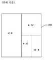
도 2는 종래의 CAN 라우팅 전략을 나타내는 도면.2 illustrates a conventional CAN routing strategy.
도 3은 종래의 CHORD 라우팅 전략을 나타내는 도면.3 shows a conventional CHORD routing strategy.
도 4는 로컬 머신 환경의 컨텍스트에서 데이터 구조의 두 객체를 링크하기 위한 종래기술을 나타내는 도면.4 illustrates a prior art for linking two objects of a data structure in the context of a local machine environment.
도 5는 P2P 분산 해시 테이블(DHT) 환경에서 데이터 구조의 두 객체를 링크하기 위한 예시기술을 나타내는 도면으로서, 두 객체는 P2P DHT 환경의 두개의 상이한 노드와 관련되고, 링크 기술은 DHT의 "상부"에 배치된 데이터 오버레이의 기본을 형성한다.FIG. 5 illustrates an example technique for linking two objects of a data structure in a P2P Distributed Hash Table (DHT) environment, where the two objects are associated with two different nodes of the P2P DHT environment, and the link technique is the "top" of the DHT. Form the basis of the data overlay placed on.
도 6은 링, 존, 및 각 사이드에 r 개의 이웃을 기록하는 기본 라우팅 테이블을 포함하는 단순한 P2P DHT를 나타내는 도면으로서, 해싱은 DHT 노드에 존을 할당한다.Figure 6 shows a simple P2P DHT that includes a ring, zone, and a basic routing table that records r neighbors on each side, with hashing assigning zones to the DHT nodes.
도 7은 도 5에 도시된 데이터 오버레이의 개념을 사용하여 구축된 예시적인 트리 구조를 나타내는 도면으로서, 트리 구조는 자가-조직 메타데이터 오버레이 (SOMO)라고 한다.FIG. 7 is a diagram illustrating an exemplary tree structure built using the concept of data overlay shown in FIG. 5, which is called a self-organization metadata overlay (SOMO).
도 8a 내지 8c는 상향식으로 SOMO를 구축하기 위한 프로세스의 순차적인 개략 도면으로서, 도 8a는 기준 프레임으로서 논리 트리를 구축하는 것을 나타내는 도면이고, 도 8b는 대표적인 가상 노드를 조사하는 것을 나타내는 도면이고, 도 8c는 물리적 머신으로 논리 트리를 매핑하는 것을 나타내는 도면이다.8A through 8C are sequential schematic diagrams of a process for constructing SOMO from the bottom up, FIG. 8A illustrates building a logical tree as a reference frame, and FIG. 8B illustrates examining a representative virtual node. 8C is a diagram illustrating mapping a logical tree to a physical machine.
도 9a 내지 9c는 도 8c에 도시된 상향식 SOMO를 치유하기 위한 자가-조정 프로세스의 순차적인 개략 도면으로서, 도 9a는 도 8c에 도시된 상향식 SOMO를 나타내는 도면이고, 도 9b는 물리적 머신을 추가하는 것을 나타내는 도면이고(대응하는 대표적인 가상 노드가 물리적 머신을 위한 논리 트리에서 발견됨), 도 9c는 모든 물리적 머신으로 교정된 논리 트리를 매핑하는 것을 나타내는 도면이다.9A-9C are sequential schematic diagrams of the self-tuning process for healing the bottom-up SOMO shown in FIG. 8C, FIG. 9A showing the bottom-up SOMO shown in FIG. 8C, and FIG. 9B illustrates the addition of a physical machine. (The corresponding representative virtual node is found in the logical tree for the physical machine), and FIG. 9C is a diagram illustrating the mapping of the corrected logical tree to all physical machines.
도 10a는 집합적으로 자원 풀을 만들기 위한 자원 풀링 및 상향식 SOMO에 대한 DHT의 성능의 결합을 나타내는 도면.FIG. 10A illustrates the combination of performance of DHT for resource pooling and bottom-up SOMO to collectively create resource pools. FIG.
도 10b는 P2P 시스템의 참가자로부터의 정보의 수집 및 P2P 시스템의 참가자로의 정보의 유포에 대한 도 7의 SOMO 트리 구조의 예시적인 애플리케이션을 나타내는 도면.FIG. 10B illustrates an exemplary application of the SOMO tree structure of FIG. 7 for the collection of information from participants in a P2P system and the dissemination of information to participants in a P2P system.
도 11a는 애플리케이션 레벨 멀티캐스팅을 위한 개략적인 구성을 나타내는 도면이고, 도 11b는 자원 풀의 헬퍼 노드를 사용함으로써 도 11a에 도시된 구성이 향상되는 것을 나타내는 도면이다. 여기서, 원은 애플리케이션 레벨 멀티캐스팅 세션의 원래의 구성원을 나타내고, 사각형은 큰 차수를 갖는 사용가능한 피어를 나타낸다.FIG. 11A illustrates a schematic configuration for application level multicasting, and FIG. 11B illustrates that the configuration illustrated in FIG. 11A is improved by using a helper node of a resource pool. Here, the circles represent original members of the application level multicasting session, and the squares represent available peers of large order.
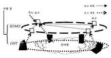
도 12는 단일의 애플리케이션 레벨 멀티캐스팅 세션을 스케줄링하기 위한 SOMO 보고 구조를 나타내는 도면으로서, 각 노드는 SOMO에게 그들의 보고 내의 대역폭 제한 뿐만 아니라 그들의 네트워크 좌표를 알린다.12 illustrates an SOMO reporting structure for scheduling a single application level multicasting session, in which each node informs the SOMO of their network coordinates as well as the bandwidth limitations in their report.
도 13은 P2P 시스템의 참가자를 구현하는 데에 사용되는 예시적인 컴퓨터를 나타내는 도면으로서, P2P 시스템은 그 DHT의 상부에 구축된 데이터 오버레이를 포함한다.FIG. 13 illustrates an example computer used to implement a participant of a P2P system, wherein the P2P system includes a data overlay built on top of its DHT.
본 발명은 피어-투-피어(peer-to-peer) 시스템과 상호작용하는 데이터 구조를 이용하고, 또 애플리케이션 레벨의 멀티캐스팅(application level multicasting, ALM)을 갖는 기술을 사용하기 위한 기술 및 분산 데이터 구조(distributed data structure)에 관련되어 있다.The present invention utilizes data structures that interact with peer-to-peer systems, and also uses techniques and distributed data to use techniques with application level multicasting (ALM). It is related to a distributed data structure.
피어-투-피어(P2P) 시스템은, 동일하거나 유사한 능력 및 책임을 갖는 참가 머신을 연결하는 네트워크를 사용한다. 이러한 시스템은 종래의 서버에 의한 조정없이(또는 서버에 의한 최소의 설정 조정으로) 작업을 수행한다. 예를 들면, 도 1은 P2P 시스템(100)에 대한 상위 수준의 묘사를 도시한다. 시스템(100)은 동일하거나 유사한 능력 및 책임을 갖는 피어 엔티티(102-112)의 집합을 포함한다. 일 예시에서, 피어 엔티티(102-110)는 인터넷 또는 인트라넷을 통해 함께 연결된 독립된 개인용 컴퓨터 장치에 해당할 수 있다. 피어 엔티티(102-110)는 그들 간에(예 시 통신 경로 114로써 지시되는 대로) 파일 또는 다른 정보를 서버의 도움없이 직접 전송할 수 있다. P2P 시스템에 대한 일반적인 소개는, 2002년 HP Lab에서 D. S. Milojicic, V. Kalogeraki, R. Lukose, K. Nagaraja, J. Pruyne, B. Richard, S. Rollins, 및 Z. Xu.가 발표한 기술보고서 제 HPL-2002-57호의 "Peer-To-Peer Computing" 에서 찾을 수 있다.Peer-to-peer (P2P) systems use networks that connect participating machines with the same or similar capabilities and responsibilities. Such a system performs work without adjustments by conventional servers (or with minimal setting adjustments by servers). For example, FIG. 1 shows a high level depiction of a
P2P 시스템은 시스템 내에서 참가 피어 엔티티로부터 객체의 저장 및 추출을 용이하게 하기 위해서 일반적으로 분산 해시 테이블(ditributed hash table, DHT)을 사용한다. 이름이 암시하는 바대로, 분산 해시 테이블(DHT)은, 별개의 컴퓨터 장치에 연결된 복수의 저장소에 걸쳐 분산된 것과 같이 복수의 장소에 걸쳐 분산되어 있는 해시 테이블을 지칭한다. 분산 해시 테이블은 개별적으로 할당된 ID를 갖는 복수의 DHT 노드를 지정한다. DHT 노드는 추상 DHT 논리 공간(abstract DHT logical space)을 집합적으로 정의한다. 키를 생산하는 해시 함수(hashing function)에 객체를 위임함으로써, 객체는 DHT 논리 공간으로 삽입되거나, DHT 논리공간으로부터 추출될 수 있다. 다음, 이 키는 객체를 수용하거나, 그로부터 객체가 추출될 수 있는 DHT 논리 공간에서 특정 목표 노드 ID의 위치를 찾는데 사용된다. 즉, 각 DHT 노드는 키의 어떤범위와 연관되어 있다; 객체는 그 객체의 키가 특정 DHT 노드와 연관된 키의 범위 내로 떨어지는지 여하에 따라 그 특정 DHT 노드에 추가되거나, 그로부터 추출될 수 있다. 비-분산 해시 테이블 구현과는 다르게, DHT 노드는 자유롭게 DHT 논리 공간에 합류하고, DHT 논리 공간을 떠날 수 있어서(예컨대, P2P 시스템에 합류 및 시스템을 떠나는 컴퓨터 장치에 각각 해당함), 이러 한 사건을 이끌어 내기 위해서는 기능성이 제공되어야 한다P2P systems generally use a distributed hash table (DHT) to facilitate the storage and extraction of objects from participating peer entities in the system. As the name suggests, a distributed hash table (DHT) refers to a hash table that is distributed across a plurality of locations, such as across a plurality of repositories connected to separate computer devices. The distributed hash table specifies a plurality of DHT nodes with individually assigned IDs. The DHT node collectively defines an abstract DHT logical space. By delegating the object to a hashing function that produces a key, the object can be inserted into or extracted from the DHT logical space. This key is then used to accept the object or to locate the specific target node ID in the DHT logical space from which the object can be extracted. That is, each DHT node is associated with a certain range of keys; An object may be added to or extracted from that particular DHT node depending on whether the object's key falls within the range of keys associated with that particular DHT node. Unlike non-distributed hash table implementations, DHT nodes can freely join DHT logical spaces and leave DHT logical spaces (e.g., corresponding to computer devices joining and leaving the P2P system, respectively). Functionality must be provided to elicit
P2P 시스템에서 객체의 저장 및 추출을 관리하기 위해서 다양한 종류의 DHT 전략이 개발되어 왔다. 도 2는 콘텐츠 어드레서블 네트워크(Content Addressable Network(CAN)) 전략을 도시하는데, 예를 들면, 2001년 8월 미국 캘리포니아주 샌디에고에서 열린 ACM SigComm 2001에서 S. Ratnasamy, P. Francis, M. Handley, R. Karp, 및 S. Shenker가 발표한, "Scalable Content-Addressable Network"에 기술된 내용을 들 수 있다. 이 전략은, D-차수 직교 공간(D-dimensional Cartesian space)(200)으로서 DHT 논리 공간을 모델링한다. 노드가 DHT 공간(200)에 합류할 때, CAN 전략은 공간(200)을 분할한다. 예를 들면, 노드(n1)가 합류할 때, CAN 전략은 전체 공간(200)을 이 노드로 할당한다. 노드(n2)가 합류할 때, CAN 전략은 공간(200)을 두 개의 반(two halves)으로 나눈 후, 각 반을 노드(n1) 및 노드(n2)에 각각 할당한다. 노드(n3)가 합류할 때, CAN 전략은 우반(the right half)을 상부 4분의 1(upper quarter) 및 하부 4분의 1(lower quarter)로 나누고, 상부 4분의 1을 노드 n2에 하부 4분의 1을 노드(n3)에 할당한다. 그리고, 노드(n4)가 합류할 때, CAN 전략은 하부 우 4분의 1을 좌 8분의 1(노드(n3)에 할당됨) 및 우 8분의 1(노드(n4)에 할당됨)로 나눈다. 이 절차는 추가 및 제거되고 있는 노드를 설명하기 위한 필요에 따라 얼마든지 반복될 수 있다. 결과로 나타난 분할부는, 분산 해시 테이블 내로 및 그로부터 객체를 삽입 및 추출하는데 사용되는 논리 공간의 경계를 정한다. 노드는 그의 공간에 위치하는 객체를 "소유"한다고 언급될 수 있다.Various types of DHT strategies have been developed to manage the storage and extraction of objects in P2P systems. FIG. 2 illustrates a Content Addressable Network (CAN) strategy, for example S. Ratnasamy, P. Francis, M. Handley at ACM SigComm 2001 in San Diego, California, USA, August 2001. , "Scalable Content-Addressable Network" published by R. Karp, and S. Shenker. This strategy models the DHT logical space as a D-dimensional Cartesian
도 3은 CHORD(예컨대, 2001년 8월 미국 캘래포니아주 샌디에고서 열린 ACM SigComm 2001에서 I. Stoica, R. Morris, D. Karger, M.F. Kaashoek, 및 H. Balakrishnan이 발표한, "Chord: a Scalable Peer-To-Peer Lookup Service for Internet Applications"에 기술되어 있는)로 지칭되는 또 다른 전략을 도시한다. 이 전략에서, DHT 논리 공간은 원형 공간(300)으로 구조화되어 있다. DHT 노드는 ID를 할당받은 후, 그 할당된 ID에 기초하여 원형 DHT 논리 공간(300)에 추가된다. 예를 들면, 도 3에 도시된 예시 DHT 노드(n1, n2, n3, n4 및 n5)는 원형 DHT 논리 공간(300) 상에 그들의 "위치"를 지배하는 할당된 ID를 갖는다. 도 2의 경우와 마찬가지로, DHT 노드는 그들이 추가될 때, DHT 논리 공간(300)을 분할하며, 복수의 부분공간(subspace) 또는 존(zone)의 경계가 정해진다. 이러한 존은 각 노드가 "소유"하는 객체를 정의한다. 예를 들면, 도 3에 도시된 DHT 전략에 의해 지배되는 분산 해시 테이블로 객체를 삽입하기 위해서, 객체는 키를 생산하는 해시 함수로 위임된다. 다음, 객체는 그 키가 할당된 존을 포함하는 DHT 노드(예컨대, 그 객체의 키를 포함하는 어떤 키의 범위를 둘러싸는 DHT 노드)에 저장된다. 도 2및 도 3 두 경우 모두에 있어서, P2P 시스템 내 특정 노드를 빠르게 찾기 위해서 다양한 룩업(lookup) 전략이 사용될 수 있다. 일반적으로, 룩업 전략은 요구되는 목표 DHT 노드 상에서 좁히기 위해 DHT 논리 공간에서 수 개의 "홉(hop)"을 만드는 것을 포함한다. 이러한 탐색 속도를 촉진시키기 위하여 일반적으로 다양한 메커니즘이 제공된다. 예를 들면, CHORD 전략에서 각 DHT 노드는 다른 DHT 노드 집합의 ID를 저장한다. 이러한 다른 ID는 논리 공간(300) 속을 정밀 검사하는 소위 "핑거(finger)"를 설정하면서 지수적으로 증가할 수 있다. 이것은 룩업 절차가 요 구되는 DHT 노드의 위치를 작은 개수의 홉으로써 빨리 찾게 한다.FIG. 3 shows CHORD (eg, “Chord: a Scalable,” published by I. Stoica, R. Morris, D. Karger, MF Kaashoek, and H. Balakrishnan at ACM SigComm 2001 held in San Diego, CA, August 2001). Peer-To-Peer Lookup Service for Internet Applications. In this strategy, the DHT logical space is structured into a
도 2 및 3은 두 개의 공지된 예시 DHT 라우팅 전략에 대해 단지 상위 수준의 개요를 제공한다. 다른 전략이 많이 있다. 예를 들면, 인기 있는 라우팅 전략의 또 다른 하나로, 2001년 11월 독일 하이델베르그에서 열린 제 18회 FIFP/ACM International Conference on Distributed Systems Platforms (Middleware)에서 A. Rowstron과 P. Druschel이 발표한, "Pastry: Scalable, Distributed Object Location and Routing for Large-Scale Peer-To-Peer Systems"에 기술된 PASTRY 라우팅 전략을 들 수 있다.2 and 3 provide only a high level overview of two known example DHT routing strategies. There are many other strategies. For example, as another popular routing strategy, A. Rowstron and P. Druschel at the 18th FIFP / ACM International Conference on Distributed Systems Platforms (Middleware) in Heidelberg, Germany, in November 2001, "Pastry The PASTRY routing strategy described in “Scalable, Distributed Object Location and Routing for Large-Scale Peer-To-Peer Systems”.
P2P 시스템은 종래의 클라이언트-서버 전략에 비해 많은 혜택을 제공한다. 예를 들면, P2P 시스템은 중앙의 조정없이 자동적으로 자유롭게 확장 및 축소할 수 있는 능력이 있다. 그러나, 이렇게 관리 조정이 부족한 점은 또한, 다양한 도전을 야기한다. 예를 들면, 어떤 글로벌 기능을 수행하기 위해서 P2P 시스템이 일제히 동작하게 하는 것이 바람직할 수 있다. 다양한 경우에 있어서, P2P 시스템의 참가자로부터 데이터를 수집하는 것이 바람직할 수 있다. 또는, P2P 시스템에 있는 참가자들에게 정보를 유포하는 것이 바람직할 수 있다. 클라이언트-서버 접근 방식에서는, 서버는 그 클라이언트로부터 정보를 취합하도록 하기 위해서 단순히 그의 클라이언트에게 폴링하거나, 그 클라이언트에게 정보를 유포하기 위해서 그의 클라이언트에게 정보를 방송할 수 있다. 그러나, 데이터 수집 및 유포는 P2P 시스템에서는 좀 더 문제가 되는데, 왜냐하면 P2P 시스템은 상호연결된 피어가 자유롭게 오고 갈 수 있도록 느슨한 연합에 의해 형성되어 있기 때문이다. 종래의 중앙형 보 고 기능(reporting functionality)을 추가하는 것은, P2P 시스템을 복잡하게 하여 그 융통성이나 이용성을 축소하는 결과가 된다.P2P systems provide many benefits over conventional client-server strategies. For example, P2P systems have the ability to automatically expand and contract freely without central adjustment. However, this lack of management coordination also poses a variety of challenges. For example, it may be desirable to have P2P systems work in unison to perform certain global functions. In various cases, it may be desirable to collect data from participants in a P2P system. Or, it may be desirable to disseminate information to participants in the P2P system. In a client-server approach, a server can simply poll his client to collect information from that client, or broadcast the information to his client to disseminate the information to that client. However, data collection and dissemination are more problematic in P2P systems, because P2P systems are formed by loose associations that allow interconnected peers to come and go freely. Adding the traditional centralized reporting functionality complicates the P2P system, resulting in reduced flexibility and usability.
따라서, P2P DHT와 상호작용하기 위한 효율적인 전략 분야에서는, 예를 들면, 그 참가자로부터 데이터를 취합하고 그 참가자에게 정보를 유포하는 것이 가능하도록 하는 예시적인 요구가 있다. 나아가, 효율적으로 P2P DHT를 편성하고, 애플리케이션 레벨의 멀티캐스팅 동작에서와 같이, 그 효율성으로부터 혜택을 얻을 동작에서 P2P DHT와 상호작용하는 것이 요구될 수 있다.Thus, in the field of efficient strategies for interacting with P2P DHT, there is an exemplary need to make it possible to collect data from, and to disseminate information to, for example. Furthermore, it may be desired to efficiently organize P2P DHT and interact with the P2P DHT in an operation that would benefit from that efficiency, such as in an application level multicasting operation.
일 예시 구현에 따르면, 데이터 오버레이를 구축하기 위한 방법이 기술된다. 상기 방법은 피어-투-피어 시스템 속으로 및 시스템으로부터 객체를 삽입하고 추출하는 것을 지배하는 분산 해시 테이블(DTH)의 제공을 포함하는데, 여기에서 분산 해시 테이블은, 관련된 복수의 DHT 존을 포함하는 DHT 노드를 복수 포함하는 논리 공간을 포함한다. 상기 방법은 또한, 데이터 구조 내에 있는 객체를 DHT 노드에 연관시킴으로써 또, 데이터 구조 내에 있는 객체들 간 링크를 설정시킴으로써 분산 해시 테이블의 논리 공간 상부에 데이터 구조로서 데이터 오버레이를 구축하는 것을 포함한다. 데이터 오버레이는 트리 토폴로지를 갖는데, 트리는 개별적인 DHT 노드와 연관된 트리 노드를 갖는다. 각 트리 노드는, 분산 해시 테이블에 대한 논리 공간의 일부에 해당하는 것과 연관된 개별적인 트리 노드 존을 갖는다.According to one example implementation, a method for building a data overlay is described. The method includes providing a distributed hash table (DTH) that governs inserting and extracting objects into and out of a peer-to-peer system, wherein the distributed hash table includes a plurality of associated DHT zones. It includes a logical space including a plurality of DHT nodes. The method also includes establishing a data overlay as a data structure on top of the logical space of the distributed hash table by associating an object in the data structure to the DHT node and establishing a link between the objects in the data structure. The data overlay has a tree topology where the tree has tree nodes associated with individual DHT nodes. Each tree node has a separate tree node zone associated with that portion of the logical space for the distributed hash table.
머신은 DHT의 논리 공간으로 매핑된다(mapped). 각 머신은 하나 이상의 트리 토드 존에 해당한다. 각 머신은, 그 머신에 해당하는 하나 이상의 트리 노드 존으로부터 가장 큰 크기의 트리 노드 존을 그의 대표 노드(representative node)로서 선택한다. 각 대표 노드는, 그의 부모 노드로서 더 큰 크기를 갖는 이웃 트리 노드 존에 대한 대표 노드인 또 다른 대표 노드를 선택한다.The machine is mapped to the logical space of the DHT. Each machine corresponds to one or more tree Todd zones. Each machine selects as its representative node the tree node zone of the largest size from one or more tree node zones corresponding to that machine. Each representative node selects, as its parent node, another representative node that is a representative node for the neighboring tree node zone having a larger size.
머신이 DHT의 논리 공간으로 매핑된 이후, 메타데이터는 각 머신에서 메타데이터를 취합할 수 있다. 취합된 메타데이터는 각 머신으로부터 그의 대표 노드로 송신될 수 있고, 그러한 대표 노드는, 그렇게 수신된 메타데이터를 그들의 개별적인 부모 노드로 송신할 수 있다. 트리에서 가장 높은 노드에 수신된 메타데이터(예컨대, 루트 노드)는 처리된 후, 개별적인 부모 및 대표 노드를 통해서 각 머신으로 송신될 수 있다. 메타데이터는 예를 들면, 각 머신의 동작에 관한 정보일 수 있으며, 처리된 메타데이터는 각 머신의 동작을 지배할 수 있는 명령어일 수 있다.After the machines are mapped into the logical space of the DHT, the metadata can collect the metadata on each machine. Aggregated metadata can be sent from each machine to its representative node, and such representative node can send the received metadata to their respective parent node. Metadata (eg, root node) received at the highest node in the tree can be processed and sent to each machine through separate parent and representative nodes. The metadata may be, for example, information about the operation of each machine, and the processed metadata may be instructions that can govern the operation of each machine.
추가적인 구현 및 특징(feature)들은 이하에서 기술될 것이다.Additional implementations and features will be described below.
다음의 첨부 도면과 같이 후술하는 상세한 설명을 참조함으로써, 본 발명의 구현이 더 잘 이해될 수 있다.The implementation of the present invention may be better understood by reference to the following detailed description, as follows in the accompanying drawings.
본 명세서외 도면에서 유사한 구성요소와 특징을 나타내는 데에 동일한 번호가 사용된다. 100 번호 시리즈는 원래 도 1에 도시된 특징을, 200 번호 시리즈는 원래 도 2에 도시된 특징을, 300 번호 시리즈는 원래 도 3에 도시된 특징을 나타내고, 나머지도 마찬가지이다.Like numbers are used to designate like elements and features in the figures. The 100 number series originally represented the features shown in FIG. 1, the 200 number series originally indicated the features shown in FIG. 2, and the 300 number series originally indicated the features shown in FIG. 3, and so on.
본 명세서에서 설명되는 전략은 피어-투-피어(P2P) 시스템에서 사용되는 분산 해시 테이블(DHT)의 "상부(on top of)"에 구축된 데이터 구조를 포함한다. 피 어-투-피어(P2P) 시스템이라는 용어는 도 1에 도시된 상호연결 네트워크(100)와 같이, 참가자가 직접적으로 다른 참가자와 상호작용할 수 있는, 참가자에 대한 임의의 상호연결을 설명할 수 있다. 일 실시예에서, P2P 시스템은 임의의 서버형 엔티티의 지원을 필요로 하지 않는다. 참가자는 개인용 컴퓨터, 랩탑 컴퓨터, PDA, 주문형 컴퓨팅 장치 등을 포함하는, 임의의 종류의 엔티티를 포함할 수 있다. 참가자는 고정배선 및/또는 무선 통신 라우팅 메카니즘, 다양한 라우터, 게이트웨이 등과 같이, 라우팅 인프라의 임의의 조합을 통하여 서로 통신할 수 있다. 또한, 참가자는 TCP/IP(예를 들어, 인터넷 또는 인트라넷에 의해 제공되는)와 같은 네트워크 프로토콜의 임의의 조합을 통하여 서로 통신할 수 있다.The strategy described herein includes a data structure built on top of a distributed hash table (DHT) used in a peer-to-peer (P2P) system. The term peer-to-peer (P2P) system may describe any interconnection to a participant, in which the participant can directly interact with another participant, such as the
더 일반적으로, 본 명세서에서 설명되는 임의의 기능은 소프트웨어, 펌웨어(예를 들어, 고정 논리 회로), 매뉴얼 프로세싱, 또는 이러한 구현의 조합을 사용하여 구현될 수 있다. 본 명세서에서 일반적으로 사용되는 "논리" 또는 "모듈"이라는 용어는 소프트웨어, 펌웨어, 또는 소프트웨어 및 펌웨어의 조합을 나타낸다. 예를 들어, 소프트웨어 구현의 경우에, "논리" 또는 "모듈"이라는 용어는 프로세싱 장치 또는 장치들(예를 들어, CPU 또는 CPU들) 상에서 작동될 때 특정 작업을 수행하는 프로그램 코드를 나타낸다. 프로그램 코드는 하나 이상의 컴퓨터 판독가능 메모리 장치에 저장될 수 있다.More generally, any of the functions described herein may be implemented using software, firmware (eg, fixed logic circuits), manual processing, or a combination of these implementations. The term "logical" or "module" as used generally herein refers to software, firmware, or a combination of software and firmware. For example, in the case of a software implementation, the term "logical" or "module" refers to program code that performs certain tasks when run on a processing device or devices (eg, a CPU or CPUs). The program code may be stored in one or more computer readable memory devices.
본 명세서는 다음의 내용을 포함한다: 섹션 A는 P2P DHT의 "상부"에 구축될 수 있는 일반적인 데이터 오버레이 구조를 기술한다; 섹션 B는 자가-조직 메타데이터 오버레이(Self-Organized Metadata Overlay), 또는 "SOMO"를 기술한다; 섹션 C 는 P2P 시스템에서 정보의 취합 및 유포를 위한 SOMO의 적용을 기술한다; 섹션 D는 P2P DHT를 사용하여 애플리케이션 레벨 멀티캐스팅(Application Level Multicasting; ALM)을 기술한다; 섹션 E는 섹션 A-D에서 기술된 바와 같은 ALM을 갖는 P2P DHT 시스템 유형에서 사용될 수 있는 예시적인 P2P 참가자를 이용하는 것을 기술한다.This specification includes the following: Section A describes a general data overlay structure that may be built on top of a P2P DHT; Section B describes a Self-Organized Metadata Overlay, or “SOMO”; Section C describes the application of SOMO for the collection and dissemination of information in P2P systems; Section D describes Application Level Multicasting (ALM) using P2P DHT; Section E describes using an example P2P participant that can be used in a P2P DHT system type with ALM as described in sections A-D.
A. P2P DHT 상의 데이터 오버레이A. Data Overlays on P2P DHT
데이터 오버레이는 객체들로 구성되는 데이터 구조이다. 데이터 구조는 분산 해시 테이블의 "상부"에 구현된다. 백그라운드로서, DHT는 P2P 시스템에 의해 제공되는 분산 저장소로 객체를 삽입 및 그로부터 객체를 추출하기 위한 기술을 제공한다. DHT는 논리 DHT 공간 내의 DHT 노드의 집합을 정의함으로써 이러한 작업을 수행한다. 즉, DHT 기술은 DHT 노드의 "존(zone)"이라고 하는, DHT 논리 공간의 소정의 부분에 각 DHT 노드를 할당한다. 예를 들어, CHORD 기술에서, 특정 DHT 노드의 존은 원형 DHT 논리 공간(예를 들어 도 3에 도시된 바와 같은)의 특정 DHT 노드와 그 근처의 노드 사이에서 정의되는 스팬(span)으로 해석될 수 있다. 객체는 키를 생성하기 위하여 객체를 해싱함으로서 저장되고, 그 후 이러한 키를 사용하여 객체와 DHT 논리 공간의 특정 노드 ID를 관련시킨다. 객체는 연관된 방식으로 DHT 논리 공간으로부터 추출된다. 노드와 머신 사이에 일대일 관계가 필요하지 않다고 하여도, 결국 관련된 존들은 실제 머신(예를 들어, 컴퓨터 장치 및 관련 파일 저장소 시스템)으로 매핑한다.A data overlay is a data structure composed of objects. The data structure is implemented at the "top" of the distributed hash table. As a background, DHT provides a technique for inserting objects into and extracting objects from distributed storage provided by a P2P system. The DHT accomplishes this by defining a set of DHT nodes in the logical DHT space. In other words, the DHT technology assigns each DHT node to a predetermined portion of the DHT logical space, called the "zone" of the DHT node. For example, in the CHORD technique, the zone of a particular DHT node is to be interpreted as a span defined between a particular DHT node in a circular DHT logical space (eg, as shown in FIG. 3) and a node near it. Can be. The object is stored by hashing the object to generate a key, which is then used to associate the object with a particular node ID in the DHT logical space. Objects are extracted from the DHT logical space in an associated manner. Even if a one-to-one relationship is not required between the node and the machine, eventually the associated zones map to a real machine (eg, a computer device and associated file storage system).
데이터 오버레이는 그 객체들이 DHT 논리 공간에서 노드들과 관련된다는 의 미에서 DHT의 "상부"에서 구현된다. 또한, 애플리케이션은 P2P DHT의 기초 프로토콜 및 서비스를 사용하여 데이터 오버레이의 데이터 구조에서 하나의 객체로부터 다른 객체로 횡단(traverse)한다(또는, 경로를 정한다). 더 구체적으로, 기준 프레임을 위하여, 단일 머신 환경(402)에 대한 도 4의 종래의 경우를 고려한다. 이러한 환경(402)에서, 데이터 구조는 두개의 객체, a(404) 및 b(406)를 포함하며, 단일 머신에 의해 제공되는 저장 장치에서 구현된다. 객체는 임의의 형태의 정보의 임의의 유닛을 폭넓게 나타낸다; 종래의 경우에, 예를 들어, 객체는 데이터베이스 기록, 예를 들어, 문서에 해당할 수 있다. 도 4의 예에서, 객체 a(404)는 객체 b(406)를 참조하는 포인터(408)를 포함한다.Data overlay is implemented at the "top" of the DHT, meaning that the objects are associated with nodes in the DHT logical space. In addition, the application traverses (or routes) from one object to another object in the data overlay's data structure using the underlying protocols and services of P2P DHT. More specifically, for the reference frame, consider the conventional case of FIG. 4 for a single machine environment 402. In such an environment 402, the data structure includes two objects, a 404 and
반면에, 도 5는 P2P DHT 환경(502)의 컨텍스트에서 데이터 오버레이의 구현을 나타낸다. 이러한 환경(502)에서, 객체들은 DHT에 의해 이미 제공되는 DHT 노드 프레임워크의 "상부"에 구축되기 때문에, DHT 논리 공간의 개개의 노드들은 데이터 오버레이의 객체들을 "호스트(host)"한다. 예를 들어, DHT 노드 x(504)는 객체 a(506)를 호스트하고, DHT 노드 y(508)는 객체 b(510)를 호스트한다. 이러한 예에서, 객체 a(506)는 객체 b(510)를 참조한다. 일반적으로, 객체 b(510)에 액세스하는 데에 사용되는 키를 저장함으로써, 객체 a(506)는 객체 b(510)로 링크할 수 있다. 이러한 키는 객체 b(510)가 생성될 때 설정된다. 그러나, 도 5의 경우에, 참조 방식(referencing scheme)은 두개의 필드를 포함한다. 제1 필드(512)는 객체 a(506)로부터 객체 b(510)로 포인트하는 고정배선 주소를 포함한다. 이러한 필드는 a.foo.key라고 한다. 제2 필드(514)는 객체 b(510)를 호스트하는 마지막으로 알려진 DHT 노드(예를 들어, 노드 y(508))를 식별하는 소프트-상태 참조(soft-state reference)를 포함한다. 이러한 필드는 a.foo.host라고 한다. 따라서, 제2 필드(514)는 객체 b(510)에 엑세스하기 위한 라우팅 지름길의 역할을 한다.In contrast, FIG. 5 shows an implementation of a data overlay in the context of a
데이터 오버레이의 노드들은 복수의 DHT 노드들 상에서 분산되기 때문에, 데이터 오버레이 그자체가 분산 데이터 구조로 간주될 수 있다. 데이터 구조가 분산된다고 하더라도, 그 객체들이 과도하지 않으면서 지리적으로 넓게 분산되는 방식으로 저장하는 것이 바람직할 수 있다. 이는 그들이 서로 가까이 있도록 a(506) 및 b(510)의 키들을 생성함으로써 얻어질 수 있다. 이는 P2P DHT 시스템이 이러한 키들을 P2P 시스템의 동일한 노드 또는 P2P DHT 시스템의 아주 가깝게 연관된 노드들과 관련되도록 할 가능성을 더 높여준다.Since the nodes of the data overlay are distributed over a plurality of DHT nodes, the data overlay itself can be considered a distributed data structure. Even if the data structure is distributed, it may be desirable to store the objects in a geographically widely distributed manner without being excessive. This can be obtained by generating the keys of a 506 and
또한, 데이터 오버레이는 그 데이터 구조의 포인터 및 객체를 조작하는 데에 사용되는 프리미티브(primitive)의 집합을 제공한다. 더 구체적으로, 이러한 프리미티브는 객체 a로부터 다른 객체 b로 참조를 설정하기 위한 절차(setref), 객체 a에 의하여 포인트되는 객체를 반환시키기 위한 절차(deref), 및 객체 a에 의하여 포인트되는 객체를 삭제하기 위한 절차(delete)를 포함한다.In addition, a data overlay provides a set of primitives used to manipulate pointers and objects of that data structure. More specifically, these primitives may include a procedure for setting a reference from object a to another object b, a procedure for returning an object pointed to by object a, and an object pointed to by object a. It includes a procedure to delete.
데이터 오버레이는 DHT 시스템의 상부에 구현되기 때문에, 그 프리미티브는 DHT의 서비스를 사용한다. 예를 들어, 프리미티브는 DHT 논리 공간에 객체를 삽입하기 위한 DHT_insert 서비스를 사용할 수 있다. 프리미티브는 DHT 논리 공간에서 그 키를 기초로 하는 객체를 찾는 소정의 DHT 라우팅 절차(DHT routing procedure)를 사용하기 위한 DHT_lookup 서비스(CHORD에 의해 사용되는 지수적 핑거 룩업 구 조와 같은)를 사용할 수 있다. 또한, 프리미티브는 객체를 저장하는 DHT 노드가 미리 알려진 경우에 객체에 직접 액세스하기 위한 DHT_direct 절차를 사용할 수 있다. 달리 말하자면, 그 키가 주어지면 DHT_direct는 정규의 DHT_lookup 라우팅 절차를 바이패스(bypass)하고, 객체를 호스트하는 노드를 직접 구한다. 부차적으로, DHT_lookup 및 DHT_insert는 모두 현재 목표 객체를 호스트하는 DHT의 DHT 노드를 복귀시킬 것이다.Since the data overlay is implemented on top of the DHT system, its primitives use the services of the DHT. For example, primitives can use the DHT_insert service to insert objects into the DHT logical space. Primitives can use the DHT_lookup service (such as the exponential finger lookup structure used by CHORD) to use a given DHT routing procedure to find an object based on that key in the DHT logical space. In addition, the primitive may use the DHT_direct procedure for directly accessing the object when the DHT node storing the object is known in advance. In other words, given that key, DHT_direct bypasses the regular DHT_lookup routing procedure and directly retrieves the node hosting the object. Incidentally, both DHT_lookup and DHT_insert will return the DHT node of the DHT that currently hosts the target object.
데이터 오버레이는 객체를 생성하기 위하여 어떠한 라이브러리 루틴이 사용되더라도 이를 수정함으로써 그 기초 DHT 서비스를 이용하여 구현될 수 있는데, 또한 이러한 루틴은 객체의 속성으로서 상술한 바 있는 포인터를 설정하기 위한 것이다. 또한, 라이브러리 루틴은 참조를 설정하고, 참조에 의해 포인트된 객체를 복귀시키고, 및 참조에 의해 포인트된 객체를 삭제하기 위한 상술한 바 있는 프리미티브를 조정하도록 수정되어야만 한다.The data overlay can be implemented using the underlying DHT service by modifying whatever library routine is used to create the object, which is also for setting the pointer as described above as an attribute of the object. In addition, the library routines must be modified to adjust the primitives described above for setting the reference, returning the object pointed by the reference, and deleting the object pointed to by the reference.
DHT의 상부에 데이터 오버레이를 구축하는 것에는 많은 이점이 있다. 예컨대, DHT는 DHT 노드들이 DHT 논리 공간에 추가되거나 그로부터 삭제될 때(이는 각각 P2P 시스템에 합류하거나 P2P 시스템을 떠날 때와 관련됨) 자가-조직되도록 디자인되어 있다. DHT는 또한 DHT 노드들이 DHT 논리 공간에 추가되거나 그로부터 삭제되는 것에 대한 응답으로 (노드들 간의 링크를 재설정하고, 노드들간의 객체들을 전송하는 것 등에 의해) 자동적으로 스스로 "치유(healing)"하도록 디자인되어 있다. 데이터 오버레이가 DHT의 상부에서 구현되는 것에 힘입어, 데이터 오버레이는 또한, 자가-조직 및 자가-치유(self-healing)의 특징들을 채택할 수 있다. 더 구체적으로, 데이터 오버레이는 기초 DHT(underlying DHT)와 동일한 크기로 자가-조직 및 자가-치유 되도록 구성될 수 있다.There are many advantages to building a data overlay on top of the DHT. For example, DHT is designed to self-organize when DHT nodes are added to or removed from the DHT logical space (which is associated with each joining or leaving a P2P system, respectively). DHT is also designed to automatically "healing" itself (such as by resetting links between nodes, transferring objects between nodes, etc.) in response to DHT nodes being added to or removed from the DHT logical space. It is. Thanks to the data overlay being implemented on top of the DHT, the data overlay can also adopt the features of self-organization and self-healing. More specifically, the data overlay can be configured to self-tissue and self-heale to the same size as the underlying DHT.
또한, 실행하기 위하여 P2P DHT의 상부에 다양한 애플리케이션들이 포트(port)될 수 있으며, 이들 애플리케이션에 대해 마치 무한한 저장 공간이 있는 듯한 일루전(illusion)을 부여한다(예컨대, DHT 논리 공간의 노드들을 포함하는 큰 크기의 단일 자원 풀이 있는 듯한 효과(impression)를 부여한다). 이러한 저장 공간은 P2P DHT 시스템에 참가하고 있는 머신들의 메모리 힙들(heaps)을 폭넓게 포함할 수 있다. 호스트 라우팅 지름길(예컨대, a.foo.host)은 데이터 오버레이를 이용하는 애플리케이션들의 성능을 기초 DHT 시스템과 독립적으로 되도록 한다.In addition, various applications can be ported on top of the P2P DHT to execute, giving them an illusion as if there is infinite storage space (e.g. including nodes in the DHT logical space). Gives the impression of having a single large pool of resources). This storage space may broadly include memory heaps of machines participating in a P2P DHT system. Host routing shortcuts (eg, a.foo.host) make the performance of applications using data overlay independent of the underlying DHT system.
DHT에서, 매우 큰 논리 공간(예컨대, 160 비트)이 가정된다. 노드들은 무작위 ID를 가지고 이러한 공간에 합류하는데, 그리하여 그 공간을 균일하게 분할한다. ID는 예컨대, 노드의 IP 주소 상의 MD5 해시일 수 있다. 서열화된 노드들의 세트는 차례로 노드가 책임지고 있는 존(zone)이 엄격하게 정의되도록 한다. p와 q가 각각 x의 선행하는 것과 후행하는 것이라고 하자. 노드의 존은 자신의 ID 및 바로 선행하는 ID(포괄적인 것은 아님) 사이의 공간으로 간단하게 정의될 수 있다. 즉,zone(x)≡ (ID(p), ID(x)).In DHT, a very large logical space (eg 160 bits) is assumed. Nodes join this space with a random ID, thus partitioning the space evenly. The ID may be, for example, an MD5 hash on the node's IP address. The set of sequenced nodes in turn ensures that the zone in which the node is responsible is strictly defined. Let p and q be the leading and trailing x, respectively. The zone of a node can simply be defined as the space between its ID and the immediately preceding ID (not comprehensive). That is,zone (x ) ≡ (ID (p ), ID (x )).
도 6은 논리 공간으로서의 DHT를 나타내기 위한 하나의 방법을 도시하는데, 여기서 각각의 노드는 논리 공간 내의 논리 위치를 차지하고, 논리 공간은 분할되어 있다. 따라서, 각각의 노드는 논리 공간을 밀착시키기 위해 몇몇 인접한 이웃들을 기억해 둘 필요가 있다. 새로운 머신은 무작위 ID 하나를 선택하여, DHT에 합류한다. 트리가 자가-조직 및 자가-치유를 할 수 있도록, 새로운 머신은 임의의 노드들에 접촉하여, 위치를 발견하도록 노력하며, 자기 스스로 논리 공간을 분할한다. 자가-치유 현상은 머신이 떠날 때 발생하는데, 왜냐하면, 머신이 떠남이 인접 이웃 머신들에 의해 모니터링되기 때문이다. 떠나는 머신이 더 이상 그 존재를 가리키는 "고동(heart beat)" 통신을 송신하지 않을 때, 머신의 떠남이 검출된다. 그 후 새로운 이웃 머신이 자리를 차지하게 된다.6 illustrates one method for representing DHT as a logical space, where each node occupies a logical location within the logical space, and the logical space is partitioned. Thus, each node needs to remember several neighbors in order to close the logical space. The new machine selects one random ID and joins the DHT. In order for the tree to be self-organizing and self-healing, the new machine contacts any nodes, trying to find a location, and splits the logical space by itself. Self-healing occurs when a machine leaves, because the leaving is monitored by neighboring neighboring machines. When the leaving machine no longer transmits a "heart beat" communication indicating its presence, the leaving of the machine is detected. The new neighbor machine then takes over.
도 6은 실질상 일관된 해싱이 어떻게 DHT 노드들에게 존들을 할당하는지를 나타내는데, 여기에서는 링, 존 및 기본 라우팅 테이블이 사용된다. 시스템 다이너미즘(dynamism)에 반하여 링을 견고하게 하기 위해서, 각각의 노드는 통상 리프 세트(leaf-set)라고 알려진 기초적인 라우팅 테이블에서의 각 측면에 r개의 이웃들을 기록하여 둔다. 이웃들은 그들의 존재를 가리키기 위해서, 또한 노드가 합류/떠날 때나 이벤트가 발생할 때 그들의 라우팅 테이블을 업데이트 하기 위하여, 주기적인 통신(예컨대, "고동")을 교환한다. 도 6에 나타낸 이러한 기본 링은 단순히 P2P DHT이다. 만약 존이 통상의 해시 테이블에서의 해시 버킷(hash bucket)이라고 가정한다면, 링은 DHT이다. 공간 내에 키가 주어진다면, 어떠한 노드가 책임을 지고 있는지를 항상 결정할 수 있다. 이러한 단순한 링 구조에서 룩업 성능은 O(N)이며, 여기서 N은 시스템 내의 노드의 개수이다.6 shows how substantially consistent hashing allocates zones to DHT nodes, where a ring, zone, and default routing table are used. To harden the ring against system dynamism, each node records r neighbors on each side of the underlying routing table, commonly known as a leaf-set. Neighbors exchange periodic communications (eg, "behavior") to indicate their presence, and also to update their routing tables when nodes join / leave or when events occur. This basic ring shown in FIG. 6 is simply P2P DHT. If the zone is assumed to be a hash bucket in a normal hash table, the ring is a DHT. Given a key in space, one can always determine which node is responsible. In this simple ring structure the lookup performance is O (N), where N is the number of nodes in the system.
위와 같은 개념에 의해 이루어진 알고리즘은 O(log N) 또는 짝수의 상수 상태들(even constant states)(즉, 라우팅 테이블 엔트리들)을 갖는 O(log N) 성능을 성취한다. 대표적인 시스템은 CAN 분할 방식, CHORD 분할 방식 등을 포함한다. DHT의 전체 시스템은 주로 O(log N) 차수의 오버헤드를 가지고 자가-조직을 수행하고 있다. 또한, DHT는 자원 및 다른 엔티티들(예컨대, DHT에 저장되어 있는 문서들)이 함께 공존하는 공간을 가상화(virtualization)한 것이다.The algorithm made by the above concept achieves O (log N) performance with O (log N) or even constant states (ie routing table entries). Representative systems include CAN partitioning, CHORD partitioning, and the like. The entire system of DHT performs self-organization with mainly O (log N) order of overhead. In addition, DHT is a virtualization of a space where a resource and other entities (eg, documents stored in the DHT) coexist.
B. SOMO 트리 구조: 데이터 오버레이의 경우B. SOMO Tree Structure: For Data Overlays
상술한 데이터 오버레이는 DHT 상부에 임의의 데이터 구조를 구축하기 위한 프레임워크를 제공한다. 데이터 구조는 데이터 구조 내의 노드들을 구성하고 있는 복수의 객체를 포함한다. 이러한 데이터 구조는 노드들을 상이한 방식으로 링크함으로써 임의 종류의 토폴로지를 나타낼 수 있다. 또한, 이러한 데이터 구조는 개개의 노드들에 할당된 동작에 따라서 별개의 기능을 수행할 수 있다. 이하의 섹션에서는, 자가-조직 메타데이터 오버레이 또는 간략히 "SOMO"라고 지칭되는 데이터 오버레이의 예시적인 경우를 설명한다.The data overlay described above provides a framework for building arbitrary data structures on top of the DHT. The data structure includes a plurality of objects that make up the nodes in the data structure. This data structure can represent any kind of topology by linking nodes in different ways. In addition, these data structures may perform distinct functions depending on the operations assigned to the individual nodes. The following section describes an example case of a self-organization metadata overlay or data overlay, referred to simply as " SOMO. &Quot;
SOMO 데이터 구조는 트리 구조의 토폴로지를 나타내도록 구성된다. SOMO 트리 구조는 루트 노드를 가지고 있다. 루트 노드는 하나 이상의 자식을 가질 수 있고, 그 자식은 다시 자신의 자식을 개별적으로 가질 수 있다. SOMO 트리 구조의 단말 노드들은 리프 노드들(leaf nodes)로 지칭된다. 리프 노드들은 P2P DHT 시스템의 DHT 논리 공간 내에 있는 개별적인 DHT 노드들과 연관되어 있다.The SOMO data structure is configured to represent the topology of the tree structure. The SOMO tree structure has a root node. The root node can have one or more children, which in turn can have their own children individually. Terminal nodes of the SOMO tree structure are referred to as leaf nodes. Leaf nodes are associated with individual DHT nodes within the DHT logical space of the P2P DHT system.
이하에서 더 상세히 설명되는 바와 같이, SOMO 트리 구조의 기능 하나는, DHT 노드들로부터 메타데이터를 추출(궁극적으로 P2P 시스템을 구현하는 머신으로부터 데이터 추출을 의미하는)하고, 이 메타데이터를 SOMO 트리를 통해 SOMO 트리 구조의 루트 노드로 전달하는 것이다. 그 후, 애플리케이션이 이 메타데이터를 판 독하여, 이 메타데이터에 기반한 어떤 동작을 수행할 수 있게 된다. (메타데이터는 일반적으로 P2P 시스템을 포함하는 머신들의 성능과 관련된 정보와 같이, P2P 시스템 내에서 수행되는 동작들과 연관된 임의의 종류의 정보를 나타낸다). SOMO 트리 구조는 또한 SOMO 트리 구조의 루트 노드로부터 P2P 시스템 내의 DHT 노드들 및 연관된 머신들로 정보를 유포하기 위하여 사용될 수 있다. 따라서, 일반적으로 말하면, SOMO 트리 구조는 데이터 취합(예컨대, 집합(aggregation)) 및 데이터 방송의 역할을 수행할 수 있다.As described in more detail below, one function of the SOMO tree structure is to extract metadata from the DHT nodes (which ultimately means extracting data from a machine implementing a P2P system) and to convert the metadata into an SOMO tree. This is passed to the root node of the SOMO tree structure. The application can then read this metadata and perform some actions based on this metadata. (Metadata generally represents any kind of information associated with operations performed within the P2P system, such as information related to the performance of machines including the P2P system). The SOMO tree structure can also be used to disseminate information from the root node of the SOMO tree structure to DHT nodes and associated machines in the P2P system. Thus, generally speaking, the SOMO tree structure can serve as data aggregation (eg, aggregation) and data broadcasting.
도 7은 기초 DHT 논리 공간(704)의 상부에 구축되는 예시적인 SOMO 트리 구조(702)를 나타낸다. DHT 논리 공간(704)은 예시적인 존(706) 및 예시적인 존(708) 등과 같이 다수의 존으로 분할된다. 각각의 존은 예시적인 DHT 노드(710) 와 같이 연관된 DHT 노드를 포함한다. CAN 분할 방식, CHORD 분할 방식, PASTRY 분할 방식, 또는 임의의 다른 종류의 DHT 분할 방식에 의해 제공되는 예시적인 기술과 같은 임의의 기술에 따라, DHT는 DHT 논리 공간(704)을 존들로 분할할 수 있다. 예컨대, CHORD 분할 방식을 사용함으로써, DHT 논리 공간(704)은 그 주위의 다양한 위치에 분산된 노드들을 갖는 링으로 정의될 수 있고, 존들은 링 상의 이웃하는 인접 DHT 노드들을 분리하는 스팬에 해당할 수 있다.7 illustrates an example
여기에서 SOMO 트리 구조(702)는, DHT 노드들과 구별하기 위하여 "SOMO 노드들"로 지칭되는 하나 이상의 노드들을 포함한다. 각각의 SOMO 노드는 기호 s로 나타낸다. 도 7에 나타낸 예시적인 SOMO 트리 구조(702)는 SOMO 노드들 s(712 내지 726)를 포함한다. 노드들(712 내지 726) s는 역전된 트리 형태(inverted tree shape)를 형성한다. 즉, 루트 노드(712)는 자식 노드(714) 및 자식 노드(716)로 분기된다. 이들 자식 노드들은 각각 그 자신의 자식 노드들을 가질 수 있는데, 예컨대, 자식 노드(714)는 자식 노드(718) 및 자식 노드(720)를 포함한다. 설명의 편의를 위하여, 도 7에서는 예시적인 SOMO 트리 구조(702)의 모든 구조가 간략화되어 있지만, SOMO 트리 구조(702)는 결국 DHT 논리 공간(704) 내에 대응하는 DHT 노드들에 묻혀 있는 리프 노드들(예컨대, 리프 노드들(722, 724, 726))에서 끝나게 된다. 일반적으로, SOMO 트리 구조(702) 내의 SOMO 노드들 간의 링크는, 도 7에서 SOMO 노드들을 함께 연결하는 점선으로 나타내고 있으며, 이러한 연결은 상기 "데이터 오버레이" 섹션에서 설명한 참조 방식을 사용하여 구현될 수 있다.The
각각의 SOMO 노드 s는 연관된 존을 가진다. 예컨대, 루트 SOMO 노드(712)는 전체 DHT 논리 공간(704)에 걸쳐 있는 존(728)을 포함한다. 자식 노드(716)는 루트 노드(712)의 존(728)에 대해 절반에 걸쳐 있는 존(730)을 포함한다. SOMO 트리 구조(702) 내에서 더 깊숙이 있는 또 다른 자식 노드(720)는 루트 노드(712)의 존(728)의 4분의 1인 존(732)을 갖는다. 따라서, SOMO 트리 구조(702)의 계층에 추가된 연속적인 노드들 s는 루트 노드(712)의 존(728)의 점차적으로 더 가느다란 분할로 귀결된다. 또한, SOMO 트리 구조(702)의 계층은 공간(704)의 더 가느다란(즉, 더 밀집한) 분할을 나타내는 DHT 논리 공간(704)의 영역들에 대해서는 "더 큰 키"로 자라게 된다. 일반적으로, 도 7은 각 SOMO 노드의 존의 길이로 걸쳐 있는 수평 화살표에 의해 SOMO 노드들 각각에 연관된 존들을 나타낸다. 특정 SOMO 노드 s를 호스트하는 DHT 노드는 DHT_host(s)로 표현된다.Each SOMO node s has an associated zone. For example,
상술한 바와 같이, P2P 자원 풀을 완성하기 위해서는, DHT에는 시스템 내부 모니터링 인프라(in-system monitoring infrastructure)가 확대되어야 한다. 왜냐하면, 큰 시스템에 있어서는, 외부 모니터링 서비스에 의존하는 것은 비현실적이기 때문이다. 이러한 인프라는 다음과 같은 몇몇 주요한 특성을 만족시켜야 한다. (1) 호스팅 DHT와 동일한 크기로 자가-조직될 것. (2) 완전히 분산되고 자가-치유될 것. (3) 가능한 한 취합 및 유포된 메타데이터와 관련하여 정확할 것. 여기에서 제안된 SOMO는 이하 설명되는 것처럼 상향식으로 구축되어 있다.As mentioned above, in order to complete the P2P resource pool, the in-system monitoring infrastructure should be extended to the DHT. This is because in large systems it is impractical to rely on external monitoring services. This infrastructure must satisfy several key characteristics: (1) Self-organized to the same size as the hosting DHT. (2) To be fully dispersed and self-healing. (3) To be as accurate as possible with respect to the collected and disseminated metadata. The SOMO proposed here is built up from the bottom up as described below.
모니터링 인프라는 많은 수의 토폴로지를 취할 수 있다. 자원 풀에 있어서, 가장 중요한 기능 중 하나는 집합이다. 그러므로, SOMO는 각각의 DHT 노드에 리프가 묻혀 있는 k 차수(degree)의 트리이다. 정보는 바닥으로부터 취합되어 루트를 향해 전파된다. 따라서, SOMO는 리프로부터 루트로 '수렴 캐스트(converge cast)'를 수행하고, 다음 (필요에 따라서) 리프로 다시 내려오는방송으로 생각할 수 있다. 상태(phases)를 취합 및 유포하는 것은 O(logkN)로 구속되고, 여기서 N은 객체의 총 개수이다. SOMO에서의 각 동작은 k+1 보다 많지 않은 상호작용을 포함하여, 완전히 분산된다. 소프트-상태의 원리를 사용하여, 데이터는 O(logkN) 회 재생될 수 있다. SOMO 트리의 자가-조직 및 자가-치유는 상기 동일한 회수로 구속된다. 그런 면에서, SOMO는 모든 노드들에 의해 그 구축(construction)과 처리(processing)가 공유되는 응답형(responsive) "뉴스 방송(news broadcast)"으로 생각될 수 있다. 정시의 세계적인 "뉴스"는 자원 풀의 일루전을 창작하는 것이다.The monitoring infrastructure can take a large number of topologies. In resource pools, one of the most important functions is aggregation. Therefore, SOMO is a tree of k degrees where each DHT node is buried. Information is gathered from the floor and propagated towards the route. Thus, SOMO can be thought of as abroadcast that performs a 'converge cast ' from the leaf to the root and then descends back to the next (if necessary) leaf. Aggregating and distributing phases is constrained to O (logk N), where N is the total number of objects. Each operation in SOMO is fully distributed, including no more than k + 1 interactions. Using the soft-state principle, data can be reproduced O (logk N) times. Self-organization and self-healing of the SOMO tree are constrained with this same recovery. In that sense, SOMO can be thought of as a responsive "news broadcast" in which construction and processing are shared by all nodes. The global "news" on time is to create an illusion of resource pools.
B.1. SOMO 구축B.1. SOMO Deployment
SOMO의 핵심 아이디어는 복수의 개별적인 머신들 각각과 작업하고, 그들을 계층 구조로 구성하는 것 대신에, 먼저 논리 공간 내에서 트리를 "그리고(drawn)", 그 후 논리 트리로부터 실제 머신들로의 맵(map)을 만드는 것이다.The core idea of SOMO is that instead of working with each of a plurality of individual machines and organizing them hierarchically, first "drawn" the tree in logical space, and then mapping from the logical tree to real machines. is to create a map.
상술한 바와 같이, 데이터 오버레이는 기초 DHT 내에 이루어진 다이내믹하면서 감독받지 않는 변형들의 함수로서 확장 및 축소할 수 있다. SOMO 트리 구조(702)는 데이터 오버레이의 경우이므로, 이는 SOMO 트리 구조(702)는 또한 기초 DHT에 대해 이루어진 변형들에 대한 응답으로 확장 및 축소할 수 있는 능력을 가진다는 것을 의미한다. 또한, SOMO 트리 구조는 기초 DHT와 마찬가지로, 기초 DHT 내의 변형들에 대해 상쇄(counteract)하도록 스스로를 치유하는 능력을 가진다. 이하의 서브섹션에서는 기초 DHT 내에서의 변화에 대한 응답으로 SOMO 트리 구조(702)가 진화하는 방식에 대해 설명하기로 한다.As discussed above, the data overlay may expand and contract as a function of the dynamic and unsupervised modifications made within the underlying DHT. Since
B.2. 논리 트리 구축B.2. Logical Tree Building
논리 트리는 P2P 풀 내의 모든 머신들이 완전히 분산되고 자동화된 방식으로 계층 구조로 조직화되도록 돕는 기준 프레임워크(reference framework)로서 작용한다. 논리 트리는 도 8a에 나타낸 바와 같이, 각각 키를 갖는 가상 노드들의 세트로 이루어지며, 여기서 키는 또한 1 차원 DHT 논리 공간에서의 논리 트리의 위치를 결정한다.The logical tree acts as a reference framework to help all machines in the P2P pool be organized in a hierarchical manner in a fully distributed and automated manner. The logical tree consists of a set of virtual nodes, each with a key, as shown in FIG. 8A, where the key also determines the location of the logical tree in the one-dimensional DHT logical space.
트리 구축의 제1 불변식은 각 가상 노드(virtual node)가 공간의 일부를 소유하고 있으며, 가상 노드의 키가 상기 가상 노드가 수유하는 부분-공간(sub- space)의 중심이라는 것이다. DHT 논리 공간이 [0,1]이라고 가정하면, 루트 가상 노드의 키는 0.5이다. 루트 가상 노드의 공간(이 점에서 전체 논리 공간)은 짝수의 k개의 부분-공간으로 분할되며, 각 부분-공간은 레벨-1에서 가상 노드에 의해 감싸진다. 이러한 분할 프로세스(dividing process)를 재귀적으로 적용하면, 논리 트리가 구축된다. 따라서, 레벨-i는 총ki개의 가상 노드를 보유하고, 여기서 각 가상 노드는1/ki크기의 부분-공간을 소유한다. 구체적으로, 레벨-i에서의j(0<=j<2i)번째 가상 노드는[j/ki, (j+1)/ki]의 공간을 소유하며,(2j+1)/2ki에 키처리되거나 위치된다(keyed/positioned). 여기서, 'k'는 차수이고, 'i'는 레벨이다. 따라서, 도 8a 내지 8c에는 상향식 SOMO 트리 구조를 구축하기 위한 예시적인 절차가 도시되어 있다.The first invariant of tree construction is that each virtual node owns a portion of the space, and the key of the virtual node is the center of the sub-space that the virtual node feeds. Assuming the DHT logical space is [0,1], the key of the root virtual node is 0.5. The space of the root virtual node (in this respect the entire logical space) is divided into even k sub-spaces, each sub-space being wrapped by the virtual node at level-1. By applying this dividing process recursively, a logical tree is built. Thus, level-i holds a total ofki virtual nodes, where each virtual node owns a sub-space of
B.3. 물리적 트리로의 매핑B.3. Mapping to Physical Tree
물리적 트리는 P2P 환경에서 각 머신이 부모 머신(parent machine)을 찾을 때에 구축된다. 이는 상기 구축된 논리 트리를 수단으로 하여 완전히 분산된 방식으로 수행될 수 있다. 모든 머신들은 논리 트리를 전부 알고 있기 때문에, 레벨-순위 트리 횡단 알고리즘(lever-order tree traversal algorithm)을 이용하여 각 머신은 그 구역에 포함되는 최상위 가상 노드(highest virtual node)를 선택한다. 이 가상 노드는 최종 물리적 트리에서 이 머신을 표시하며, 머신 x에 대한대표 노드(representative node) 또는repre(x)라고 호칭될 수 있다. 논리 트리의 결정적인 본질은x가repre(x)의 부모 가상 노드의 키를 계산할 수 있다는 것을 의미한 다. 도 8b에 도시된 바와 같이, DHT 룩업을 이용하여, x는 그 키를 호스트하는 머신 y를 찾아 y로의 연결을 설정한다. 모든 머신은 순수하게 로컬 지식(존 및 결정적인 논리 트리 토폴로지)을 가지고, 동일한 절차를 수행한다. 모든 부모-자식간 연결은 논리 키 쌍, 즉, 자식 머신에 해당하는 대표 가상 노드 및 부모 머신에 해당하는 대응 부모 가상 노드에 의해 식별된다. 연결은 고동을 이용하여 유지되고, 상기 불변식은 항상 유지된다. 예를 들어, 새로운 이웃이 합류하여 x의 존이 나뉘어지면, x는 그 부모-종단점이 더이상 그 존에 속하지 않는 모든 연결을 해제할 것이다. 이 점에 있어서, 연결의 다른 쪽 머신들은 상술한 바와 같은 동일한 절차의 수행에 의해 그들의 부모 머신들을 재설정하고, 그리하여, 토폴로지는 자가-치유를 할 것이다. 그 예시가 도 9a 내지 9c에 예시적 절차로서 도시되어 있다.The physical tree is built when each machine finds a parent machine in a P2P environment. This can be done in a fully distributed manner by means of the constructed logical tree. Since every machine knows the logical tree in its entirety, using a level-order tree traversal algorithm, each machine chooses the highest virtual node in that zone. This virtual node represents this machine in the final physical tree and may be called arepresentative node for machine x orrepre (x) . The decisive nature of the logical tree means thatx can compute the key of the parent virtual node ofrepre (x) . As shown in FIG. 8B, using the DHT lookup, x finds the machine y hosting the key and establishes a connection to y. All machines have pure local knowledge (zoned and deterministic logical tree topologies) and perform the same procedure. All parent-child connections are identified by logical key pairs: representative virtual nodes corresponding to child machines and corresponding parent virtual nodes corresponding to parent machines. The connection is maintained using a beating and the invariant is always maintained. For example, if a new neighbor joins and the zone of x is divided, x will release all connections whose parent-endpoints no longer belong to that zone. In this regard, the other machines in the connection will reset their parent machines by performing the same procedure as described above, so that the topology will be self-healing. An example is shown as an example procedure in FIGS. 9A-9C.
상술한 절차는 머신들을 DHT의 논리 공간에 매핑하는 것으로 이해될 수 있다. 각 머신은 하나 이상의 트리 노드 존에 해당한다. 각 머신은 그에 대응하는 하나 이상의 트리 노드 존으로부터 가장 큰 크기의 트리 노드 존에 해당하는 트리 노드를 자신의 대표 노드로 선택한다. 각 대표 노드는, 더 큰 크기를 갖는 인접 트리 노드 존에 대한 대표 노드인 다른 대표 노드를 자신의 부모 노드로서 선택한다. 루트 노드를 포함하여 대표 및 부모 노드를 선택하는 예시적인 절차가 도 8a 내지 8c에 도시되어 있다. 도 7에서 볼 수 있는 바와 같이, 트리 노드 존의 크기는 트리의 레벨이 증가할수록 감소하는데, 여기서 제1 레벨은 DHT의 논리 공간의 전체 스팬에 해당하는 트리 노드 존을 갖는 루트 노드의 레벨이다.The above-described procedure can be understood as mapping the machines to the logical space of the DHT. Each machine corresponds to one or more tree node zones. Each machine selects as its representative node the tree node corresponding to the largest sized tree node zone from the corresponding one or more tree node zones. Each representative node selects as its parent node another representative node that is a representative node for a neighboring tree node zone having a larger size. An exemplary procedure for selecting a representative and parent node, including the root node, is shown in FIGS. 8A-8C. As can be seen in FIG. 7, the size of the tree node zone decreases as the level of the tree increases, where the first level is the level of the root node having a tree node zone corresponding to the entire span of the logical space of the DHT.
상술한 절차는 완전히 분산된 방식으로 물리적 머신들을 트리로 조직한다. 또한, 트리는 k 차수이고 균형화될 확률이 높다. 대표 가상 노드는 머신의 존에 해당하는 최상위 가상 노드를 의미한다. 부모 가상 노드가 어떤 다른 머신에 상주하기 때문에 모든 머신은 연결된다. 결과적으로 나타난 그래프는 루프(loop)를 갖지 않는데, 이것은 루프가 형성될 경우 대표 가상 노드의 정의를 위반하기 때문이다. 따라서, 결과 그래프는 트리이어야 한다. 논리 트리 토폴로지는 결정적이고, DHT 공간에서의 자신의 존은 머신이 필요로 하는 유일한 다른 입력이 된다. 따라서, 트리 구축은 완전히 분산된다. 논리 트리는 k-차수의 균형화된 트리이다. 물리적 트리 또한 k-차수이고 균형화되는지의 여부는 주로 존 분산에 의해 결정된다. DHT에서의 머신의 ID는 무작위로 생성되므로, 결과 트리는 k-차수이고 균형화될 확률이 높다.The above procedure organizes the physical machines into a tree in a fully distributed manner. In addition, the tree is of k order and is likely to be balanced. The representative virtual node refers to the top virtual node corresponding to the zone of the machine. All machines are connected because the parent virtual node resides on some other machine. The resulting graph does not have a loop because it violates the definition of a representative virtual node when a loop is formed. Therefore, the resulting graph should be a tree. The logical tree topology is crucial and its zone in the DHT space is the only other input the machine needs. Thus, the tree building is completely distributed. Logical trees are k-order balanced trees. Whether the physical tree is also k-order and balanced is mainly determined by the zone variance. Since machine IDs in DHT are randomly generated, the result tree is k-order and likely to be balanced.
각 연결은 논리 점의 쌍, 즉 대표 가상 노드이고 그 DHT 존에 의해 결정되는 제1 점과, 제1 점이 주어지면 또한 결정되는 제2 점에 의해 결정되기 때문에, SOMO는 자동으로, 그리고 최소한의 오버헤드로 구성원의 변화를 다룰 수 있다. 따라서, 이 불변식이 지켜지는 한, 구성원의 변화가 있을 때마다 토폴로지가 재설정될 수 있다. 결과적으로, 도 9a 내지 9c에 도시된 바와 같이, SOMO 트리는 새로운 구성원이 풀에 합류할 때 확장하고, 피어들이 떠날 때에 축소한다. 따라서, 도 9a 내지 9c에는 상향식 SOMO 트리 구조를 치유하기 위한 예시적인 절차가 도시되어 있다.Since each connection is determined by a pair of logical points, i.e., a representative virtual node and a first point determined by its DHT zone, and a second point that is also determined given the first point, SOMO is automatically and at a minimum. Overhead can handle changes in members. Thus, as long as this invariant is observed, the topology can be reset whenever there is a change in membership. As a result, as shown in FIGS. 9A-9C, the SOMO tree expands as new members join the pool and shrinks as peers leave. Thus, an exemplary procedure for healing bottom-up SOMO tree structures is shown in FIGS. 9A-9C.
논리 트리의 정상에 최대 용량을 갖는 머신을 위치시키기를 원할 경우, 노드 ID는 무작위적으로 생성되지 않은 다른 것으로 변화될 수 있다. 그 이후에, 최대 용량 노드를 식별하기 위하여 SOMO를 통해 상향 병합-분류(upward merge-sort)가 이루어진다. 이 노드는 현재 SOMO의 루트 논리점을 소유하는 노드(즉, 전체 공간 [0,1]의 0.5)와 ID를 교환하고, 이것은 임의의 다른 피어들을 방해하지 않고 루트로서 작용하는 머신을 효과적으로 변화시킨다. 이러한 자가-최적(self-optimizing) 특성은 먼저 논리 공간에서 동작함으로써 가능하게 된다.If you want to place the machine with the maximum capacity on top of the logical tree, the node ID can be changed to something other than randomly generated. Thereafter, upward merge-sort is made via SOMO to identify the maximum capacity node. This node exchanges IDs with the node currently owning the root logical point of the SOMO (i.e., 0.5 of the total space [0,1]), which effectively changes the machine acting as root without disturbing any other peers. . This self-optimizing feature is made possible by first operating in logical space.
C. 메타데이터 수집 및 유포C. Collect and Distribute Metadata
인프라로서의 SOMO는 어떤 데이터가 취합되어야 하는지에 대해서도, 취합된 데이터를 처리하기 위하여 불러올 동작에 대해서도 강요하지 않는다. 자원 풀을 구축하기 위하여, 각 머신은 자신의 자원 메트릭(resource metric)을 수집하고, 자식 노드로부터 수신했던 것과 자신의 자원 메트릭을 결합하며, 이것들을 그 부모 노드와 병합한다. 통과된 데이터는 소프트 상태여야 한다. 또한, 최적화로서, 보고는 연속적인 보고의 "델타"의 방식이 될 수 있다.SOMO as an infrastructure does not enforce what data should be collected, nor what operations to retrieve to process the collected data. To build a resource pool, each machine collects its own resource metrics, combines its own resource metrics with those received from child nodes, and merges them with its parent nodes. The data passed must be soft. Also, as an optimization, reporting can be a "delta" of continuous reporting.
SOMO의 성능은 물리적 트리의 높이에 의해 결정되는데, 물리적 트리의 높이느 다시, 논리 트리의 파라미터 (즉,k) 및 논리 공간에서의 DHT 노드의 분산에 의해 결정된다. 노드 ID는 무작위이기 때문에, 물리적 트리의 높이는O(logkN)이다. 따라서, 주어진 데이터 보고 간격T일 때, 정보는 SOMO 리프로부터 취합되어, 최대logkNㆍT의 대기 시간(latency)으로써 그 루트로 흘러간다. 이 제한은, SOMO의 계층구조들 사이에서의 흐름이 완전히 비동기화된 경우 유도된 것이다. 상위 SOMO 노드의 보고 요청이 즉시 그 자식들에게 유사한 동작을 촉발시키면, 대기 시간은 T+thop
C.1. SOMO 트리 구조의 적용C.1. Application of SOMO Tree Structure
상술한 바와 같이, SOMO 트리 구조(702)의 일 예시적인 이용은 DHT 논리 공간 (704)에 의해 표시되는 P2P 시스템에서의 물리적 머신들로부터 정보를 취합하는 것이다. SOMO 트리 구조(702)의 다른 예시적인 이용은 그러한 물리적 머신들로 정보를 유포하는 것이다. 수집된 정보는 메타데이터일 수 있다. 메타데이터는 물리적 머신들의 동작을 반영하는 정보와 같이 P2P 시스템의 동작에 관한 정보를 기술한다. 물리적 머신들로 유포되는 정보는 물리적 머신들의 동작을 지배할 수 있는 명령어를 표시할 수 있다. SOMO 메커니즘은 데이터 취합을 제공하기 위하여 SOMO 리프 노드로부터 SOMO 루트 노드로 수렴 캐스트를 수행하고, 다음 데이터 유포를 제공하기 위하여 SOMO 리프 노드로 다시 내리는 멀티캐스트를 수행하는 것으로 해석될 수 있다.As mentioned above, one exemplary use of
도 10a는 자원을 풀링(pooling resource)하는 DHT의 능력을 SOMO와 결합하여 DHT 및 SOMO로 구성되는 P2P 자원 풀을 집합적으로 만드는 것을 보여준다. 요약하 자면, DHT는 콘텐츠를 공유하는 의미로 사용되는 것이 아니고, 관리 오버헤드 및 확장성 병목현상(scalability bottleneck)을 거의 없이 또는 없이 다량의 자원을 함께 풀링하는 효율적인 방법으로 이용된다. SOMO는 DHT를 통해 계층화되는 자가-조직 "뉴스 방송" 계층 구조이다.O(logN) 시간에 자원 상태를 수집하는 것은 단일 자원 풀의 일루전을 생성한다. 도 10a에 도시된 절차는 자원을 쌍으로 등록하는 것, 통계를 취합하는 것, 취합된 통계 집합의 스냅샷(snapshot) 및 다음 애플리케이션에 의해 질의(query)될 수 있는 결과 다이내믹 데이터베이스를 보장하는 것을 보여준다. P2P의 규모 및 구성은, 관리 오버헤드를 거의 없도록 하기 위하여 모든 계층이 완전히 자가-조직, 자가-조정(self-scaling) 및 자가-치유할 것을 필요로 한다.10A shows the combination of DHT's ability to pool resources with SOMO to collectively create a P2P resource pool consisting of DHT and SOMO. In summary, DHT is not used to share content, but rather as an efficient way of pooling large amounts of resources together with little or no administrative overhead and scalability bottlenecks. SOMO is a self-organizing "news broadcast" hierarchy stratified via DHT. Collecting resource state atO (logN) time creates an illusion of a single resource pool. The procedure shown in FIG. 10A includes registering resources in pairs, gathering statistics, snapshots of the aggregated set of statistics, and ensuring a result dynamic database that can be queried by the next application. Shows. The size and configuration of P2P requires that all tiers be fully self-organizing, self-scaling and self-healing in order to have little management overhead.
예를 들어, 도 10b는 SOMO 트리 구조(1004)가 DHT 논리 공간(1008)을 통하여 P2P 시스템에서 물리적 머신들(1006)로부터 정보를 수집하는데 이용되고 있는 시나리오(1002)를 나타낸다. 보다 구체적으로, 리프 SOMO 노드는 호스팅 DHT 노드로부터 필요한 정보를 추출한다. (부차적으로, 이 절차는 호스팅 DHT 노드가 고장나서 자식 노드가 사라졌을 경우 자식 SOMO 노드를 재시작할 수도 있다.) 하나 이상의 애플리케이션(1010)은 (P2P 시스템을 구성하는 물리적 인프라의 다양한 부하 및 용량에 관한 정보를 수집하는 성능 모니터링의 목적과 같은) 임의의 정해진 목적을 위해 이러한 취합 동작을 유발시킬 수 있다.For example, FIG. 10B illustrates a scenario 1002 in which SOMO tree structure 1004 is being used to collect information from physical machines 1006 in a P2P system via DHT logical space 1008. More specifically, the leaf SOMO node extracts the necessary information from the hosting DHT node. (Secondly, this procedure may restart the child SOMO node if the hosting DHT node fails and the child node disappears.) One or more applications 1010 may (at various loads and capacities of the physical infrastructure making up the P2P system). This aggregation operation may be triggered for any given purpose, such as for the purpose of performance monitoring to collect relevant information.
보다 구체적으로는, 도 10b는, 각각의 SOMO 노드로부터 자신의 해당 부모 SOMO 노드를 가리키는 화살표를 가지는 선들을 도시함으로써, 정보를 취합하기 위 한 SOMO 트리 구조(1004)의 구성을 도시한다. 이러한 방식으로, 정보는 리프 SOMO 노드들로부터 루트 SOMO 노드로 SOMO 트리 구조(1004)의 한 곳으로 집중된다. 애플리케이션(들)(1010)은 전체 P2P 시스템으로부터 정보를 추출해낸 완전한 보고를 루트 SOMO 노드로부터 추출할 수 있다. 이러한 보고는 조직화되지 않은 날 데이터(raw data)를 포함할 수 있다. 대안적으로, 이러한 보고는, SOMO 노드가 자신이 수집한 정보를 자신의 해당 부모 SOMO 노드로 넘머신 전에 병합하고 분류하는 기능을 수행하도록 구성되었다면, 병합되고 분류된 데이터를 포함할 수 있다. SOMO 노드는, 'op' 구성원이 병합 및 분류를 수행하도록 구성함으로써, 이러한 작업을 수행하도록 구성될 수 있다. 예를 들어, 구성원 op는 특정 SOMO 노드가 자신을 통과하는 정보에 대해 (데이터 취합 또는 데이터 유포 모드 중 하나에서) 수행할 수 있는 동작을 정의할 수 있다. 도 7을 참조하여 예를 들면, op는 SOMO 트리 구조(702)를 사용하여 정보를 수집하는 동안에 병합-분류 동작이 수행되어야 하도록 지정할 수 있다. op 구성원을 포함하는 것에 의해, SOMO 트리 구조(702)는 분산되고 병렬적인 방식으로 임의의 기능을 실행할 수 있다. 따라서, SOMO 트리 구조(702)는 또한 임의의 종류의 기능을 구현하기 위한 분산된 병렬 처리 프레임워크를 제공하기 위한 메커니즘으로 간주될 수 있다. 이것은 단지 하나의 예시일 뿐이다. SOMO 노드는, 정보가 그 SOMO 노드를 통과하여 루트 SOMO 노드로 진행할 때, 그 정보에 대하여 다양한 연산 동작들과 같은 기타 다른 동작들도 실행할 수 있다.More specifically, FIG. 10B shows the configuration of SOMO tree structure 1004 for gathering information by showing lines with arrows pointing to their corresponding parent SOMO nodes from each SOMO node. In this way, information is concentrated from leaf SOMO nodes to the root SOMO node to one place in the SOMO tree structure 1004. The application (s) 1010 may extract a complete report from the root SOMO node that extracts information from the entire P2P system. Such reports may include raw data that is not organized. Alternatively, such a report may include merged and classified data if the SOMO node is configured to perform the function of merging and classifying the information it collects into its corresponding parent SOMO node before overflowing it. The SOMO node may be configured to perform this task by configuring the 'op ' members to perform merging and classification. For example, a member op may define an action that a particular SOMO node can perform (in either data collection or data dissemination mode) on information passing through it. For example, with reference to FIG. 7, the op can specify that a merge-classify operation should be performed while collecting information using the
다음 의사-코드(pseudo-code)는 SOMO 트리 구조(1004)를 사용하여 정보를 취합하기 위한 하나의 기술을 제공한다: 의사-코드: SOMO 취합 저차:The following pseudo-code provides one technique for gathering information using SOMO tree structure 1004: Pseudo-code: SOMO collection order:
get_report (SOMO_node s) {get_report (SOMO_node s) {
Report_type rep[1..k]Report_type rep [1..k]
for i∈[1..k]for i∈ [1..k]
if (s.child[i] ≠ NULL) // retrieving via DHTif (s.child [i] ≠ NULL) // retrieving via DHT
rep[i] = deref(s.child[i]).reportrep [i] = deref (s.child [i]). report
s.report = s.op(rep[])s.report = s.op (rep [])
}}
시스템 메타데이터를 취합하기 위해, SOMO 노드들은, 자신들의 각각의 자식들로부터 보고들을 요구함으로써, 주기적으로 상기 절차를 수행할 수 있다. 취합 절차는 SOMO 트리 구조(1004)로부터 특정 정보를 추출하도록 튜닝될 수 있다. 보다 구체적으로는, SOMO 트리 구조(1004)의 계층적 특성은 주어진 DHT 공간 영역과 관련된 정보를 발견하기 위한 복잡한 범위의 질의의 사용을 용이하게 한다. 예를 들어,k가 2이고 , DHT 논리 공간의 제1 4분의 1의 상태 보고를 추출하기 원할 경우, 애플리케이션(1010)은 단지 제2-레벨 SOMO 트리 구조(1004)의 좌측 자식 SOMO 노드(1012)로부터 보고를 획득할 필요가 있다. 또다른 유용한 구현에는 SOMO 노드에 질의들을 등록하는 것이 포함되는데, 이는 본질적으로 SOMO 메커니즘을 게시-등록(publish-subscribe; "pub-sub") 인프라로 변환한다.In order to collect system metadata, SOMO nodes may perform the procedure periodically by requesting reports from their respective children. The aggregation procedure may be tuned to extract specific information from the SOMO tree structure 1004. More specifically, the hierarchical nature of SOMO tree structure 1004 facilitates the use of a complex range of queries to find information related to a given DHT spatial region. For example, ifk is 2 and you want to extract the status report of the first quarter of the DHT logical space, then the application 1010 may simply extract the left child SOMO node (of the second-level SOMO tree structure 1004). It is necessary to obtain a report from 1012). Another useful implementation involves registering queries with an SOMO node, which essentially translates the SOMO mechanism into a publish-subscribe ("pub-sub") infrastructure.
도 10b는 또한, DHT 논리 공간(1008)를 통해 P2P 시스템 내의 물리적 머신들(1006)로 정보를 유포하기 위해 SOMO 트리 구조(1004)가 사용되고 있는, 시나리오(1002)를 보여준다. 하나 이상의 애플리케이션들(1010)은 물리적 머신들(106)로 지시들을 유포하기 위한 것과 같은 임의의 정의된 목적을 위해 이러한 유포 동작을 발생시킬 수 있다. 정보를 전파하기 위한 SOMO 트리 구조(1004)의 구성은, 부모 SOMO 노드로부터 자신들의 각각의 자식 SOMO 노드들을 가리키는 화살표를 가지는 선들을 도시함으로써, 도 10b에서 표시된다. 이러한 방식으로, 정보는 루트 SOMO 노드로부터 리프 SOMO 노드로 SOMO 트리 구조(1004)로 전파된다. 정보는 SOMO 트리 구조(1004)의 브랜치(branch)들을 통해 SOMO 노드들의 수정 없이 전파될 수 있다. 대안적으로, op 구성원을 포함하는 것에 의해, SOMO 노드들은 정보에 대해, 그 정보들이 자신들의 관련 자식 SOMO 노드들로 전달되기 전에, 임의의 종류의 동작을 수행할 수 있다. 또한, 데이터 취합의 경우에 대해 설명된 바와 같이, SOMO 트리 구조(1004)의 단지 선택된 브랜치들만을 포함함으로써, 정보를 DHT 논리 공간(1008)의 단지 일부분들만으로 유포하는 것도 가능하다.FIG. 10B also shows a scenario 1002 in which an SOMO tree structure 1004 is used to disseminate information through the DHT logical space 1008 to the physical machines 1006 in the P2P system. One or more applications 1010 may generate this dissemination operation for any defined purpose, such as for distributing instructions to physical machines 106. The configuration of SOMO tree structure 1004 for propagating information is represented in FIG. 10B by showing lines with arrows pointing to their respective child SOMO nodes from a parent SOMO node. In this way, information is propagated from the root SOMO node to the leaf SOMO node into the SOMO tree structure 1004. The information can be propagated without modification of SOMO nodes through branches of SOMO tree structure 1004. Alternatively, by including an op member, SOMO nodes can perform any kind of operation on the information, before the information is passed to their associated child SOMO nodes. It is also possible to disseminate information to only portions of the DHT logical space 1008 by including only selected branches of the SOMO tree structure 1004, as described for the case of data collection.
D. 애플리케이션 레벨 멀티캐스팅(ALM)D. Application Level Multicasting (ALM)
SOMO 트리 구조 및 데이터 오버레이의 변화 및 추가적인 애플리케이션들이 구현될 수 있다. 예를 들어, 예시적인 일 실시예에서, SOMO 메커니즘은, SOMO 트리 구조로부터 취합되거나 또는 SOMO 트리 구조를 통해 유포되는 정보를 생성하는 메타데이터에 대해 작용하는 알고리즘들을 제공함으로써, 애플리케이션 레벨 멀티캐스팅(ALM)과 함께 사용될 수 있다. ALM 기술들은 도 10b에 도시된 애플리케이션(들)(1010) 내에 적합한 기능들을 제공함으로써 구현될 수 있다. 예시로서, 도 11a-11b는 ALM에 대한 개략적인 배치를 보여준다.Changes in the SOMO tree structure and data overlay and additional applications may be implemented. For example, in one exemplary embodiment, the SOMO mechanism provides application level multicasting (ALM) by providing algorithms that operate on metadata that generates information collected from or disseminated through the SOMO tree structure. Can be used with). ALM techniques may be implemented by providing suitable functions within the application (s) 1010 shown in FIG. 10B. As an example, FIGS. 11A-11B show a schematic layout for an ALM.
P2P 자원 풀의 사용가능성은 최적화 가능성을 제공한다. 도 11a-11b에 도시 된 바와 같이, 그렇지 않으면 유휴(idle)지만, 적합한 헬핑 피어(helping peer)가 식별될 때, 최적화가 이루어질 수 있다. 적합한 피어가 식별되었다면, 그것은 더 좋은 성능을 가진 토폴로지로 통합될 수 있다. 따라서, 도 11b는 도 11a에 도시된 배치에 대한 개량형을 보여준다. 자원 풀 내의 헬퍼 노드(helper node)의 사용에 의해 개량형이 만들어진다. 도 11a-11b에서, 원들은 애플리케이션 레벨 멀티캐스팅 세션의 본래 구성원들을 나타내고, 사각형은 큰 차수를 가진 사용가능한 피어를 나타낸다. 최적화는, 피어-투-피어 시스템 내에서 자원이 가장 필요한 작업가 자원이 가장 사용가능한 머신들에 의해 수행되도록, 시장 수요 시스템을 지향할 수 있다.The availability of P2P resource pools provides for optimization. As shown in FIGS. 11A-11B, otherwise idle, but optimization may be made when a suitable helping peer is identified. Once a suitable peer has been identified, it can be integrated into a topology with better performance. Thus, FIG. 11B shows an improved version of the arrangement shown in FIG. 11A. Improvements are made by the use of helper nodes in the resource pool. In Figures 11A-11B, the circles represent the original members of the application level multicasting session, and the squares represent available peers with large orders. The optimization may be directed to a market demand system such that the work requiring the most resources in the peer-to-peer system is performed by the machines with the most available resources.
D.1 ALM에 대한 자원 메트릭의 생성D.1 Generating Resource Metrics for ALM
많은 P2P 애플리케이션들에 대해, 자원 통계는 CPU 부하 및 네트워크 활동들 뿐만 아니라 머신으로부터 국부적으로 얻어질 수 없는 보다 복잡한 자원 통계도 포함한다. 적절한 케이스는 ALM이다. 세션을 스케줄하기 원하고 잠재적인 헬핑 피어들의 대형 리스트가 SOMO를 질의함으로써 획득되었다고 가정하면, 근처에 있고 또한 적합한 대역폭을 가지는 하나의 피어가 선택되어야 한다. 단지 피어들의 IP 주소만이 주어지면, 이들의 주변을 찾기 위해 주소들을 핑잉 오버(pinging over)하는 처리는 시간-소모적이며 오차가 나기 쉽다. 다음 논의는 이러한 문제점의 완화방안으로서 대역폭 및 IP 주소의 메트릭들에 촛점을 맞출 것이다. 완전한 논리 공간을 유지하는 DHT 노드들 사이의 상호작용들에 영향을 줌으로써, 이들 속성들이 어떻게 생성될 수 있는지가 설명될 것이다.For many P2P applications, resource statistics include CPU load and network activity as well as more complex resource statistics that cannot be obtained locally from the machine. The proper case is ALM. Assuming that you want to schedule a session and a large list of potential helping peers has been obtained by querying SOMO, one peer that is nearby and has adequate bandwidth should be selected. Given only the IP addresses of peers, the process of pinging over addresses to find their surroundings is time-consuming and error prone. The following discussion will focus on the metrics of bandwidth and IP address as a mitigation of this problem. It will be described how these attributes can be created by influencing interactions between DHT nodes that maintain complete logical space.
D.2 노드 좌표 추정D.2 Node Coordinate Estimation
좌표-기반 대기 시간 추정(coordinate-based latency estimation),latency(x,y)을 찾기 위해서는,distance(coord(x), coord(y))를 계산하는 것으로 충분하며, 여기서 coord는d-차원 유클리드 공간 내의 네트워크 좌표이다. DHT 공간을 집합적으로 유지하기 위해서는, 각각의 노드가 자신의 고동을 자신의 리프 세트 노드에 제공해야 한다. 각각의 노드가 리프 세트 내의 노드들로부터 고동 메시지를 인식하기 위해 무작위로 선택하면, 각각의 노드는 자신의 리프 세트 이웃들에 대하여 측정된 지연 벡터(delay vector),dm을 가질 것이다. 고동 메시지에서, 각각의 노드는 또한 자신의 현재 좌표를 보고한다. 따라서, 예측된 지연 벡터dp가 또한, 국부적으로 사용가능하다. 노드 x는, 다운힐 심플렉스 알고리즘(downhill simplex algorithm)을 실행하고 다음 함수를 최소화함으로써, 자신의 좌표를 업데이트한다:
D.3 병목 대역폭 추정(Bottleneck Bandwidth Estimation)D.3 Bottleneck Bandwidth Estimation
피어의 네트워크 대역폭은, 병목 대역폭과 처리량(throughput) 사이에 상관관계가 있다는 점에서, P2P 자원 풀 상에서 실행되는 다수의 애플리케이션들에 대한 또다른 중요한 메트릭이 된다. 그러므로, 병목 대역폭은 처리량에 대한 예측치(predictor)로서 기능할 수 있다. 병목 링크가 마지막 홉 내에 놓인다고 가정될 수 있다. 각각의 노드에 대해, 업스트림(upstream) 병목 대역폭은 그 노드로부터 그의 리프 세트 구성원들까지 측정된 병목 대역폭들의 최대값으로서 추정되는데, 이것은 그 노드의 업링크(uplink) 대역폭 및 리프 세트 노드들의 다운링크(downlink) 대역폭에 의해 제한된다. 기본 아이디어는, 만약 그 노드의 업링크 대역폭보다 더 큰 다운링크 대역폭을 가지는 하나의 이웃이 있다면 그 평가는 정확하다는 것이다. 따라서 보다 많은 리프 세트 노드들을 가질 경우 정확한 평가를 얻을 가능성은 더욱 커질 것이다. 동일한 이유로, 노드들의 다운스트림(downstream) 병목 대역폭은 리프 세트 노드들로부터 자신까지 측정된 병목 대역폭의 최대값으로서 추정된다.The peer's network bandwidth is another important metric for many applications running on P2P resource pools in that there is a correlation between bottleneck bandwidth and throughput. Therefore, the bottleneck bandwidth can serve as a predictor for throughput. It can be assumed that the bottleneck link lies within the last hop. For each node, the upstream bottleneck bandwidth is estimated as the maximum of the bottleneck bandwidths measured from that node to its leaf set members, which is the uplink bandwidth of the node and the downlink of the leaf set nodes. (downlink) limited by bandwidth The basic idea is that if there is one neighbor with a downlink bandwidth that is greater than the uplink bandwidth of that node, the assessment is correct. Thus, the more leaf set nodes you have, the more likely you are to get an accurate estimate. For the same reason, the downstream bottleneck bandwidth of the nodes is estimated as the maximum of the bottleneck bandwidth measured from leaf set nodes to itself.
병목 대역폭을 측정하는 것은 잘 이해된다. 예컨대, 패킷-쌍 기술(packet-pair technique)에서, 사이즈가S인 2개의 패킷들이 소스 노드로부터 백-투-백(back-to-back)으로 송신된다. 수신기는 그 사이의 시간 소비(time dispersion)T를 측정하고, 소스로부터의 병목 대역폭을S/T로서 추정한다.Measuring bottleneck bandwidth is well understood. For example, in a packet-pair technique, two packets of sizeS are sent back-to-back from a source node. The receiver measures the time dispersionT in between and estimates the bottleneck bandwidth from the source asS / T.
고동들에 대한 리프 세트 노드들의 협력은 패킷-쌍 기술이 자연적으로 알맞게 사용될 수 있도록 한다. 주기적으로, 노드x는 이웃y에게 2개의 연속적인 고동 메시지를 백-투-백으로 그 사이즈가 충분히 커지도록(가령 1.5 KB) 각각을 덧대어 송신하도록 선택한다. 이제 'y'는x로부터 자신으로의 경로 상의 병목 대역폭의 평가를 가진다. 이 값은 다음 고동에서x로 피기백(piggyback)된다. 마찬가지로,y는x와 동일한 검사를 수행한다.x는 자신의 리프 세트 구성원들로부터 측정 된 대역폭들을 충분히 수집한 후에, 이제 자신의 병목 대역폭을 전술한 바와 같이 추정할 수 있다.Collaboration of leaf set nodes on behaviours allows packet-pair techniques to be used naturally. Periodically, nodex chooses to send neighborsy each successive beating message back-to-back with each one padded to be large enough (e.g. 1.5 KB). 'Y ' now has an estimate of the bottleneck bandwidth on the path fromx to itself. This value is piggybacked tox at the next beat. Similarly,y performs the same check asx .After x has collected enough measured bandwidths from its leaf set members,x can now estimate its bottleneck bandwidth as described above.
D.4 P2P 자원 풀 내에 ALM 세션들을 스케줄링하기D.4 Scheduling ALM Sessions in a P2P Resource Pool
동시에 발생하는 다수의 ALM 세션들에 대하여 P2P 자원 풀을 어떻게 최적으로 사용할 수 있는지가 이제 설명될 것이다. 최종 목표는 자원 풀 내의 모든 사용가능하고 적합한 피어들을 사용하여 활성 세션들이 최적 성능을 얻는 것이다. 세션의 성능 메트릭들은 특정 QoS 정의들에 의해 결정된다. 더욱이, 더 높은 우선순위 세션들은 비례하여 풀링된 자원들의 더 큰 부분을 획득해야 한다. 여기서, 중점은 QoS가 종종 요구사항인 것으로 믿어지는 소형 내지 중형 세션 크기들(예컨대, 비디오-컨퍼런스)에 맞춰진다. 비록 그 알고리즘이 동적 구성원자격(dynamic membership)에도 적용되도록 확장될 수 있지만, 주어진 세션 's'에 대하여 참가자들의 본래 집합이M(s)로서 표시되는 정적 구성원자격(static membership)이 존재한다는 것이 또한 가정된다.How to optimally use a P2P resource pool for multiple concurrent ALM sessions will now be described. The final goal is to achieve optimal performance of active sessions using all available and suitable peers in the resource pool. Performance metrics of a session are determined by specific QoS definitions. Moreover, higher priority sessions must proportionally obtain a larger portion of pooled resources. Here, the emphasis is on small to medium session sizes (eg, video-conference) where QoS is often believed to be a requirement. Although the algorithm can be extended to apply to dynamic membership as well, for a given session 's ' there is also a static membership where the original set of participants is represented asM (s) . Is assumed.
세션의 작업 관리자는, ALM의 토폴로지를 계획하기 위해 수정된 발견적 알고리즘(modified heuristic algorithm)을 실행시킬 책임이 있다. 풀 내의 여분의 자원들을 사용하기 위해, 작업 관리자는 SOMO에 질의하여 후보군 리스트를 획득한다. 리스트의 항목들은 자원 사용가능성 뿐만 아니라 자원의 네트워크 좌표들 및 대역폭도 포함한다. 계획이 작성되면, 작업 관리자는 헬핑 피어들과 접촉하여 이들의 사용을 예약한다. 경쟁하는 작업들은 순전히 자신의 각각의 우선순위들에 의해 그 경쟁을 해결할 것이다.The session's task manager is responsible for executing a modified heuristic algorithm to plan the topology of ALM. To use the extra resources in the pool, the task manager queries the SOMO to obtain a candidate list. The items in the list include the resource availability as well as the network coordinates and bandwidth of the resource. Once the plan is created, the task manager contacts the helper peers to schedule their use. Competing tasks will purely resolve the competition by their respective priorities.
ALM에 대해, 대역폭 병목, 최대 레이턴시 또는 레이턴시의 분산과 같은 최적화에 대한 다수의 서로 다른 기준들이 존재한다. 모든 구성원들의 최대 레이턴시는, 최종 사용자들의 직관에 크게 영향을 미칠 수 있기 때문에, 트리 구축 알고리즘의 주요 목표로서 여기서 사용된다. 각각의 노드는 자신이 다룰 수 있는 통신 세션들의 수에 대한 한계를 가지는데, 이것은 여기서 '차수(degree)'로 부른다. 이것은 최종 시스템들의 작업부하 또는 제한된 액세스 대역폭에 기인할 수 있다. 최적화는, 피어-투-피어 시스템 내에서 자원이 가장 필요한 작업이 자원이 가장 사용가능한 머신들에 의해 서비스되도록 수행된다.For ALM, there are a number of different criteria for optimization, such as bandwidth bottlenecks, maximum latency or variance of latency. The maximum latency of all members is used here as the main goal of the tree building algorithm because it can greatly influence the intuition of the end users. Each node has a limit on the number of communication sessions it can handle, which is referred to herein as a 'degree '. This may be due to the workload of the end systems or limited access bandwidth. Optimization is performed such that the work requiring the most resources in the peer-to-peer system is serviced by the machines with the most resources available.
ALM에 대해, 대역폭 병목, 최대 대기 시간 또는 대기 시간의 분산과 같은 최적화에 대하여 수 개의 서로 다른 기준들이 존재한다. 모든 구성원들의 최대 대기 시간은, 최종 사용자들의 인식에 크게 영향을 미칠 수 있기 때문에, 트리 구축 알고리즘의 주요 목표로서 여기서 사용된다. 각각의 노드는 자신이 다룰 수 있는 통신 세션들의 수에 대하여 한계를 갖는데, 이것은 여기서 '차수'로 부른다. 이것은 최종 시스템들의 작업부하 또는 한정된 액세스 대역폭에 기인할 수 있다. 최적화는, 피어-투-피어 시스템 내에서 자원이 가장 필요한 작업이 자원이 가장 사용가능한 머신들에 의해 서비스되도록 수행된다.For ALM, there are several different criteria for optimization, such as bandwidth bottlenecks, maximum latency or variance of latency. The maximum latency of all members is used here as the main goal of the tree building algorithm because it can greatly affect the perception of end users. Each node has a limit on the number of communication sessions it can handle, which is referred to herein as 'order '. This may be due to the workload of the end systems or limited access bandwidth. Optimization is performed such that the work requiring the most resources in the peer-to-peer system is serviced by the machines with the most resources available.
하나의 주어진 세션에 대한 QoS의 정의는 공식적으로 다음과 같이 언급될 수 있다:The definition of QoS for a given session can be formally stated as follows:
정의 1. DB-MHT(Degree-bounded, minimal height tree problem)Definition 1.DB-MHT (Degree-bounded, minimal height tree problem)
비방향성 완전 그래프를G(V, E), 각각의v∈V에 대하여 차수 경계(degree bound)를dbound(v), 각각의 에지e∈E에 대하여 대기 시간 함수를l(e)라 할 때, 각각의v∈T에 대하여v의 차수가d(v)≤dbound(v)를 만족하고,T의 높이(루트로부터의 집합적인 대기 시간으로서 측정됨)가 최소화되도록G의 스패닝 트리T를 찾는 것.For non-directional full graphs,G (V, E) , the degree bound for eachv∈Vdbound(v) , and the latency function for each edgee∈E ,l (e) time, the order ofv for eachv∈T d (v) ≤d bound ( v) ( measured as aggregated latency from the root) is satisfied, and the height of theT so that the spanning treeT ofG minimize To find.
자원 풀을 사용하여 QoS에 대한 상술한 정의는 확장될 수 있다. 헬퍼 노드H의 확장된 세트가 그래프에 추가되는데, 이는 헬퍼 노드의 최소량을 추가함으로써,H를 사용함이 없이도 유도되는 최적 계획에 대한 최선의 솔루션을 달성하고자 함이다.The above definition of QoS can be extended using resource pools. An expanded set of helper nodesH is added to the graph, in order to achieve the best solution for the optimal plan derived without usingH by adding the minimum amount of helper nodes.
D.5 단일 ALM 세션 스케줄링D.5 Scheduling a Single ALM Session
단일 ALM 세션을 스케줄링하는 방법이, 자원 풀을 사용하는 경우 단일 ALM 세션을 최적화하기 위한 알고리즘으로서 논의될 것이다. 본 알고리즘은O(N3) 성능 구속을 갖고, 1초 미만으로 수백 개의 노드들에 대한 솔루션을 발생시킬 수 있다. 예컨대, 대시 선으로 그어진 박스에서 코드 없는 아래 표 A를 참조하라. 여기서 "AMCast"로 지칭되는 이 알고리즘은 먼저 루트에서 시작하여 현재 솔루션의 세트를 루트에 추가한다. 다음으로, 나머지 노드들의 최소 높이가 차수 제약에 따라 솔루션 세트에서 그들의 가장 가까운 잠재적인 부모를 찾아냄으로써 계산된다. 이러한 루프는 솔루션 내로 가장 낮은 높이를 갖는 노드를 흡수시킴으로써 되돌아간다. 본 과정은 모든 노드가 결국 최종 트리에 포함될 때까지 계속된다. 시작할 최선의 가능성이 있는 트리가 획득되는 것을 보증하기 위하여, 본 알고리즘은 일련의 부가 적인 튜닝이나 조정 조치로 증가될 수 있다. 예를 들어, 글로벌한 최적 알고리즘에 접근하기 위한 튜닝이나 조정 조치는 트리를 일련의 발견 수단으로 조정할 수 있다. 이러한 수단은 (a) 최상위 노드에 대한 새로운 부모를 찾는 것, (b) 최상위 노드를 다른 리프 노드(leaf node)와 교환하는 것, (c) 그의 루트가 최상위 노드의 부모인 서브 트리를 다른 서브 트리와 교환하는 것을 포함한다.The method of scheduling a single ALM session will be discussed as an algorithm for optimizing a single ALM session when using a resource pool. The algorithm has anO (N3) performance constraint and can generate a solution for hundreds of nodes in less than one second. For example, see Table A below without code in a dashed box. Called here "AMCast", this algorithm first starts at the root and adds the current set of solutions to the root. Next, the minimum height of the remaining nodes is calculated by finding their nearest potential parent in the solution set according to the order constraint. This loop is returned by absorbing the node with the lowest height into the solution. This process continues until all nodes are eventually included in the final tree. To ensure that the best possible tree to start is obtained, the algorithm can be increased with a series of additional tuning or adjustment measures. For example, tuning or tuning measures to access a global optimal algorithm can tune the tree with a set of discovery tools. These means include (a) finding a new parent for the top node, (b) exchanging the top node with another leaf node, and (c) subtrees whose root is the parent of the top node. Includes exchange with the tree.
이로운 헬퍼 노드를 검색할 때, 본 알고리즘은 (1) 검색을 촉발시키는 시간, (2) 추가를 판단할 기준이라는 두가지 고려 사항을 포함한다. 일반적인 메커니즘은 아래 표 A 중 "섹션 A"로 라벨이 붙은 박스 내의 의사-코드에 의해 설명된다.When searching for beneficial helper nodes, the algorithm includes two considerations: (1) the time to trigger the search, and (2) the criteria for determining addition. The general mechanism is illustrated by the pseudo-code in the box labeled "Section A" in Table A below.
표 A:Table A :

AMCast 알고리즘이 막 솔루션을 추가하려 하는 노드를u라 하고,parent(u) 가 그 부모라 하자.parent(u)의 자유 차수가 1로 줄어들 경우, 추가 노드h에 대하여 검색이 촉발된다. 그러한h가 자원 풀에 존재한다면,h는 대신u의 부모가 된 후, 원래parent(u)의 자식이 되도록u를 대체한다. 다른 버전들은 단지h의 선택 기준에 따라서 달라지지만, 이러한 최적 클래스는임계 노드(critical node)알고리즘으로서 지칭될 수 있다. 여기서 "임계"는 특정 노드에 대하여 원래 알고리즘에 따라 개선될 마지막 기회를 의미한다.Letu be the node whose AMCast algorithm is about to add a solution, andparent (u) is its parent.If the free order ofparent (u) is reduced to 1, then a search is triggered for the additional nodeh . If suchh exists in the resource pool,h instead becomesu 's parent and replacesu to be the originalparent (u) ' s child. Other versions only depend on the selection criteria ofh , but this optimal class may be referred to as acritical node algorithm. “Critical” here means the last chance for a particular node to be improved according to the original algorithm.
다른 알고리즘들이h를 검색하는데 사용될 수 있다. 본 알고리즘의 제1 변형은 부모 노드에 가장 가까운 추가 노드를 적절한 차수(예를 들어, '4'가 사용될 수 있음)로 찾는 것이다.l(a, b)를 두개의 임의 노드 a 및 b 사이의 대기 시간이라고 하자. 다음의 발견은 표 B에 도시된 바와 같이 훨씬 더 좋은 결과를 보여준다.Other algorithms can be used to retrieveh . The first variant of the algorithm is to find the additional node closest to the parent node by the appropriate order (eg '4' may be used).Let l (a, b) be the wait time between two arbitrary nodes a and b. The following findings show much better results as shown in Table B.
표 B:Table B :

여기서,v는u의 형제(sibling) 중 하나이다. 여기서, 아이디어는 그러한 모든 v가 잠재적으로는h의 미래의 자식이기 때문에,l(h, parent(u))+max(l(h,v))는h의 합류 이후 잠재적인 트리 높이에 영향을 미치기 쉽다는 것이다(조건 1). 그러한 헬퍼 노드가 적절한 차수를 가져야 한다(조건 2). 결국, 비록 그들의 차수가 높다고 하더라도 멀리 떨어져 있는 "정크(junk)" 노드를 피하기 위해서는, 반경R을 부 여하는데, 여기서h는parent(u)로부터R범위 내에 있어야 한다(조건 3). 이 절차를 실행하기 위하여 필요한 입력 파라미터는 네트워크 좌표를 포함하므로,임의의 쌍 사이의 대기 시간 뿐만 아니라 각 노드의 차수도 계산할 수 있다. 이는 스케줄러가 사용하고 있는 SOMO 보고의 시각화인, 도 12에 도시된 바와 같이, SOMO로의 그들의 보고에서의 대역폭 제한 뿐만 아니라 그들의 네트워크 좌표를 각 노드가 게시하도록 함으로써 사용가능하게 된다. 따라서, 각 노드는 특정 부하(사용가능한 CPU 사이클), 특정 메모리 용량(RAM, 디스크 공간, 캐시)을 갖고, 또한 노드가 어디에 있는지(IP 주소)와 노드가 얼마나 많은 대역폭을 갖는지와 같은 임의의 네트워크 정보를 갖는다. 도 10a는 도 12에 도시된 바와 같은 SOMO 보고에서 사용할 데이터의 집합을 나타낸다.Wherev is one ofu 's siblings. Here, the idea is that since all such v that is potentially ofh futurechild, l (h, parent (u )) + max (l (h, v)) will affect the potential tree height after the confluence of theh It is easy to drive (condition 1). Such helper nodes must have the appropriate degree (condition 2). After all, even if their order is high, in order to avoid distant "junk" nodes, they are given a radiusR , whereh must be in the rangeR fromparent (u) (condition 3). Since the input parameters needed to implement this procedure include network coordinates, the order of each node can be calculated as well as the latency betweenany pair . This is made available by having each node publish their network coordinates as well as the bandwidth limitations in their report to SOMO, as shown in FIG. 12, which is a visualization of the SOMO report that the scheduler is using. Thus, each node has a specific load (available CPU cycles), a specific memory capacity (RAM, disk space, cache), and also any network such as where the node is (IP address) and how much bandwidth the node has. Has information. FIG. 10A illustrates a set of data to be used in SOMO reporting as shown in FIG. 12.
D.6 다중 ALM 세션 최적화D.6 Multiple ALM Session Optimization
이전 섹션이 하나의 ALM 세션에 대하여 독립 스케줄링 알고리즘을 설명하였다면, 이번 장은 다수의 활성 세션을 처리하는 방법을 설명하는데, 여기서 더 높은 우선 순위 세션이 비례적으로 더 많은 자원을 할당받음으로써, 전체적으로 자원 풀의 사용이 최대화된다.If the previous section described an independent scheduling algorithm for an ALM session, this chapter describes how to handle multiple active sessions, where higher priority sessions are proportionately allocated more resources, so that overall resources The use of the pool is maximized.
모든 세션은 무작위로 시작 및 종료할 수 있다. 각 세션은 1과 3 사이의 정수값의 우선 순위를 갖는다. 우선 순위 1 세션이 가장 높은 클래스이다. 최대 동시 세션의 수는 10부터 60까지 변화하고, 각 세션은 사이즈 20의 비중첩(non-overlapping) 구성원 세트를 갖는다. 따라서, 60개의 활성 세션이 있는 경우, 모든 노드는 적어도 하나의 세션에 속할 것이다. 다시 말하여, 활성 세 션의 원래 구성원의 부분은 17%부터 100%까지 변화한다. 헬퍼 노드를 세는 경우, 세션은 일반적으로 원래 구성원 이상을 채택한다. 또한, 더 큰 차수를 갖는 노드가 하나 이상의 세션에 포함될 수 있다.Every session can start and end at random. Each session has an integer value priority between 1 and 3. The
다수의 ALM 세션을 최적화하는 이 접근법의 기초가 되는 원리는 잘 조직화된 사회와 다소 유사하다. 즉, 글로벌, 정시 및 신뢰 지식이 사용가능한 한, 각각의 일들이 그들 자신의 자격(credentials)(즉, 그들 각자의 우선 순위)으로 자원에 대해 경합하도록 하는 것이 최선일 수 있다. 이러한 순수 시장-연동(market-driven) 모델은 어떤 종류의 글로벌 스케줄러의 필요성 없이 목표가 달성되도록 한다.The principle underlying this approach of optimizing multiple ALM sessions is somewhat similar to a well-organized society. That is, as long as global, timely, and trusting knowledge is available, it may be best to have each thing compete for resources with their own credentials (ie, their respective priorities). This purely market-driven model ensures that goals are achieved without the need for any kind of global scheduler.
세션에 포함된 노드에 적절한 우선 순위를 설정하는 것은 가외의 고려사항이다. 공동의 P2P 환경에서, 노드가 구성원으로서 그 자체를 포함하는 일을 할 필요가 있다면, 그 일이 그 노드에서 가장 높은 우선 순위가 되도록 하는 것이 마땅하다. 그러므로, 우선 순위L을 갖는 세션s에 대하여,M(s)에서의 노드에 대하여 가장 높은 우선 순위(즉, 제1 우선 순위)를 갖고, 그 밖의 경우(즉,M(s) 밖에 놓여 있는 임의의 도움 노드에 대하여)에는L을 갖는다. 이는 각 세션이AMCast+adju 알고리즘에 대응하는 하한 경계로써 실행할 수 있는 것을 보증한다. 상한 경계는s가 시스템에서 유일한 세션(즉,Leafset+adju)인 것으로 가정한 경우 얻어진다.It is an additional consideration to set appropriate priorities for the nodes involved in the session. In a common peer-to-peer environment, if a node needs to do work that includes itself as a member, it is appropriate to make that work the highest priority at that node. Therefore, for a sessions with priorityL , it has the highest priority for the node atM (s) (i.e., the first priority), and otherwise (i.e. any that lies outsideM (s)) . Has aL ). This ensures that each session can run with a lower bound corresponding to theAMCast + adju algorithm. The upper bound is obtained whens is assumed to be the only session in the system (ieLeafset + adju ).
앞서와 같이, ALM 세션의 루트는 트리 토폴로지를 계획하고 스케줄링하는 작업 관리자이다. 각 세션은 SOMO에 의해 제공되는 시스템 자원 정보에 기초하여 그 자신에 따라 완벽하게 스케줄하기 위하여Leafset-adjustment 알고리즘을 사용한다. 우선 순위L을 갖는 세션에 대하여,L보다 더 낮은 우선 순위를 갖는 작업에 의해 점유된 임의의 자원은 사용가능한 것으로 고려된다. 마찬가지로, 활성 세션이 현 계획에서 자원을 상실하는 경우 다시 스케줄링할 필요가 있을 것이다. 각 세션은 또한 주기적으로 최근 자유 자원을 사용하여 더 좋은 계획이 현재의 것보다 더 좋은지를 검사하여 만약 그러하다면 이를 교환하도록 스케줄링을 다시 가동할 것이다.As before, the root of the ALM session is the task manager that plans and schedules the tree topology. Each session uses aLeafset-adjustment algorithm to perfectly schedule itself according to the system resource information provided by the SOMO. For sessions with priorityL , any resource occupied by a task with a lower priority thanL is considered available. Similarly, if an active session loses resources in the current plan, it will need to be rescheduled. Each session will also periodically use recent free resources to check if a better plan is better than the current one, and if so, reschedule the schedule to exchange it.
각각의 작업 관리자의 계획을 돕기 위하여 자원 정보를 취합하고 유포하는 SOMO를 촉진하기 위해, 이전처럼 각각의 노드는 SOMO로의 보고 내의 네트워크 좌표와 같은 정보를 게시한다. 그러나, 이러한 차수는 부서져서, 활성 세션에 의해 취해진 우선 순위로 된다. 이는 다음의 차수 표 C 내의 두 예로 요약된다.To facilitate SOMO gathering and distributing resource information to assist each task manager's planning, as before, each node publishes information such as network coordinates in reporting to SOMO. However, this order is broken down to the priority taken by the active session. This is summarized in two examples in the following order table C.
차수 표 C:Order Table C :

차수 표 C에서, 두개의 노드의 차수 표가 도시된다. x의 전체 차수는 4이고, 2차에 대하여는 세션 s4에 의해 취해지며, 다른 1차에 대하여는 s12에 의해 취해지는데, 이 경우 x를 하나의 자유 차수로 남겨둔다. 반면, y는 단지 2차만을 갖고, 이 둘은 세션 s5에 의해 취해진다. 차수 표는 노드의 차수 분할에 영향을 미치는 스케줄링이 발생할 때마다 업데이트된다. 앞서 설명한 바와 같이, 차수 표는 SOMO를 통해 취합되고, 임의의 실행 작업이 질의하는 것이 가능하게 된다. 차수 표 C는 머신이 ALM 세션의 다른 스트림 중에서 그 자체를 분할하는 것이 가능하게 되어, 대역폭을 동시에 분할함으로써 어떤 일이 이루어질 수 있음을 보여 준다. 이와 같이, 차수 표 C는 상이한 우선 순위 세션으로 스케줄링되도록 다른 일들 중에서 용량을 분할함으로써, 얼마나 많은 전체 차수를 가질 수 있고 얼마나 많은 전체 용량을 가질 수 있는가를 보여준다.In order table C, an order table of two nodes is shown. The total degree of x is 4, taken by session s4 for the second and s12 for the other primary, leaving x as one free order. On the other hand, y has only quadratic, both of which are taken by session s5. The order table is updated each time scheduling occurs that affects the order partitioning of nodes. As described above, the order table is collected via SOMO, and any execution task can be queried. Order Table C shows that it is possible for a machine to split itself among other streams of an ALM session, so that something can be done by splitting bandwidth at the same time. As such, order table C shows how many total orders and how many total capacity can have by dividing the capacity among other things to be scheduled in different priority sessions.
애플리케이션 레벨 멀티캐스팅에 더 많은 세션이 존재하고 전체 자원이 적어질 경우 성능이 감소된다. 그러나, 더 높은 우선 순위 작업이 더 낮은 것보다 훨씬 더 좋은 성능을 유지할 수 있다. 또한, 더 낮은 우선 순위 작업은 자원이 강한 경합 상태에 있을 때 더 많은 헬퍼 노드를 상실한다.If there are more sessions in the application level multicasting and fewer total resources, performance is reduced. However, higher priority tasks can maintain much better performance than lower ones. Also, lower priority tasks lose more helper nodes when resources are in a strong race condition.
D.7 ALM 세션을 갖는 자원 풀D.7 Resource Pool with ALM Sessions
자원 풀을 생성하기 위하여, 적시의 집합을 보증하기 위하여 계층 구조가 채택되는 것이 불가피하다. 예를 들어, IP 레벨 멀티캐스팅이 어떤 장소에서 통계를 취합하도록 채택되는 2 레벨 아키텍처에서, 그 결과는 중앙 장소로 집합될 수 있다. 여기서 성분들, 즉 (1) P2P DHT의 자가-조직 능력의 결합 및 (2) 내부-시스템, 자가-조정 모니터링 인프라는 광역의 자원 풀이 실행가능하도록 하기 위하여 논의된다.In order to create resource pools, it is inevitable that hierarchies be employed to ensure timely aggregation. For example, in a two-level architecture where IP level multicasting is employed to collect statistics at some place, the results can be aggregated into a central place. The components here, namely (1) the combination of the self-organizing capabilities of P2P DHT and (2) the internal-system, self-coordinated monitoring infrastructure are discussed to make the resource pool of the wide area feasible.
D.8 자원 풀을 사용하는 ALM 최적화D.8 ALM Optimization Using Resource Pools
ALM은 P2P DHT에 알맞는 애플리케이션이다. 그러나, ALM을 최적화하기 위하여, 자원 풀이 사용되어야 한다. 자원 풀이 주어지면, 핸드-오프, 시장-연동 접근 법 내의 동시적인 다수 ALM 세션의 최적화 뿐만 아니라 단일 ALM 세션의 최적화가 이루어질 수 있다. 그러나, ALM은 단지 P2P 자원 풀에 대한 애플리케이션들 중 하나일 뿐임을 주목한다. 그럼에도, 중앙화된 중개 메커니즘보다는 분산된 방법에 대하여, 2단계 접근법이 지지된다. 즉, 그 접근법은 (1) 작업 스케줄링 마다 특정된 애플리케이션, (2) 작업들을 조정함으로써 시장-연동의 정당한 경쟁으로 결합되는 것이다.ALM is a good application for P2P DHT. However, in order to optimize ALM, resource pools should be used. Given a resource pool, optimization of a single ALM session as well as simultaneous optimization of multiple ALM sessions within a hand-off, market-interlocked approach can be achieved. However, note that ALM is just one of the applications for the P2P resource pool. Nevertheless, for a distributed method rather than a centralized mediation mechanism, a two-step approach is supported. That is, the approach is combined into a legitimate competition of market-linkage by (1) coordinating specific tasks per job scheduling, and (2) coordinating tasks.
E. 한개의 P2P 참가자를 구현하기 위한 예시적인 컴퓨터 환경E. Example Computer Environment for Implementing One P2P Participant
앞서 A 섹션에서 설명된 데이터 오버레이는 다수의 머신, 그리고 가능하게는 P2P 시스템 내에서의 다른 인프라에 걸쳐 분포할 수 있는 데이터 구조이다. 따라서, P2P 시스템 내의 각 참가자들은 데이터 오버레이의 일부를 구현하는 것으로 관찰될 수 있다. 이 효과를 달성하기 위하여, 각 참가자는 필수 코드 및 데이터를 저장하고 데이터 오버레이를 생성하여 상호작용한다. 이 코드 및 데이터는 (후술하는) 각 참가자의 휘발성 및/또는 비휘발성 메모리 내에 저장될 수 있다.The data overlay described in section A above is a data structure that can be distributed across multiple machines and possibly other infrastructure within a P2P system. Thus, each participant in the P2P system can be observed to implement part of the data overlay. To achieve this effect, each participant stores the required code and data and creates a data overlay to interact with. This code and data may be stored in volatile and / or nonvolatile memory of each participant (described below).
예를 들어, 도 13은 컴퓨터(1342)로서 예시적인 하나의 P2P 참가자의 상위 수준 관점을 도시한다. 이 컴퓨터(1342)는 범용 컴퓨터 또는 서버 유형의 컴퓨터 및 관련 디스플레이 장치(1374)에 해당한다. 그러나, 컴퓨터(1342)는 다른 종류의 컴퓨팅 장비를 사용하여 구현될 수 있다. 예를 들어, 도시되지는 않았지만, 컴퓨터(1342)는 핸드-헬드 또는 랩탑 장치, 셋탑 박스, 메인프레임 컴퓨터 등을 포함할 수 있다.For example, FIG. 13 illustrates a high level perspective of one exemplary P2P participant as the
예시적인 컴퓨터(1342)는 여기에서 설명되는 프로세스를 구현하기 위해 사용 될 수 있다. 컴퓨터(1342)는 하나 이상의 프로세서 또는 처리 유닛(1344), 시스템 메모리(1346), 및 프로세서들(1344)에 대한 시스템 메모리(1346)를 포함하는 다양한 시스템 구성요소들을 연결하는 버스(1348)를 포함한다. 컴퓨터(1342) 내의 하나 이상의 저장 장치들은, SOMO 트리 구조의 일부와 같은 데이터 오버레이의 부분을 구현하는데 사용되는 데이터와 코드를 저장하기 위해 사용될 수 있다.
버스(1348)는 임의의 타입의 버스 구조들을 하나 이상 나타내는데, 메모리 버스나 메모리 제어기, 주변 버스, 가속 그래픽 포트, 및 임의의 다양한 버스 구조들을 사용하는 프로세서나 로컬 버스를 포함한다. 시스템 메모리(1346)는 ROM(1350) 및 RAM(1352)을 포함한다. 시동 중과 같이 컴퓨터 내부 구성요소들 사이의 정보 전달을 돕는 기본 루틴들을 포함하는 기본 입출력 시스템(BIOS)(1354)이 ROM(135)에 저장된다.
컴퓨터(1342)는 하드 디스크(도시 생략)에 대해 판독 및 기록을 하기 위한 하드 디스크 드라이브(1356), 이동 자기 디스크(1360)에 대해 판독 또는 기록을 하기 위한 자기 디스크 드라이브(1358) 및 CD ROM 또는 다른 광학 매체와 같은 이동용 광학 디스크(1364)에 대해 판독 또는 기록을 하기 위한 광학 디스크 드라이브(1362)를 더 포함한다. 하드 디스크 드라이브(1356), 자기 디스크 드라이브(1358) 및 광학 디스크 드라이브(1362)는 SCSI 인터페이스(1366) 또는 다른 적당한 인터페이스로 버스(1348)에 연결된다. 드라이브들 및 이와 관련된 컴퓨터 판 가능 매체는 컴퓨터 판독가능 명령어, 데이터 구조, 프로그램 모듈 및 컴퓨터(1342)를 위한 다른 데이터의 비휘발성 저장 장치를 제공한다. 여기에 설명되는 예시적인 환경은 하드 디스크, 이동용 자기 디스크(1360) 및 이동용 광학 디스크(1364)를 사용하지만, 컴퓨터에 의해 접근 가능한 데이터를 저장할 수 있는, 자기 카세트, 플래시 메모리 카드, 디지털 비디오 디스크, RAM, ROM 등과 같은 다른 유형의 컴퓨터 판독 가능 매체도 예시적인 운영 환경에 사용될 수 있다는 점을 당업자라면 이해할 수 있다.The
운영 체제(1370)(웹 요청 추적 애플리케이션(Web request trace application)(140)과 같은), 하나 이상의 애플리케이션 프로그램(1372), 캐시/다른 모듈들(1374) 및 프로그램 데이터(1376)를 포함하여 다수의 프로그램 모듈이 하드 디스크(1356), 자기 디스크(1360), 광학 디스크(1364), ROM(1350), RAM(1352) 상에 저장될 수 있다. 운영 체제(1370)는 여기에서 설명되는 (추적 인프라(144)와 같은) 웹 요청 사건 추적 툴(Web request event tracing tool)을 포함할 수 있다. 사용자는 키보드(1378)와 포인팅 장치(1380)와 같은 입력 장치를 통해 컴퓨터(1342)로 명령과 정보를 입력할 수 있다. 다른 입력 장치들(도시 생략)은 마이크로폰, 조이스틱, 게임 패드, 위성 접시, 스캐너 등을 포함할 수 있다. 이러한 다른 입력 장치들은 처리 유닛(1344)에 버스(1348)에 접속된 인터페이스(1382)를 통해 연결된다. 모니터(1384) 또는 다른 유형의 디스플레이 장치는 또한 비디오 어댑터(1386)와 같은 인터페이스를 통해 버스(1348)에 연결된다. 모니터와 함께, 개인용 컴퓨터는 일반적으로 스피커 및 프린터와 같은 다른 주변 출력 장치들(도시 생략)을 포함한다.A number of operating systems 1370 (such as Web request trace application 140), one or
컴퓨터(1342)는 보통 원격 컴퓨터(1388)와 같은 하나 이상의 원격 컴퓨터로 의 논리 연결을 사용하여 네트워크 환경에서 동작한다. 원격 컴퓨터(1388)는 개인용 컴퓨터, 다른 서버, 라우터, 네트워크 PC, 피어 장치 또는 다른 공통 네트워크 노드, 그리고 일반적으로 컴퓨터(1342)와 관련되어 상술한 많은 또는 모든 구성요소들을 포함한다. 도 13에서 설명되는 논리 연결은 LAN(local area network) (1390) 및 WAN(wide area network)(1392)을 포함한다. 이러한 네트워크 환경은 사무실, 기업-영역 컴퓨터 네트워크, 인트라넷 및 인터넷에서 일반적이다.
LAN 네트워크 환경에서 사용될 때, 컴퓨터(1342)는 네트워크 인터페이스나 어댑터(1394)를 통해 로컬 네트워크에 연결된다. WAN 네트워크 환경에서 사용될 때, 컴퓨터(1342)는 일반적으로 모뎀(1396) 또는 인터넷과 같이 WAN(1392)에 대해 통신을 확립하기 위한 다른 수단을 포함한다. 내장용이거나 외장용일 수 있는 모뎀(1396)은 직렬 포트 인터페이스(1368)를 거쳐 버스(1348)에 연결된다. 네트워크 환경에서, 개인용 컴퓨터(1342)와 관련되어 설명된 프로그램 모듈 또는 그 일부는 원격 메모리 저장 장치에 저장될 수 있다. 도시된 네트워크 연결은 예시적이고, 컴퓨터 사이의 통신 링크를 확립하는 다른 수단이 사용될 수 있다는 점을 이해해야 한다.When used in a LAN network environment, the
일반적으로, 컴퓨터(1342)의 데이터 프로세서는 컴퓨터의 다양한 컴퓨터 판독가능 저장 장치에 서로 다른 시간에 저장된 명령어들에 의해 프로그램된다. 프로그램들과 운영 체제들은 일반적으로, 예를 들어, 플로피 디스크 또는 CD-ROM으로 배포된다. 여기에서부터, 이들은 설치되거나 컴퓨터의 2차 메모리에 로딩된다. 실행시에, 이들은 컴퓨터의 주 전자 메모리(primary electronic memory)에 적어도 일부분이 로딩된다. 여기에서 설명되는 본 발명은, 이들 및 다른 다양한 유형의 컴퓨터 판독가능 저장 매체를 포함하는데, 이러한 매체는 마이크로프로세서나 다른 데이터 프로세서와 관련하여 후술되는 블럭들을 구현하기 위한 프로그램이나 명령어를 포함한다. 본 발명은 또한 여기에서 설명되는 기술과 방법에 따라 프로그램될 때 컴퓨터 자체를 포함한다.Generally, the data processor of
도시의 목적으로, 프로그램 및 운영 체제와 같은 다른 실행 가능 프로그램 구성요소들이 분리된 블럭들로 도시되었지만, 이러한 프로그램들 및 구성요소들은 다양한 시간에 컴퓨터의 서로 다른 저장 구성요소들에 상주하고, 컴퓨터의 데이터 프로세서에 의해 실행된다. 여기에서 설명되는 어떤 기능도 소프트웨어, 펌웨어(예를 들어, 고정 논리 회로(fixed logic circuitry)), 수동 처리(manual processing), 또는 이들 구현의 조합을 사용하여 구현될 수 있다. 여기에 사용되는 "논리" 또는 "모듈"은 일반적으로 소프트웨어, 펌웨어 또는 소프트웨어와 펌웨어의 조합을 나타낸다. 예를 들어, 소프트웨어 구현의 경우, 용어 "논리" 또는 "모듈"은 처리 장치(예를 들어, CPU) 상에서 실행될 때, 특정 작업를 수행하는 프로그램 코드를 나타낸다. 프로그램 코드는 하나 이상의 컴퓨터 판독가능 메모리 장치에 저장될 수 있다. 논리와 모듈을 별개의 유닛으로서 한 도식적 분리는 이러한 소프트웨어 및/또는 하드웨어의 실제의 물리적 그룹과 할당을 반영할 수 있거나, 단일 소프트웨어 프로그램 및/또는 하드웨어 유닛에 의해 수행되는 상이한 작업들의 개념적일 할당에 해당할 수 있다. 설명된 논리와 모듈은 (예를 들어, 단일 처리 장치에 의해 구현되듯이) 단일 사이트에 위치되거나, 복수의 위치에 분산될 수 있다.For purposes of illustration, while other executable program components, such as programs and operating systems, are shown in separate blocks, these programs and components reside at different times in different storage components of the computer, It is executed by the data processor. Any of the functions described herein may be implemented using software, firmware (eg, fixed logic circuitry), manual processing, or a combination of these implementations. As used herein, "logical" or "module" generally refers to software, firmware or a combination of software and firmware. For example, in the case of a software implementation, the terms “logic” or “module” refer to program code that, when executed on a processing device (eg, a CPU), performs a particular task. The program code may be stored in one or more computer readable memory devices. Schematic separation of logic and modules as separate units may reflect the actual physical groups and assignments of such software and / or hardware, or to conceptual assignment of different tasks performed by a single software program and / or hardware unit. This may be the case. The described logic and modules may be located at a single site (eg, as implemented by a single processing unit) or may be distributed in multiple locations.
H. 결론H. Conclusion
P2P 자원 풀을 생성하기 위해, P2P DHT의 자가-조직 능력이 자가-조정, 계층구조 내부-시스템 모니터링 인프라에 결합된다. 자가-조정과 견고함(robustness)을 달성하기 위해, 이 인프라는 DHT에 의해 생성된 가상 공간 내에 확립되고 그 후 참가자들에게 매핑된 논리적 계층이어야 한다. DHT와 결합된 SOMO가 어떻게 효과적으로 자원 풀을 생성하는지 여기에 설명되었다.To create a P2P resource pool, the self-organizing capabilities of the P2P DHT are combined into a self-tuning, hierarchical in-system monitoring infrastructure. To achieve self-coordination and robustness, this infrastructure must be a logical layer established within the virtual space created by the DHT and then mapped to participants. Here's how SOMO combined with DHT effectively creates a resource pool.
자원 풀의 힘이 활용되어 SOMO를 통한 시기 적절하고 정확한 뉴스캐스트를 이용하고, 각 작업마다 특정 애플리케이션 스케줄러를 설치하고, 그 후 작업들 간에 공정 경쟁을 조정하는 무간섭, 시장-연동 접근을 할 수 있다.The power of the resource pool can be leveraged to take advantage of timely and accurate newscasts via SOMO, install a specific application scheduler for each task, and then take a noninterfering, market-interlocked approach to coordinating process competition among tasks. have.
P2P 시스템에서 DHT의 상부에 데이터 구조를 만들기 위한 구현이 설명되었다. 특정 계층 트리 구조가 P2P 시스템으로의 정보 유포와 P2P 시스템으로부터의 정보 수집을 위해 특히 설명되었다.An implementation for creating a data structure on top of DHT in a P2P system has been described. Specific hierarchical tree structures have been specifically described for dissemination of information to and from the P2P system.
특정 순서로 수행되는 분리된 단계들을 구성하도록 특정 동작이 설명되었다. 이러한 구현은 예시적이고 제한적이지 않다. 여기에 설명된 특정 단계들은 함께 묶여지고 단일 동작으로 수행될 수 있고, 특정 단계들은 본 명세서에서 설명된 예에서 사용된 순서와 다른 순서로 수행될 수 있다.Particular operations have been described to construct separate steps that are performed in a particular order. This implementation is illustrative and not restrictive. Certain steps described herein may be grouped together and performed in a single operation, and certain steps may be performed in a different order than the order used in the examples described herein.
또한, 많은 예들이 이 명세서에서 대안(예를 들면, 경우 A 또는 경우 B)으로서 제시될 것이다. 게다가, 비록 이 명세서가 항상 결합된 경우들을 명시적으로 언급하지는 않지만, 이 명세서는 단일 구현예(예를 들면, 경우 A 및 경우 B)에서의 대안들을 결합하는 경우들도 포괄한다.Also, many examples will be presented herein as alternatives (eg, Case A or Case B). In addition, although this specification does not explicitly refer to combined cases, this specification also covers cases in which alternatives in a single embodiment (eg, case A and case B) are combined.
본 발명은 그 사상이나 주요 특징들로부터 벗어나지 않는 범위에서 다른 특정 형태들로 구현될 수 있다. 기술된 실시예들은 모든 측면에서 단지 예시적인 것일 뿐 제한적이지 않은 것으로서 고려되어야 한다. 따라서, 본 발명의 범위는 상기 상세한 설명에 의해서가 아닌, 첨부된 특허청구범위에 의해 지시된다. 청구항들에서와 균등한 의미 및 범위에 해당하는 모든 변화는 본 범위 내에 포함되는 것이다.The invention may be embodied in other specific forms without departing from the spirit or main features thereof. The described embodiments are to be considered in all respects only as illustrative and not restrictive. Accordingly, the scope of the invention is indicated by the appended claims rather than by the foregoing description. All changes that come within the meaning and range of equivalency of the claims are to be embraced within their scope.
P2P DHT와 상호작용하기 위한 효율적인 전략 분야에서는, 예를 들면, 그 참가자로부터 데이터를 취합하고 그 참가자에게 정보를 유포하는 것이 가능하도록 하는 예시적인 요구가 있다. 나아가, 효율적으로 P2P DHT를 편성하고, 애플리케이션 레벨의 멀티캐스팅 동작에서와 같이, 그 효율성으로부터 혜택을 얻을 동작에서 P2P DHT와 상호작용하는 것이 요구될 수 있다.In the field of efficient strategies for interacting with P2P DHT, for example, there is an exemplary need to make it possible to collect data from that participant and to disseminate information to that participant. Furthermore, it may be desired to efficiently organize P2P DHT and interact with the P2P DHT in an operation that would benefit from that efficiency, such as in an application level multicasting operation.
본 발명에서는, P2P 자원 풀을 생성하기 위해, P2P DHT의 자가-조직 능력이 자가-조정, 계층구조 내부-시스템 모니터링 인프라에 결합된다. 자가-조정과 견고함(robustness)을 달성하기 위해, 이 인프라는 DHT에 의해 생성된 가상 공간 내에 확립되고 그 후 참가자들에게 매핑된 논리적 계층으로서, 본 발명을 따라, DHT와 결합된 SOMO가 효과적으로 자원 풀을 생성하였다.In the present invention, in order to create a P2P resource pool, the self-organizing capabilities of the P2P DHT are coupled to a self-coordinated, hierarchical in-system monitoring infrastructure. In order to achieve self-coordination and robustness, this infrastructure is a logical layer established within the virtual space created by the DHT and then mapped to participants, in accordance with the present invention, SOMO combined with DHT effectively You have created a resource pool.
Claims (42)
Translated fromKoreanApplications Claiming Priority (2)
| Application Number | Priority Date | Filing Date | Title |
|---|---|---|---|
| US10/826,674 | 2004-04-16 | ||
| US10/826,674US7418454B2 (en) | 2004-04-16 | 2004-04-16 | Data overlay, self-organized metadata overlay, and application level multicasting |
Publications (2)
| Publication Number | Publication Date |
|---|---|
| KR20060045788A KR20060045788A (en) | 2006-05-17 |
| KR101120847B1true KR101120847B1 (en) | 2012-03-16 |
Family
ID=34939303
Family Applications (1)
| Application Number | Title | Priority Date | Filing Date |
|---|---|---|---|
| KR1020050031660AExpired - Fee RelatedKR101120847B1 (en) | 2004-04-16 | 2005-04-15 | Data overlay, self-organized metadata overlay, and application level multicasting |
Country Status (7)
| Country | Link |
|---|---|
| US (1) | US7418454B2 (en) |
| EP (1) | EP1587282B1 (en) |
| JP (1) | JP4750457B2 (en) |
| KR (1) | KR101120847B1 (en) |
| CN (1) | CN1708026B (en) |
| AT (1) | ATE369693T1 (en) |
| DE (1) | DE602005001883T2 (en) |
Families Citing this family (95)
| Publication number | Priority date | Publication date | Assignee | Title |
|---|---|---|---|---|
| US8316088B2 (en)* | 2004-07-06 | 2012-11-20 | Nokia Corporation | Peer-to-peer engine for object sharing in communication devices |
| JP4506387B2 (en)* | 2004-09-30 | 2010-07-21 | ブラザー工業株式会社 | Information communication system, node device, overlay network forming method, etc. |
| FR2878673B1 (en)* | 2004-11-26 | 2007-02-09 | Univ Picardie Jules Verne Etab | PERENNE DISTRIBUTED BACKUP SYSTEM AND METHOD |
| US20080130516A1 (en)* | 2004-12-21 | 2008-06-05 | Electronics And Telecommunications Research Institute | P2p Overplay Network Construction Method and Apparatus |
| US7428220B1 (en)* | 2005-02-10 | 2008-09-23 | Sun Microsystems, Inc. | Method and apparatus for data aggregation in a distributed system |
| US7895270B2 (en)* | 2005-04-21 | 2011-02-22 | Microsoft Corporation | Transport abstraction for multiparty replication |
| US20070011171A1 (en)* | 2005-07-08 | 2007-01-11 | Nurminen Jukka K | System and method for operation control functionality |
| JP4544072B2 (en)* | 2005-07-20 | 2010-09-15 | ブラザー工業株式会社 | Node device, computer program, information distribution system, and network participation method |
| US7489689B2 (en)* | 2005-10-26 | 2009-02-10 | Cisco Technology, Inc. | Method, system and apparatus for scheduling a large pool of resources |
| JP2007235243A (en)* | 2006-02-27 | 2007-09-13 | Brother Ind Ltd | Information communication system, information collection method, node apparatus, and node processing program |
| JP4692355B2 (en)* | 2006-03-30 | 2011-06-01 | ブラザー工業株式会社 | Information communication system, information communication method, node device included in information communication system, and information processing program |
| US7516116B2 (en)* | 2006-04-07 | 2009-04-07 | Microsoft Corporation | Range and cover queries in overlay networks |
| JP2007280303A (en)* | 2006-04-11 | 2007-10-25 | Brother Ind Ltd | Information communication system, content catalog information distribution method, node device, etc. |
| JP4862463B2 (en)* | 2006-04-11 | 2012-01-25 | ブラザー工業株式会社 | Information communication system, content catalog information search method, node device, etc. |
| GB0607294D0 (en)* | 2006-04-11 | 2006-05-24 | Nokia Corp | A node |
| JP4655986B2 (en)* | 2006-04-12 | 2011-03-23 | ブラザー工業株式会社 | Node device, storage control program, and information storage method |
| JP4539603B2 (en)* | 2006-04-13 | 2010-09-08 | ブラザー工業株式会社 | Information communication system, information communication method, node device included in information communication system, and information processing program |
| TW200741493A (en)* | 2006-04-18 | 2007-11-01 | Benq Corp | Systems and methods for discovering frequently accessed subtrees |
| JP4670726B2 (en)* | 2006-04-28 | 2011-04-13 | ブラザー工業株式会社 | NODE DEVICE, INFORMATION PROCESSING METHOD, AND NODE DEVICE PROGRAM |
| US7523340B2 (en) | 2006-05-31 | 2009-04-21 | Microsoft Corporation | Support self-heal tool |
| US7643459B2 (en)* | 2006-06-16 | 2010-01-05 | Alcatel-Lucent Usa Inc. | Methods, devices and architectures for establishing peer-to-peer sessions |
| CN100525210C (en)* | 2006-06-26 | 2009-08-05 | 华为技术有限公司 | Domain manager system, method for obtaining adjacent domain manager and performing update |
| US8375141B2 (en)* | 2006-09-29 | 2013-02-12 | Microsoft Corporation | Infrastructure to disseminate queries and provide query results |
| WO2008041173A2 (en)* | 2006-10-02 | 2008-04-10 | Nokia Corporation | Method system and devices for network sharing or searching of resources |
| US7684352B2 (en)* | 2006-11-02 | 2010-03-23 | Nortel Networks Ltd | Distributed storage of routing information in a link state protocol controlled network |
| CN101193032B (en)* | 2006-11-29 | 2012-03-21 | 曲锐 | Data processing method and network based on distributed hash table |
| GB2446200A (en)* | 2006-12-01 | 2008-08-06 | David Irvine | Encryption system for peer-to-peer networks which relies on hash based self-encryption and mapping |
| CN101005606B (en)* | 2006-12-31 | 2012-07-04 | 华为技术有限公司 | Method and device for reducing medium playing delay |
| US8018453B2 (en)* | 2007-02-09 | 2011-09-13 | International Business Machines Corporation | Deferred acceleration data structure optimization for improved performance |
| US8140625B2 (en)* | 2007-02-20 | 2012-03-20 | Nec Laboratories America, Inc. | Method for operating a fixed prefix peer to peer network |
| US8693392B2 (en)* | 2007-02-21 | 2014-04-08 | Avaya Canada Corp. | Peer-to-peer communication system and method |
| JP5016063B2 (en)* | 2007-02-22 | 2012-09-05 | テレフオンアクチーボラゲット エル エム エリクソン(パブル) | Consistent fault-tolerant distributed hash table (DHT) overlay network |
| US7630370B2 (en)* | 2007-02-28 | 2009-12-08 | Sharp Laboratories Of America, Inc. | Overlay join latency reduction using preferred peer list |
| EP2122905A2 (en)* | 2007-03-09 | 2009-11-25 | Telefonaktiebolaget LM Ericsson (PUBL) | Dissemination of network management tasks in a distributed communication network |
| US20080225780A1 (en)* | 2007-03-13 | 2008-09-18 | Nortel Networks Limited | Use of distributed hashtables for wireless access mobility management |
| JP4172522B1 (en)* | 2007-04-12 | 2008-10-29 | ヤマハ株式会社 | Multicast distribution system and multicast distribution method |
| CN101291321B (en)* | 2007-04-19 | 2012-10-03 | 华为技术有限公司 | Method and system for publishing content, method and system for searching content |
| US20080276091A1 (en)* | 2007-05-04 | 2008-11-06 | Annikki Welin | Mobile Device File Sharing Method and Apparatus |
| JP4389964B2 (en)* | 2007-05-15 | 2009-12-24 | ソニー株式会社 | Information processing apparatus, information processing method, and program |
| CN101350807B (en)* | 2007-07-20 | 2012-04-04 | 华为技术有限公司 | Multi-address space mobile network architecture, host information registration and data sending method |
| US7970916B2 (en)* | 2007-07-25 | 2011-06-28 | Cisco Technology, Inc. | Register clustering in a sip-based network |
| CN101399746B (en)* | 2007-09-26 | 2011-03-16 | 华为技术有限公司 | Packet routing method, system, device and method, system for selecting backup resource |
| US8582469B2 (en)* | 2007-11-14 | 2013-11-12 | Cisco Technology, Inc. | Peer-to-peer network including routing protocol enhancement |
| JP4863973B2 (en)* | 2007-11-26 | 2012-01-25 | 日本電信電話株式会社 | Overlay multicast distribution network configuration method, system and program |
| CN101465796B (en)* | 2007-12-19 | 2012-10-31 | 中国移动通信集团公司 | P2P system metadata collection and distribution method, device and system thereof |
| JP5029373B2 (en)* | 2008-01-11 | 2012-09-19 | 日本電気株式会社 | Node, route control method, and route control program |
| JP5151511B2 (en)* | 2008-01-30 | 2013-02-27 | ソニー株式会社 | Search service providing system and search service providing method |
| JP5058135B2 (en)* | 2008-02-08 | 2012-10-24 | パナソニック株式会社 | Terminal device |
| US20090213754A1 (en)* | 2008-02-26 | 2009-08-27 | Roie Melamed | Device, System, and Method of Group Communication |
| US8610673B2 (en) | 2008-12-03 | 2013-12-17 | Microsoft Corporation | Manipulation of list on a multi-touch display |
| US8264988B2 (en)* | 2009-01-30 | 2012-09-11 | Nec Laboratories America, Inc. | Method for inferring physical network topology from end-to-end measurement |
| US8078825B2 (en)* | 2009-03-11 | 2011-12-13 | Oracle America, Inc. | Composite hash and list partitioning of database tables |
| US8019862B2 (en) | 2009-03-17 | 2011-09-13 | Microsoft Corporation | Collaborative speed determination in distributed systems |
| KR101248712B1 (en)* | 2009-03-18 | 2013-03-28 | 파나소닉 주식회사 | Multicast communication method and apparatus for receiving and forwarding data via a network among a plurality of nodes |
| US7957400B2 (en) | 2009-03-26 | 2011-06-07 | Terascale Supercomputing Inc. | Hierarchical network topology |
| US7957385B2 (en) | 2009-03-26 | 2011-06-07 | Terascale Supercomputing Inc. | Method and apparatus for packet routing |
| CN101534309B (en) | 2009-04-14 | 2013-03-13 | 华为技术有限公司 | A node registration method, a routing update method, a communication system and the relevant equipment |
| JP4818396B2 (en)* | 2009-05-22 | 2011-11-16 | 株式会社東芝 | Overlay network system and object registration method in the same system |
| CN101938509B (en)* | 2009-06-29 | 2015-11-25 | 日电(中国)有限公司 | For P2P network provides server, the method and system of nodal information |
| CN101635645B (en)* | 2009-08-28 | 2012-01-11 | 中兴通讯股份有限公司 | Method and device for managing network topology |
| CN101656618B (en)* | 2009-09-11 | 2012-09-05 | 中兴通讯股份有限公司 | Multimedia message broadcasting method and system based on structural Peer-to-Peer Network (PPN) |
| EP2484093A1 (en)* | 2009-10-01 | 2012-08-08 | Telefonaktiebolaget LM Ericsson (publ) | Location aware mass information distribution system and method |
| US7716179B1 (en) | 2009-10-29 | 2010-05-11 | Wowd, Inc. | DHT-based distributed file system for simultaneous use by millions of frequently disconnected, world-wide users |
| US9922331B2 (en)* | 2009-11-04 | 2018-03-20 | Blue Kai, Inc. | Filter for user information based on enablement of persistent identification |
| DE102010006991A1 (en) | 2010-02-05 | 2011-08-11 | Siemens Aktiengesellschaft, 80333 | Method and system for managing information stored distributed in a computer network |
| US9767475B2 (en)* | 2010-08-20 | 2017-09-19 | Blue Kai, Inc. | Real time audience forecasting |
| JP5500257B2 (en)* | 2010-09-30 | 2014-05-21 | 日本電気株式会社 | Storage system |
| KR20120071576A (en)* | 2010-12-23 | 2012-07-03 | 한국전자통신연구원 | Method, device and system for real-time publish subscribe discovery based on distributed hash table |
| EP2477377A1 (en)* | 2011-01-14 | 2012-07-18 | Alcatel Lucent | Peer node and method for improved peer node selection |
| US9317221B2 (en)* | 2011-03-16 | 2016-04-19 | Nec Corporation | Distributed storage system and distributed storage method |
| CN102185935B (en)* | 2011-04-27 | 2013-07-31 | 北京交通大学 | Resource-oriented hierarchical name resolution system |
| JP6094487B2 (en)* | 2011-09-27 | 2017-03-15 | 日本電気株式会社 | Information system, management apparatus, data processing method, data structure, program, and recording medium |
| US20140244794A1 (en)* | 2011-09-27 | 2014-08-28 | Nec Corporation | Information System, Method and Program for Managing the Same, Method and Program for Processing Data, and Data Structure |
| CA2897118A1 (en)* | 2012-01-04 | 2013-07-11 | Hongbing Fan | System and method for providing p2p based reconfigurable computing and structured data distribution |
| US20150019574A1 (en)* | 2012-03-09 | 2015-01-15 | Nec Corporation | Object placement device and method, and computer program |
| JP5818263B2 (en)* | 2012-05-10 | 2015-11-18 | 日本電信電話株式会社 | Data distributed management system, apparatus, method and program |
| WO2014014479A1 (en) | 2012-07-20 | 2014-01-23 | Hewlett-Packard Development Company, L.P. | Policy-based scaling of network resources |
| US10740797B2 (en)* | 2012-07-30 | 2020-08-11 | Oath Inc. | Systems and methods for implementing a mobile application based online advertising system |
| JP6182861B2 (en)* | 2012-12-28 | 2017-08-23 | 富士通株式会社 | Information processing apparatus, information processing terminal, information search program, and information search method |
| CN104063420B (en)* | 2014-03-25 | 2015-08-26 | 深圳市挪亚物联信息技术有限公司 | A kind of method and system unified Dynamic Data Model and realize |
| US9805392B2 (en)* | 2014-07-02 | 2017-10-31 | Oracle International Corporation | Simulating online user activity to generate an advertising campaign target audience list |
| CN105488088B (en)* | 2014-12-31 | 2019-05-07 | 哈尔滨安天科技股份有限公司 | Two-dimensional network angular distribution layout method based on tree structure |
| US10652322B2 (en)* | 2015-03-09 | 2020-05-12 | International Business Machines Corporation | Scalable parallel messaging process |
| EP3304303B1 (en)* | 2015-06-03 | 2021-06-09 | Telefonaktiebolaget LM Ericsson (PUBL) | Allocating or announcing availability of a software container |
| CN105573836B (en)* | 2016-02-23 | 2018-12-28 | 中国农业银行股份有限公司 | Data processing method and device |
| SG11201807289UA (en)* | 2016-03-07 | 2018-09-27 | Agency Science Tech & Res | Method of facilitating distributed data search in a federated cloud and system thereof |
| WO2017201027A2 (en)* | 2016-05-16 | 2017-11-23 | Interdigital Patent Holdings, Inc. | Enhancements for ieee 802.11ah relays |
| CN107453994A (en)* | 2016-05-30 | 2017-12-08 | 北京信威通信技术股份有限公司 | Data transmission method and device based on DHT networks |
| JP7129991B2 (en)* | 2016-11-19 | 2022-09-02 | ウィリアムズ,ドミニク | System architecture and how data is processed therein |
| CN109962942B (en)* | 2017-12-22 | 2022-06-07 | 天翼云科技有限公司 | Copy update method and apparatus and computer readable storage medium |
| WO2020010270A1 (en)* | 2018-07-04 | 2020-01-09 | Neji, Inc. | Dynamic routing using a distributed hash table |
| CN109274759A (en)* | 2018-10-19 | 2019-01-25 | 杭州和利时自动化有限公司 | Communication means and device between a kind of Distributed Control System and its node |
| CN112216375B (en)* | 2020-09-03 | 2023-05-09 | 南京信息工程大学 | Method for autonomously constructing medical monitoring system |
| CN112187912B (en)* | 2020-09-24 | 2023-12-19 | 宜宾三江电子信息产业有限公司 | Data roaming method and device based on distributed network |
| CN117785391B (en)* | 2024-02-28 | 2024-05-10 | 成都索贝视频云计算有限公司 | Service operation logic structuring device |
Citations (1)
| Publication number | Priority date | Publication date | Assignee | Title |
|---|---|---|---|---|
| US20020133491A1 (en) | 2000-10-26 | 2002-09-19 | Prismedia Networks, Inc. | Method and system for managing distributed content and related metadata |
Family Cites Families (4)
| Publication number | Priority date | Publication date | Assignee | Title |
|---|---|---|---|---|
| US7054867B2 (en)* | 2001-09-18 | 2006-05-30 | Skyris Networks, Inc. | Systems, methods and programming for routing and indexing globally addressable objects and associated business models |
| US7644182B2 (en)* | 2004-03-11 | 2010-01-05 | Hewlett-Packard Development Company, L.P. | Reconfiguring a multicast tree |
| US7730207B2 (en)* | 2004-03-31 | 2010-06-01 | Microsoft Corporation | Routing in peer-to-peer networks |
| US20070079004A1 (en)* | 2005-09-30 | 2007-04-05 | Junichi Tatemura | Method and apparatus for distributed indexing |
- 2004
- 2004-04-16USUS10/826,674patent/US7418454B2/ennot_activeExpired - Fee Related
- 2005
- 2005-04-13CNCN2005100878055Apatent/CN1708026B/ennot_activeExpired - Fee Related
- 2005-04-15DEDE602005001883Tpatent/DE602005001883T2/ennot_activeExpired - Lifetime
- 2005-04-15ATAT05102991Tpatent/ATE369693T1/ennot_activeIP Right Cessation
- 2005-04-15KRKR1020050031660Apatent/KR101120847B1/ennot_activeExpired - Fee Related
- 2005-04-15EPEP05102991Apatent/EP1587282B1/ennot_activeExpired - Lifetime
- 2005-04-18JPJP2005119800Apatent/JP4750457B2/ennot_activeExpired - Fee Related
Patent Citations (1)
| Publication number | Priority date | Publication date | Assignee | Title |
|---|---|---|---|---|
| US20020133491A1 (en) | 2000-10-26 | 2002-09-19 | Prismedia Networks, Inc. | Method and system for managing distributed content and related metadata |
Non-Patent Citations (1)
| Title |
|---|
| 논문4 |
Also Published As
| Publication number | Publication date |
|---|---|
| JP2005353039A (en) | 2005-12-22 |
| ATE369693T1 (en) | 2007-08-15 |
| US7418454B2 (en) | 2008-08-26 |
| EP1587282B1 (en) | 2007-08-08 |
| DE602005001883D1 (en) | 2007-09-20 |
| US20050243740A1 (en) | 2005-11-03 |
| JP4750457B2 (en) | 2011-08-17 |
| EP1587282A3 (en) | 2006-05-24 |
| DE602005001883T2 (en) | 2007-12-20 |
| CN1708026A (en) | 2005-12-14 |
| CN1708026B (en) | 2011-07-27 |
| EP1587282A2 (en) | 2005-10-19 |
| KR20060045788A (en) | 2006-05-17 |
Similar Documents
| Publication | Publication Date | Title |
|---|---|---|
| KR101120847B1 (en) | Data overlay, self-organized metadata overlay, and application level multicasting | |
| US7313565B2 (en) | Data overlay, self-organized metadata overlay, and associated methods | |
| US8380846B1 (en) | Automatic clustering for self-organizing grids | |
| Kavalionak et al. | Integrating peer-to-peer and cloud computing for massively multiuser online games | |
| Hassanzadeh-Nazarabadi et al. | Decentralized utility-and locality-aware replication for heterogeneous DHT-based P2P cloud storage systems | |
| Costa et al. | Autonomous resource selection for decentralized utility computing | |
| Giordanelli et al. | Bio-inspired P2P systems: The case of multidimensional overlay | |
| Meiklejohn et al. | Loquat: A framework for large-scale actor communication on edge networks | |
| van Renesse et al. | Autonomic computing: A system-wide perspective | |
| den Burger et al. | Collective receiver-initiated multicast for grid applications | |
| Montresor et al. | Decentralized ranking in large-scale overlay networks | |
| Stratan et al. | The XtreemOS resource selection service | |
| DE SOUSA | Affinity Based Overlays for Decentralized Systems | |
| Castella et al. | Discop: A p2p framework for managing and searching computing markets | |
| CN113612834B (en) | Unified representation and optimal allocation method and system for cloud network resources | |
| Tato | Lazy and locality-aware building blocks for fog middleware: a service discovery use case | |
| Sentís et al. | Discop2p: an efficient p2p computing overlay | |
| Darwish et al. | An entropic optimization technique in heterogeneous grid computing using bionic algorithms | |
| Celaya et al. | Scalable architecture for allocation of idle CPUs in a P2P network | |
| Morais | DeMMon Decentralized Management and Monitoring Framework | |
| Edi et al. | TreeP: A self-reconfigurable topology for unstructured p2p systems | |
| Lehmann et al. | Exploring your neighborhood: Comparing connection strategies in swarming networks through evolving graphs | |
| Zhang et al. | P2P resource pool and its application to optimize wide-area application level multicasting | |
| Mashayekhi et al. | L-overlay: A layered data management scheme for peer-to-peer computing | |
| Abalde et al. | Efficient discovery of widely distributed and non-volatile resources on DHTs |
Legal Events
| Date | Code | Title | Description |
|---|---|---|---|
| PA0109 | Patent application | St.27 status event code:A-0-1-A10-A12-nap-PA0109 | |
| PG1501 | Laying open of application | St.27 status event code:A-1-1-Q10-Q12-nap-PG1501 | |
| A201 | Request for examination | ||
| E13-X000 | Pre-grant limitation requested | St.27 status event code:A-2-3-E10-E13-lim-X000 | |
| P11-X000 | Amendment of application requested | St.27 status event code:A-2-2-P10-P11-nap-X000 | |
| P13-X000 | Application amended | St.27 status event code:A-2-2-P10-P13-nap-X000 | |
| PA0201 | Request for examination | St.27 status event code:A-1-2-D10-D11-exm-PA0201 | |
| D13-X000 | Search requested | St.27 status event code:A-1-2-D10-D13-srh-X000 | |
| D14-X000 | Search report completed | St.27 status event code:A-1-2-D10-D14-srh-X000 | |
| E902 | Notification of reason for refusal | ||
| PE0902 | Notice of grounds for rejection | St.27 status event code:A-1-2-D10-D21-exm-PE0902 | |
| T11-X000 | Administrative time limit extension requested | St.27 status event code:U-3-3-T10-T11-oth-X000 | |
| P11-X000 | Amendment of application requested | St.27 status event code:A-2-2-P10-P11-nap-X000 | |
| P13-X000 | Application amended | St.27 status event code:A-2-2-P10-P13-nap-X000 | |
| R17-X000 | Change to representative recorded | St.27 status event code:A-3-3-R10-R17-oth-X000 | |
| E701 | Decision to grant or registration of patent right | ||
| PE0701 | Decision of registration | St.27 status event code:A-1-2-D10-D22-exm-PE0701 | |
| GRNT | Written decision to grant | ||
| PR0701 | Registration of establishment | St.27 status event code:A-2-4-F10-F11-exm-PR0701 | |
| PR1002 | Payment of registration fee | St.27 status event code:A-2-2-U10-U11-oth-PR1002 Fee payment year number:1 | |
| PG1601 | Publication of registration | St.27 status event code:A-4-4-Q10-Q13-nap-PG1601 | |
| PN2301 | Change of applicant | St.27 status event code:A-5-5-R10-R13-asn-PN2301 St.27 status event code:A-5-5-R10-R11-asn-PN2301 | |
| FPAY | Annual fee payment | Payment date:20150121 Year of fee payment:4 | |
| PR1001 | Payment of annual fee | St.27 status event code:A-4-4-U10-U11-oth-PR1001 Fee payment year number:4 | |
| PN2301 | Change of applicant | St.27 status event code:A-5-5-R10-R11-asn-PN2301 | |
| PN2301 | Change of applicant | St.27 status event code:A-5-5-R10-R14-asn-PN2301 | |
| FPAY | Annual fee payment | Payment date:20160119 Year of fee payment:5 | |
| PR1001 | Payment of annual fee | St.27 status event code:A-4-4-U10-U11-oth-PR1001 Fee payment year number:5 | |
| FPAY | Annual fee payment | Payment date:20170119 Year of fee payment:6 | |
| PR1001 | Payment of annual fee | St.27 status event code:A-4-4-U10-U11-oth-PR1001 Fee payment year number:6 | |
| FPAY | Annual fee payment | Payment date:20180118 Year of fee payment:7 | |
| PR1001 | Payment of annual fee | St.27 status event code:A-4-4-U10-U11-oth-PR1001 Fee payment year number:7 | |
| R18-X000 | Changes to party contact information recorded | St.27 status event code:A-5-5-R10-R18-oth-X000 | |
| FPAY | Annual fee payment | Payment date:20190116 Year of fee payment:8 | |
| PR1001 | Payment of annual fee | St.27 status event code:A-4-4-U10-U11-oth-PR1001 Fee payment year number:8 | |
| R17-X000 | Change to representative recorded | St.27 status event code:A-5-5-R10-R17-oth-X000 | |
| FPAY | Annual fee payment | Payment date:20200115 Year of fee payment:9 | |
| PR1001 | Payment of annual fee | St.27 status event code:A-4-4-U10-U11-oth-PR1001 Fee payment year number:9 | |
| PC1903 | Unpaid annual fee | St.27 status event code:A-4-4-U10-U13-oth-PC1903 Not in force date:20210221 Payment event data comment text:Termination Category : DEFAULT_OF_REGISTRATION_FEE | |
| PC1903 | Unpaid annual fee | St.27 status event code:N-4-6-H10-H13-oth-PC1903 Ip right cessation event data comment text:Termination Category : DEFAULT_OF_REGISTRATION_FEE Not in force date:20210221 |