KR101120657B1 - Catheter connection hub - Google Patents
Catheter connection hubDownload PDFInfo
- Publication number
- KR101120657B1 KR101120657B1KR1020077023080AKR20077023080AKR101120657B1KR 101120657 B1KR101120657 B1KR 101120657B1KR 1020077023080 AKR1020077023080 AKR 1020077023080AKR 20077023080 AKR20077023080 AKR 20077023080AKR 101120657 B1KR101120657 B1KR 101120657B1
- Authority
- KR
- South Korea
- Prior art keywords
- catheter
- clamping jaw
- hub
- free end
- fluid
- Prior art date
- Legal status (The legal status is an assumption and is not a legal conclusion. Google has not performed a legal analysis and makes no representation as to the accuracy of the status listed.)
- Active
Links
- 239000012530fluidSubstances0.000claimsabstractdescription129
- 230000008878couplingEffects0.000claimsabstractdescription90
- 238000010168coupling processMethods0.000claimsabstractdescription90
- 238000005859coupling reactionMethods0.000claimsabstractdescription90
- 238000007789sealingMethods0.000claimsabstractdescription45
- 238000004891communicationMethods0.000claimsabstractdescription13
- 238000000034methodMethods0.000claimsdescription28
- 239000000463materialSubstances0.000claimsdescription9
- 238000010276constructionMethods0.000claims1
- 230000008569processEffects0.000description9
- 230000005489elastic deformationEffects0.000description6
- 230000014759maintenance of locationEffects0.000description4
- 230000003993interactionEffects0.000description3
- 230000009471actionEffects0.000description2
- 230000008859changeEffects0.000description2
- 230000001419dependent effectEffects0.000description2
- 229910003460diamondInorganic materials0.000description2
- 239000010432diamondSubstances0.000description2
- 239000004417polycarbonateSubstances0.000description2
- 229920000515polycarbonatePolymers0.000description2
- 229920003031santoprenePolymers0.000description2
- 229920000638styrene acrylonitrilePolymers0.000description2
- 229920002803thermoplastic polyurethanePolymers0.000description2
- 229920004142LEXAN™Polymers0.000description1
- 239000004418LexanSubstances0.000description1
- 239000004677NylonSubstances0.000description1
- 239000004952PolyamideSubstances0.000description1
- 239000004698PolyethyleneSubstances0.000description1
- 229920000122acrylonitrile butadiene styrenePolymers0.000description1
- 239000004676acrylonitrile butadiene styreneSubstances0.000description1
- 230000001154acute effectEffects0.000description1
- 230000000295complement effectEffects0.000description1
- 230000000694effectsEffects0.000description1
- 229920001971elastomerPolymers0.000description1
- 229920000126latexPolymers0.000description1
- 239000004816latexSubstances0.000description1
- 238000004519manufacturing processMethods0.000description1
- 239000000203mixtureSubstances0.000description1
- 229920001778nylonPolymers0.000description1
- 239000004033plasticSubstances0.000description1
- 229920003023plasticPolymers0.000description1
- 229920002647polyamidePolymers0.000description1
- 230000000750progressive effectEffects0.000description1
- 239000005060rubberSubstances0.000description1
- 239000007779soft materialSubstances0.000description1
- 229920003051synthetic elastomerPolymers0.000description1
- 229920002725thermoplastic elastomerPolymers0.000description1
Images


Classifications
- A—HUMAN NECESSITIES
- A61—MEDICAL OR VETERINARY SCIENCE; HYGIENE
- A61M—DEVICES FOR INTRODUCING MEDIA INTO, OR ONTO, THE BODY; DEVICES FOR TRANSDUCING BODY MEDIA OR FOR TAKING MEDIA FROM THE BODY; DEVICES FOR PRODUCING OR ENDING SLEEP OR STUPOR
- A61M25/00—Catheters; Hollow probes
- A61M25/01—Introducing, guiding, advancing, emplacing or holding catheters
- A—HUMAN NECESSITIES
- A61—MEDICAL OR VETERINARY SCIENCE; HYGIENE
- A61M—DEVICES FOR INTRODUCING MEDIA INTO, OR ONTO, THE BODY; DEVICES FOR TRANSDUCING BODY MEDIA OR FOR TAKING MEDIA FROM THE BODY; DEVICES FOR PRODUCING OR ENDING SLEEP OR STUPOR
- A61M25/00—Catheters; Hollow probes
- A61M25/0097—Catheters; Hollow probes characterised by the hub
- A—HUMAN NECESSITIES
- A61—MEDICAL OR VETERINARY SCIENCE; HYGIENE
- A61M—DEVICES FOR INTRODUCING MEDIA INTO, OR ONTO, THE BODY; DEVICES FOR TRANSDUCING BODY MEDIA OR FOR TAKING MEDIA FROM THE BODY; DEVICES FOR PRODUCING OR ENDING SLEEP OR STUPOR
- A61M25/00—Catheters; Hollow probes
- A—HUMAN NECESSITIES
- A61—MEDICAL OR VETERINARY SCIENCE; HYGIENE
- A61M—DEVICES FOR INTRODUCING MEDIA INTO, OR ONTO, THE BODY; DEVICES FOR TRANSDUCING BODY MEDIA OR FOR TAKING MEDIA FROM THE BODY; DEVICES FOR PRODUCING OR ENDING SLEEP OR STUPOR
- A61M37/00—Other apparatus for introducing media into the body; Percutany, i.e. introducing medicines into the body by diffusion through the skin
- A—HUMAN NECESSITIES
- A61—MEDICAL OR VETERINARY SCIENCE; HYGIENE
- A61M—DEVICES FOR INTRODUCING MEDIA INTO, OR ONTO, THE BODY; DEVICES FOR TRANSDUCING BODY MEDIA OR FOR TAKING MEDIA FROM THE BODY; DEVICES FOR PRODUCING OR ENDING SLEEP OR STUPOR
- A61M5/00—Devices for bringing media into the body in a subcutaneous, intra-vascular or intramuscular way; Accessories therefor, e.g. filling or cleaning devices, arm-rests
- A61M5/14—Infusion devices, e.g. infusing by gravity; Blood infusion; Accessories therefor
- A61M5/158—Needles for infusions; Accessories therefor, e.g. for inserting infusion needles, or for holding them on the body
- A—HUMAN NECESSITIES
- A61—MEDICAL OR VETERINARY SCIENCE; HYGIENE
- A61M—DEVICES FOR INTRODUCING MEDIA INTO, OR ONTO, THE BODY; DEVICES FOR TRANSDUCING BODY MEDIA OR FOR TAKING MEDIA FROM THE BODY; DEVICES FOR PRODUCING OR ENDING SLEEP OR STUPOR
- A61M5/00—Devices for bringing media into the body in a subcutaneous, intra-vascular or intramuscular way; Accessories therefor, e.g. filling or cleaning devices, arm-rests
- A61M5/178—Syringes
- A61M5/31—Details
- A61M5/32—Needles; Details of needles pertaining to their connection with syringe or hub; Accessories for bringing the needle into, or holding the needle on, the body; Devices for protection of needles
- A—HUMAN NECESSITIES
- A61—MEDICAL OR VETERINARY SCIENCE; HYGIENE
- A61M—DEVICES FOR INTRODUCING MEDIA INTO, OR ONTO, THE BODY; DEVICES FOR TRANSDUCING BODY MEDIA OR FOR TAKING MEDIA FROM THE BODY; DEVICES FOR PRODUCING OR ENDING SLEEP OR STUPOR
- A61M5/00—Devices for bringing media into the body in a subcutaneous, intra-vascular or intramuscular way; Accessories therefor, e.g. filling or cleaning devices, arm-rests
- A61M5/14—Infusion devices, e.g. infusing by gravity; Blood infusion; Accessories therefor
- A61M5/158—Needles for infusions; Accessories therefor, e.g. for inserting infusion needles, or for holding them on the body
- A61M2005/1587—Needles for infusions; Accessories therefor, e.g. for inserting infusion needles, or for holding them on the body suitable for being connected to an infusion line after insertion into a patient
Landscapes
- Health & Medical Sciences (AREA)
- Life Sciences & Earth Sciences (AREA)
- Engineering & Computer Science (AREA)
- Animal Behavior & Ethology (AREA)
- Public Health (AREA)
- Heart & Thoracic Surgery (AREA)
- Hematology (AREA)
- Anesthesiology (AREA)
- Veterinary Medicine (AREA)
- General Health & Medical Sciences (AREA)
- Biomedical Technology (AREA)
- Biophysics (AREA)
- Pulmonology (AREA)
- Vascular Medicine (AREA)
- Dermatology (AREA)
- Medical Informatics (AREA)
- Infusion, Injection, And Reservoir Apparatuses (AREA)
- Media Introduction/Drainage Providing Device (AREA)
Abstract
Translated fromKoreanDescription
Translated fromKorean본 출원은 2005 년 3월 10일자로 출원된 특허 가출원 제 60/660,222 호 "카테테르(catheter)"의 우선권을 주장한다.This application claims the priority of patent provisional application 60 / 660,222, "catheter," filed March 10, 2005.
일반적으로, 본 발명의 다양한 구현예들은 생물 공학에 관한 것이며, 카테테르 내부와 선택적인 유체 소통이 이루어질 수 있도록 카테테르의 자유 단부에 부착될 수 있는 연결 허브(connection hub)에 관한 것이다. 보다 상세하게는, 본 발명은 의료 인력이 수동의 조작을 통하여 이용시에 현장에서 부착할 수 있는 연결 허브에 관한 것이다.In general, various embodiments of the present invention relate to biotechnology and to a connection hub that can be attached to the free end of the catheter to allow selective fluid communication with the interior of the catheter. More specifically, the present invention relates to a connection hub that a medical personnel can attach in the field at the time of use through manual operation.
본 발명의 원리는 첨부된 도면들에 도시된 특정의 예시적인 구현예들을 참조함으로써 이루어지는 본 발명에 따른 예시적인 구현예들에 대한 보다 상세한 설명에 의하여 이해될 것이다. 이러한 도면들이 단지 본 발명의 예시적인 구현예들만을 나타내는 것이며 따라서 그 범위를 제한하는 것으로 간주되지 않는다는 것을 이해하면서, 본 발명은 첨부된 도면들의 이용을 통하여 추가적으로 구체적이고 상세하게 설명되고 개시될 것이다.The principles of the present invention will be understood by a more detailed description of exemplary embodiments according to the present invention made by reference to certain exemplary embodiments shown in the accompanying drawings. Having understood that these drawings represent only exemplary embodiments of the invention and are therefore not to be considered limiting of its scope, the invention will be further described and described in further detail and through the use of the accompanying drawings.
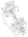
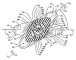
도 1 은 연결 허브 안으로 그에 부착되어야 하는 카테테르의 자유 단부를 받아들이려고 하는 카테테르 수용 상태에서 도시된 본 발명의 원리를 구체화시키는 연결 허브의 사시도이다.1 is a perspective view of a connecting hub embodying the principles of the present invention shown in a catheter receiving state trying to receive a free end of a catheter to be attached thereto into the connecting hub.
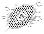
도 2 는 도 1 의 카테테르의 자유 단부에 부착된 카테테르 포획 상태(capture condition)에서 도 1 의 연결 허브에 대한 사시도이다.FIG. 2 is a perspective view of the connection hub of FIG. 1 in a catheter capture condition attached to the free end of the catheter of FIG. 1. FIG.
도 3 은 도 2 에 도시된 카테테르 포획 상태에서 도 1 및 도 2 의 연결 허브의 요소들을 걸쇠 결합시키는(latch) 도 1 의 연결 허브의 구조들에 대한 확대된 부분 사시도이다.FIG. 3 is an enlarged partial perspective view of the structures of the connection hub of FIG. 1 latching elements of the connection hub of FIGS. 1 and 2 in the catheter capture state shown in FIG.
도 4 는 선 4-4를 따라서 취한 도 2 의 연결 허브에 대한 횡단면도로서, 도 2 에 도시된 카테테르 포획 상태에서 도 1 및 도 2 의 연결 허브의 요소들에 걸쇠 결합되도록 상호 작용하는 도 3 에 도시된 구조들을 묘사하고 있다.FIG. 4 is a cross-sectional view of the connection hub of FIG. 2 taken along lines 4-4, interacting to latch the elements of the connection hub of FIGS. 1 and 2 in the catheter trap shown in FIG. It depicts the structures shown in.
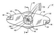
도 5 는 도 1 및 도 2 의 연결 허브의 분해된 평면도이다.5 is an exploded plan view of the connection hub of FIGS. 1 and 2;
도 6 은 선 6-6 의 사시도로부터 취한 도 5 의 연결 허브의 유체 결합 요소들에 대한 정면도이다.6 is a front view of the fluid coupling elements of the connecting hub of FIG. 5 taken from the perspective view of lines 6-6.
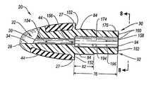
도 7 은 선 7-7을 따라서 취한 도 5 및 도 6 에 도시된 유체 결합 요소들의 길이 방향 단면도이다.7 is a longitudinal cross-sectional view of the fluid coupling elements shown in FIGS. 5 and 6 taken along line 7-7.
도 8 은 절단선 8-8 의 사시도로부터 취한 도 5 의 연결 허브의 카테테르 수용 요소의 정면도이다.8 is a front view of the catheter receiving element of the connecting hub of FIG. 5 taken from the perspective view of cut line 8-8.
도 9 는 절단선 9-9를 따라서 취한 도 5 및 도 8 의 카테테르 수용 요소의 길이 방향 단면도이다.9 is a longitudinal cross-sectional view of the catheter receiving element of FIGS. 5 and 8 taken along cut line 9-9.
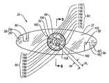
도 10 은 절단선 10-10을 따라서 취한 도 1 의 연결 허브의 길이 방향 단면도로서, 카테테르 수용 상태에서 연결 허브 요소들의 내부 구조들의 상호 작용을 도시한다.10 is a longitudinal cross-sectional view of the connecting hub of FIG. 1 taken along cut line 10-10, illustrating the interaction of the internal structures of the connecting hub elements in the catheter receiving state.
도 11 은 도 10에서 절단선 11-11을 포함한 것으로부터 보다 명확하게 이해되는 위치에서 절단선 11-11을 따라서 취한 도 1 의 연결 허브의 횡단면도이다.FIG. 11 is a cross-sectional view of the connecting hub of FIG. 1 taken along cut line 11-11 at a position that is more clearly understood from including cut line 11-11 in FIG. 10.
도 11a 및 도 11b 는 도 10 및 도 11 의 연결 허브의 카테테르 수용 상태의 내부 구조들에 대한 횡단면의 시퀀스를 나타낸 것으로서 이들은 도 12 및 도 13 에 도시도니 바와 같은 연결 허브의 카테테르 포착 상태로의 점증하는 상대 회전을 겪고 있다.11A and 11B show a cross sectional sequence of internal structures of the catheter receiving state of the connecting hub of FIGS. 10 and 11, which show the catheter trapping state of the connecting hub as shown in FIGS. 12 and 13. Is experiencing an increasing relative turn.
도 12 는 절단선 12-12를 따라서 취한 도 2 의 연결 허브의 길이 방향 절단면도로서, 카테테르 포획 상태에서 연결 허브의 요소들에 대한 내부 구조의 상호 작용을 도시한다.FIG. 12 is a longitudinal cutaway view of the connecting hub of FIG. 2 taken along cut line 12-12, illustrating the interaction of the internal structure with the elements of the connecting hub in the catheter trapped state.
도 13 은 도 12 의 절단선 13-13을 포함한 것으로부터 보다 명확하게 이해되는 위치에서 절단선 11-11을 따라서 취한 도 2 의 연결 허브의 횡단면도이다.FIG. 13 is a cross-sectional view of the connecting hub of FIG. 2 taken along cut line 11-11 at a position that is more clearly understood from including cut line 13-13 of FIG. 12.
도 14a 및 도 14b 는, 연결 허브의 카테테르 포획 상태로, 점진적으로 증가하는 상대 회전을 겪고 있는 연결 허브의 대안의 구현예에서 카테테르 수용 상태에 대한 구현예의 내부 구조를 횡단면도의 연속으로 나타낸 것이다.14A and 14B show in a cross sectional view the internal structure of an embodiment for a catheter receptive state in an alternative embodiment of a connecting hub that is undergoing a progressively increasing relative rotation with a catheter capture of the connecting hub. .
도 15a 및 도 15b 는, 연결 허브의 카테테르 포획 상태로, 점진적으로 증가하는 상대 회전을 겪고있는 연결 허브의 대안의 구현예에서 카테테르 수용 상태에 대한 구현예의 내부 구조를 횡단면도의 연속으로 나타낸 것이다.15A and 15B show, in cross-sectional views, the internal structure of an embodiment for a catheter receiving state in an alternative embodiment of a connecting hub that is undergoing a progressively increasing relative rotation with a catheter capture of the connecting hub. .
도 16 은 카테테르 수용 요소를 차폐하는 유체 결합 요소 각도 부분을 포함하는 연결 허브의 구현예에 대한 사시도를 나타낸 것이다.16 shows a perspective view of an embodiment of a connection hub that includes a fluid coupling element angular portion that shields the catheter receiving element.
도 17 은 유체 결합 요소와 카테테르 수용 요소를 포함하는 타원형 연결 허브의 구현예에 대한 사시도를 나타낸 것이다.17 shows a perspective view of an embodiment of an elliptical connection hub that includes a fluid coupling element and a catheter receiving element.
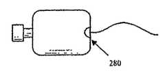
도 18 은 유체 결합 요소와 카테테르 수용 요소를 포함하는 정사각형 연결 허브의 구현예에 대한 사시도를 나타낸 것이다.18 shows a perspective view of an embodiment of a square connecting hub that includes a fluid coupling element and a catheter receiving element.
도 19 는 유체 결합 요소와 카테테르 수용 요소를 포함하는 다이아몬드 연결 허브의 구현예에 대한 사시도를 나타낸 것이다.19 shows a perspective view of an embodiment of a diamond connection hub that includes a fluid coupling element and a catheter receiving element.
도 20 은 유체 결합 요소와 카테테르 수용 요소를 포함하는 아치형 연결 허브의 구현예에 대한 사시도를 나타낸 것이다.20 shows a perspective view of an embodiment of an arcuate connection hub that includes a fluid coupling element and a catheter receiving element.
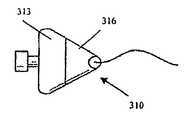
도 21a 및 도 21b 는 유체 결합 요소와 카테테르 수용 요소를 포함하는 3 각형 연결 허브의 구현예들에 대한 사시도를 나타낸 것이다.21A and 21B show perspective views of embodiments of a triangular connection hub that includes a fluid coupling element and a catheter receiving element.
도 22a 및 도 22b 는 유체 결합 요소와 카테테르 수용 요소를 포함하는 연결 허브의 구현예에 대한 사시도를 나타낸 것으로서, 여기에서 캡은 연결 허브의 구현예로부터 각도를 가지고 연장된다.22A and 22B show perspective views of an embodiment of a connection hub comprising a fluid coupling element and a catheter receiving element, wherein the cap extends at an angle from the embodiment of the connection hub.
개관하면, 도 1 은 본 발명의 원리를 구현한 연결 허브(hub, 10) 및 카테테르(12)를 나타내며, 카테테르의 자유 단부(14)는, 자유 단부로부터 카테테르(12) 내부와의 선택적인 유체 소통이 이루어질 수 있게 하는 목적을 위해서 허브에 부착된다. 도 1 에 도시된 것의 외부로부터 명백한 연결 허브(10)의 제 1 구성 요소 및 제 2 구성 요소는 서로에 대하여 동일 축선상(coaxial)에서 회전되게 연결될 수 있도록 맞닿은 관계로 고정된 유체 결합 요소(22)와 카테테르 수용 요소(20)를 포함한다. 그러한 상대 회전(R22)은 도 1에서 화살표로 표시되어 있는데, 상기 화살표는, 일단 도 1 에 도시된 화살표(S)에 제시된 방식으로 카테테르(12)가 연결 허브(10)에 진입하였다면, 연결 허브(10)를 카테테르(12)에 부착시키기 위하여 유체 결합 요소(22)가 카테테르 수용 요소(20)에 상대적으로 회전되는 방향으로 배향된다.In overview, FIG. 1 shows a connecting hub (hub) 10 and a
도 1 에 도시되지 않은 연결 허브(10)의 내부 구조들은 실제로 카테테르 수용 요소(20)와 유체 결합 요소(22)의 서로 회전 연결을 이룬다. 다른 내부 구조들은 카테테르(12)의 자유 단부(14)를 기계적으로 파지하고 그 외부 둘레에 유체 시일을 설정함으로써 연결 허브(10)를 카테테르(12)에 부착하는 역할을 한다.The internal structures of the
그럼에도 불구하고, 도 1 에 도시된 수용 요소(20)의 일부는 카테테르 수용 요소(20)를 위한 제 1 작동 핸들(26)의 형태를 취한다. 제 1 작동 핸들(26)은 카테테르 수용 요소(20)의 평면(P20)을 형성하는 전체적으로 평탄한 외관을 가진다. 도시된 구현예에서, 작동 핸들에 대하여 다른 대안의 평탄한 형상이 본 발명의 원리와 일치하게 이용될 수 있을지라도, 제 1 작동 핸들(26)은 평탄화된 제 1 반원형 디스크이다. 제 1 작동 핸들(26)은 유체 결합 요소(22)에 근접한 제 1 맞닿음 단부(27) 및, 제 1 외측 단부(28)를 가지는데, 제 1 외측 단부는 카테테르(12)의 자유 단부(14)를 연결 허브(10) 안으로 미끄러지게 수용하도록 형성된다. 연결 허브(10) 안으로 카테테르(12)의 자유 단부(14)를 진입시키는 것은, 도 1 에 도시된 측부에서 제 1 작동 핸들(26)의 제 1 외측 단부(28) 안으로 오목하게 되어 있는, 깔때기 형상의 개방된 상부 안내로(guideway, 32)의 협소한 종단부에 위치된 접근 개구(30)에 의해 발생된다. 따라서 안내로(32)는 카테테르 수용 요소(20)의 평면(P20)에 평행한 쐐기 형상의 바닥부(34)를 가진다. 안내로(32)의 이러한 형상은 의료 종사원이 카테테르 수용 요소(20)의 평면(P20)내에 있는 접근 개구(30)를 관찰할 필요 없이 카테테르(12)의 자유 단부(14)를 연결 허브(10) 안으로 진입시킬 수 있게 한다.Nevertheless, part of the
도 1 에 도시된 유체 결합 요소(22)의 일부는 유체 결합 요소(22)를 위한 제 2 작동 핸들(36)의 형태를 취한다. 제 2 작동 핸들(36)은 유체 결합 요소(22)의 평면(P22)을 형성하는 전체적으로 평탄한 외관을 가진다. 도시된 구현예에서, 비록 작동 핸들의 다른 평탄한 형상들이 본 발명의 원리에 따라서 이용될 수 있을지라도, 제 2 작동 핸들(36)은 평탄화된 제 2 반원형 디스크이다. 유체 결합 요소(22)는 카테테르 수용 요소(20)에 근접한 제 2 맞닿음 단부(39) 및, 그로부터 이격된 제 2 외측 단부(40)를 가지며, 제 2 외측 단부는 연결 허브(10)가 부착되는 그 어떤 카테테르의 자유 단부와도 연결 허브(10)를 통하여 선택적인 유체 소통을 이루도록 구성된다. 그러한 단부를 향하여, 유체 결합 요소(22)에는 제 2 외측 단부(40)에 제 2 작동 핸들(36)로부터 반경 방향 외측으로 연장된 넥크(neck, 38)가 제공된다. 넥크(38)의 자유 단부는 그에 부착된 그 어떤 카테테르의 자유 단부와도 연결 허브(10)를 통하여 선택적인 유체 소통이 이루어질 수 있도록 설계된다. 그러나, 도 1 에 있어서, 넥크(38)의 자유 단부는 캡(42) 때문에 눈에 띄지 않으며, 캡은 그러한 유체 소통을 억제하도록 넥크(38)의 자유 단부로 나사 결합되었다.Part of the
도 1 에 있어서, 유체 결합 요소(22)의 평면(P22)은 카테테르 수용 요소(20)의 평면(P20)에 동일 평면상에 있지 않은 관계이다. 그러나, 유체 결합 요소(22)의 평면(P22)과 카테테르 수용 요소(20)의 평면(P20) 사이의 오정렬(nonalignment)의 정도는 회전(R22)과 관련된 화살표로 표시된 방향에서 카테테르 수용 요소(20)에 대하여 유체 결합 요소(22)의 회전(R22)을 통하여 감소될 수 있다. 그것은 접근 개구(30)를 통하여 연결 허브(10) 안으로 수용되었던 카테테르의 자유 단부로 연결 허브(10)를 실제로 부착시키기 위하여 발생되는 조작이다. 제 1 작동 핸들(26)로서의 카테테르 수용 요소(20)의 평탄한 외부 형상 및 제 2 작동 핸들(36)로서의 유체 결합 요소(22)의 평탄한 외부 형상은 카테테르 수용 요소(20) 및 유체 결합 요소(22) 사이의 상대적인 회전을 용이하게 한다.In FIG. 1, the plane P22 of the
카테테르 수용 요소(20) 및 유체 결합 요소(22)는, ABS, 폴리카보네이트, 렉산(lexan), 폴리아미드, 나일론, PE 또는 ABS-폴리카보네이트 혼합물과 같은, 상대적으로 경질의 성형 가능한 플라스틱을 포함할 수 있다. 그러한 재료들은 구조적으로 단단하지만 부숴지기 쉽지 않은 조직의 제품을 생산하는 공지의 제조 과정으로 용이하게 형성된다. 그러한 재료들로 제작된 얇은 구조들은 소망스러운 탄성 변형의 정도를 나타내도록 만들어질 수도 있다.The
카테테르 수용 요소(20)의 제 1 작동 핸들(26)의 외부 표면에는 하나 이상의 상감 영역(inlay regions;象嵌 領域, 44)들이 제공될 수 있는데, 이러한 영역들은 카테테르 수용 요소(20)의 나머지가 나타내는 재료 특성과 대조적인 재료 특성들을 가진다. 마찬가지로, 유체 결합 요소(22)의 제 2 작동 핸들(36)의 외부 표면에는 하나 이상의 상감 영역(46)들이 제공될 수 있는데, 이들은 유체 결합 요소(22)의 나머지가 포함되는 재료의 특성들에 대조적인 특성을 가진 재료로 제작된다. 각각의 상감 영역(44,46)들이 포함할 수 있는 재료들중 하나의 재료는, Krayton, 열가소성 고무, SAN, TPR, TPU 또는 Santoprene 과 같은, 부드럽고 피부에 적용 가능한 재료이다. 연결 허브(10)의 요소들중 외부 표면들상에서, 상감 영역(44,46)들과 같은 부위에서 그러한 연성 재료를 이용하는 것은, 유체 결합 요소(22)의 회전(R22)을 야기하는 유체 결합 요소(22)의 제 2 작동 핸들(36) 및 카테테르 수용 요소(20)의 제 1 작동 핸들(26)을 조작하는 의료 인원이 구매를 가능하게 하는데 적극적으로 기여한다. 또한 상감 영역(44,46)들은 연결 허브(10)가 피부에 대하여 놓여졌을 때 환자의 안락함에도 기여한다.The outer surface of the first actuating handle 26 of the
카테테르 수용 요소(20)의 제 1 작동 핸들(26)의 제 1 맞닿음 단부(27) 및 유체 결합 요소(22)의 제 2 작동 핸들(36)의 제 2 맞닿음 단부(39)에는 걸쇠(50)들이 제공되는데, 걸쇠들 각각은 카테테르 수용 요소(20)와 유체 결합 요소(22) 각각에 반대편의 관계로 위치된 쌍을 이룬 갈고리(52) 및 눈부분(eye, 54)을 구비한다. 걸쇠(50)들은 유체 결합 요소(22)와 카테테르 수용 요소(20) 사이에 가능한 상대적인 회전의 범위를 제한한다. 일단 카테테르 수용 요소(20)에 대한 유체 결합 요소(22)의 회전(R22)이 연결 허브(10)로 하여금 카테테르 자유 단부에 부착되게 하였다면 걸쇠(50)들이 맞물리며, 그러한 상태는 이후에 연결 허브(10)의 요소들의 카테테르 포착 상태로서 지칭될 것이다. 일단 맞물리면, 걸쇠(50)들은 연결 허브(10)의 카테테르 포착 상태를 벗어나서 유체 결합 요소(22)와 카테테르 수용 요소(20)가 부주의로 제거되는 것을 방지한다.The
도 2 는 연결 허브(10)의 카테테르 포착 상태를 도시한다. 여기에서, 결합 요소(22)의 평면(P22)은 카테테르 수용 요소(20)의 평면(P20)과 동일 평면에 있는 관계가 되기에 충분한 정도로 카테테르 수용 요소(20)에 대한 회전(R22)을 받았다. 그에 대응하여, 연결 허브(10)는 카테테르 포착 상태에서 연결 허브(10)의 평면(P10)을 형성하는 전체적으로 평탄한 외관을 취한다.2 shows the catheter trapped state of the
도 2 에 있어서, 캡(42)이 도시되어 있는데 이것은 유체 결합 요소(22)의 목부분(38)의 자유 단부에 대하여 나사화되어 있다. 결과적으로, 목부분(38)의 자유 단부상에는 표준 루어 연결부(58)가 나타나는데, 루어 연결부(luer connector)에 의하여 보조적인 의료 장비를 연결 허브(10)를 통하여 카테테르(12)와 유체 소통 상태로 둘 수 있다. 연결 허브(10)의 카테테르 포착 상태에서, 카테테르 수용 요소(20)의 제 1 작동 핸들(26)의 제 1 맞닿음 단부(27)는 유체 결합 요소(22)의 제 2 작동 핸들(36)의 제 2 맞닿음 단부(39)와 일치하게 면-대-면(face-to-face) 맞물림 상태가 된다. 연결 허브(10)는 전체적으로 원형 디스크의 외관을 취하며 목부분(38)이 그로부터 반경 방향으로 돌출하고 있다. 카테테르 수용 요소(20)와 유체 결합 요소(22)는 걸쇠(50)들의 눈부분(54)과 갈고리(52)의 상호 작용에 의하여 연결 허브(10)의 카테테르 포착 상태로부터 쉽사리 벗어나는 것이 제한된다. 그러한 구조들의 전형적인 설정은 도 3 및 도 4에서 보다 상세하게 도시된다.In FIG. 2, a
도 3 은 도 1 에 도시된 연결 허브(10)의 카테테르 수용 상태에 대응한다. 후크(52)는 카테테르 수용 요소(20)의 작동 핸들(16)의 외부에 있는 요부(65) 안에 하우징된 미늘(barb,64)을 가진 샤프트(62)를 구비한다. 유체 결합 요소(22)상의 눈부분(54)은 포착 표면(66)을 에워싸는데, 포착 표면에는 샤프트(62)상의 미늘(64)에 대하여 후크(52)의 형상 및 위치와 보완 관계에 있는 멈춤부(68)가 제공된다. 카테테르 수용 요소(22)와 유체 결합 요소(22)가 연결 허브(10)의 카테테르 포착 상태를 향하여 회전되면, 후크(52)들이 눈부분(54)에 진입한다. 미늘(64)은 포착 표면(66)을 따라서 지탱되어, 포착 표면(66)으로부터 이탈되게 후크(52)의 샤프트(62)를 탄성 변형시킨다. 일단 카테테르 수용 요소(20)와 유체 결합 요소(22)가 연결 허브(10)의 카테테르 포착 상태에서 동일 평면의 배향에 도달하면, 미늘(64)은 멈춤부(68)에 도달하고 그 안으로 탄성적으로 걸리게 된다. 이러한 관계는 도 4 에 횡단면으로 도시되어 있다. 따라서 걸쇠(50)들은 유체 결합 요소(22) 및 카테테르 수용 요소(20)의 상대적인 회전에 대한 정지부로서의 역할을 하며, 걸쇠(50)들은 카테테르 포착 상태를 벗어나는 부주의한 이탈에 대하여 연결 허브(10)의 이들 요소들을 제한한다.FIG. 3 corresponds to the catheter acceptance state of the
도 5 는 연결 허브(10)의 부가적인 특징들을 나타내는 연결 허브(10)의 요소들에 대한 분해된 평면도를 도시한다.5 shows an exploded top view of the elements of the
카테테르 수용 요소(20)의 제 1 작동 핸들(26)은 도 5 에 도시되어 있으며 반원형의 외측의 외주(periphery,70)를 가지는 것으로서, 외측 주위는 그것의 제 1 맞닿음 단부(27)에 있는 선형의 직경 방향 부분(74) 및 제 1 작동 핸들(26)의 제 1 외측 단부(28)를 둘러싸는 원호형 부분(72)을 포함한다. 또한 도 5 에는 기둥 형상의 구조부(76)가 도시되어 있는데, 구조부는 맞닿음 부분을 따른 중앙 위치로부터 제 1 작동 핸들(26)의 제 1 맞닿음 단부(27)에 수직으로 돌출한다. 기둥 형상 구조부(76)의 베이스는 실린더형의 축(82)으로서, 이것은 의료 위치에서 연속적이고 상승된 보유 융기(84)에 의하여 둘레가 감싸인다. 유체 결합 요소(22)의 내부에 있는 대응 구조와 함께 작용하는 축(82) 및 보유 융기(84)는 상대적인 회전 관계로 카테테르 수용 요소(20)와 유체 결합 요소(22)를 고정시키는데, 이러한 관계는 도 1 에 도시된 카테테르 수용 상태의 연결 허브(10)를 도 2 에 도시된 카테테르 포착 상태로 변환시키는 것을 허용한다.The first actuation handle 26 of the
제 1 클램핑 조오(90) 및 제 2 클램핑 조오(92)는 축(82)으로부터 정렬된 상태로 돌출된다. 제 1 및 제 2 클램핑 조오(90,92)들은 신장된 홈(94)에 의해 분리되는데, 상기 신장된 홈은 기둥 형상의 구조부(76)를 직경 방향으로 가로지르고 그것을 통해 길이 방향으로 축(83)안에서 보유 융기(84)까지 연장된다.The
도 5에서 처음으로 나타나는 연결 허브(10)의 추가적인 요소는 튜브형의 시일링 슬리이브(100)이다. 시일링 슬리이브(100)는 합성 폴리이소프렌(polyisoprene), TPR, TPU, SAN, Santoprene, 라텍스 또는 고무이다. 시일링 슬리이브(100)는 카테테르의 자유 단부와 가장 밀접하게 상호 작용하는 연결 허브(10)의 요소로서, 상기 자유 단부는 연결 허브(10)에 부착된다. 카테테르 수용 요소(20)와 유체 결합 요소(22)가 도 1 및 도 2 에 도시된 바와 같이 조립되었을 때 시일링 슬리이브(100)는 제 1 클램핑 조오(90)와 제 2 클램핑 조오(92) 사이에 하우징된다. 이러한 상황하에서, 축(82), 제 1 및 제 2 클램핑 조오(90,92)들 및 시일링 슬리이브(100)는 도 5 에 점선으로 도시된 유체 결합 요소(22)의 내부 공간(104) 안으로 진입한다.An additional element of the connecting
도 5 에 나타난 평면도에서, 유체 결합 요소(22)의 제 2 작동 핸들(36)의 외주(110)는 전체적으로 반원형의 형상으로서, 유체 결합 요소(22)의 제 2 맞닿음 단부(39)에 형성된 선형의 직경 방향 부분(112) 및, 유체 결합 요소(22)의 제 2 작동 핸들(36)의 제 2 외측 단부(40)에서 목 부분(38)에 의해 중단된 점선의 원호형 부분(116)을 포함한다.In the top view shown in FIG. 5, the
유체 결합 요소(22)의 내부 공간(104)에 대한 보다 낳은 이해는 도 6 및 도 7을 함께 참조함으로써 얻을 수 있다. 여기에서, 유체 결합 요소(22)의 제 2 작동 핸들(36)의 외주(110)의 직경 방향 부분(112)은 제 2 맞닿음 단부(39)에 위치되어 있는 제 2 작동 핸들(36)의 평탄한 인터페이스 표면(118)에 대응한다. 인터페이스 표면(118)의 중앙으로 개방된 것은 실린더형 구멍(120)으로서, 상기 실린더형 구멍은 연속적인 보유 홈(122)에 의해 둘러싸인다. 구멍(120) 및 보유 홈(122)은, 카테테르 수용 요소(20)와 유체 결합 요소(22)가 도 1 및 도 2 에 도시된 바와 같은 맞닿음으로 조립되었을 때, 축(82)의 외부에 있는 보유 융기부(84)가 보유 홈(122) 안으로 딸깍 물리게금 수용될 수 있도록 크기가 정해진다.A better understanding of the
구멍(120)을 통한 유체 결합 요소(22)의 외부로의 개방은 같은 길이의 수직 벽(132,134,136,138)들에 의해 경계가 정해진 클램프 작동 소켓(130)에 의해 이루어진다. 따라서, 클램프 작동 소켓(130)은 정사각형으로서 도 6에서 가장 유리하게 도시된 횡단 단면 형상을 가진다. 도 7 에 도시된 바와 같이, 클램프 작동 소켓(130)은 제 2 맞닿음 단부(39)를 향하는 제 1 단부 및, 제 2 맞닿음 단부(39)의 반대편에 있는 제 2 단부를 가진다.Opening of the
구멍(120)으로부터 반대편인 클램프 작동 소켓(130)의 단부는 3 개의 동일한 축 선상으로 배치되고 감소되는 직경의 3 개의 일련의 공간을 통하여 루어 연결부(58)의 내부(140)와 소통된다. 클램프 작동 소켓(130)으로부터 루어 연결부(58)의 내부(140)를 향하면서, 이들 실린더형 공간들은, 제 1 시일링 슬리이브 맞닿음 챔버(142), 제 2 소형 카테테르 맞닿음 챔버(144) 및, 마지막으로, 루어 연결부(58)의 내부(140)로부터 카테테르 맞닿음 챔버(144) 안에 머무르는 그 어떤 카테테르의 자유 단부의 내부로의 유체 소통을 충족시키도록 계산된 매우 작은 유체 통로(146)를 포함한다.The end of the
제 1 작동 핸들(26)의 제 1 맞닿음 단부(27)로부터 돌출된 기둥 형상 구조부(76)에 대한 이해는 도 8 및 도 9를 참조함으로써 얻어질 수 있다. 여기에서, 제 1 작동 핸들(26)의 외주(70)의 직경 부분(74)은 평탄한 인터페이스 표면(152)에 대응하며 인터페이스 표면으로부터 기둥형 구조부(76)가 중앙으로 돌출한다는 점이 우선 이해되어야 한다. 카테테르 수용 요소(20)의 제 1 작동 핸들(26)을 통하여 중앙에 형성된 것은 카테테르 통로(154)로서, 이것은 제 1 작동 핸들(26)의 제 1 외측 단부(28)에 있는 접근 개구(30)로부터 제 1 맞닿음 단부(27)에 있는 내측 개구(156)로 연장된다. 내측 개구(156)에서, 카테테르 통로(154)는 기둥형 구조부(76)의 전체 길이를 통하여 중앙으로 연장된 커다란 시일링 슬리이브 수용 챔버(158) 안으로 개방되어, 제 1 및 제 2 클램핑 조오(90,92)들 사이의 홈(94)을 포함하는 것으로 이전에 식별된 기둥형 구조부(76) 내부의 지나간 공간을 공유한다.An understanding of the
도 1 및 도 2 에 도시된 연결 허브(10)의 조립 상태에서, 카테테르 맞닿음 챔버(144)로부터 멀리 있는 시일링 슬리이브(100)의 단부에는 카테테르 수용 요소(20)의 제 1 작동 핸들(26)에 있는 카테테르 통로(154)에 직접적으로 면하는 내측 개구(156)가 배치되어 있다. 시일링 슬리이브(100), 수용 챔버(158) 및, 카테테르 맞닿음 챔버(144)는, 시일링 슬리이브(100)의 전체 길이를 수용하기 위하여, 그리고 유체 결합 요소(22)내 내부 공간(104)의 카테테르 맞닿음 챔버(144)와 제 1 작동 핸들(26)내 카테테르 통로(154) 사이에서 시일링 슬리이브(100)의 내부 통로를 정렬시키도록 서로 배향되기 위하여, 크기가 정해진다.In the assembled state of the
기둥형 구조부(176)의 이들 관계들의 결과로서, 제 1 및 제 2 클램핑 조오(90,92)들은 내측 개구(156)의 양쪽 측부들에 있는 제 1 작동 핸들(26)의 제 1 맞닿음 단부(27)로부터 카테테르 통로(154)로 돌출하는 것이 이해될 수 있다. 제 1 및 제 2 클램핑 조오(90,92)들은 제 1 작동 핸들(26)의 제 1 맞닿음 단부(27)로부터 같은 간격에서 끝나게 된다. 따라서 제 1 클램핑 조오(90)는 제 1 클램프 첨단부(160)에서 끝나고, 제 2 클램핑 조오(92)는 제 2 클램프 첨단부(162)에서 끝난다.As a result of these relationships of the
도 8을 참조함으로써 가장 용이하게 이해되는 바로서, 제 1 클램핑 조오(90)는 넓고 평탄한 외측 표면(166)과 평행하고 평탄한 내측 클램프 표면(168)에 의해 둘러싸인 신장된 평탄 구조체이다. 외측 표면(166) 및 클램프 표면(168)은 그것의 단부들에서 개별의 짧은 측부 표면(170,172)들에 의하여 연결된다. 따라서 제 1 클램핑 조오(90)의 클램프 표면(168)은 제 1 및 제 2 클램핑 조오(90,92)들 사이의 기둥형 구조부(76)에 있는 홈(94)의 일측을 형성한다.As best understood by reference to FIG. 8, the
도 8 및 도 9 에 도시된 홈(94)의 폭(W1)보다 큰 시일링 슬리이브 수용 챔버(158)내 직경과 조합하여, 홈(94)과 공유된 공간에 있는 기둥형 구조부(76)의 중심에 시일링 슬리이브 수용 챔버(158)를 위치시키는 것은, 반원형 단면의 길이 방향으로 연장되고 단부가 개방된 카테테르 수용 요부(174)에 의하여 제 1 클램핑 조오(90)의 클램프 표면(168)이 중앙으로 횡단되는 결과를 초래한다. 도 8 및 도 9 에서와 같이, 제 1 클램핑 조오(90)가 외력의 영향으로부터 자유로울 때, 카테테르 수용 요부(174)는 카테테르 통로(154)로의 내측 개구(156)와 정렬된다. 도시된 구현예에서, 제 1 클램핑 조오(90)의 횡단 단면 형상은 그 전체 길이를 따라서 변화하지 않는다.
특히, 연결 허브(10)를 카테테르 자유 단부에 부착시키는데 있어서, 제 1 클램핑 조오(90)의 작용에 비하여, 제 1 클램핑 조오(90)의 외측 표면(166) 및 그것의 단부 표면(170)은 만곡된 베어링 표면(176)에 의하여 매끄러운 접선으로 서로 연결된다. 마찬가지로, 제 1 클램핑 조오(90)의 외측 표면(166)과 그것의 단부 표면(172)은 만곡된 베어링 표면(178)에 의하여 매끄러운 접선으로 상호 연결된다.In particular, the
제 2 클램핑 조오(92)는 제 1 클램핑 조오(90)와 동일하게 구성된다. 따라서, 제 1 클램핑 조오(90)는 평행하고 평탄한 내측 클램프 표면(188) 및 넓고 평탄한 외측 표면(186)에 의해 둘러싸인 신장된 평면 구조이다. 외측 표면(186)과 클램프 표면(188)은 그것의 단부들에서 개별적인 짧은 측부 표면(190,192)에 의해 연결된다. 제 2 클램핑 조오(92)의 내측 클램프 표면(198)은 제 1 및 제 2 클램핑 조오(90,92)들 사이의 기둥형 구조부(96)에 있는 홈(94)의 일 측부를 형성한다.The
도 8 및 도 9 에 도시된 홈(94)의 폭(W1)보다 큰 시일링 슬리이브 수용 챔버(158)내 직경과 조합하여, 홈(94)과 공유된 공간에 있는 기둥형 구조부(76)의 중심에 시일링 슬리이브 수용 챔버(158)를 위치시키는 것은, 반원형 단면의 길이 방향으로 연장되고 단부가 개방된 카테테르 수용 요부(194)에 의하여 제 1 클램핑 조오(90)의 클램프 표면(188)이 중앙으로 횡단되는 결과를 초래한다. 도 8 및 도 9 에서와 같이, 제 2 클램핑 조오(92)가 외력의 영향으로부터 자유로울 때, 카테테르 수용 요부(194)는 카테테르 통로(174)로의 내측 개구(156)와 정렬된다. 도시된 구현예에서, 제 2 클램핑 조오(92)의 횡단 단면 형상은 그 전체 길이를 따라서 변화하지 않는다.
특히, 연결 허브(10)를 카테테르 자유 단부에 부착시키는데 있어서 제 2 클램핑 조오(92)의 작용에 비하여, 제 2 클램핑 조오(92)의 외측 표면(186) 및 그것의 단부 표면(190)은 만곡된 베어링 표면(196)에 의하여 매끄러운 접선으로 서로 연결된다. 마찬가지로, 제 2 클램핑 조오(92)의 외측 표면(186)과 그것의 단부 표면(192)은 만곡된 베어링 표면(198)에 의하여 매끄러운 접선으로 상호 연결된다. 카테테르(12)의 자유 단부(14)는 카테테르 수용 요소(20)내 카테테르 통로(154)를 통하여, 시일링 슬리이브(100)의 전체 길이를 통해서 카테테르 맞닿음 챔버(144) 안으로 미끌어져 들어갔다.In particular, compared to the action of the
도 10 및 도 11 은 도 1 에 도시된 카테테르 수용 상태에서 연결 허브(10)의 요소들에 대한 단면들을 나타낸다.10 and 11 show cross sections of the elements of the
도 10 에 있어서, 카테테르 수용 요소(20)의 제 1 작동 핸들(26)의 제 1 맞닿음 단부(27)에 있는 인터페이스 표면(152)은 유체 결합 요소(22)의 제 2 작동 핸들(36)의 제 2 맞닿음 단부(39)에서 인터페이스 표면(118)과 맞물린다. 시일링 슬리이브(100)를 사이에 가진 제 1 및 제 2 클램핑 조오(90,92)들은 유체 결합 요소(22) 내부의 클램프 작동 소켓(130) 안에 수용된다.In FIG. 10, the
유체 결합 요소(22)는 도 11에서 화살표로 표시된 바와 같이 카테테르 수용 요소(20)에 대하여 회전(R22) 할 수 있다. 그러나, 그러한 회전 이전에, 유체 결합 요소(22)의 평면(P22)은 카테테르 수용 요소(20)의 평면(P20)에 대하여 약 45°의 예각(A1)으로 배치된다. 제 1 및 제 2 클램핑 조오(90,92)들은 그 사이에 있는 홈(94)이 감소되지 않은 폭(W1)을 가지고 있으면서 개방 상태에 있다. 클램프 작동 소켓(130)의 벽(132)은 제 1 클램핑 조오(90)의 외측 표면(66)에 대향하고, 클램프 작동 소켓(130)의 벽(136)은 제 2 클램핑 조오(92)의 외측 표면(86)에 대향한다. 클램프 작동 소켓(130)의 벽(134)은 제 1 클램핑 조오(90)의 측부 표면(170), 제 2 클램핑 조오(92)의 측부 표면(192) 및 그 사이에 위치된 홈(94)으로의 진입부에 대향한다. 클램프 작동 소켓(130)의 벽(138)은 제 1 클램핑 조오(90)의 측부 표면(172), 제 2 클램핑 조오(92)의 측부 표면(190) 및 그 사이에 위치된 홈(94)으로의 개구에 대향한다.The
도 11a 및 도 11b 는 도 11 의 중앙 부분에 대한 확대된 횡방향 단면도의 시퀀스(sequence)를 도시한 것으로서, 카테테르 수용 요소(20)에 대한 유체 결합 요소(22)의 점진적인 회전(R22) 동안에 클램프 작동 소켓(30)의 요소들과 제 1 및 제 2 클램핑 조오(90,92)들에 의해 상대적으로 취해지는 위치들을 나타낸다.11A and 11B show an enlarged transverse cross sectional sequence of the central portion of FIG. 11, with the progressive rotation R22 of the
카테테르 수용 요소(20)의 평면(P20)은 도 11a 및 도 11b 에 각각 도시되어 있으며, 그에 의하여 이해되는 바로서, 카테테르 수용 요소(20) 및 제 1 및 제 2 클램핑 조오(90,92)들과 같은 그것의 모든 요소들이 도 11 에 도시된 것과 같은 배향으로 유지되는 반면에, 유체 결합 요소(22)의 내부 특징이 되는 클램프 작동 소켓(130)은 그에 대한 동일 축선상의 회전(R22)으로 맞물린다. 도 11a 및 도 11b 의 시퀀스로 도시된 클램프 작동 소켓(130)의 상대적인 회전은 제 1 클램핑 조오(90)를 점진적으로 제 2 클램핑 조오(92)에 근접하게 강제하는 역할을 하여, 과정중에 카테테르(12)의 자유 단부(14) 둘레에서 시일링 슬리이브(100)를 압축한다.The plane P20 of the catheter receiving element20 is shown in FIGS. 11A and 11B, respectively, as understood by the
도 11a에서, 유체 결합 요소(22)의 평면(P22)은 도 11 에 도시된 위치로부터 약 15°로써 카테테르 수용 요소(20)에 대한 회전(R22)으로 맞물리도록 되어 있다. 결과적으로, 유체 결합 요소(22)의 평면(P22)과 카테테르 수용 요소(20)의 평면(P20) 사이의 각도(A2)는 단지 대략 30°이다. 클램핑 조오들 사이에 배치된 시일링 슬리이브(100) 뿐만 아니라, 제 1 및 제 2 클램핑 조오(90,92)들과 같은 카테테르 수용 요소(20)의 구성 요소들은 과정중에 정지 상태로 유지되지만, 클램프 작동 소켓(130)은 그에 대하여 대략 15°로 회전되었다. 결과적으로, 작동 소켓(130)의 측부(134)는 제 1 클램핑 조오(190)상의 베어링 표면(176)에 걸쳐 타고 가기 시작하였으며, 클램프 작동 소켓(130)의 측부(166)는 제 1 클램핑 조오(90)의 베어링 표면(178)에 걸쳐 타고 가기 시작했다. 클램프 작동 소켓(130)의 내부 표면들과 제 1 클램핑 조오(90)의 외부 사이의 상대적인 운동은 제 2 클램핑 조오(92)를 향한 제 1 클램핑 조오(90)의 반경 방향 내측 탄성 변형에 의하여 제 1 클램핑 조오(90)가 평탄한 단면 형상이 되는 결과로서 수용된다. 마찬가지로, 클램프 작동 소켓(30)의 벽(138)은 제 2 클램핑 조오(92)의 베어링 표면(96)에 걸쳐 타고 가기 시작하였으며, 이에 반해 클램프 작동 소켓(30)의 벽(136)은 제 2 클램핑 조오(92)의 베어링 표면(98)에 걸쳐 타고 가기 시작하였다. 클램프 작동 소켓(30)의 내부와 제 2 클램핑 조오(92)의 외부 사이의 이러한 상대적인 운동은 제 2 클램핑 조오(92)를 반경 방향 내측으로 제 1 클램핑 조오(90)를 향하여 탄성적으로 강제하여, 과정중에 제 2 클램핑 조오(92)의 평탄한 단면 형상에 의해 수용된다.In FIG. 11A, the plane P22 of the fluid coupling element22 is adapted to engage in rotation R22 about the
도 11b 에 있어서, 유체 결합 요소(22)의 평면(P22)은 도 11a 에 도시된 위치로부터 약 15°로 카테테르 수용 요소(20)에 대한 회전(R22)으로 맞물리도록 되어 있다. 결과적으로, 유체 결합 요소(22)의 평면(P22)과 카테테르 수용 요소(20)의 평면(P20) 사이의 각도(A2)는 단지 대략 30°이다. 클램핑 조오들 사이에 배치된 시일링 슬리이브(100) 뿐만 아니라, 제 1 및 제 2 클램핑 조오(90,92)들과 같은 카테테르 수용 요소(20)의 구성 요소들은 과정중에 정지 상태로 유지되었지만, 클램프 작동 소켓(130)은 그에 대하여 대략 15°로 더 회전하였다. 결과적으로, 작동 소켓(130)의 측부(134)는 제 1 클램핑 조오(90)상에서 베어링 표면(176)에 걸쳐 타고 갔으며, 클램프 작동 소켓(130)의 측부(166)는 제 1 클램핑 조오(190)의 베어링 표면(178)에 걸쳐 더 타고 갔다. 클램프 작동 소켓(130)의 내측 표면들과 제 1 클램핑 조오(90)의 외부 사이의 그러한 상대적인 운동은 제 2 클램핑 조오(92)를 향한 제 1 클램핑 조오(90)의 반경 방향 내측의 탄성 변형에 의하여 제 1 클램핑 조오(90)가 평탄한 단면 형상이 되는 결과로서 수용된다. 마찬가지로, 클램프 작동 소켓(30)의 벽(138)은 제 2 클램핑 조오(92)의 베어링 표면(96)에 걸쳐 더 타고 가게 되었으며, 이에 반해 클램프 작동 소켓(30)의 벽(136)은 제 2 클램핑 조오(92)의 베어링 표면(98)에 걸쳐 더 타고 가기 시작하였다. 클램프 작동 소켓(30)의 내부와 제 2 클램핑 조오(92)의 외부 사이의 이러한 상대적인 운동은 제 2 클램핑 조오(92)를 제 1 클램핑 조오(90)를 향하여 탄성적으로 반경 방향 내측으로 강제하여, 과정중에 제 2 클램핑 조오(92)가 평탄한 단면 형상이 되는 것으로 수용되었다.In FIG. 11B, the plane P22 of the fluid coupling element22 is adapted to engage in rotation R22 about the
카테테르 수용 요소(20)에 대한 유체 결합 요소(22)의 더 이상의 회전은, 유체 결합 요소(22)의 평면(P22)을 15°로 더 가져가서 도 2 에 도시된 연결 허브(10)의 카테테르 포착 상태에서 카테테르 수용 요소(20)의 평면(P20)과 동일 평면의 정렬이 이루어진다. 연결 허브(10)의 카테테르 포착 상태는 도 12 및 도 13 에 제공 된 단면도를 통하여 더욱 설명될 것이다.Further rotation of the
도 13에서 가장 잘 도시된 바와 같이, 제 1 및 제 2 클램핑 조오(90,92)들에 대한 클램프 작동 소켓(130)의 회전은 제 1 및 제 2 클램핑 조오(90,92)들을 폐쇄 상태로 가져가기 위하여 서로를 향하여 반경 방향으로 제 1 및 제 2 클램핑 조오(90,92)들의 충분히 탄성적인 변형을 발생시켰다. 제 1 클램핑 조오(90)의 클램프 표면(168)은 제 2 클램핑 조오(192)의 클램프 표면(188)과 맞닿는다. 결과적으로, 시일링 슬리이브(100)는 카테테르 수용 요부(174)와 카테테르 수용 요부(194) 안에서 강하게 압축되는데, 상기 카테테르 수용 요부들은 제 1 및 제 2 클램핑 조오(90,92)들의 탄성적인 반경 내측 변형에 의하여 정렬된 대향 위치(aligned oppostion)로 되었던 것이다. 따라서, 제 1 및 제 2 클램핑 조오(90,92)들의 폐쇄 상태에서, 카테테르(12)의 자유 단부(14)는 카테테르 수용 요부(174,194)에 의하여 시일링 슬리이브(100)를 통해 기계적으로 파지되며, 시일링 슬리이브(100)는 제 1 및 제 2 클램핑 조오(90,92)들에 의하여 강제됨으로써 카테테르(12)의 자유 단부(14)의 외부 둘레에서 유체 시일이 이루어진다.As best shown in FIG. 13, rotation of the
도 12에서 가장 잘 도시된 바와 같이, 제 1 및 제 2 클램핑 조오(90,92)들에 의해 카테테르(12)의 자유 단부(14)의 외부에 가해진 힘은 제 1 클램핑 조오(90)의 제 1 클램프 첨단부(160)와 제 2 클램핑 조오(192)의 제 2 클램프 첨단부(162) 사이에 있는 위치에서 카테테르 튜브(12)를 따라서 길이 방향으로 집중된다. 이러한 방식으로 카테테르(12)상에 행해진 기계적인 파지력은 클램프 작동 소켓(30)의 디자인과 제 1 및 제 2 클램핑 조오(90,92)들의 단면 형상을 통하여 유리하게 제어될 수 있다.As best shown in FIG. 12, the force exerted by the first and second clamping
도 14a, 도 14b, 도 15a 및 도 15b 는 도 11a 및 도 11b 의 대안의 구현예들로서, 이들은 도 11 의 중앙 부분의 확대된 횡단 단면도의 시퀀스이며, 카테테르 수용 요소(20)에 대한 유체 결합 요소(22)의 점진적인 회전(R22) 동안에 클램프 작동 소켓(30)의 요소들과 제 1 및 제 2 클램핑 조오(90,92)들에 의해 상대적으로 취해진 위치들을 나타낸다.14A, 14B, 15A, and 15B are alternative implementations of FIGS. 11A and 11B, which are sequences of enlarged cross-sectional views of the central portion of FIG. 11, with fluid coupling to the
카테테르 수용 요소(20)의 평면(P20)은 도 11a 및 도 11b 각각에 도시되어 있으며, 그에 의하여 이해되는 바로서, 카테테르 수용 요소(20) 및, 제 1 및 제 2 클램핑 요소(90,92)들과 같은 모든 구성 요소들은 도 11에 도시된 바와 같이 동일한 방향으로 유지되는 반면에, 유체 결합 요소(22)의 내부 특징이 되는 클램프 작동 소켓(130)은 그에 대하여 같은 축상에서의 회전(R22)으로 맞물린다. 도 11a 및 도 11b 의 시퀀스에서 도시된 클램프 작동 소켓(130)의 상대적인 회전은 점진적으로 제 1 클램핑 조오(90)를 제 2 클램핑 조오(92)에 근접하게 강제하는 역할을 하여, 과정중에 카테테르(12)의 자유 단부(14) 둘레에 시일링 슬리이브(100)를 압축한다.The plane P20 of the catheter receiving element20 is shown in FIGS. 11A and 11B, respectively, as understood by the
도 11a에 있어서, 유체 결합 요소(22)의 평면(P22)은 도 11에 도시된 위치로부터 카테테르 수용 요소(20)에 대하여 15°의 회전(R22)으로 맞물리게 한다. 결과적으로, 유체 결합 요소(22)의 평면(P22)과 카테테르 수용 요소(20)의 평면(P20) 사이의 각도(A2)는 단지 대략 30°이다. 클램핑 조오 사이에 배치된 시일링 슬리이브(100) 뿐만 아니라, 제 1 및 제 2 클램핑 조오(90,92)들과 같은 카테테르 수용 요소(20)의 구성 요소들은 과정중에 정지 상태로 유지되었지만, 클램프 작동 소켓(130)은 그에 대하여 대략 15°로 회전하였다. 결과적으로, 작동 소켓(130)의 측부(134)는 제 1 클램핑 조오(90)상의 베어링 표면(176)에 걸쳐서 타고 가기 시작하였으며, 클램프 작동 소켓(130)의 측부(166)는 제 1 클램핑 조오(190)의 베어링 표면(178)에 걸쳐 타고 가기 시작하였다. 클램프 작동 소켓(130)의 내부 표면들과 제 1 클램핑 조오(90)의 외부 사이의 그러한 상대적인 운동은 제 2 클램핑 조오(92)를 향한 제 1 클램핑 조오(90)의 반경 방향 내측의 탄성 변형에 의해 제 1 클램핑 조오(90)가 평탄한 단면 형상이 되는 결과로서 수용된다. 마찬가지로, 클램프 작동 소켓(30)의 벽(138)은 제 2 클램핑 조오(92)의 베어링 표면(96)에 걸쳐 타고 가기 시작하였으며, 그에 반해 클램프 작동 소켓(30)의 벽(136)은 제 2 클램핑 조오(92)의 베어링 표면(98)에 걸쳐 타고 가기 시작하였다. 클램프 작동 소켓(30)의 내부와 제 2 클램핑 조오(92)의 외부 사이의 이러한 상대적인 운동들은 제 2 클램핑 조오(92)를 탄성적으로 제 1 클램핑 조오(90)를 향하여 반경 내측으로 강제하여, 과정중에 제 2 클램핑 조오(92)가 평탄한 단면 형상이 되는 것으로 수용되었다.In FIG. 11A, the plane P22 of the
도 11b 에 있어서, 유체 결합 요소(22)의 평면(P22)은 도 11a 에 도시된 위치로부터 카테테르 수용 요소(20)에 대하여 약 15°로써 회전(R22)으로 맞물리도록 되어 있다. 결과적으로, 유체 결합 요소(22)의 평면(P22)과 카테테르 수용 요소(20)의 평면(P20) 사이의 각도(A2)는 단지 대략 30°이다. 클램핑 조오들 사이에 배치된 시일링 슬리이브(100) 뿐만 아니라, 제 1 및 제 2 클램핑 조오(90,92)들과 같은 카테테르 수용 요소(20)의 구성 요소들은 그러한 과정중에 정지 상태로 유지되었지만, 클램프 작동 소켓(130)은 대략 그에 대하여 15°를 더 회전하였다. 결과적으로, 작동 소켓(130)의 측부(134)는 제 1 클램핑 조오(90)상에서 베어링 표면(176)에 걸쳐 더 타고 갔으며, 클램프 작동 소켓(130)의 측부(166)는 제 1 클램핑 조오(190)의 베어링 표면(178)에 걸쳐 더 타고 갔다. 클램프 작동 소켓(130)의 내부 표면들과 제 1 클램핑 조오(90)의 외부 사이의 상대적인 운동은 제 2 클램핑 조오(92)를 향하여 제 1 클램핑 조오(90)가 반경 방향 내측으로 탄성 변형됨으로써 제 1 클램핑 조오(90)가 평탄한 단면 형상이 되는 결과로서 수용된다. 마찬가지로, 클램프 작동 소켓(30)의 벽(138)은 제 2 클램핑 조오(92)의 베어링 표면(96)에 걸쳐 더 타고 갔던 반면에, 클램프 작동 소켓(30)의 벽(136)은 제 1 클램핑 조오(92)의 베어링 표면(98)에 걸쳐 더 타고 갔다. 클램프 작동 소켓(30)의 내부와 제 2 클램핑 조오(92)의 외부 사이의 상대적인 운동들은 제 1 클램핑 조오(90)를 향하여 반경 방향 내측으로 제 2 클램핑 조오(92)를 탄성적으로 강제하여, 그 과정중에 제 2 클램핑 조오(92)가 평탄한 단면 형상이 되는 것으로 수용된다.In FIG. 11B, the plane P22 of the fluid coupling element22 is adapted to engage in rotation R22 at about 15 ° relative to the
카테테르 수용 요소(20)에 대한 유체 결합 요소(22)의 더 이상의 회전은 유체 결합 요소(22)의 평면(P22)을 15°로써 더 가져가서 도 2 에 도시된 연결 허브(10)의 카테테르 포착 상태에서 카테테르 수용 요소(20)의 평면(P20)과 동일 평면으로 정렬된다. 연결 허브(10)의 카테테르 포착 상태는 도 12 및 도 13 에 제공된 단면도를 통하여 더 설명될 것이다.Further rotation of the
도 13 에 가장 잘 나타낸 바와 같이, 제 1 및 제 2 클램핑 조오(90,92)들에 대한 클램프 작동 소켓(130)의 회전은 제 1 및 제2 클램핑 조오(90,92)들을 폐쇄 상태로 가져가기 위하여 서로를 향하여 반경 방향으로 제 1 및 제 2 클램핑 조오(90,92)들의 충분히 탄성적인 변형을 발생시켰다. 제 1 클램핑 조오(90)의 클램프 표면(168)은 제 2 클램핑 조오(192)의 클램프 표면(188)과 맞닿는다. 결과적으로, 시일링 슬리이브(100)는 카테테르 수용 요부(174)와 카테테르 수용 요부(194) 안에서 강하게 압축되는데, 상기 카테테르 수용 요부들은 제 1 및 제 2 클램핑 조오(90,92)들의 탄성적인 반경 내측 방향 변형에 의하여 정렬된 대향 상태로 되었던 것이다. 따라서, 제 1 및 제 2 클램핑 조오(90,92)들의 폐쇄 상태에서, 카테테르(12)의 자유 단부(14)는 카테테르 수용 요부(174,194)에 의하여 시일링 슬리이브(100)를 통해 기계적으로 파지되며, 시일링 슬리이브(100)는 제 1 및 제 2 클램핑 조오(90,92)에 의하여 강제됨으로써 카테테르(12)의 자유 단부(14)의 외부 둘레에서 유체 시일이 이루어진다.As best shown in FIG. 13, rotation of the
도 12에서 가장 잘 도시된 바와 같이, 제 1 및 제 2 클램핑 조오(90,92)들에 의해 카테테르(12)의 자유 단부(14)의 외부에 가해진 힘은 제 1 클램핑 조오(90)의 제 1 클램프 첨단부(160)와 제 2 클램핑 조오(192)의 제 2 클램프 첨단부(162) 사이에 있는 위치에서 카테테르 튜브(12)를 따라서 길이 방향으로 집중된다. 이러한 방식으로 카테테르(12)상에 행해진 기계적인 파지력은 클램프 작동 소켓(30)의 디자인과 제 1 및 제 2 클램핑 조오(90,92)들의 단면 형상을 통하여 유리하게 제어될 수 있다.As best shown in FIG. 12, the force exerted by the first and second clamping
도 14a, 도 14b, 도 15a 및 도 15b 에 도시된 바와 같이, 본 발명의 구현예들은 클램프 작동 소켓들과 클램프 작동 조오들에 대한 다양한 형상들을 고려한다. 도 14a 및 도 14b를 참조하면, 클램프 작동 소켓(200)과 클램핑 조오(202,204)들의 형상이 도시되어 있다. 일반적으로, 도 14a 및 도 14b 는 4 개의 평탄한 측부 표면들을 가지지 않는 작동 소켓(200)을 도시한다. 일반적으로, 도 15a 및 도 15b 는 작동 소켓(230) 및 단일 클램핑 조오(232)의 형상을 도시한다. As shown in FIGS. 14A, 14B, 15A, and 15B, embodiments of the present invention contemplate various shapes for clamp actuation sockets and clamp actuation jaws. 14A and 14B, the shape of the
도 14a에서, 유체 결합 요소(210)의 평면(P32)은 카테테르 수용 요소(220)에 대하여 회전(R32)에서 맞물리도록 되어 있다. 클램핑 조오들 사이에 배치된 시일링 슬리이브(215) 뿐만 아니라, 클램핑 조오(202,204)와 같은 카테테르 수용 요소(220)의 구성 요소들은 회전중에 정지 상태로 유지되지만, 클램프 작동 소켓(200)은 그에 대하여 회전한다. 클램프 작동 소켓(200)의 내부와 클램핑 조오(202)와 클램핑 조오(204) 사이의 이러한 상대적인 운동들은 클램핑 조오(202) 및 클램핑 조오(204)를 서로를 향하여 반경 방향으로 강제한다.In FIG. 14A, the plane P32 of the
도 14b 에 가장 잘 도시된 바와 같이, 작동 소켓(200)의 평탄하지 않은 측부들은 실질적으로 클램핑 조오(202) 및 클램핑 조오(204)가 회전 및/또는 비틀리는 것을 방지한다.As best shown in FIG. 14B, the uneven sides of the
도 14b 에 있어서, 유체 결합 요소(210)의 평면(P22)은 도 14a 에 도시된 위치로부터 카테테르 수용 요소(220)에 대하여 약 45°로써 회전(R32)으로 맞물리도록 되었다. 결과적으로, 유체 결합 요소(210)의 평면(P22)과 카테테르 수용 요소(220)의 평면(P30) 사이의 각도는 단지 대략 0°이며, 거의 동일 평면의 정렬이 이루어진다.In FIG. 14B, the plane P22 of the
카테테르 수용 요소(220)의 평면(P30)과의 동일 평면 정렬은 연결 허브의 카테테르 포착 상태이다.The coplanar alignment with the plane P30 of the
도 15a 에 있어서, 유체 결합 요소(240)의 평면(P42)은 카테테르 수용 요소(250)에 대하여 회전(R42)에서 맞물리도록 되었다. 클램핑 조오 사이에 배치된 시일링 슬리이브(245) 뿐만 아니라, 클램핑 조오(232)와 같은 카테테르 수용 요소(250)의 구성 요소들은 회전중에 정지 상태로 유지되었지만, 클램프 작동 소켓(230)은 그에 대하여 회전하였다. 클램프 작동 소켓(200)의 내부와 클램핑 조오(232) 사이의 이러한 상대적인 운동들은 클램핑 조오(232)를 시일링 슬리이브(245)를 향하여 반경 방향으로 그 주위에서 강제하였다.In FIG. 15A, the plane P42 of the
도 15b에 가장 잘 나타낸 바와 같이, 작동 소켓(230)을 통하여 클램핑 조오(232)에 대하여 유체 결합 요소(240)를 회전시키는 것은 클램핑 조오(232)를 시일링 슬리이브(245) 안으로 또는 그것을 향하여 강제한다. 다양한 구현예들에서, 클램핑 조오(232)가 회전되는 것에 그리고/또는 비틀리는 것에 작동 소켓(230)이 저항하도록, 작동 소켓(230)은 형상화되거나 또는 형성된다. 다양한 다른 구현예들에서, 클램핑 조오 또는 조오들이 회전되는 것 또는 비틀리는 것에 저항하도록 클램핑 조오 또는 조오들이 형상화되거나 또는 형성된다.As best shown in FIG. 15B, rotating the
도 15b 에 있어서, 유체 결합 요소(240)의 평면(P42)은 도 15a 에 도시된 위치로부터 카테테르 수용 요소(250)에 대하여 약 45°로써 회전(R42)으로 맞물리도록 되어 있다. 결과적으로, 유체 결합 요소(240)의 평면(P42)과 카테테르 수용 요소(250)의 평면(P40)사이의 각도는 단지 대략 0°로서, 거의 동일 평면의 정렬이 이루어진다.In FIG. 15B, the plane P42 of the
카테테르 수용 요소(250) 평면(P40)과의 동일 평면 정렬은 연결 허브의 카테테르 포착 상태이다.Coplanar alignment with the
본 발명의 다른 구현예들은 도 16 내지 도 22 에 개시되어 있다. 전체적으로, 도 16 내지 도 22 는 첨부된 청구항들의 범위가 제한되지 않은 하나의 예로서 본원 명세서에 포함된다. 도 16 은 카테테르 수용 요소(264)를 보호하는 유체 결합 요소 각도 부분(262)을 구비한 연결 허브(260)의 일 구현예에 대한 사시도의 예이다. 도 17 은 유체 결합 요소 및 카테테르 수용 요소를 포함하는 타원형 연결 허브(270)의 구현예에 대한 사시도를 나타낸 것이다. 도 18 은 유체 결합 요소 및 카테테르 수용 요소를 포함하는 사각형 연결 허브(280)의 구현예에 대한 사시도를 나타낸 것이다. 도 19 는 유체 결합 요소 및 카테테르 수용 요소를 포함하는 다이아몬드 연결 허브(290)의 구현예에 대한 사시도를 나타낸 것이다. 도 20 은 유체 결합 요소 및 카테테르 수용 요소를 포함하는 원호형 연결 허브(300)의 구현예에 대한 사시도를 나타낸 것이다. 도 21a 는 유체 결합 요소(313) 및 카테테르 수용 요소(316)를 포함하는 삼각형 연결 허브(310)의 구현예에 대한 사시도를 나타낸 것이다. 도 21b 는 유체 결합 요소(316) 및 카테테르 수용 요소(313)를 포함하는 삼각형 연결 허브(310)의 구현예에 대한 사시도를 나타낸 것이다. 도 22a 및 도 22b 는 유체 결합 요소 및 카테테르 수용 요소를 포함하는 연결 허브(320)의 구현예에 대한 사시도를 나타내는 것으로서, 캡(323)은 연결 허브의 구현예로부터 각도를 이루면서 연장된다.Other embodiments of the invention are disclosed in FIGS. 16-22. In total, FIGS. 16-22 are included herein as one example without limiting the scope of the appended claims. FIG. 16 is an example of a perspective view of one embodiment of a
본 발명은 본 발명의 사상이나 또는 실질적인 특성으로부터 이탈하지 않으면서 다른 특정한 형태로 구현될 수 있다. 설명된 구현예들은 모든 측면들에 있어서 단지 예시적인 것이며 제한적이지 않은 것으로 간주되어야 한다. 따라서 본 발명의 범위는 상기의 설명보다는 첨부된 청구항들로 나타난다. 청구항들의 등가의 범위 및 의미내에 속하는 모든 변화들은 그 청구항들의 범위내에 포함된다.The present invention can be embodied in other specific forms without departing from the spirit or substantial characteristics of the invention. The described embodiments are to be considered in all respects only as illustrative and not restrictive. Accordingly, the scope of the invention is indicated by the appended claims rather than the foregoing description. All changes which come within the meaning and range of equivalency of the claims are to be embraced within their scope.
본 발명은 의료 분야에서 카테테르 연결 허브로서 이용될 수 있다.The present invention can be used as catheter connecting hub in the medical field.
Claims (21)
Translated fromKoreanApplications Claiming Priority (3)
| Application Number | Priority Date | Filing Date | Title |
|---|---|---|---|
| US66022205P | 2005-03-10 | 2005-03-10 | |
| US60/660,222 | 2005-03-10 | ||
| PCT/US2006/008917WO2006099306A2 (en) | 2005-03-10 | 2006-03-10 | Catheter connection hub |
Publications (2)
| Publication Number | Publication Date |
|---|---|
| KR20080003331A KR20080003331A (en) | 2008-01-07 |
| KR101120657B1true KR101120657B1 (en) | 2012-03-16 |
Family
ID=36992345
Family Applications (1)
| Application Number | Title | Priority Date | Filing Date |
|---|---|---|---|
| KR1020077023080AActiveKR101120657B1 (en) | 2005-03-10 | 2006-03-10 | Catheter connection hub |
Country Status (10)
| Country | Link |
|---|---|
| US (2) | US8038667B2 (en) |
| EP (1) | EP1855738B1 (en) |
| JP (1) | JP2008532652A (en) |
| KR (1) | KR101120657B1 (en) |
| CN (1) | CN101137409B (en) |
| AU (1) | AU2006223178A1 (en) |
| CA (1) | CA2600464A1 (en) |
| ES (1) | ES2424359T3 (en) |
| WO (1) | WO2006099306A2 (en) |
| ZA (1) | ZA200707691B (en) |
Families Citing this family (46)
| Publication number | Priority date | Publication date | Assignee | Title |
|---|---|---|---|---|
| ES2424359T3 (en) | 2005-03-10 | 2013-10-01 | Custom Medical Applications, Inc. | Catheter connection piece |
| US7824327B2 (en)* | 2005-04-12 | 2010-11-02 | Tyco Healthcare Group Llp | Optical trocar with scope holding assembly |
| US8172825B2 (en) | 2007-01-16 | 2012-05-08 | The University Of Utah Research Foundation | Methods for disinfecting medical connectors |
| US8328767B2 (en) | 2007-01-16 | 2012-12-11 | Catheter Connections, Inc. | Disinfecting caps for medical male luer connectors |
| US8523830B2 (en) | 2007-01-16 | 2013-09-03 | Catheter Connections | Disinfecting caps for medical female luer connectors |
| US8523831B2 (en) | 2009-10-30 | 2013-09-03 | Catheter Connections, Inc. | Disinfecting caps having sealing features and related systems and methods |
| US8177761B2 (en) | 2007-01-16 | 2012-05-15 | The University Of Utah Research Foundation | Assembly for cleaning luer connectors |
| US8197749B2 (en) | 2007-01-16 | 2012-06-12 | The University Of Utah Research Foundation | Methods for cleaning luer connectors |
| US8647326B2 (en) | 2007-01-16 | 2014-02-11 | Catheter Connections, Inc. | System for cleaning luer connectors |
| US8343112B2 (en) | 2009-10-30 | 2013-01-01 | Catheter Connections, Inc. | Disinfecting caps having an extendable feature and related systems and methods |
| US8419713B1 (en) | 2012-08-01 | 2013-04-16 | The University Of Utah Research Foundation | Carrier assembly with caps for medical connectors |
| US9044584B2 (en) | 2009-01-06 | 2015-06-02 | Koninklijke Philips N.V. | Pneumatic connector for small-bore medical tubing |
| US8657795B2 (en)* | 2009-12-30 | 2014-02-25 | Cook Medical Technologies Llc | Vascular port |
| US9364651B2 (en) | 2010-02-23 | 2016-06-14 | Smiths Medical Asd, Inc. | Adapter with special fitting |
| US8876798B2 (en)* | 2010-02-23 | 2014-11-04 | Smiths Medical Asd, Inc. | Catheter adapter |
| USD661388S1 (en) | 2010-02-23 | 2012-06-05 | Smiths Medical Asd, Inc. | Catheter adapter |
| USD698440S1 (en)* | 2011-07-29 | 2014-01-28 | Nordson Corporation | Connector for fluid tubing |
| USD699840S1 (en)* | 2011-07-29 | 2014-02-18 | Nordson Corporation | Male body of connector for fluid tubing |
| USD699841S1 (en)* | 2011-07-29 | 2014-02-18 | Nordson Corporation | Female body of connector for fluid tubing |
| EP2771057B1 (en) | 2011-10-28 | 2016-09-21 | Custom Medical Applications, Inc. | Catheter kits including stylet assemblies |
| HUE045735T2 (en) | 2011-12-28 | 2020-01-28 | Custom Medical Applications Inc | Catheters including bend indicators, catheter assemblies including such catheters and related methods |
| EP2802374B1 (en)* | 2012-01-09 | 2016-11-30 | BiO2 Medical, Inc. | Connector hub apparatus for catheter and methods of use |
| US10737087B2 (en) | 2012-04-17 | 2020-08-11 | Smiths Medical Asd, Inc. | Filling fitting |
| KR20160021194A (en) | 2013-06-14 | 2016-02-24 | 바이엘 메디컬 케어 인크. | Portable fluid delivery system |
| US9498595B2 (en) | 2013-09-17 | 2016-11-22 | Custom Medical Applications, Inc. | Methods for placing a sympathetic block, catheters, catheter assemblies and related methods |
| US8979805B1 (en)* | 2013-11-26 | 2015-03-17 | Avent, Inc. | Catheter connector securement device |
| HRP20241397T1 (en) | 2014-01-10 | 2024-12-20 | Bayer Healthcare Llc | CONNECTOR FOR DISPOSABLE KIT |
| USD781416S1 (en) | 2014-04-25 | 2017-03-14 | Custom Medical Applications, Inc. | Medical device handle |
| US9901728B2 (en)* | 2014-05-16 | 2018-02-27 | Avent, Inc. | Catheter connector insert |
| EP3152224B1 (en) | 2014-06-09 | 2018-07-25 | THE UNITED STATES OF AMERICA, represented by the S | Antimicrobial peptides, pharmaceutical compositions, and methods of use thereof |
| US11628288B1 (en) | 2014-07-14 | 2023-04-18 | Merit Medical Systems, Inc. | Disinfecting cap for needleless injection sites |
| US10569075B2 (en) | 2014-09-19 | 2020-02-25 | Children's Medical Center Corporation | Apparatuses for cleaning catheter ports |
| DK3223902T3 (en) | 2014-11-24 | 2022-01-24 | Merit Medical Systems Inc | DISINFECTING CAP FOR MEDICAL CONNECTORS |
| US10507319B2 (en) | 2015-01-09 | 2019-12-17 | Bayer Healthcare Llc | Multiple fluid delivery system with multi-use disposable set and features thereof |
| EP3377420A4 (en) | 2015-11-16 | 2019-07-10 | Merit Medical Systems, Inc. | Disinfecting cap for male luers |
| USD783162S1 (en)* | 2016-04-19 | 2017-04-04 | Avent, Inc. | Finger tab |
| USD783163S1 (en)* | 2016-04-19 | 2017-04-04 | Avent, Inc. | Finger tabs |
| USD783161S1 (en)* | 2016-04-19 | 2017-04-04 | Avent, Inc. | Catheter connector surface |
| USD783160S1 (en)* | 2016-04-19 | 2017-04-04 | Avent, Inc. | Catheter connector |
| TWI651107B (en) | 2016-06-15 | 2019-02-21 | 拜耳保健公司 | Multi-use disposable system and syringe therefor |
| AU2017290149B2 (en)* | 2016-06-29 | 2021-10-21 | Hollister Incorporated | Urinary catheter with sealed chamber and method |
| AU2017312325B2 (en)* | 2016-08-19 | 2022-11-17 | B. Braun Melsungen Ag | Needle assemblies and related methods |
| CN109952123B (en)* | 2016-09-14 | 2021-09-03 | 波士顿科学国际有限公司 | Catheter hub |
| WO2018140284A1 (en) | 2017-01-27 | 2018-08-02 | Merit Medical Systems, Inc. | Disinfecting luer cap and method of use |
| US11058858B2 (en) | 2017-10-04 | 2021-07-13 | Merit Medical Systems, Inc. | Disinfecting cap for valved connectors and method of use |
| US20240115834A1 (en)* | 2022-10-11 | 2024-04-11 | Tufts Medical Center, Inc. | Locking Stabilizer for Catheter |
Citations (2)
| Publication number | Priority date | Publication date | Assignee | Title |
|---|---|---|---|---|
| EP0085633A1 (en)* | 1982-02-03 | 1983-08-10 | Boris Rozenwaig | Optoelectronic switching network |
| US5149324A (en) | 1990-04-27 | 1992-09-22 | Surgical Dynamics, Inc. | Surgical needle with removable hub |
Family Cites Families (36)
| Publication number | Priority date | Publication date | Assignee | Title |
|---|---|---|---|---|
| US3920215A (en) | 1973-02-09 | 1975-11-18 | Dieter W Knauf | Valve |
| US4327723A (en) | 1980-05-13 | 1982-05-04 | Arrow International, Inc. | Catheter shield |
| US4378013A (en) | 1980-09-23 | 1983-03-29 | Burron Medical Inc. | Flow controller for IV chamber |
| US4613329A (en)* | 1983-09-30 | 1986-09-23 | Sherwood Medical Company | Catheter placement device |
| US4834719A (en) | 1986-04-28 | 1989-05-30 | Cordis Corporation | Quick connect/disconnect tubing adapter |
| US4842592A (en)* | 1987-05-06 | 1989-06-27 | Teleflex Incorporated | Connector assembly |
| US4895570A (en) | 1987-06-05 | 1990-01-23 | Abbott Laboratories | Locking port shroud for peritoneal dialysis tubing connector |
| US4929236A (en) | 1988-05-26 | 1990-05-29 | Shiley Infusaid, Inc. | Snap-lock fitting catheter for an implantable device |
| US5127626A (en) | 1989-10-31 | 1992-07-07 | Applied Vascular Devices, Inc. | Apparatus for sealing around members extending therethrough |
| US5279597A (en) | 1992-01-13 | 1994-01-18 | Arrow International Investment Corp. | Catheter compression clamp |
| DK25793A (en)* | 1993-03-09 | 1994-09-10 | Pharma Plast Int As | Infusion set for intermittent or continuous administration of a therapeutic agent |
| WO1994023775A1 (en) | 1993-03-23 | 1994-10-27 | Abbott Laboratories | Securing collar for cannula connector |
| US5538009A (en) | 1994-07-21 | 1996-07-23 | Baxter International, Inc. | Biopsy needle assembly |
| DE69529441T2 (en) | 1994-07-29 | 2003-09-11 | Tyco International (Us) Inc., Exeter | Connection device for a catheter sleeve |
| US5859861A (en) | 1995-06-21 | 1999-01-12 | Hyundai Electronics Ind. Co., Ltd. | High speed viterbi decoder |
| US5658304A (en)* | 1995-10-18 | 1997-08-19 | Linvatec Corporation | Wrenchless and adapterless collet system for surgical blades |
| CA2227942A1 (en)* | 1997-01-31 | 1998-07-31 | Becton, Dickinson And Company | Adapter for mounting a fluid handling device on a catheter tubing |
| US5968011A (en) | 1997-06-20 | 1999-10-19 | Maersk Medical A/S | Subcutaneous injection set |
| US5993437A (en) | 1998-01-15 | 1999-11-30 | Epimed International, Inc. | Catheter connector |
| US6190372B1 (en) | 1998-08-14 | 2001-02-20 | Epimed International, Inc. | Catheter connector |
| US6086575A (en)* | 1998-03-20 | 2000-07-11 | Maersk Medical A/S | Subcutaneous infusion device |
| USD408530S (en) | 1998-07-22 | 1999-04-20 | C. R. Bard, Inc. | Proximal end catheter coupling hub |
| US6332874B1 (en) | 1998-08-28 | 2001-12-25 | C.R. Bard, Inc. | Coupling and stabilization system for proximal end of catheter |
| DE29903286U1 (en)* | 1999-02-24 | 2000-08-10 | B. Braun Melsungen Ag, 34212 Melsungen | Catheter coupling |
| USD433503S (en) | 1999-04-02 | 2000-11-07 | C. R. Bard, Inc. | Proximal end catheter coupling hub |
| US6749589B1 (en)* | 2000-01-18 | 2004-06-15 | Sterling Medications, Inc. | Subcutaneous injection set for use with a reservoir that has a septum |
| US6572586B1 (en) | 2000-07-25 | 2003-06-03 | Animas Corporation | Low profile infusion set |
| EP1815879A3 (en)* | 2001-05-18 | 2007-11-14 | Deka Products Limited Partnership | Infusion set for a fluid pump |
| DE10149051B4 (en) | 2001-10-05 | 2005-09-08 | Disetronic Licensing Ag | Device for catheter connection of carrier, sleeve and connection structure |
| US6971390B1 (en)* | 2002-02-05 | 2005-12-06 | C. R. Bard, Inc. | Catheter connection and repair system |
| US7192433B2 (en)* | 2002-03-15 | 2007-03-20 | Oscor Inc. | Locking vascular introducer assembly with adjustable hemostatic seal |
| US7654986B2 (en) | 2002-07-03 | 2010-02-02 | Novo Nordisk A/S | Needle mounting system and a method for mounting a needle assembly |
| US7044936B2 (en) | 2002-08-21 | 2006-05-16 | Arrow International Inc. | Catheter connector with pivot lever spring latch |
| US7850658B2 (en)* | 2003-11-10 | 2010-12-14 | Smiths Medical Asd, Inc. | Subcutaneous infusion device and method including release feature for adhesive portion |
| US7303543B1 (en)* | 2004-12-03 | 2007-12-04 | Medtronic Minimed, Inc. | Medication infusion set |
| ES2424359T3 (en) | 2005-03-10 | 2013-10-01 | Custom Medical Applications, Inc. | Catheter connection piece |
- 2006
- 2006-03-10ESES06738026Tpatent/ES2424359T3/enactiveActive
- 2006-03-10WOPCT/US2006/008917patent/WO2006099306A2/enactiveApplication Filing
- 2006-03-10USUS11/886,100patent/US8038667B2/enactiveActive
- 2006-03-10JPJP2008501027Apatent/JP2008532652A/enactivePending
- 2006-03-10CACA002600464Apatent/CA2600464A1/ennot_activeAbandoned
- 2006-03-10KRKR1020077023080Apatent/KR101120657B1/enactiveActive
- 2006-03-10EPEP06738026.1Apatent/EP1855738B1/enactiveActive
- 2006-03-10AUAU2006223178Apatent/AU2006223178A1/ennot_activeAbandoned
- 2006-03-10CNCN2006800077187Apatent/CN101137409B/enactiveActive
- 2007
- 2007-09-07ZAZA200707691Apatent/ZA200707691B/enunknown
- 2011
- 2011-10-14USUS13/317,330patent/US8500715B2/enactiveActive
Patent Citations (2)
| Publication number | Priority date | Publication date | Assignee | Title |
|---|---|---|---|---|
| EP0085633A1 (en)* | 1982-02-03 | 1983-08-10 | Boris Rozenwaig | Optoelectronic switching network |
| US5149324A (en) | 1990-04-27 | 1992-09-22 | Surgical Dynamics, Inc. | Surgical needle with removable hub |
Also Published As
| Publication number | Publication date |
|---|---|
| AU2006223178A1 (en) | 2006-09-21 |
| EP1855738B1 (en) | 2013-05-08 |
| CN101137409B (en) | 2013-05-01 |
| KR20080003331A (en) | 2008-01-07 |
| US20120041423A1 (en) | 2012-02-16 |
| WO2006099306A3 (en) | 2006-11-02 |
| CN101137409A (en) | 2008-03-05 |
| US8500715B2 (en) | 2013-08-06 |
| ZA200707691B (en) | 2008-07-30 |
| EP1855738A4 (en) | 2010-07-21 |
| JP2008532652A (en) | 2008-08-21 |
| CA2600464A1 (en) | 2006-09-21 |
| ES2424359T3 (en) | 2013-10-01 |
| US20080183154A1 (en) | 2008-07-31 |
| WO2006099306A2 (en) | 2006-09-21 |
| WO2006099306A8 (en) | 2007-10-25 |
| EP1855738A2 (en) | 2007-11-21 |
| US8038667B2 (en) | 2011-10-18 |
Similar Documents
| Publication | Publication Date | Title |
|---|---|---|
| KR101120657B1 (en) | Catheter connection hub | |
| US8034047B2 (en) | Catheter connection hub | |
| KR101033106B1 (en) | Intravenous catheters with in-line valves and related methods | |
| US8308655B2 (en) | Transbronchial needle aspiration device | |
| AU2023251451A1 (en) | Multi-use blood control safety catheter assembly | |
| US6892998B2 (en) | Medical valve and method of assembling the same | |
| EP1675641B1 (en) | Access system | |
| EP3065809B1 (en) | Connector with sealing element and matching connector parts | |
| EP2111888A2 (en) | Needleless luer access connector | |
| CN109646296A (en) | Adapter and syringe adapter component | |
| EP3319682B1 (en) | Valve assembly and methods of use | |
| JPH09508037A (en) | Catheter connector for portal assembly and connection method thereof | |
| US8057432B2 (en) | Selective locking mechanism for an introducer device | |
| DE102005059201A1 (en) | Pump connection, has seal around sliding section to air tightly seal sliding section towards inside of pipe, and drive part rotatable around nipple, where drive part is moved into pipe to drive pressing section of nipple | |
| EP0312073B1 (en) | Connector with a valve | |
| WO2021057281A1 (en) | Puncture rod and trocar | |
| US20090218535A1 (en) | Flow controllers for fluid circuits | |
| WO2016062418A1 (en) | Peg probe having protected manual valve operation |
Legal Events
| Date | Code | Title | Description |
|---|---|---|---|
| PA0105 | International application | Patent event date:20071009 Patent event code:PA01051R01D Comment text:International Patent Application | |
| PG1501 | Laying open of application | ||
| A201 | Request for examination | ||
| PA0201 | Request for examination | Patent event code:PA02012R01D Patent event date:20110125 Comment text:Request for Examination of Application | |
| A302 | Request for accelerated examination | ||
| PA0302 | Request for accelerated examination | Patent event date:20110328 Patent event code:PA03022R01D Comment text:Request for Accelerated Examination | |
| E902 | Notification of reason for refusal | ||
| PE0902 | Notice of grounds for rejection | Comment text:Notification of reason for refusal Patent event date:20110804 Patent event code:PE09021S01D | |
| E701 | Decision to grant or registration of patent right | ||
| PE0701 | Decision of registration | Patent event code:PE07011S01D Comment text:Decision to Grant Registration Patent event date:20111129 | |
| GRNT | Written decision to grant | ||
| PR0701 | Registration of establishment | Comment text:Registration of Establishment Patent event date:20120220 Patent event code:PR07011E01D | |
| PR1002 | Payment of registration fee | Payment date:20120221 End annual number:3 Start annual number:1 | |
| PG1601 | Publication of registration | ||
| FPAY | Annual fee payment | Payment date:20150205 Year of fee payment:4 | |
| PR1001 | Payment of annual fee | Payment date:20150205 Start annual number:4 End annual number:4 | |
| FPAY | Annual fee payment | Payment date:20160204 Year of fee payment:5 | |
| PR1001 | Payment of annual fee | Payment date:20160204 Start annual number:5 End annual number:5 | |
| FPAY | Annual fee payment | Payment date:20180207 Year of fee payment:7 | |
| PR1001 | Payment of annual fee | Payment date:20180207 Start annual number:7 End annual number:7 | |
| FPAY | Annual fee payment | Payment date:20190208 Year of fee payment:8 | |
| PR1001 | Payment of annual fee | Payment date:20190208 Start annual number:8 End annual number:8 | |
| FPAY | Annual fee payment | Payment date:20200213 Year of fee payment:9 | |
| PR1001 | Payment of annual fee | Payment date:20200213 Start annual number:9 End annual number:9 | |
| PR1001 | Payment of annual fee | Payment date:20210209 Start annual number:10 End annual number:10 | |
| PR1001 | Payment of annual fee | Payment date:20250205 Start annual number:14 End annual number:14 |