KR101119267B1 - Dielectric resonant antenna using matching substrate - Google Patents
Dielectric resonant antenna using matching substrateDownload PDFInfo
- Publication number
- KR101119267B1 KR101119267B1KR1020100033999AKR20100033999AKR101119267B1KR 101119267 B1KR101119267 B1KR 101119267B1KR 1020100033999 AKR1020100033999 AKR 1020100033999AKR 20100033999 AKR20100033999 AKR 20100033999AKR 101119267 B1KR101119267 B1KR 101119267B1
- Authority
- KR
- South Korea
- Prior art keywords
- dielectric resonator
- substrate
- matching
- antenna
- matching substrate
- Prior art date
- Legal status (The legal status is an assumption and is not a legal conclusion. Google has not performed a legal analysis and makes no representation as to the accuracy of the status listed.)
- Expired - Fee Related
Links
Images


Classifications
- H—ELECTRICITY
- H01—ELECTRIC ELEMENTS
- H01Q—ANTENNAS, i.e. RADIO AERIALS
- H01Q1/00—Details of, or arrangements associated with, antennas
- H01Q1/40—Radiating elements coated with or embedded in protective material
- H—ELECTRICITY
- H01—ELECTRIC ELEMENTS
- H01P—WAVEGUIDES; RESONATORS, LINES, OR OTHER DEVICES OF THE WAVEGUIDE TYPE
- H01P5/00—Coupling devices of the waveguide type
- H01P5/08—Coupling devices of the waveguide type for linking dissimilar lines or devices
- H01P5/10—Coupling devices of the waveguide type for linking dissimilar lines or devices for coupling balanced lines or devices with unbalanced lines or devices
- H01P5/107—Hollow-waveguide/strip-line transitions
- H—ELECTRICITY
- H01—ELECTRIC ELEMENTS
- H01Q—ANTENNAS, i.e. RADIO AERIALS
- H01Q13/00—Waveguide horns or mouths; Slot antennas; Leaky-waveguide antennas; Equivalent structures causing radiation along the transmission path of a guided wave
- H01Q13/10—Resonant slot antennas
- H01Q13/106—Microstrip slot antennas
- H—ELECTRICITY
- H01—ELECTRIC ELEMENTS
- H01Q—ANTENNAS, i.e. RADIO AERIALS
- H01Q13/00—Waveguide horns or mouths; Slot antennas; Leaky-waveguide antennas; Equivalent structures causing radiation along the transmission path of a guided wave
- H01Q13/10—Resonant slot antennas
- H01Q13/18—Resonant slot antennas the slot being backed by, or formed in boundary wall of, a resonant cavity ; Open cavity antennas
- H—ELECTRICITY
- H01—ELECTRIC ELEMENTS
- H01Q—ANTENNAS, i.e. RADIO AERIALS
- H01Q9/00—Electrically-short antennas having dimensions not more than twice the operating wavelength and consisting of conductive active radiating elements
- H01Q9/04—Resonant antennas
- H01Q9/0485—Dielectric resonator antennas
Landscapes
- Waveguide Aerials (AREA)
Abstract
Translated fromKoreanDescription
Translated fromKorean본 발명은 매칭 기판을 이용한 유전체 공진기 안테나에 관한 것이다.
The present invention relates to a dielectric resonator antenna using a matching substrate.
기존의 송수신 시스템은 개별 부품을 조립해 시스템을 구성한 제품이 주를 이루었다. 그러나, 최근에는 밀리미터파 대역의 송수신 시스템을 단일 패키지로 구성한 SOP(System on Package) 제품에 대한 연구가 진행되고 있으며, 일부 제품은 상용화되고 있다.Traditional transmission / reception systems mainly consisted of individual components assembled into a system. Recently, however, research on SOP (System on Package) products in which a transmit / receive system of a millimeter wave band is configured as a single package is being conducted, and some products are commercially available.
단일 패키지 제품에 대한 기술은 LTCC(Low Temperature Co-fired Ceramic) 및 LCP(Liquid Crystal Polymer)와 같은 유전체 기판을 적층하는 다층기판 공정기술과 함께 발달해왔다.The technology for single packaged products has evolved along with multilayer substrate processing technology for stacking dielectric substrates such as Low Temperature Co-fired Ceramic (LTCC) and Liquid Crystal Polymer (LCP).
이와 같은 다층기판 패키지는 능동소자인 IC의 집적화뿐만 아니라 수동소자를 패키지에 내장시켜 단일화된 공정으로 제작한다. 이로써, 도선의 감소에 의한 인덕턴스 성분 감소와 소자간 결합에서 발생하는 손실 감소의 효과가 있으며, 제품 생산의 원가 절감 등의 장점을 가지고 있다.Such a multilayer board package is manufactured in a unified process by integrating an IC, which is an active device, as well as a passive device in the package. As a result, there is an effect of reducing the inductance component by the reduction of the lead and the loss caused by the coupling between the elements, and has the advantages of cost reduction of product production.
하지만, LTCC공정의 경우 소성과정에 있어서 기판 평면 방향인 x, y 방향으로 15% 가량의 수축이 발생하며, 이에 따라 공정오차가 발생하는 제품 신뢰성 측면의 문제점을 안고 있다.However, in the LTCC process, shrinkage of about 15% occurs in the x and y directions of the substrate plane during the firing process, and thus, there is a problem in terms of product reliability in which a process error occurs.
이러한 LTCC 및 LCP 공정과 같은 다층구조 환경에서는 평면형 특성을 갖는 패치 안테나가 주로 사용되는데, 상기 패치 안테나는 일반적으로 대역폭이 5% 정도로 좁은 단점이 있다.In the multilayer structure such as LTCC and LCP process, a patch antenna having a planar characteristic is mainly used, and the patch antenna generally has a disadvantage of having a narrow bandwidth of about 5%.
이러한 패치 안테나에서 대역폭을 넓히기 위해, 주 방사 역할을 하는 패치 안테나와 동일한 면에 기생 패치를 추가해 다중 공진을 발생시키는 패치 안테나, 또는 2개 이상의 패치 안테나를 적층하여 다중 공진을 유도하는 스택-패치 안테나 등이 사용되고 있다.In order to increase the bandwidth in such patch antennas, a patch antenna for generating multiple resonances by adding parasitic patches on the same plane as the patch antenna serving as the main radiation, or a stack-patch antenna for inducing multiple resonances by stacking two or more patch antennas Etc. are used.
종래에는, 이와 같은 다중 공진 기법을 사용해 10% 정도의 대역폭을 얻을 수 있는 것으로 알려져 있다.It is known that a bandwidth of about 10% can be obtained by using such a multiple resonance technique.
하지만, 다중 공진을 사용할 경우 각 공진 주파수에서의 안테나의 방사패턴의 차이가 발생할 수 있고, 공정 오차에 의한 안테나 특성의 변화가 단일 공진 안테나에 비해 크게 작용할 수 있다.However, when multiple resonances are used, a difference in the radiation pattern of the antenna may occur at each resonance frequency, and a change in antenna characteristics due to process error may be more significant than a single resonance antenna.
따라서, 이러한 안테나의 효율 증가와 더욱 넓은 대역폭 확보 등을 위해 종래 유전체 공진기 안테나 (DRA, Dielectric Resonator Antenna)가 사용되기도 한다.Therefore, a conventional dielectric resonator antenna (DRA) may be used to increase the efficiency of the antenna and to secure a wider bandwidth.
이러한 종래 유전체 공진기 안테나는 종래 다중 공진 패치 안테나와 비교해 대역폭 및 효율에서 우수한 특성을 갖는 것으로 알려져 있다.Such conventional dielectric resonator antennas are known to have superior characteristics in bandwidth and efficiency compared to conventional multiple resonant patch antennas.
종래 유전체 공진기 안테나는 종래 패치 안테나의 단점을 개선하기 위해 종종 사용되지만, 기판 외부에 위치한 별도의 유전체 공진기를 필요로 하기 때문에 단일 공정으로 이루어지는 적층 구조의 패치 안테나와 비교해 제작상 불편함이 있었다.Conventional dielectric resonator antennas are often used to improve the shortcomings of conventional patch antennas, but they require a separate dielectric resonator located outside the substrate, which is inconvenient in manufacturing compared to a patch antenna of a single layer structure.
또한, 유전체 공진기 안테나는 유전체 공진기의 크기(이를 테면, 공진 주파수에 영향을 주지 않는 방향의 길이)가 증가함에 따라 다중 공진이 발생하여 대역폭을 더 확보할 수 있는 반면, 유전체 공진기 안테나의 방사 패턴이 대역폭 내에서 변형되는 단점이 있다.In addition, in the dielectric resonator antenna, as the size of the dielectric resonator (eg, the length of the direction that does not affect the resonance frequency) increases, multiple resonances may occur to further secure the bandwidth, whereas the radiation pattern of the dielectric resonator antenna It has the disadvantage of being deformed within the bandwidth.
또한, 이러한 유전체 공진기 안테나는 상기 유전체 공진기 안테나가 내장된 고유전율의 다층 기판과 공기와의 경계면에서 큰 반사파가 발생되어 비공진 안테나에 비해 좁은 대역폭을 갖는 단점이 있다.
In addition, such a dielectric resonator antenna has a disadvantage in that a large reflected wave is generated at the interface between the high-k dielectric multilayer substrate in which the dielectric resonator antenna is embedded and air, thereby having a narrower bandwidth than a non-resonant antenna.
본 발명은 상기와 같은 문제점을 해결하기 위해 창출된 것으로서, 공정 오차에 대한 민감도가 낮고, 유전체 공진기 안테나의 크기의 재조정 없이 대역폭 향상이 가능하며, 제작이 용이한 매칭 기판을 이용한 유전체 공진기 안테나를 제공하는 하는 것을 목적으로 한다.The present invention has been made to solve the above problems, and provides a dielectric resonator antenna using a matching substrate having low sensitivity to process errors, improving bandwidth without resizing the dielectric resonator antenna, and making it easy to manufacture. It is aimed to do.
또한, 본 발명은 상기 유전체 공진기 안테나에 이물질이 삽입되거나 안테나 표면 손상으로 인한 안테나 특성 변화를 방지할 수 있도록 하는 매칭 기판을 이용한 유전체 공진기 안테나를 제공하는 것을 목적으로 한다.In addition, an object of the present invention is to provide a dielectric resonator antenna using a matching substrate to prevent the insertion of foreign matter into the dielectric resonator antenna or to change the antenna characteristics due to antenna surface damage.
또한, 본 발명은 상기 매칭 기판에 다수의 매칭 기판 비아홀을 형성함으로써, 기판 모드에 의한 손실 및 방사패턴 변화를 방지할 수 있는 매칭 기판을 이용한 유전체 공진기 안테나를 제공하는 것을 목적으로 한다.
In addition, an object of the present invention is to provide a dielectric resonator antenna using a matching substrate to form a plurality of matching substrate via holes in the matching substrate, thereby preventing loss and change in radiation pattern due to the substrate mode.
상기와 같은 목적을 달성하기 위하여, 본 발명에 따른 매칭 기판을 이용한 유전체 공진기 안테나는, 다층 기판에 내장되며, 상단에 개구부를 갖는 유전체 공진기 본체부; 및 상기 개구부 위에 적층되며 적어도 하나 이상의 절연층이 적층된 매칭 기판을 포함하여 구성된다.In order to achieve the above object, the dielectric resonator antenna using a matching substrate according to the present invention, the dielectric resonator body portion is embedded in a multi-layer substrate, the opening having an upper end; And a matching substrate stacked on the opening and having at least one insulating layer stacked thereon.
또한, 상기 유전체 공진기 본체부는, 다수의 절연층과 도체층이 교대로 적층되어 형성된 다층 기판; 상기 다층 기판의 최상위 절연층의 상단에 개구부를 갖는 제1 도체판; 상기 제1 도체판으로부터 적어도 2층 이상이 적층된 최하위 절연층의 하단에 형성되며 상기 개구부에 대응되는 위치의 제2 도체판; 상기 최상위 절연층과 상기 최하위 절연층 사이의 각 층간을 전기적으로 접속하고, 상기 제1 도체판의 상기 개구부 주위를 소정 간격으로 둘러싸 수직 방향의 금속 경계면이 형성되도록 상기 다층 기판을 수직으로 관통하는 다수의 제1 금속 비아홀; 및 상기 제1 도체판, 상기 제2 도체판, 및 상기 다수의 제1 금속 비아홀에 의한 금속 경계면에 의해 상기 다층 기판 내에 캐비티 형태로 내장된 유전체 공진기에 고주파 신호를 인가하기 위한 급전 라인을 포함하는 급전부를 포함하는 것을 특징으로 한다.The dielectric resonator main body may include a multilayer substrate formed by alternately stacking a plurality of insulating layers and conductor layers; A first conductor plate having an opening at an upper end of an uppermost insulating layer of the multilayer substrate; A second conductor plate formed at a lower end of a lowermost insulating layer having at least two layers stacked from the first conductor plate and corresponding to the opening; A plurality of vertically penetrating the multilayer substrate so as to electrically connect the respective layers between the uppermost insulating layer and the lowermost insulating layer and surround the opening of the first conductor plate at predetermined intervals so that a metal boundary in a vertical direction is formed. A first metal via hole; And a feed line for applying a high frequency signal to the dielectric resonator embedded in the cavity in the multilayer substrate by the metal boundary surface formed by the first conductor plate, the second conductor plate, and the plurality of first metal via holes. It characterized in that it comprises a feeder.
또한, 상기 유전체 공진기 본체부는, 상기 유전체 공진기 내부에 상기 급전 라인과 교차되는 수직 방향의 금속 경계면이 형성되도록 삽입된 도체 패턴부를 더 포함하는 것을 특징으로 한다.The dielectric resonator main body may further include a conductor pattern part inserted into the dielectric resonator to form a metal boundary in a vertical direction crossing the feed line.
또한, 상기 도체 패턴부는, 상기 유전체 공진기 내부에 다층 기판을 수직으로 관통하는 다수의 제2 금속 비아홀; 및 상기 다수의 제2 금속 비아홀이 관통되는 절연층 사이에 상기 다수의 제2 금속 비아홀과 결합되도록 형성된 적어도 하나 이상의 제3 도체판을 포함하는 것을 특징으로 한다.In addition, the conductive pattern unit may include a plurality of second metal via holes vertically penetrating the multilayer substrate in the dielectric resonator; And at least one third conductor plate formed to be coupled to the plurality of second metal via holes between the insulating layers through which the plurality of second metal via holes penetrate.
또한, 상기 급전부는 스트립 라인 구조, 마이크로 스트립 라인 구조 또는 CPW 라인 구조 중 어느 하나인 것을 특징으로 한다.The feeder may be any one of a strip line structure, a micro strip line structure, or a CPW line structure.
또한, 상기 매칭 기판의 유전율은 상기 다층 기판의 유전율보다 작고 공기의 유전율보다 큰 것을 특징으로 한다.In addition, the dielectric constant of the matching substrate is characterized in that less than the dielectric constant of the multi-layer substrate and greater than the dielectric constant of air.
또한, 상기 매칭 기판은 상기 유전체 공진기 본체부의 개구부 주위를 둘러싸 수직 방향의 경계면을 형성하도록 상기 매칭 기판을 수직으로 관통하는 다수의 매칭 기판 비아홀을 포함하는 것을 특징으로 한다.In addition, the matching substrate may include a plurality of matching substrate via holes vertically penetrating the matching substrate to surround the opening of the dielectric resonator body to form a boundary surface in a vertical direction.
또한, 상기 다수의 매칭 기판 비아홀은 금속 비아홀인 것을 특징으로 한다.In addition, the plurality of matching substrate via holes may be metal via holes.
또한, 상기 다수의 매칭 기판 비아홀은 공기 비아홀인 것을 특징으로 한다.In addition, the plurality of matching substrate via holes may be air via holes.
또한, 상기 매칭 기판이 적어도 둘 이상 적층될 경우, 상기 적층된 매칭 기판의 유전율이 단계적으로 감소되도록 적층되는 것을 특징으로 한다.
In addition, when at least two matching substrates are stacked, the dielectric constant of the stacked matching substrates may be stacked in steps.
본 발명의 매칭 기판을 이용한 유전체 공진기 안테나는 종래 패치 안테나 또는 스택-패치 안테나에 비해 공정 오차 및 외부 환경에 의한 안테나 특성의 변화가 적고, 유전체 공진기 안테나의 크기 재조정 없이 대역폭 향상이 가능하며, 제작이 용이하다.The dielectric resonator antenna using the matching substrate of the present invention has less variation in antenna characteristics due to process error and external environment than the conventional patch antenna or stack-patch antenna, and can improve bandwidth without resizing the dielectric resonator antenna. It is easy.
또한, 본 발명의 매칭 기판을 이용한 유전체 공진기 안테나는 매칭 기판에 의해 상기 유전체 공진기 안테나에 이물질이 삽입되거나 안테나 표면 손상으로 인한 안테나 특성 변화를 방지할 수 있다.In addition, the dielectric resonator antenna using the matching substrate of the present invention can prevent the change of the antenna characteristics due to the foreign matter is inserted into the dielectric resonator antenna by the matching substrate or the antenna surface damage.
또한, 본 발명의 매칭 기판을 이용한 유전체 공진기 안테나는 상기 매칭 기판에 다수의 매칭 기판 비아홀을 형성함으로써, 기판 모드에 의한 손실 및 방사패턴 변화를 방지할 수 있다.
In addition, in the dielectric resonator antenna using the matching substrate of the present invention, a plurality of matching substrate via holes may be formed in the matching substrate, thereby preventing loss and radiation pattern change due to the substrate mode.
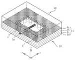
도 1은 본 발명의 제1 실시 예에 따른 매칭 기판을 이용한 유전체 공진기 안테나의 사시도이다.
도 2는 도 1의 매칭 기판을 이용한 유전체 공진기 안테나의 평면도이다.
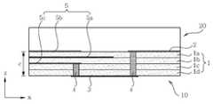
도 3은 도 2에 표시된 A-A'선을 따라 절단된 도 1의 매칭 기판을 이용한 유전체 공진기 안테나의 단면도이다.
도 4는 도 2에 표시된 B-B'선을 따라 절단된 도 1의매칭 기판을 이용한 유전체 공진기 안테나의 단면도이다.
도 5는 본 발명에 따른 매칭 기판의 역할을 해석하기 위한 전송선 등가 회로도이다.
도 6은 본 발명의 일 실시 예에서 매칭 기판 유무에 따른 안테나 특성 변화를 나타내는 시뮬레이션 그래프이다.
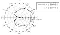
도 7은 본 발명의 일 실시 예에서 매칭 기판 유무에 따라 -10dB 매칭 주파수에서의 E-평면(E-plane) 방사 패턴을 나타내는 도면이다.
도 8은 본 발명의 제2 실시 예에 따른 매칭 기판을 이용한 유전체 공진기 안테나의 사시도이다.
도 9는 도 8의 매칭 기판을 이용한 유전체 공진기 안테나의 평면도이다.
도 10은 도 9에 표시된 C-C'선을 따라 절단된 도 8의 매칭 기판을 이용한 유전체 공진기 안테나의 단면도이다.
도 11은 도 9에 표시된 D-D'선을 따라 절단된 도 8의 매칭 기판을 이용한 유전체 공진기 안테나의 단면도이다.
도 12는 본 발명의 일 실시 예에서 매칭 기판에 형성된 다수의 매칭 기판 비아홀 유무에 따른 안테나 특성 변화를 나타내는 시뮬레이션 그래프이다.
도 13은 본 발명의 일 실시 예에서 매칭 기판에 형성된 다수의 매칭 기판 비아홀 유무에 따라 -10dB 매칭 주파수에서의 E-평면(E-plane) 방사 패턴을 나타내는 도면이다.
도 14는 본 발명의 제3 실시 예에 따른 매칭 기판을 이용한 유전체 공진기 안테나의 사시도이다.
도 15는 도 14의 매칭 기판을 이용한 유전체 공진기 안테나의 평면도이다.
도 16은 도 15에 표시된 E-E'선을 따라 절단된 도 14의 매칭 기판을 이용한 유전체 공진기 안테나의 단면도이다.
도 17은 도 15에 표시된 F-F'선을 따라 절단된 도 14의 매칭 기판을 이용한 유전체 공진기 안테나의 단면도이다.
도 18은 본 발명의 제4 실시 예에 따른 매칭 기판을 이용한 유전체 공진기 안테나의 사시도이다.
도 19는 도 18의 매칭 기판을 이용한 유전체 공진기 안테나의 평면도이다.
도 20은 도 19에 표시된 G-G'선을 따라 절단된 도 18의 매칭 기판을 이용한 유전체 공진기 안테나의 단면도이다.
도 21은 도 19에 표시된 H-H'선을 따라 절단된 도 18의 매칭 기판을 이용한 유전체 공진기 안테나의 단면도이다.1 is a perspective view of a dielectric resonator antenna using a matching substrate according to a first embodiment of the present invention.
FIG. 2 is a plan view of a dielectric resonator antenna using the matching substrate of FIG. 1.
3 is a cross-sectional view of the dielectric resonator antenna using the matching substrate of FIG. 1 cut along the line AA ′ shown in FIG. 2.
4 is a cross-sectional view of the dielectric resonator antenna using the matching substrate of FIG. 1 cut along the line BB ′ shown in FIG. 2.
5 is a transmission line equivalent circuit diagram for analyzing the role of the matching substrate according to the present invention.
6 is a simulation graph illustrating a change in antenna characteristics depending on whether a matching substrate is present in an embodiment of the present invention.
FIG. 7 is a diagram illustrating an E-plane radiation pattern at -10 dB matching frequency according to the presence or absence of a matching substrate in an embodiment of the present invention.
8 is a perspective view of a dielectric resonator antenna using a matching substrate according to the second embodiment of the present invention.
9 is a plan view of a dielectric resonator antenna using the matching substrate of FIG. 8.
FIG. 10 is a cross-sectional view of the dielectric resonator antenna using the matching substrate of FIG. 8 cut along the line CC ′ shown in FIG. 9.
FIG. 11 is a cross-sectional view of the dielectric resonator antenna using the matching substrate of FIG. 8 cut along the line D-D ′ shown in FIG. 9.
FIG. 12 is a simulation graph illustrating a change in antenna characteristics depending on whether a plurality of matching substrate via holes are formed on a matching substrate in an embodiment of the present invention.
FIG. 13 is a diagram illustrating an E-plane radiation pattern at a -10 dB matching frequency according to whether a plurality of matching substrate via holes are formed in a matching substrate in an embodiment of the present invention.
14 is a perspective view of a dielectric resonator antenna using a matching substrate according to the third embodiment of the present invention.
FIG. 15 is a plan view of a dielectric resonator antenna using the matching substrate of FIG. 14.
FIG. 16 is a cross-sectional view of the dielectric resonator antenna using the matching substrate of FIG. 14 cut along the line E-E 'shown in FIG.
FIG. 17 is a cross-sectional view of the dielectric resonator antenna using the matching substrate of FIG. 14 cut along the line FF ′ shown in FIG. 15.
18 is a perspective view of a dielectric resonator antenna using a matching substrate according to the fourth embodiment of the present invention.
FIG. 19 is a plan view of a dielectric resonator antenna using the matching substrate of FIG. 18.
20 is a cross-sectional view of the dielectric resonator antenna using the matching substrate of FIG. 18 cut along the line G-G 'shown in FIG.
FIG. 21 is a cross-sectional view of the dielectric resonator antenna using the matching substrate of FIG. 18 cut along the line H-H 'shown in FIG.
이하, 첨부된 도면을 참조하여 본 발명의 바람직한 실시 예들을 상세히 설명하기로 한다.Hereinafter, exemplary embodiments of the present invention will be described in detail with reference to the accompanying drawings.
설명의 용이함을 위하여 본 발명의 다층 기판은 4층의 절연층이 적층된 기판을 사용하였으나, 이에 한정되는 것은 아니다.For ease of description, the multilayer substrate of the present invention uses a substrate in which four insulating layers are stacked, but is not limited thereto.
또한, 본 발명의 도면에서, 급전부를 위한 도체층 이외의 도체층은 생략된 것으로 간주하여 도시하지 않았음을 일러둔다.It should be noted that, in the drawings of the present invention, conductor layers other than the conductor layer for the power supply unit are not shown as considered omitted.
도 1은 본 발명의 제1 실시 예에 따른 매칭 기판을 이용한 유전체 공진기 안테나의 사시도이고, 도 2는 도 1의 매칭 기판을 이용한 유전체 공진기 안테나의 평면도이며, 도 3은 도 2에 표시된 A-A'선을 따라 절단된 도 1의 매칭 기판을 이용한 유전체 공진기 안테나의 단면도이며, 도 4는 도 2에 표시된 B-B'선을 따라 절단된 도 1의 매칭 기판을 이용한 유전체 공진기 안테나의 단면도이다.1 is a perspective view of a dielectric resonator antenna using a matching substrate according to a first embodiment of the present invention, FIG. 2 is a plan view of the dielectric resonator antenna using the matching substrate of FIG. 1, and FIG. 3 is A-A shown in FIG. 2. 1 is a cross-sectional view of the dielectric resonator antenna using the matching substrate of FIG. 1 cut along a line, and FIG. 4 is a cross-sectional view of the dielectric resonator antenna using the matching substrate of FIG. 1 cut along the line B-B shown in FIG.
도 1 내지 4를 참조하면, 본 발명의 제1 실시 예에 따른 매칭 기판을 이용한 유전체 공진기 안테나는, 다층 기판(1)에 내장되며, 상단에 개구부를 갖는 유전체 공진기 본체부(10) 및 상기 개구부 위에 적층되며, 적어도 하나 이상의 절연층이 적층된 매칭 기판(20)을 포함하여 이루어진다.1 to 4, the dielectric resonator antenna using the matching substrate according to the first embodiment of the present invention is embedded in the
본 발명에서는 설명의 용이함을 위하여 하나의 매칭 기판(20)만을 도시하고 설명하였으나, 둘 이상의 매칭 기판이 적층될 수도 있다. 이 경우, 적층된 매칭 기판의 유전율이 단계적으로 감소되도록 적층되는 것이 바람직하다.In the present invention, only one matching
또한, 상기 매층 기판(20)의 유전율(ε2)은 상기 다층 기판(1)의 유전율(ε1)보다 작고 공기의 유전율(ε0)보다 큰 것이 바람직하다.In addition, the dielectric constant ε2 of the buried
상기 유전체 공진기 본체부(10)는 다층 기판(1), 상기 다층 기판(1)의 최상위 절연층(1a) 상단에 개구부를 갖는 제1 도체판(2), 상기 다층 기판(1)의 최하위 절연층(1d)의 하단에 위치한 제2 도체판(3), 상기 최상위 절연층(1a)과 상기 최하위 절연층(1d) 사이를 관통하는 다수의 제1 금속 비아홀(4), 및 급전 라인(5a)과 적어도 하나 이상의 접지판(5b, 5c)으로 구성된 급전부(5)를 포함한다.The dielectric
상기 다층 기판(1)은 다수의 절연층(1a~1d)과 다수의 도체층(예컨대, 2,3,5a, 5c)이 교대로 적층되어 형성됨으로써, 상기 다층 기판(1) 내에 유전체 공진기를 내장할 수 있다.The
종래 유전체 공진기 본체부에서는 단일 기판 위에 직육면체 또는 원통형으로 형성된 유전체 안테나와 공기 사이의 유전율 차이에 의해 경계면이 자벽(Magnetic Wall)과 같이 작용하여 특정 주파수의 공진모드를 형성한다.In the conventional dielectric resonator main body, the interface acts like a magnetic wall due to the difference in dielectric constant between air and a dielectric antenna formed in a rectangular parallelepiped or cylindrical shape on a single substrate to form a resonance mode of a specific frequency.
반면에, 본 발명에서와 같이 다층 기판(1) 내부에 유전체 공진기를 내장할 시에는 상기 다층 기판(1)의 수직 방향의 금속 경계면과 상기 다층 기판(1)의 최하위 절연층 하단에 형성된 도체판에 의해 형성된 금속 경계면 및 상기 최상위 절연층 상단에 형성된 개구면의 자벽을 사용해 공진 모드를 유지시켜 준다.On the other hand, when the dielectric resonator is embedded in the
이때, 이상적인 경우에는 다층 구조에서 기판의 수직방향 금속 경계면이 요구되지만, 제작상의 어려움 때문에 일정한 간격으로 배열된 다수의 금속 비아를 사용해 이를 대체할 수 있다.In this case, a vertical metal interface of the substrate is required in a multilayer structure, but due to manufacturing difficulties, it may be replaced by using a plurality of metal vias arranged at regular intervals.
따라서, 상기 다층 기판(1)에 유전체 공진기를 내장하기 위하여, 최상위 절연층(1a)의 상단에 개구부를 갖는 제1 도체판(2)이 형성되어 있다.Therefore, in order to embed the dielectric resonator in the
그리고, 상기 제1 도체판(2)으로부터 적어도 2층 이상이 적층된 최하위 절연층(1d)의 하단에 상기 개구부에 대응되는 위치의 제2 도체판(3)이 형성되어 있다.And the
또한, 상기 최상위 절연층(1a)과 상기 최하위 절연층(1d) 사이의 각 층간을 전기적으로 접속하고 상기 제1 도체판(2)의 상기 개구부 주위를 소정 간격으로 둘러싸 수직 방향의 금속 경계면을 형성하도록 상기 다층 기판(1)을 수직으로 관통하는 다수의 제1 금속 비아홀(4)이 형성되어 있다.In addition, the interlayer between the uppermost insulating layer 1a and the lowermost insulating
이로써, 상기 제1 도체판(2), 상기 제2 도체판(3) 및 상기 다수의 제1 금속 비아홀(4)에 의해 형성된 금속 경계면에 의해 한 면(이를 테면, 상기 제1 도체판(2)의 개구부가 형성된 면) 만이 개방된 유전체 공진기가 상기 다층 기판(1) 내에 캐비티(cavity) 형태로 내장되게 되는 것이다.As a result, one surface (for example, the first conductor plate 2) is formed by a metal interface formed by the
상기 급전부(5)는 상기 다층 기판(1)에 캐비티 형태로 내장된 유전체 공진기에 급전하기 위해 상기 유전체 공진기의 일 측에 형성된다.The
이러한 상기 급전부(5)는 상기 다층 기판(1)에 용이하게 형성될 수 있는 스트립 라인, 마이크로 스트립 라인 및 CPW(coplanar waveguide) 라인과 같은 전송 선로(이하 '급전 라인'이라 칭함)를 이용하여 급전할 수 있도록 구현된다.The
이러한 상기 급전부(5)는 하나의 급전 라인(5a)과 적어도 하나 이상의 접지판(5b, 5c)으로 구성된다.The feeding
도 1 내지 4에 도시된 상기 유전체 공진기 본체부(10)의 급전부(5)는 스트립 라인 구조로 되어 있다.The
보다 구체적으로, 상기 스트립 라인 구조의 급전부(5)는, 급전 라인(5a), 제1 접지판(5b) 및 제2 접지판(5c)으로 구성된다.More specifically, the
상기 급전 라인(5a)은 상기 유전체 공진기 본체부(10)의 개구부와 수평되게 상기 유전체 공진기의 일측면으로부터 상기 유전체 공진기의 내부로 삽입되도록 연장된 라인 형태의 도체판으로 형성된다.The
상기 제1 접지판(5b)은 상기 급전 라인(5a)과 대응되도록 위치되며 상기 급전 라인(5a)으로부터 위로 적어도 1층 이상 적층된 절연층(1a) 상단에 형성된다.The
상기 제2 접지판(5c)은 상기 급전 라인(5a)과 대응되도록 위치되며 상기 급전 라인(5a)으로부터 아래로 적어도 1층 이상 적층된 절연층(1b) 하단에 형성된다.The
상술한 상기 제1 및 제2 접지판(5b 및 5c)은 상기 급전 라인(5a)과 반드시 대응되는 위치에 형성되어야 하며, 그 크기와 형태에 제한은 없다.The first and
여기서, 상기 제1 접지판(5b)은 상기 제1 도체판(2)과 일체로 형성될 수도 있다.Here, the
상술한 바와 같은 상기 다층 기판(1)에 내장된 유전체 공진기 본체부(10)는 급전부(5)의 급전 라인(5a)을 통해 고주파 신호가 인가되며, 상기 유전체 공진기의 형태 및 크기에 따라 특정 주파수에서 공진하는 고주파 신호를 상기 개구부를 통해 방사하는 안테나 방사체로서 기능하게 된다.As described above, the
상기 매칭 기판(20)은 상술한 바와 같이 상기 유전체 공진기 본체부(10)의 개구부 위에 적층된다.The matching
이러한 매칭 기판(20)은 고유전율(ε1)의 다층 기판(1)에 내장된 상기 유전체 공진기 본체부(10)와 저유전율(ε0)의 공기와의 경계면에서 발생되는 반사파를 제거하여 대역폭을 향상시킬 수 있다.The matching
일반적으로, 상기 반사파가 발생되는 원인은 상기 유전체 공진기 본체부(10)의 시스템 임피던스(Z1)와 상기 개구부의 방사저항(Zant)의 미스매치(mismatch)에 있다.In general, the cause of the reflected wave is a mismatch between the system impedance Z1 of the
따라서, 상기 유전체 공진기 본체부(10)의 개구부 위에 매칭 기판(20)을 적층함으로써 상기 매칭 기판(20)이 90도 트랜스포머(90 degree transformer)와 유사한 역할을 하여 상기 유전체 공진기 본체부(10)와 공기와의 임피던스 매칭이 가능해진다.Accordingly, by stacking the matching
도 5는 본 발명에 따른 매칭 기판의 역할을 해석하기 위한 전송선 등가회로도이다.5 is a transmission line equivalent circuit diagram for analyzing the role of the matching substrate according to the present invention.
도 5를 참조하면, 상기 유전체 공진기 본체부(10)의 시스템 임피던스를 Z1, 공기의 등가 임피던스를 Z0, 상기 유전체 공진기 본체부(10)와 공기와의 경계면에 위치된 매칭 기판(20)의 임피던스를 Z2이라 하면, 상기 유전체 공진기 본체부(10) 측에서 바라본 입력 임피던스(Zin)는 하기 식(1)과 같다:Referring to FIG. 5, the system impedance of the dielectric resonator

상기 유전체 공진기 본체부(10)의 시스템 임피던스(Z1)와 공기의 등가 임피던스(Z0)의 미스매치를 줄이기 위해 쿼터-웨이브 매칭(quarter-wave matching) 이론을 이용한다.Quarter-wave matching theory is used to reduce the mismatch between the system impedance Z1 of the
여기서, 상기 쿼터-웨이브 매칭은 90도 라인을 이용한 것으로 가정하고, 이 경우 상기 식(1)에 대입하면 다음과 같이 하기 식(2)로 변형된다:Here, the quarter-wave matching is assumed to use a 90-degree line, in which case the equation (1) is substituted into the following equation (2):

여기서, 상기 유전체 공진기 본체부(10)의 시스템 임피던스(Z1)와 공기의 등가 임피던스(Z0)의 미스매치를 줄이기 위해서는, 하기 식(3)과 같이, 상기 유전체 공진기 본체부(10) 측에서 바라본 입력 임피던스(Zin)가 상기 유전체 공진기 본체부(10)의 시스템 임피던스(Z1)와 같게 되도록 상기 매칭 기판(20)을 삽입하면 된다:Here, in order to reduce the mismatch between the system impedance Z1 of the dielectric resonator
Zin=Z1 (3)Zin= ZOne(3)
따라서, 상기 매칭 기판(20)의 시스템 임피던스(Z2) 값은 식(3)을 식 (2)에 대입하여 구할 수 있다:Therefore, the system impedance Z2 value of the matching

한편, 시스템 임피던스(Z)를 유전율(ε)과 투자율(μ)로 표현하면 일반적으로 다음과 같이 나타낼 수 있다:On the other hand, if the system impedance (Z) is expressed as permittivity (ε) and permeability (μ), it can be generally expressed as:

식 (4) 및 (5)를 이용하면, 상기 매칭 기판(20)의 유전율(ε2) 값은 다음과 같이 나타낼 수 있다:Using equations (4) and (5), the value of permittivity ε2 of the matching
(6)
(6)
여기서, ε1은 상기 유전체 공진기 본체부(10)의 다층 기판(1)의 유전율이고, ε0는 공기의 유전율이다.Here, epsilon1 is the dielectric constant of the multilayer substrate1 of the
도 6은 본 발명의 일 실시 예에서 매칭 기판 유무에 따른 안테나 특성 변화를 나타내는 시뮬레이션 그래프이고, 도 7은 본 발명의 일 실시 예에서 매칭 기판 유무에 따라 -10dB 매칭 주파수에서의 E-평면(E-plane) 방사 패턴을 나타내는 도면이다.FIG. 6 is a simulation graph illustrating a change in antenna characteristics according to the presence or absence of a matching substrate in an embodiment of the present invention. FIG. 7 is an E-plane (E) at a -10 dB matching frequency according to the presence or absence of a matching substrate in an embodiment of the present invention. -plane) A diagram showing a radiation pattern.
도 6을 참조하면, 매칭 기판(20)이 없을 경우 소정의 대역폭을 갖는 안테나로 동작하는 것으로 볼 수 없으나, 매칭 기판(20)이 있을 경우 -10dB 매칭 주파수 지점을 기준으로 약 60GHz 전후(a 대역)의 대역폭에서 동작하는 안테나 특성을 보여주고 있다.Referring to FIG. 6, when there is no matching
또한, 도 7을 참조하면, 매칭 기판(20)의 유무에 따라 90도에서의 이득값[dB]을 비교해 보면, 매칭 기판(20)이 없을 경우 약 2.84dB이고 매칭 기판(20)이 있을 경우 약 3.84dB로 더 높은 것을 알 수 있다.In addition, referring to FIG. 7, when comparing the gain value [dB] at 90 degrees according to the presence or absence of the matching
도 6과 7에 도시된 바와 같이, 상기 유전체 공진기 본체부(10)의 크기를 조정하지 않고도 상기 유전체 공진기 본체부(10)의 개구부 위에 상기 매칭 기판(20)을 적층함으로써 대역폭을 향상시킬 수 있음을 알 수 있다.As shown in FIGS. 6 and 7, the bandwidth can be improved by stacking the matching
한편, 최대 대역폭을 얻기 위해 상기 매칭 기판(20)의 유전율 및 두께가 증가할 수 있는데, 이로 인한 방사 에너지 손실 및 방사 패턴의 변화를 방지할 수 있는 방법은 아래에 설명한다.On the other hand, the dielectric constant and thickness of the matching
도 8은 본 발명의 제2 실시 예에 따른 매칭 기판을 이용한 유전체 공진기 안테나의 사시도이고, 도 9는 도 8의 매칭 기판을 이용한 유전체 공진기 안테나의 평면도이며, 도 10은 도 9에 표시된 C-C'선을 따라 절단된 도 8의 매칭 기판을 이용한 유전체 공진기 안테나의 단면도이며, 도 11은 도 9에 표시된 D-D'선을 따라 절단된 도 8의 매칭 기판을 이용한 유전체 공진기 안테나의 단면도이다.8 is a perspective view of a dielectric resonator antenna using a matching substrate according to a second embodiment of the present invention, FIG. 9 is a plan view of the dielectric resonator antenna using the matching substrate of FIG. 8, and FIG. 10 is a C-C shown in FIG. 9. 8 is a cross-sectional view of the dielectric resonator antenna using the matching substrate of FIG. 8 cut along a line, and FIG. 11 is a cross-sectional view of the dielectric resonator antenna using the matching substrate of FIG. 8 cut along the line D-D shown in FIG.
도 8 내지 11을 참조하면, 본 발명의 제2 실시 예에 따른 매칭 기판을 이용한 유전체 공진기 안테나는 다층 기판(1)에 내장된 유전체 공진기 본체부(10) 및 상기 유전체 공진기 본체부(10) 상단에 적층된 매칭 기판(20)을 포함하여 이루어진다.8 to 11, a dielectric resonator antenna using a matching substrate according to a second embodiment of the present invention includes a dielectric
여기서, 상기 유전체 공진기 본체부(10)는 본 발명의 제1 실시 예에서와 동일한 유전체 공진기 본체부(10)가 사용되므로, 이에 대한 상세 설명은 상술한 것으로 대체하기로 한다.Here, since the dielectric
본 발명의 제2 실시 예에 따른 매칭 기판을 이용한 유전체 공진기 안테나에 사용된 상기 매칭 기판(20)에는 상기 유전체 공진기 본체부(10)의 개구부 주위를 둘러싸 수직 금속 경계면을 형성하도록 다수의 매칭 기판 비아홀(20a)이 형성되어 있다.In the matching
상기 매칭 기판(20)에 상기 다수의 매칭 기판 비아홀(20a)을 형성함으로써, 상기 매칭 기판(20)의 유전율과 두께가 증가할 경우 발생되는 기판 모드(substrate mode)에 의한 손실(상기 유전체 공진기 본체부(10)의 개구부로부터 방사되는 에너지가 매칭 기판(20)의 측상으로 방사됨으로써 발생되는 에너지 손실) 및 방사패턴의 변화 등을 개선할 수 있다.By forming the plurality of matching substrate via
도 12는 본 발명의 일 실시 예에서 매칭 기판에 형성된 다수의 매칭 기판 비아홀 유무에 따른 안테나 특성 변화를 나타내는 시뮬레이션 그래프이고, 도 13은 본 발명의 일 실시 예에서 매칭 기판에 형성된 다수의 매칭 기판 비아홀 유무에 따라 -10dB 매칭 주파수에서의 E-평면(E-plane) 방사 패턴을 나타내는 도면이다.12 is a simulation graph illustrating a change in antenna characteristics depending on whether a plurality of matching substrate via holes are formed in a matching substrate in an embodiment of the present invention, and FIG. 13 is a plurality of matching substrate via holes formed in a matching substrate in an embodiment of the present invention. A diagram showing an E-plane radiation pattern at -10 dB matching frequency with and without.
도 12를 참조하면, 상기 매칭 기판(20)에 매칭 기판 비아홀(20a)이 형성되어 있을 경우(b 대역) -10dB 매칭 주파수 지점을 기준으로 매칭 기판 비아홀(20a)이 없을 경우(c 대역)보다 대역폭은 다소 줄어들었음을 알 수 있다.Referring to FIG. 12, when the matching substrate via
그러나, 도 13에 도시된 방사 패턴을 참조하여 90도에서의 이득값[dB]을 비교해 보면, 매칭 기판(20)에 다수의 매칭 기판 비아홀(20a)이 없는 경우 이득값[dB]은 약 3.84dB인 것에 반해, 매칭 기판(20)에 다수의 매칭 기판 비아홀(20a)이 있는 경우 이득값[dB]은 약 7.44dB로 크게 향상되었음을 알 수 있다.However, when comparing the gain value [dB] at 90 degrees with reference to the radiation pattern shown in FIG. 13, the gain value [dB] is about 3.84 when the matching
이러한 상기 다수의 매칭 기판 비아홀(20a)은 금속 비아홀뿐만 아니라 공기 비아홀로도 대체 가능하다.The plurality of matching substrate via
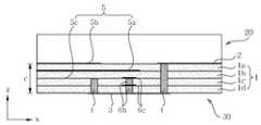
도 14는 본 발명의 제3 실시 예에 따른 매칭 기판을 이용한 유전체 공진기 안테나의 사시도이고, 도 15는 도 14의 매칭 기판을 이용한 유전체 공진기 안테나의 평면도이며, 도 16은 도 15에 표시된 E-E'선을 따라 절단된 도 14의 매칭 기판을 이용한 유전체 공진기 안테나의 단면도이며, 도 17은 도 15에 표시된 F-F'선을 따라 절단된 도 14의 매칭 기판을 이용한 유전체 공진기 안테나의 단면도이다.14 is a perspective view of a dielectric resonator antenna using a matching substrate according to a third embodiment of the present invention, FIG. 15 is a plan view of the dielectric resonator antenna using the matching substrate of FIG. 14, and FIG. 16 is an E-E shown in FIG. 15. 14 is a cross-sectional view of the dielectric resonator antenna using the matching substrate of FIG. 14 cut along a line, and FIG. 17 is a cross-sectional view of the dielectric resonator antenna using the matching substrate of FIG. 14 cut along the line F-F shown in FIG.
도 14 내지 17을 참조하면, 본 발명의 제3 실시 예에 따른 매칭 기판을 이용한 유전체 공진기 안테나는 다층 기판(1)에 내장된 유전체 공진기 본체부(30) 및 상기 유전체 공진기 본체부(30) 상단에 적층된 매칭 기판(20)을 포함하여 이루어진다.14 to 17, a dielectric resonator antenna using a matching substrate according to a third exemplary embodiment of the present invention includes a dielectric
상기 유전체 공진기 본체부(30)는 다층 기판(1), 상기 다층 기판(1)의 최상위 절연층(1a) 상단에 개구부를 갖는 제1 도체판(2), 상기 다층 기판(1)의 최하위 절연층(1d)의 하단에 위치한 제2 도체판(3), 상기 최상위 절연층(1a)과 상기 최하위 절연층(1d) 사이를 관통하는 다수의 제1 금속 비아홀(4), 급전 라인(5a)과 적어도 하나 이상의 접지판(5b, 5c)으로 구성된 급전부(5) 및 상기 유전체 공진기 안테나 내부에 삽입된 도체 패턴부(6)를 포함하여 이루어진다.The dielectric resonator
이러한 상기 유전체 공진기 본체부(30)는 본 발명의 제1 및 제2 실시 예에서 사용된 유전체 공진기 본체부(10)에서 상기 도체 패턴부(6)를 제외하면, 동일한 구조이므로 동일 구성요소에 대한 상세 설명은 상술한 것으로 대체하기로 한다.The dielectric
상기 도체 패턴부(6)는 상기 유전체 공진기 본체부(30)가 (예컨대, 기본 모드(TE101)와 추가 모드(TM111)에 의한) 이중 공진으로 동작할 경우, 추가 모드(TM111)를 제거하여 안테나의 방사 특성을 좋게 하기 위해 상기 유전체 공진 안테나 내부에 삽입된다.The
상기 도체 패턴부(6)가 상기 유전체 공진기 내부에 삽입되면, 이중 공진 (TE101+ TM111) 시 상기 유전체 공진기 내부에 형성된 전계(E-field) 의 접선 전계(Tangential field)를 제거하고 법선 전계(Normal field)를 유지시켜 효과적으로 추가 모드(TM111)를 제거할 수 있다.When the
이러한 상기 도체 패턴부(6)는 상기 유전체 공진기 안테나가 이중 공진 시 상기 유전체 공진기 중앙에 강한 전계(E-field)를 가지므로 급전 라인(5a)과 평행한 방향인 x방향 길이(a)의 중심(a/2)에 위치하는 것이 가장 바람직하다.The
구체적으로, 도 16 및 17을 참조하면, 상기 도체 패턴부(6)는 상기 유전체 공진기 내부에 상기 급전 라인(5a)과 교차되는 수직방향의 금속 경계면을 형성하도록 급전 라인(5a)으로부터 아래로 적어도 1층 이상 적층된 절연층 아래에 형성된다.Specifically, referring to FIGS. 16 and 17, the
이러한 상기 도체 패턴부(6)는 상기 유전체 공진기 내부에 다층 기판(1)을 수직으로 관통하는 다수의 제2 금속 비아홀(6b)과, 상기 다수의 제2금속 비아홀(6b)이 관통되는 절연층(1a~1d) 사이에 상기 다수의 제2 금속 비아홀(6a)과 결합되도록 형성된 적어도 하나 이상의 제3 도체판(6a, 6c)으로 이루어진다.The
상기 도체 패턴부(6)는 상기 다수의 제2 금속 비아홀(6b)과 상기 적어도 하나 이상의 제3 도체판(6a, 6c)에 의해, 도 17에 도시된 바와 같은 그물 형태의 도체 패턴으로 상기 유전체 공진기 내부에 상기 급전 라인(5a)과 교차되는 수직방향의 금속 경계면을 형성할 수 있게 된다.The
도 17을 참조하면, 상기 다수의 제2 금속 비아홀(6b)은 상기 급전 라인(5a)을 중심으로 상기 급전 라인(5a)으로부터 아래로 적어도 1층 이상 적층된 절연층 아래에 형성되어야 한다.Referring to FIG. 17, the plurality of second metal via
또한, 상기 다수의 제2 금속 비아홀(6b)은 상기 급전 라인(5a)을 중심으로 좌우로는 모든 절연층에 형성될 수 있다.In addition, the plurality of second metal via
다만, 상기 다수의 제2 금속 비아홀(6b)은 상기 급전 라인(5a)으로부터 개구부까지 상기 급전 라인(5a) 바로 위의 모든 절연층에는 형성되어서는 안 된다.However, the plurality of second metal via
도 17에서는 상기 도체 패턴부(6)가 전체적으로 말굽 형태로 도시되었으나, 이에 한정되지 않으며 사각 형태를 포함한 여러 가지 형태로 형성될 수도 있다.In FIG. 17, the
본 발명의 제3 실시 예에 따른 매칭 기판을 이용한 유전체 공진기 안테나에 사용된 상기 매칭 기판(20)은 본 발명의 제1 실시 예에 따른 매칭 기판을 이용한 유전체 공진기 안테나에 사용된 매칭 기판(20)과 동일하므로 이에 대한 상세 설명은 상술한 것으로 대체하기로 한다.The matching
마지막으로, 본 발명의 제3 실시 예에 따른 매칭 기판을 이용한 유전체 공진기 안테나에서 사용된 상기 매칭 기판(20)에 본 발명의 제2 실시 예에 따른 매칭 기판을 이용한 유전체 공진기 안테나에 사용된 것과 동일한 다수의 매칭 기판 비아홀(20a)이 형성된 제4 실시 예가 도 18 내지 21에 도시된다.Finally, the matching
도 18은 본 발명의 제4 실시 예에 따른 매칭 기판을 이용한 유전체 공진기 안테나의 사시도이고, 도 19는 도 18의 매칭 기판을 이용한 유전체 공진기 안테나의 평면도이며, 도 20은 도 19에 표시된 G-G'선을 따라 절단된 도 18의 매칭 기판을 이용한 유전체 공진기 안테나의 단면도이며, 도 21은 도 19에 표시된 H-H'선을 따라 절단된 도 18의 매칭 기판을 이용한 유전체 공진기 안테나의 단면도이다.18 is a perspective view of a dielectric resonator antenna using a matching substrate according to a fourth embodiment of the present invention, FIG. 19 is a plan view of the dielectric resonator antenna using the matching substrate of FIG. 18, and FIG. 20 is a G-G shown in FIG. 19. 18 is a cross-sectional view of the dielectric resonator antenna using the matching substrate of FIG. 18 cut along a line, and FIG. 21 is a cross-sectional view of the dielectric resonator antenna using the matching substrate of FIG. 18 cut along the line H-H shown in FIG.
도 18 내지 21을 참조하면, 본 발명의 제4 실시 예에 따른 매칭 기판을 이용한 유전체 공진기 안테나는 다층 기판(1)에 내장된 유전체 공진기 본체부(30) 및 상기 유전체 공진기 본체부(30) 상단에 적층된 매칭 기판(20)을 포함하여 이루어진다.18 to 21, a dielectric resonator antenna using a matching substrate according to a fourth exemplary embodiment of the present invention includes a dielectric
상기 유전체 공진기 본체부(30)는 본 발명의 제3 실시 예에 사용된 것과 동일하고, 상기 매칭 기판(20)은 본 발명의 제2 실시 예에 사용된 것과 동일하므로 이에 대한 상세 설명은 상술한 것으로 대체하기로 한다.The dielectric
상술한 바와 같은 본 발명의 제1 내지 제4 실시 예에 따른 매칭 기판을 이용한 유전체 공진기 안테나는 다층 기판(1)에 내장된 유전체 공진기 본체부(10, 30)의 개구부 위에 매칭 기판(20)을 적층함으로써, 상기 유전체 공진기 본체부(10, 30)의 크기 조정 없이도 대역폭을 향상시킬 수 있으며 공정 또한 간단하다.As described above, the dielectric resonator antenna using the matching substrates according to the first to fourth embodiments of the present invention uses the matching
또한, 상기 유전체 공진기 본체부(10, 30) 위에 적층된 매칭 기판(20)은 상기 개구부를 통해 상기 유전체 공진기 본체부(10, 30)에 이물질이 삽입되거나 안테나 표면 손상으로 인한 안테나 특성 변화를 방지하는 역할을 한다.In addition, the matching
또한, 상기 매칭 기판(20)에 다수의 매칭 기판 비아홀(20a)을 형성함으로써, 최대 대역폭을 얻기 위해 상기 매칭 기판(20)의 두께가 증가할 경우 발생되는 기판 모드에 의한 손실 및 방사패턴 변화를 방지할 수 있다.In addition, by forming a plurality of matching substrate via
상기에서는 본 발명의 바람직한 실시 예를 참조하여 설명하였지만, 해당 기술 분야에서 통상의 지식을 가진 자라면 하기의 특허 청구의 범위에 기재된 본 발명의 사상 및 영역으로부터 벗어나지 않는 범위 내에서 본 발명을 다양하게 수정 및 변경시킬 수 있음을 이해할 수 있을 것이다.
Although the above has been described with reference to a preferred embodiment of the present invention, those skilled in the art to which the present invention pertains without departing from the spirit and scope of the present invention as set forth in the claims below It will be appreciated that modifications and variations can be made.
1: 다층 기판2: 제1 도체판
3: 제2 도체판4: 제1 금속 비아홀
5a: 급전 라인5b: 제1 접지판
5c: 제2 접지판6: 도체 패턴부
6a, 6c: 제 3 도체판6b: 제 2 금속 비아홀
10, 30: 유전체 공진기 본체부20: 매칭 기판
20a: 매칭 기판 비아홀1: Multilayer Substrate 2: First Conductor Plate
3: second conductor plate 4: first metal via hole
5a: feed
5c: second ground plate 6: conductor pattern portion
6a, 6c:
10, 30: dielectric resonator body portion 20: matching substrate
20a: Matching substrate via hole
Claims (10)
Translated fromKorean상기 개구부 위에 적층되며 적어도 하나 이상의 절연층이 적층된 매칭 기판을 포함하며,
상기 유전체 공진기 본체부는,
다수의 절연층과 도체층이 교대로 적층되어 형성된 다층 기판;
상기 다층 기판의 최상위 절연층의 상단에 개구부를 갖는 제1 도체판;
상기 제1 도체판으로부터 적어도 2층 이상이 적층된 절연층 중 최하위 절연층의 하단에 형성되며 상기 개구부에 대응되는 위치의 제2 도체판;
상기 최상위 절연층과 상기 최하위 절연층 사이의 각 층간을 전기적으로 접속하고, 상기 제1 도체판의 상기 개구부 주위를 소정 간격으로 둘러싸 수직 방향의 금속 경계면이 형성되도록 상기 다층 기판을 수직으로 관통하는 다수의 제1 금속 비아홀;
상기 제1 도체판, 상기 제2 도체판, 및 상기 다수의 제1 금속 비아홀에 의한 금속 경계면에 의해 상기 다층 기판 내에 캐비티 형태로 내장된 유전체 공진기에 고주파 신호를 인가하기 위한 급전 라인을 포함하는 급전부; 및
상기 유전체 공진기 내부에 상기 급전 라인과 교차되는 수직 방향의 금속 경계면이 형성되도록 삽입된 도체 패턴부를 포함하는 것을 특징으로 하는 매칭 기판을 이용한 유전체 공진기 안테나.
A dielectric resonator body part embedded in a multilayer substrate and having an opening at an upper end thereof; And
A matching substrate stacked on the opening and having at least one insulating layer stacked thereon;
The dielectric resonator body portion,
A multilayer substrate formed by alternately stacking a plurality of insulating layers and conductor layers;
A first conductor plate having an opening at an upper end of an uppermost insulating layer of the multilayer substrate;
A second conductor plate formed at a lower end of a lowermost insulating layer among at least two insulating layers laminated from the first conductor plate and corresponding to the opening;
A plurality of vertically penetrating the multilayer substrate so as to electrically connect the respective layers between the uppermost insulating layer and the lowermost insulating layer and surround the opening of the first conductor plate at predetermined intervals so that a metal boundary in a vertical direction is formed. A first metal via hole;
A feed line including a feed line for applying a high frequency signal to a dielectric resonator embedded in a cavity in the multilayer substrate by the metal boundary surface of the first conductor plate, the second conductor plate, and the plurality of first metal via holes; all; And
And a conductor pattern portion inserted into the dielectric resonator so as to form a metal boundary surface in a vertical direction crossing the feed line.
상기 유전체 공진기 내부에 다층 기판을 수직으로 관통하는 다수의 제2 금속 비아홀; 및
상기 다수의 제2 금속 비아홀이 관통되는 절연층 사이에 상기 다수의 제2 금속 비아홀과 결합되도록 형성된 적어도 하나 이상의 제3 도체판을 포함하는 것을 특징으로 하는 대역폭 향상을 위한 다층 기판에 내장된 유전체 공진기 안테나.The method according to claim 1, The conductor pattern portion,
A plurality of second metal via holes vertically penetrating the multilayer substrate in the dielectric resonator; And
At least one third conductor plate formed between the insulating layers through which the plurality of second metal via holes penetrate, and configured to be coupled to the plurality of second metal via holes. antenna.
Priority Applications (2)
| Application Number | Priority Date | Filing Date | Title |
|---|---|---|---|
| KR1020100033999AKR101119267B1 (en) | 2010-04-13 | 2010-04-13 | Dielectric resonant antenna using matching substrate |
| US12/841,884US8749434B2 (en) | 2010-04-13 | 2010-07-22 | Dielectric resonant antenna using a matching substrate |
Applications Claiming Priority (1)
| Application Number | Priority Date | Filing Date | Title |
|---|---|---|---|
| KR1020100033999AKR101119267B1 (en) | 2010-04-13 | 2010-04-13 | Dielectric resonant antenna using matching substrate |
Publications (2)
| Publication Number | Publication Date |
|---|---|
| KR20110114373A KR20110114373A (en) | 2011-10-19 |
| KR101119267B1true KR101119267B1 (en) | 2012-03-16 |
Family
ID=44760548
Family Applications (1)
| Application Number | Title | Priority Date | Filing Date |
|---|---|---|---|
| KR1020100033999AExpired - Fee RelatedKR101119267B1 (en) | 2010-04-13 | 2010-04-13 | Dielectric resonant antenna using matching substrate |
Country Status (2)
| Country | Link |
|---|---|
| US (1) | US8749434B2 (en) |
| KR (1) | KR101119267B1 (en) |
Cited By (4)
| Publication number | Priority date | Publication date | Assignee | Title |
|---|---|---|---|---|
| KR102059329B1 (en)* | 2013-02-11 | 2019-12-26 | 삼성전자주식회사 | Ultra wideband dipole antenna |
| US10727565B2 (en) | 2015-12-16 | 2020-07-28 | Samsung Electronics Co., Ltd. | Apparatus for multiple resonance antenna |
| KR102196518B1 (en) | 2019-10-31 | 2020-12-30 | 동국대학교 산학협력단 | Dielectric resonator antenna, mimo antenna, and wireless communication device with the same |
| US12142856B2 (en) | 2020-07-08 | 2024-11-12 | Samsung Electro-Mechanics Co., Ltd. | Multilayer dielectric resonator antenna and antenna module |
Families Citing this family (89)
| Publication number | Priority date | Publication date | Assignee | Title |
|---|---|---|---|---|
| US9306358B2 (en) | 2009-03-09 | 2016-04-05 | Nucurrent, Inc. | Method for manufacture of multi-layer wire structure for high efficiency wireless communication |
| US9232893B2 (en) | 2009-03-09 | 2016-01-12 | Nucurrent, Inc. | Method of operation of a multi-layer-multi-turn structure for high efficiency wireless communication |
| US9444213B2 (en) | 2009-03-09 | 2016-09-13 | Nucurrent, Inc. | Method for manufacture of multi-layer wire structure for high efficiency wireless communication |
| EP2406655B1 (en) | 2009-03-09 | 2019-01-30 | NuCurrent, Inc. | System and method for wireless power transfer in implantable medical devices |
| US9208942B2 (en) | 2009-03-09 | 2015-12-08 | Nucurrent, Inc. | Multi-layer-multi-turn structure for high efficiency wireless communication |
| US9439287B2 (en) | 2009-03-09 | 2016-09-06 | Nucurrent, Inc. | Multi-layer wire structure for high efficiency wireless communication |
| US9300046B2 (en) | 2009-03-09 | 2016-03-29 | Nucurrent, Inc. | Method for manufacture of multi-layer-multi-turn high efficiency inductors |
| US11476566B2 (en) | 2009-03-09 | 2022-10-18 | Nucurrent, Inc. | Multi-layer-multi-turn structure for high efficiency wireless communication |
| KR101067118B1 (en)* | 2009-12-08 | 2011-09-22 | 고려대학교 산학협력단 | Dielectric resonator antenna embedded in multilayer board |
| KR101757719B1 (en)* | 2011-05-11 | 2017-07-14 | 한국전자통신연구원 | Antenna |
| US10361487B2 (en) | 2011-07-29 | 2019-07-23 | University Of Saskatchewan | Polymer-based resonator antennas |
| US20130068499A1 (en)* | 2011-09-15 | 2013-03-21 | Nucurrent Inc. | Method for Operation of Multi-Layer Wire Structure for High Efficiency Wireless Communication |
| KR101255947B1 (en)* | 2011-10-05 | 2013-04-23 | 삼성전기주식회사 | Dielectric resonant antenna adjustable bandwidth |
| KR20130076291A (en)* | 2011-12-28 | 2013-07-08 | 삼성전기주식회사 | Side radiation antenna and wireless telecommunication module |
| US8760352B2 (en)* | 2012-03-30 | 2014-06-24 | Htc Corporation | Mobile device and antenna array thereof |
| US9306291B2 (en) | 2012-03-30 | 2016-04-05 | Htc Corporation | Mobile device and antenna array therein |
| US10340599B2 (en)* | 2013-01-31 | 2019-07-02 | University Of Saskatchewan | Meta-material resonator antennas |
| US20160006099A1 (en)* | 2013-02-22 | 2016-01-07 | Nec Corporation | Wideband transition between a planar transmission line and a waveguide |
| US9742070B2 (en)* | 2013-02-28 | 2017-08-22 | Samsung Electronics Co., Ltd | Open end antenna, antenna array, and related system and method |
| US10135149B2 (en) | 2013-07-30 | 2018-11-20 | Samsung Electronics Co., Ltd. | Phased array for millimeter-wave mobile handsets and other devices |
| EP3021416B1 (en) | 2013-07-31 | 2018-07-11 | Huawei Technologies Co., Ltd. | Antenna |
| DE102013017263A1 (en)* | 2013-10-17 | 2015-04-23 | Valeo Schalter Und Sensoren Gmbh | High-frequency antenna for a motor vehicle radar sensor, radar sensor and motor vehicle |
| WO2015089643A1 (en) | 2013-12-20 | 2015-06-25 | Tayfeh Aligodarz Mohammadreza | Dielectric resonator antenna arrays |
| JP2015139051A (en)* | 2014-01-21 | 2015-07-30 | 日立金属株式会社 | antenna device |
| KR20150087595A (en)* | 2014-01-22 | 2015-07-30 | 한국전자통신연구원 | Dielectric resonator antenna |
| ES2973383T3 (en)* | 2014-07-24 | 2024-06-19 | Ignion S L | Slim radiation systems for electronic devices |
| CN104681970B (en)* | 2015-02-11 | 2017-07-07 | 嘉兴佳利电子有限公司 | A kind of multi-layer porcelain antenna and the ceramic PIFA antennas and its applicable CPW plate using the ceramic antenna |
| US10256534B2 (en)* | 2015-03-30 | 2019-04-09 | Huawei Technologies Co., Ltd. | Terminal |
| US9537024B2 (en)* | 2015-04-30 | 2017-01-03 | The Board Of Trustees Of The Leland Stanford Junior University | Metal-dielectric hybrid surfaces as integrated optoelectronic interfaces |
| US11205848B2 (en) | 2015-08-07 | 2021-12-21 | Nucurrent, Inc. | Method of providing a single structure multi mode antenna having a unitary body construction for wireless power transmission using magnetic field coupling |
| US10636563B2 (en) | 2015-08-07 | 2020-04-28 | Nucurrent, Inc. | Method of fabricating a single structure multi mode antenna for wireless power transmission using magnetic field coupling |
| US9960628B2 (en) | 2015-08-07 | 2018-05-01 | Nucurrent, Inc. | Single structure multi mode antenna having a single layer structure with coils on opposing sides for wireless power transmission using magnetic field coupling |
| US10063100B2 (en) | 2015-08-07 | 2018-08-28 | Nucurrent, Inc. | Electrical system incorporating a single structure multimode antenna for wireless power transmission using magnetic field coupling |
| US9948129B2 (en) | 2015-08-07 | 2018-04-17 | Nucurrent, Inc. | Single structure multi mode antenna for wireless power transmission using magnetic field coupling having an internal switch circuit |
| US9960629B2 (en) | 2015-08-07 | 2018-05-01 | Nucurrent, Inc. | Method of operating a single structure multi mode antenna for wireless power transmission using magnetic field coupling |
| US10658847B2 (en) | 2015-08-07 | 2020-05-19 | Nucurrent, Inc. | Method of providing a single structure multi mode antenna for wireless power transmission using magnetic field coupling |
| US9941590B2 (en) | 2015-08-07 | 2018-04-10 | Nucurrent, Inc. | Single structure multi mode antenna for wireless power transmission using magnetic field coupling having magnetic shielding |
| US9941743B2 (en) | 2015-08-07 | 2018-04-10 | Nucurrent, Inc. | Single structure multi mode antenna having a unitary body construction for wireless power transmission using magnetic field coupling |
| US9941729B2 (en) | 2015-08-07 | 2018-04-10 | Nucurrent, Inc. | Single layer multi mode antenna for wireless power transmission using magnetic field coupling |
| US10985465B2 (en) | 2015-08-19 | 2021-04-20 | Nucurrent, Inc. | Multi-mode wireless antenna configurations |
| JP6212089B2 (en)* | 2015-09-18 | 2017-10-11 | 株式会社フジクラ | Resonator antenna device |
| US10873121B2 (en) | 2016-02-05 | 2020-12-22 | Mitsubishi Electric Corporation | Antenna device |
| KR102211392B1 (en)* | 2016-02-12 | 2021-02-04 | 한국전자통신연구원 | Patch antenna |
| US20180062434A1 (en) | 2016-08-26 | 2018-03-01 | Nucurrent, Inc. | Wireless Connector Receiver Module Circuit |
| US10879592B2 (en)* | 2016-11-25 | 2020-12-29 | Sony Mobile Communications Inc. | Vertical antenna patch in cavity region |
| US10432031B2 (en) | 2016-12-09 | 2019-10-01 | Nucurrent, Inc. | Antenna having a substrate configured to facilitate through-metal energy transfer via near field magnetic coupling |
| US11502547B2 (en) | 2017-02-13 | 2022-11-15 | Nucurrent, Inc. | Wireless electrical energy transmission system with transmitting antenna having magnetic field shielding panes |
| US11283295B2 (en) | 2017-05-26 | 2022-03-22 | Nucurrent, Inc. | Device orientation independent wireless transmission system |
| US10686254B2 (en)* | 2017-05-31 | 2020-06-16 | The Boeing Company | Wideband antenna system |
| KR102304450B1 (en)* | 2017-07-24 | 2021-09-23 | 엘지이노텍 주식회사 | Antenna |
| JP6345371B1 (en)* | 2017-09-13 | 2018-06-20 | 三菱電機株式会社 | Dielectric filter |
| EP3698427A1 (en)* | 2017-10-18 | 2020-08-26 | Telefonaktiebolaget LM Ericsson (PUBL) | A tunable resonance cavity |
| US11289814B2 (en) | 2017-11-10 | 2022-03-29 | Raytheon Company | Spiral antenna and related fabrication techniques |
| SG11202004208TA (en) | 2017-11-10 | 2020-06-29 | Raytheon Co | Millimeter wave transmission line architecture |
| EP4235951A3 (en) | 2017-11-10 | 2023-09-06 | Raytheon Company | Additive manufacturing technology (amt) low profile radiator |
| WO2019094600A1 (en) | 2017-11-10 | 2019-05-16 | Raytheon Company | Additive manufacturing technology (amt) faraday boundaries in radio frequency circuits |
| KR102445368B1 (en)* | 2017-12-14 | 2022-09-20 | 현대자동차주식회사 | Antenna apparatus and vehicle |
| US10849219B2 (en) | 2018-02-28 | 2020-11-24 | Raytheon Company | SNAP-RF interconnections |
| WO2019168996A1 (en) | 2018-02-28 | 2019-09-06 | Raytheon Company | Additive manufacturing technology (amt) low profile signal divider |
| KR102468584B1 (en)* | 2018-07-16 | 2022-11-22 | 주식회사 비트센싱 | Antenna and communication device |
| CN113330645B (en)* | 2018-11-09 | 2024-04-09 | 索尼公司 | Antenna device |
| KR102331458B1 (en) | 2018-11-20 | 2021-11-25 | 주식회사 엘지에너지솔루션 | Pcb with edge antenna, battery including pcb with edge antenna |
| CN111786096B (en)* | 2019-04-03 | 2023-02-21 | 北京小米移动软件有限公司 | Antenna and electronic equipment |
| US11431107B2 (en)* | 2019-04-11 | 2022-08-30 | Samsung Electro-Mechanics Co., Ltd. | Chip antenna module and method of manufacturing chip antenna module |
| US11417959B2 (en) | 2019-04-11 | 2022-08-16 | Samsung Electro-Mechanics Co., Ltd. | Chip antenna module and electronic device |
| US11271430B2 (en) | 2019-07-19 | 2022-03-08 | Nucurrent, Inc. | Wireless power transfer system with extended wireless charging range |
| US11227712B2 (en) | 2019-07-19 | 2022-01-18 | Nucurrent, Inc. | Preemptive thermal mitigation for wireless power systems |
| CN110635236A (en)* | 2019-10-18 | 2019-12-31 | 成都北斗天线工程技术有限公司 | A Demetallized Conformal Dielectric Resonator Antenna |
| CN110808455B (en)* | 2019-10-31 | 2022-09-23 | 维沃移动通信有限公司 | Antenna unit and electronic equipment |
| JP6926174B2 (en)* | 2019-11-26 | 2021-08-25 | 京セラ株式会社 | Antennas, wireless communication modules and wireless communication devices |
| CN111129704B (en)* | 2019-12-26 | 2021-10-29 | 维沃移动通信有限公司 | An antenna unit and electronic equipment |
| US11056922B1 (en) | 2020-01-03 | 2021-07-06 | Nucurrent, Inc. | Wireless power transfer system for simultaneous transfer to multiple devices |
| KR102737545B1 (en)* | 2020-05-28 | 2024-12-03 | 삼성전기주식회사 | Antenna substrate |
| US11283303B2 (en) | 2020-07-24 | 2022-03-22 | Nucurrent, Inc. | Area-apportioned wireless power antenna for maximized charging volume |
| KR102330936B1 (en)* | 2020-09-16 | 2021-12-02 | 엘아이지넥스원 주식회사 | Connection structure between SRR type boards and device using the same |
| KR20220066536A (en)* | 2020-11-16 | 2022-05-24 | 삼성전기주식회사 | Antenna apparatus |
| US11876386B2 (en) | 2020-12-22 | 2024-01-16 | Nucurrent, Inc. | Detection of foreign objects in large charging volume applications |
| US11881716B2 (en) | 2020-12-22 | 2024-01-23 | Nucurrent, Inc. | Ruggedized communication for wireless power systems in multi-device environments |
| US11695302B2 (en) | 2021-02-01 | 2023-07-04 | Nucurrent, Inc. | Segmented shielding for wide area wireless power transmitter |
| KR20220142777A (en) | 2021-04-15 | 2022-10-24 | 삼성전기주식회사 | Dielectric resonator antenna and antenna module |
| CN113270713A (en)* | 2021-05-07 | 2021-08-17 | 深圳市信维通信股份有限公司 | High-gain millimeter wave dielectric resonator packaged antenna module and electronic equipment |
| CN113178703B (en)* | 2021-05-21 | 2025-04-15 | 苏州硕贝德创新技术研究有限公司 | A dielectric resonator antenna |
| KR102508582B1 (en)* | 2021-07-21 | 2023-03-14 | 주식회사 테스콤 | Substrate integrated waveguide horn antenna |
| US20230111583A1 (en)* | 2021-10-12 | 2023-04-13 | Samsung Electro-Mechanics Co., Ltd. | Dielectric resonator antenna and antenna device |
| CN114188716B (en)* | 2022-02-16 | 2022-06-14 | 成都雷电微力科技股份有限公司 | Microstrip planar antenna and antenna array |
| US11831174B2 (en) | 2022-03-01 | 2023-11-28 | Nucurrent, Inc. | Cross talk and interference mitigation in dual wireless power transmitter |
| US12003116B2 (en) | 2022-03-01 | 2024-06-04 | Nucurrent, Inc. | Wireless power transfer system for simultaneous transfer to multiple devices with cross talk and interference mitigation |
| CN116014432B (en)* | 2023-03-27 | 2023-06-27 | 南通至晟微电子技术有限公司 | Substrate integrated dielectric resonator filtering antenna array |
| CN119133828B (en)* | 2023-12-21 | 2025-05-23 | 南通大学 | Wide wave beam dielectric resonator antenna |
Citations (4)
| Publication number | Priority date | Publication date | Assignee | Title |
|---|---|---|---|---|
| JPH1141010A (en) | 1997-07-16 | 1999-02-12 | Nec Corp | Strip line-waveguide converter |
| JP2004096206A (en)* | 2002-08-29 | 2004-03-25 | Fujitsu Ten Ltd | Waveguide / planar line converter, and high frequency circuit apparatus |
| JP2004112131A (en)* | 2002-09-17 | 2004-04-08 | Nec Corp | Flat circuit waveguide connection structure |
| JP2007074422A (en)* | 2005-09-07 | 2007-03-22 | Denso Corp | Waveguide / stripline converter |
Family Cites Families (5)
| Publication number | Priority date | Publication date | Assignee | Title |
|---|---|---|---|---|
| US6219002B1 (en)* | 1998-02-28 | 2001-04-17 | Samsung Electronics Co., Ltd. | Planar antenna |
| US7205898B2 (en)* | 2004-10-04 | 2007-04-17 | Dixon Paul F | RFID tags |
| US20070080864A1 (en)* | 2005-10-11 | 2007-04-12 | M/A-Com, Inc. | Broadband proximity-coupled cavity backed patch antenna |
| JP4568235B2 (en)* | 2006-02-08 | 2010-10-27 | 株式会社デンソー | Transmission line converter |
| KR101256556B1 (en)* | 2009-09-08 | 2013-04-19 | 한국전자통신연구원 | Patch Antenna with Wide Bandwidth at Millimeter Wave Band |
- 2010
- 2010-04-13KRKR1020100033999Apatent/KR101119267B1/ennot_activeExpired - Fee Related
- 2010-07-22USUS12/841,884patent/US8749434B2/enactiveActive
Patent Citations (4)
| Publication number | Priority date | Publication date | Assignee | Title |
|---|---|---|---|---|
| JPH1141010A (en) | 1997-07-16 | 1999-02-12 | Nec Corp | Strip line-waveguide converter |
| JP2004096206A (en)* | 2002-08-29 | 2004-03-25 | Fujitsu Ten Ltd | Waveguide / planar line converter, and high frequency circuit apparatus |
| JP2004112131A (en)* | 2002-09-17 | 2004-04-08 | Nec Corp | Flat circuit waveguide connection structure |
| JP2007074422A (en)* | 2005-09-07 | 2007-03-22 | Denso Corp | Waveguide / stripline converter |
Cited By (4)
| Publication number | Priority date | Publication date | Assignee | Title |
|---|---|---|---|---|
| KR102059329B1 (en)* | 2013-02-11 | 2019-12-26 | 삼성전자주식회사 | Ultra wideband dipole antenna |
| US10727565B2 (en) | 2015-12-16 | 2020-07-28 | Samsung Electronics Co., Ltd. | Apparatus for multiple resonance antenna |
| KR102196518B1 (en) | 2019-10-31 | 2020-12-30 | 동국대학교 산학협력단 | Dielectric resonator antenna, mimo antenna, and wireless communication device with the same |
| US12142856B2 (en) | 2020-07-08 | 2024-11-12 | Samsung Electro-Mechanics Co., Ltd. | Multilayer dielectric resonator antenna and antenna module |
Also Published As
| Publication number | Publication date |
|---|---|
| KR20110114373A (en) | 2011-10-19 |
| US8749434B2 (en) | 2014-06-10 |
| US20110248891A1 (en) | 2011-10-13 |
Similar Documents
| Publication | Publication Date | Title |
|---|---|---|
| KR101119267B1 (en) | Dielectric resonant antenna using matching substrate | |
| KR101119354B1 (en) | Dielectric resonant antenna embedded in multilayer substrate for enhancing bandwidth | |
| KR101067118B1 (en) | Dielectric resonator antenna embedded in multilayer board | |
| CN111052504B (en) | Millimeter wave antenna elements, array antennas and communication products | |
| US9865928B2 (en) | Dual-polarized antenna | |
| JP6857793B2 (en) | Slot antenna with cavity with in-cavity resonator | |
| US9184505B2 (en) | Dielectric cavity antenna | |
| KR101757719B1 (en) | Antenna | |
| KR100706024B1 (en) | Millimeter wave band wideband microstrip-waveguide converter | |
| US20070080864A1 (en) | Broadband proximity-coupled cavity backed patch antenna | |
| US20140168024A1 (en) | Dielectric waveguide antenna | |
| JP3464117B2 (en) | Multilayer resonator and multilayer filter | |
| JP2005051331A (en) | Coupling structure of microstrip line and dielectric waveguide | |
| US20210313710A1 (en) | Broadband antenna having polarization dependent output | |
| US9893430B2 (en) | Short coincident phased slot-fed dual polarized aperture | |
| JPH10135714A (en) | Coupling structure of laminated waveguide line | |
| US6967542B2 (en) | Microstrip-waveguide transition | |
| US20160156105A1 (en) | Combined aperture and manifold applicable to probe fed or capacitively coupled radiating elements | |
| KR20110068133A (en) | Broadband Microstrip Patch Antenna with Fault Grounding Plate | |
| JP3517148B2 (en) | Connection structure between dielectric waveguide line and high-frequency line conductor | |
| CN100365864C (en) | Improved directional coupler | |
| KR20100005616A (en) | Rf transmission line for preventing loss | |
| US11557821B2 (en) | Millimeter wave module including first and second conductor patterns connected by first and second conductive members extending through an insulating substrate and methods of manufacture | |
| US9385430B2 (en) | Broadband patch antenna | |
| US12100885B2 (en) | Millimeter wave module |
Legal Events
| Date | Code | Title | Description |
|---|---|---|---|
| A201 | Request for examination | ||
| PA0109 | Patent application | St.27 status event code:A-0-1-A10-A12-nap-PA0109 | |
| PA0201 | Request for examination | St.27 status event code:A-1-2-D10-D11-exm-PA0201 | |
| R18-X000 | Changes to party contact information recorded | St.27 status event code:A-3-3-R10-R18-oth-X000 | |
| D13-X000 | Search requested | St.27 status event code:A-1-2-D10-D13-srh-X000 | |
| D14-X000 | Search report completed | St.27 status event code:A-1-2-D10-D14-srh-X000 | |
| E902 | Notification of reason for refusal | ||
| PE0902 | Notice of grounds for rejection | St.27 status event code:A-1-2-D10-D21-exm-PE0902 | |
| PG1501 | Laying open of application | St.27 status event code:A-1-1-Q10-Q12-nap-PG1501 | |
| E13-X000 | Pre-grant limitation requested | St.27 status event code:A-2-3-E10-E13-lim-X000 | |
| P11-X000 | Amendment of application requested | St.27 status event code:A-2-2-P10-P11-nap-X000 | |
| P13-X000 | Application amended | St.27 status event code:A-2-2-P10-P13-nap-X000 | |
| E701 | Decision to grant or registration of patent right | ||
| PE0701 | Decision of registration | St.27 status event code:A-1-2-D10-D22-exm-PE0701 | |
| GRNT | Written decision to grant | ||
| PR0701 | Registration of establishment | St.27 status event code:A-2-4-F10-F11-exm-PR0701 | |
| PR1002 | Payment of registration fee | St.27 status event code:A-2-2-U10-U11-oth-PR1002 Fee payment year number:1 | |
| PG1601 | Publication of registration | St.27 status event code:A-4-4-Q10-Q13-nap-PG1601 | |
| R18-X000 | Changes to party contact information recorded | St.27 status event code:A-5-5-R10-R18-oth-X000 | |
| R18-X000 | Changes to party contact information recorded | St.27 status event code:A-5-5-R10-R18-oth-X000 | |
| R18-X000 | Changes to party contact information recorded | St.27 status event code:A-5-5-R10-R18-oth-X000 | |
| FPAY | Annual fee payment | Payment date:20150202 Year of fee payment:4 | |
| PR1001 | Payment of annual fee | St.27 status event code:A-4-4-U10-U11-oth-PR1001 Fee payment year number:4 | |
| FPAY | Annual fee payment | Payment date:20160111 Year of fee payment:5 | |
| PR1001 | Payment of annual fee | St.27 status event code:A-4-4-U10-U11-oth-PR1001 Fee payment year number:5 | |
| FPAY | Annual fee payment | Payment date:20170102 Year of fee payment:6 | |
| PR1001 | Payment of annual fee | St.27 status event code:A-4-4-U10-U11-oth-PR1001 Fee payment year number:6 | |
| FPAY | Annual fee payment | Payment date:20180102 Year of fee payment:7 | |
| PR1001 | Payment of annual fee | St.27 status event code:A-4-4-U10-U11-oth-PR1001 Fee payment year number:7 | |
| FPAY | Annual fee payment | Payment date:20190103 Year of fee payment:8 | |
| PR1001 | Payment of annual fee | St.27 status event code:A-4-4-U10-U11-oth-PR1001 Fee payment year number:8 | |
| R18-X000 | Changes to party contact information recorded | St.27 status event code:A-5-5-R10-R18-oth-X000 | |
| R18-X000 | Changes to party contact information recorded | St.27 status event code:A-5-5-R10-R18-oth-X000 | |
| FPAY | Annual fee payment | Payment date:20200102 Year of fee payment:9 | |
| PR1001 | Payment of annual fee | St.27 status event code:A-4-4-U10-U11-oth-PR1001 Fee payment year number:9 | |
| PR1001 | Payment of annual fee | St.27 status event code:A-4-4-U10-U11-oth-PR1001 Fee payment year number:10 | |
| PR1001 | Payment of annual fee | St.27 status event code:A-4-4-U10-U11-oth-PR1001 Fee payment year number:11 | |
| PR1001 | Payment of annual fee | St.27 status event code:A-4-4-U10-U11-oth-PR1001 Fee payment year number:12 | |
| PC1903 | Unpaid annual fee | St.27 status event code:A-4-4-U10-U13-oth-PC1903 Not in force date:20240216 Payment event data comment text:Termination Category : DEFAULT_OF_REGISTRATION_FEE | |
| PC1903 | Unpaid annual fee | St.27 status event code:N-4-6-H10-H13-oth-PC1903 Ip right cessation event data comment text:Termination Category : DEFAULT_OF_REGISTRATION_FEE Not in force date:20240216 |