KR101114894B1 - Driving mechanism suitable for use in drug delivery - Google Patents
Driving mechanism suitable for use in drug deliveryDownload PDFInfo
- Publication number
- KR101114894B1 KR101114894B1KR1020057016374AKR20057016374AKR101114894B1KR 101114894 B1KR101114894 B1KR 101114894B1KR 1020057016374 AKR1020057016374 AKR 1020057016374AKR 20057016374 AKR20057016374 AKR 20057016374AKR 101114894 B1KR101114894 B1KR 101114894B1
- Authority
- KR
- South Korea
- Prior art keywords
- sleeve
- dose dial
- housing
- dose
- drive
- Prior art date
- Legal status (The legal status is an assumption and is not a legal conclusion. Google has not performed a legal analysis and makes no representation as to the accuracy of the status listed.)
- Expired - Lifetime
Links
- 230000007246mechanismEffects0.000titleclaimsabstractdescription50
- 238000012377drug deliveryMethods0.000titleclaimsabstractdescription30
- 239000003814drugSubstances0.000claimsabstractdescription41
- 229940079593drugDrugs0.000claimsabstractdescription20
- 230000008878couplingEffects0.000claimsabstractdescription7
- 238000010168coupling processMethods0.000claimsabstractdescription7
- 238000005859coupling reactionMethods0.000claimsabstractdescription7
- NOESYZHRGYRDHS-UHFFFAOYSA-NinsulinChemical compoundN1C(=O)C(NC(=O)C(CCC(N)=O)NC(=O)C(CCC(O)=O)NC(=O)C(C(C)C)NC(=O)C(NC(=O)CN)C(C)CC)CSSCC(C(NC(CO)C(=O)NC(CC(C)C)C(=O)NC(CC=2C=CC(O)=CC=2)C(=O)NC(CCC(N)=O)C(=O)NC(CC(C)C)C(=O)NC(CCC(O)=O)C(=O)NC(CC(N)=O)C(=O)NC(CC=2C=CC(O)=CC=2)C(=O)NC(CSSCC(NC(=O)C(C(C)C)NC(=O)C(CC(C)C)NC(=O)C(CC=2C=CC(O)=CC=2)NC(=O)C(CC(C)C)NC(=O)C(C)NC(=O)C(CCC(O)=O)NC(=O)C(C(C)C)NC(=O)C(CC(C)C)NC(=O)C(CC=2NC=NC=2)NC(=O)C(CO)NC(=O)CNC2=O)C(=O)NCC(=O)NC(CCC(O)=O)C(=O)NC(CCCNC(N)=N)C(=O)NCC(=O)NC(CC=3C=CC=CC=3)C(=O)NC(CC=3C=CC=CC=3)C(=O)NC(CC=3C=CC(O)=CC=3)C(=O)NC(C(C)O)C(=O)N3C(CCC3)C(=O)NC(CCCCN)C(=O)NC(C)C(O)=O)C(=O)NC(CC(N)=O)C(O)=O)=O)NC(=O)C(C(C)CC)NC(=O)C(CO)NC(=O)C(C(C)O)NC(=O)C1CSSCC2NC(=O)C(CC(C)C)NC(=O)C(NC(=O)C(CCC(N)=O)NC(=O)C(CC(N)=O)NC(=O)C(NC(=O)C(N)CC=1C=CC=CC=1)C(C)C)CC1=CN=CN1NOESYZHRGYRDHS-UHFFFAOYSA-N0.000claimsdescription6
- 102000018997Growth HormoneHuman genes0.000claimsdescription3
- 108010051696Growth HormoneProteins0.000claimsdescription3
- 102000004877InsulinHuman genes0.000claimsdescription3
- 108090001061InsulinProteins0.000claimsdescription3
- 239000000122growth hormoneSubstances0.000claimsdescription3
- 229940125396insulinDrugs0.000claimsdescription3
- 229940127215low-molecular weight heparinDrugs0.000claimsdescription3
- 238000000034methodMethods0.000claimsdescription3
- 150000001875compoundsChemical class0.000claimsdescription2
- 239000003055low molecular weight heparinSubstances0.000claimsdescription2
- 239000000428dustSubstances0.000description6
- 230000008901benefitEffects0.000description5
- 239000011324beadSubstances0.000description3
- 230000002441reversible effectEffects0.000description3
- 230000009471actionEffects0.000description2
- 206010012601diabetes mellitusDiseases0.000description2
- 238000007599dischargingMethods0.000description2
- 239000012530fluidSubstances0.000description2
- 238000004519manufacturing processMethods0.000description2
- 239000000463materialSubstances0.000description2
- 230000004048modificationEffects0.000description2
- 238000012986modificationMethods0.000description2
- 230000002093peripheral effectEffects0.000description2
- 230000002829reductive effectEffects0.000description2
- 238000012549trainingMethods0.000description2
- 238000013459approachMethods0.000description1
- 230000000903blocking effectEffects0.000description1
- 239000008280bloodSubstances0.000description1
- 210000004369bloodAnatomy0.000description1
- 238000012790confirmationMethods0.000description1
- 239000000356contaminantSubstances0.000description1
- 230000000994depressogenic effectEffects0.000description1
- 238000006073displacement reactionMethods0.000description1
- 230000009977dual effectEffects0.000description1
- 230000005489elastic deformationEffects0.000description1
- 230000004438eyesightEffects0.000description1
- 229940025708injectable productDrugs0.000description1
- 238000002347injectionMethods0.000description1
- 239000007924injectionSubstances0.000description1
- 230000002452interceptive effectEffects0.000description1
- 230000009191jumpingEffects0.000description1
- 238000010330laser markingMethods0.000description1
- 230000000670limiting effectEffects0.000description1
- 239000007788liquidSubstances0.000description1
- 239000000203mixtureSubstances0.000description1
- 230000036961partial effectEffects0.000description1
- 238000004064recyclingMethods0.000description1
- 238000007391self-medicationMethods0.000description1
- 239000000243solutionSubstances0.000description1
- 239000000725suspensionSubstances0.000description1
- 230000000007visual effectEffects0.000description1
Images


Classifications
- A—HUMAN NECESSITIES
- A61—MEDICAL OR VETERINARY SCIENCE; HYGIENE
- A61M—DEVICES FOR INTRODUCING MEDIA INTO, OR ONTO, THE BODY; DEVICES FOR TRANSDUCING BODY MEDIA OR FOR TAKING MEDIA FROM THE BODY; DEVICES FOR PRODUCING OR ENDING SLEEP OR STUPOR
- A61M5/00—Devices for bringing media into the body in a subcutaneous, intra-vascular or intramuscular way; Accessories therefor, e.g. filling or cleaning devices, arm-rests
- A61M5/178—Syringes
- A61M5/31—Details
- A61M5/315—Pistons; Piston-rods; Guiding, blocking or restricting the movement of the rod or piston; Appliances on the rod for facilitating dosing ; Dosing mechanisms
- A61M5/31533—Dosing mechanisms, i.e. setting a dose
- A61M5/31545—Setting modes for dosing
- A61M5/31548—Mechanically operated dose setting member
- A61M5/3155—Mechanically operated dose setting member by rotational movement of dose setting member, e.g. during setting or filling of a syringe
- A—HUMAN NECESSITIES
- A61—MEDICAL OR VETERINARY SCIENCE; HYGIENE
- A61M—DEVICES FOR INTRODUCING MEDIA INTO, OR ONTO, THE BODY; DEVICES FOR TRANSDUCING BODY MEDIA OR FOR TAKING MEDIA FROM THE BODY; DEVICES FOR PRODUCING OR ENDING SLEEP OR STUPOR
- A61M5/00—Devices for bringing media into the body in a subcutaneous, intra-vascular or intramuscular way; Accessories therefor, e.g. filling or cleaning devices, arm-rests
- A61M5/178—Syringes
- A61M5/31—Details
- A61M5/315—Pistons; Piston-rods; Guiding, blocking or restricting the movement of the rod or piston; Appliances on the rod for facilitating dosing ; Dosing mechanisms
- A—HUMAN NECESSITIES
- A61—MEDICAL OR VETERINARY SCIENCE; HYGIENE
- A61M—DEVICES FOR INTRODUCING MEDIA INTO, OR ONTO, THE BODY; DEVICES FOR TRANSDUCING BODY MEDIA OR FOR TAKING MEDIA FROM THE BODY; DEVICES FOR PRODUCING OR ENDING SLEEP OR STUPOR
- A61M5/00—Devices for bringing media into the body in a subcutaneous, intra-vascular or intramuscular way; Accessories therefor, e.g. filling or cleaning devices, arm-rests
- A61M5/178—Syringes
- A61M5/24—Ampoule syringes, i.e. syringes with needle for use in combination with replaceable ampoules or carpules, e.g. automatic
- A61M5/2422—Ampoule syringes, i.e. syringes with needle for use in combination with replaceable ampoules or carpules, e.g. automatic using emptying means to expel or eject media, e.g. pistons, deformation of the ampoule, or telescoping of the ampoule
- A—HUMAN NECESSITIES
- A61—MEDICAL OR VETERINARY SCIENCE; HYGIENE
- A61M—DEVICES FOR INTRODUCING MEDIA INTO, OR ONTO, THE BODY; DEVICES FOR TRANSDUCING BODY MEDIA OR FOR TAKING MEDIA FROM THE BODY; DEVICES FOR PRODUCING OR ENDING SLEEP OR STUPOR
- A61M5/00—Devices for bringing media into the body in a subcutaneous, intra-vascular or intramuscular way; Accessories therefor, e.g. filling or cleaning devices, arm-rests
- A61M5/178—Syringes
- A61M5/31—Details
- A61M5/315—Pistons; Piston-rods; Guiding, blocking or restricting the movement of the rod or piston; Appliances on the rod for facilitating dosing ; Dosing mechanisms
- A61M5/31525—Dosing
- A61M5/31528—Dosing by means of rotational movements, e.g. screw-thread mechanisms
- A—HUMAN NECESSITIES
- A61—MEDICAL OR VETERINARY SCIENCE; HYGIENE
- A61M—DEVICES FOR INTRODUCING MEDIA INTO, OR ONTO, THE BODY; DEVICES FOR TRANSDUCING BODY MEDIA OR FOR TAKING MEDIA FROM THE BODY; DEVICES FOR PRODUCING OR ENDING SLEEP OR STUPOR
- A61M5/00—Devices for bringing media into the body in a subcutaneous, intra-vascular or intramuscular way; Accessories therefor, e.g. filling or cleaning devices, arm-rests
- A61M5/178—Syringes
- A61M5/31—Details
- A61M5/315—Pistons; Piston-rods; Guiding, blocking or restricting the movement of the rod or piston; Appliances on the rod for facilitating dosing ; Dosing mechanisms
- A61M5/31533—Dosing mechanisms, i.e. setting a dose
- A61M5/31545—Setting modes for dosing
- A61M5/31548—Mechanically operated dose setting member
- A61M5/3155—Mechanically operated dose setting member by rotational movement of dose setting member, e.g. during setting or filling of a syringe
- A61M5/31551—Mechanically operated dose setting member by rotational movement of dose setting member, e.g. during setting or filling of a syringe including axial movement of dose setting member
- A—HUMAN NECESSITIES
- A61—MEDICAL OR VETERINARY SCIENCE; HYGIENE
- A61M—DEVICES FOR INTRODUCING MEDIA INTO, OR ONTO, THE BODY; DEVICES FOR TRANSDUCING BODY MEDIA OR FOR TAKING MEDIA FROM THE BODY; DEVICES FOR PRODUCING OR ENDING SLEEP OR STUPOR
- A61M5/00—Devices for bringing media into the body in a subcutaneous, intra-vascular or intramuscular way; Accessories therefor, e.g. filling or cleaning devices, arm-rests
- A61M5/178—Syringes
- A61M5/31—Details
- A61M5/315—Pistons; Piston-rods; Guiding, blocking or restricting the movement of the rod or piston; Appliances on the rod for facilitating dosing ; Dosing mechanisms
- A61M5/31565—Administration mechanisms, i.e. constructional features, modes of administering a dose
- A61M5/31576—Constructional features or modes of drive mechanisms for piston rods
- A61M5/31583—Constructional features or modes of drive mechanisms for piston rods based on rotational translation, i.e. movement of piston rod is caused by relative rotation between the user activated actuator and the piston rod
- A—HUMAN NECESSITIES
- A61—MEDICAL OR VETERINARY SCIENCE; HYGIENE
- A61M—DEVICES FOR INTRODUCING MEDIA INTO, OR ONTO, THE BODY; DEVICES FOR TRANSDUCING BODY MEDIA OR FOR TAKING MEDIA FROM THE BODY; DEVICES FOR PRODUCING OR ENDING SLEEP OR STUPOR
- A61M5/00—Devices for bringing media into the body in a subcutaneous, intra-vascular or intramuscular way; Accessories therefor, e.g. filling or cleaning devices, arm-rests
- A61M5/178—Syringes
- A61M5/31—Details
- A61M5/315—Pistons; Piston-rods; Guiding, blocking or restricting the movement of the rod or piston; Appliances on the rod for facilitating dosing ; Dosing mechanisms
- A61M5/31565—Administration mechanisms, i.e. constructional features, modes of administering a dose
- A61M5/3159—Dose expelling manners
- A61M5/31593—Multi-dose, i.e. individually set dose repeatedly administered from the same medicament reservoir
- A—HUMAN NECESSITIES
- A61—MEDICAL OR VETERINARY SCIENCE; HYGIENE
- A61M—DEVICES FOR INTRODUCING MEDIA INTO, OR ONTO, THE BODY; DEVICES FOR TRANSDUCING BODY MEDIA OR FOR TAKING MEDIA FROM THE BODY; DEVICES FOR PRODUCING OR ENDING SLEEP OR STUPOR
- A61M5/00—Devices for bringing media into the body in a subcutaneous, intra-vascular or intramuscular way; Accessories therefor, e.g. filling or cleaning devices, arm-rests
- A61M5/178—Syringes
- A61M5/31—Details
- A61M5/32—Needles; Details of needles pertaining to their connection with syringe or hub; Accessories for bringing the needle into, or holding the needle on, the body; Devices for protection of needles
- A—HUMAN NECESSITIES
- A61—MEDICAL OR VETERINARY SCIENCE; HYGIENE
- A61M—DEVICES FOR INTRODUCING MEDIA INTO, OR ONTO, THE BODY; DEVICES FOR TRANSDUCING BODY MEDIA OR FOR TAKING MEDIA FROM THE BODY; DEVICES FOR PRODUCING OR ENDING SLEEP OR STUPOR
- A61M2205/00—General characteristics of the apparatus
- A61M2205/58—Means for facilitating use, e.g. by people with impaired vision
- A61M2205/581—Means for facilitating use, e.g. by people with impaired vision by audible feedback
- A—HUMAN NECESSITIES
- A61—MEDICAL OR VETERINARY SCIENCE; HYGIENE
- A61M—DEVICES FOR INTRODUCING MEDIA INTO, OR ONTO, THE BODY; DEVICES FOR TRANSDUCING BODY MEDIA OR FOR TAKING MEDIA FROM THE BODY; DEVICES FOR PRODUCING OR ENDING SLEEP OR STUPOR
- A61M2205/00—General characteristics of the apparatus
- A61M2205/58—Means for facilitating use, e.g. by people with impaired vision
- A61M2205/582—Means for facilitating use, e.g. by people with impaired vision by tactile feedback
- A—HUMAN NECESSITIES
- A61—MEDICAL OR VETERINARY SCIENCE; HYGIENE
- A61M—DEVICES FOR INTRODUCING MEDIA INTO, OR ONTO, THE BODY; DEVICES FOR TRANSDUCING BODY MEDIA OR FOR TAKING MEDIA FROM THE BODY; DEVICES FOR PRODUCING OR ENDING SLEEP OR STUPOR
- A61M5/00—Devices for bringing media into the body in a subcutaneous, intra-vascular or intramuscular way; Accessories therefor, e.g. filling or cleaning devices, arm-rests
- A61M5/178—Syringes
- A61M5/31—Details
- A61M5/315—Pistons; Piston-rods; Guiding, blocking or restricting the movement of the rod or piston; Appliances on the rod for facilitating dosing ; Dosing mechanisms
- A61M5/31501—Means for blocking or restricting the movement of the rod or piston
- A—HUMAN NECESSITIES
- A61—MEDICAL OR VETERINARY SCIENCE; HYGIENE
- A61M—DEVICES FOR INTRODUCING MEDIA INTO, OR ONTO, THE BODY; DEVICES FOR TRANSDUCING BODY MEDIA OR FOR TAKING MEDIA FROM THE BODY; DEVICES FOR PRODUCING OR ENDING SLEEP OR STUPOR
- A61M5/00—Devices for bringing media into the body in a subcutaneous, intra-vascular or intramuscular way; Accessories therefor, e.g. filling or cleaning devices, arm-rests
- A61M5/178—Syringes
- A61M5/31—Details
- A61M5/315—Pistons; Piston-rods; Guiding, blocking or restricting the movement of the rod or piston; Appliances on the rod for facilitating dosing ; Dosing mechanisms
- A61M5/31511—Piston or piston-rod constructions, e.g. connection of piston with piston-rod
- A—HUMAN NECESSITIES
- A61—MEDICAL OR VETERINARY SCIENCE; HYGIENE
- A61M—DEVICES FOR INTRODUCING MEDIA INTO, OR ONTO, THE BODY; DEVICES FOR TRANSDUCING BODY MEDIA OR FOR TAKING MEDIA FROM THE BODY; DEVICES FOR PRODUCING OR ENDING SLEEP OR STUPOR
- A61M5/00—Devices for bringing media into the body in a subcutaneous, intra-vascular or intramuscular way; Accessories therefor, e.g. filling or cleaning devices, arm-rests
- A61M5/178—Syringes
- A61M5/31—Details
- A61M5/315—Pistons; Piston-rods; Guiding, blocking or restricting the movement of the rod or piston; Appliances on the rod for facilitating dosing ; Dosing mechanisms
- A61M5/31525—Dosing
- A61M5/31526—Dosing by means of stepwise axial movements, e.g. ratchet mechanisms or detents
- A—HUMAN NECESSITIES
- A61—MEDICAL OR VETERINARY SCIENCE; HYGIENE
- A61M—DEVICES FOR INTRODUCING MEDIA INTO, OR ONTO, THE BODY; DEVICES FOR TRANSDUCING BODY MEDIA OR FOR TAKING MEDIA FROM THE BODY; DEVICES FOR PRODUCING OR ENDING SLEEP OR STUPOR
- A61M5/00—Devices for bringing media into the body in a subcutaneous, intra-vascular or intramuscular way; Accessories therefor, e.g. filling or cleaning devices, arm-rests
- A61M5/178—Syringes
- A61M5/31—Details
- A61M5/315—Pistons; Piston-rods; Guiding, blocking or restricting the movement of the rod or piston; Appliances on the rod for facilitating dosing ; Dosing mechanisms
- A61M5/31533—Dosing mechanisms, i.e. setting a dose
- A61M5/31535—Means improving security or handling thereof, e.g. blocking means, means preventing insufficient dosing, means allowing correction of overset dose
- A61M5/31541—Means preventing setting of a dose beyond the amount remaining in the cartridge
- A—HUMAN NECESSITIES
- A61—MEDICAL OR VETERINARY SCIENCE; HYGIENE
- A61M—DEVICES FOR INTRODUCING MEDIA INTO, OR ONTO, THE BODY; DEVICES FOR TRANSDUCING BODY MEDIA OR FOR TAKING MEDIA FROM THE BODY; DEVICES FOR PRODUCING OR ENDING SLEEP OR STUPOR
- A61M5/00—Devices for bringing media into the body in a subcutaneous, intra-vascular or intramuscular way; Accessories therefor, e.g. filling or cleaning devices, arm-rests
- A61M5/178—Syringes
- A61M5/31—Details
- A61M5/315—Pistons; Piston-rods; Guiding, blocking or restricting the movement of the rod or piston; Appliances on the rod for facilitating dosing ; Dosing mechanisms
- A61M5/31533—Dosing mechanisms, i.e. setting a dose
- A61M5/31545—Setting modes for dosing
- A61M5/31548—Mechanically operated dose setting member
- A61M5/3156—Mechanically operated dose setting member using volume steps only adjustable in discrete intervals, i.e. individually distinct intervals
- A—HUMAN NECESSITIES
- A61—MEDICAL OR VETERINARY SCIENCE; HYGIENE
- A61M—DEVICES FOR INTRODUCING MEDIA INTO, OR ONTO, THE BODY; DEVICES FOR TRANSDUCING BODY MEDIA OR FOR TAKING MEDIA FROM THE BODY; DEVICES FOR PRODUCING OR ENDING SLEEP OR STUPOR
- A61M5/00—Devices for bringing media into the body in a subcutaneous, intra-vascular or intramuscular way; Accessories therefor, e.g. filling or cleaning devices, arm-rests
- A61M5/178—Syringes
- A61M5/31—Details
- A61M5/315—Pistons; Piston-rods; Guiding, blocking or restricting the movement of the rod or piston; Appliances on the rod for facilitating dosing ; Dosing mechanisms
- A61M5/31565—Administration mechanisms, i.e. constructional features, modes of administering a dose
- A61M5/31576—Constructional features or modes of drive mechanisms for piston rods
- A61M5/31583—Constructional features or modes of drive mechanisms for piston rods based on rotational translation, i.e. movement of piston rod is caused by relative rotation between the user activated actuator and the piston rod
- A61M5/31585—Constructional features or modes of drive mechanisms for piston rods based on rotational translation, i.e. movement of piston rod is caused by relative rotation between the user activated actuator and the piston rod performed by axially moving actuator, e.g. an injection button
Landscapes
- Health & Medical Sciences (AREA)
- Vascular Medicine (AREA)
- Engineering & Computer Science (AREA)
- Anesthesiology (AREA)
- Biomedical Technology (AREA)
- Heart & Thoracic Surgery (AREA)
- Hematology (AREA)
- Life Sciences & Earth Sciences (AREA)
- Animal Behavior & Ethology (AREA)
- General Health & Medical Sciences (AREA)
- Public Health (AREA)
- Veterinary Medicine (AREA)
- Infusion, Injection, And Reservoir Apparatuses (AREA)
- Medical Preparation Storing Or Oral Administration Devices (AREA)
- Coating Apparatus (AREA)
- Pens And Brushes (AREA)
Abstract
Translated fromKorean
Description
Translated fromKorean본 발명은 약품 공급 장치에 사용되기에 적합한 구동 메커니즘에 관한 것으로, 특히 다중 투약 카트리지(multi-dose catridge)로부터 의약품을 관리할 수 있는 투여량 설정 수단을 가진 펜형 주사기(pen-type injector)에 관한 것이다. 특히, 본 발명은 사용자가 투여량을 설정할 수 있는 약물 공급 장치에 관한 것이다.The present invention relates to a drive mechanism suitable for use in a drug delivery device, and more particularly to a pen-type injector having a dose setting means capable of managing a medicine from a multi-dose catridge. will be. In particular, the present invention relates to a drug supply device in which a user can set a dosage.
이러한 약물 공급 장치는 정규 의료 훈련을 받지 않은 사람에 의해 정기적인 투약이 발생하는 곳, 즉 환자에 대해서 응용된다. 이는 자가 치료로 당뇨병을 가진 사람들이 자신의 당뇨병을 효과적으로 관리할 수 있게 해주는 점에서 당뇨환자들 사이에서 점점 일반화되고 있다.Such drug delivery devices are applied where the regular dosing occurs by a person who has not been in regular medical training, ie for the patient. It is becoming increasingly common among diabetics in that self-medication enables people with diabetes to manage their diabetes effectively.
이러한 환경은 이와 같은 종류의 약물 공급 장치에 대해 여러 요구조건을 부과한다. 상기 장치는 튼튼하게 만들어져야 하지만, 사용자가 그 장치의 작동과 치료를 위해 필요한 투여량의 공급에 대해 이해해야 한다는 점에서 부품의 조작이라는 관점에서 사용하기에 용이해야 한다. 투여량 설정은 용이해야하며 불분명하지 않아야 한다. 당뇨병 환자의 경우에, 많은 사용자들이 육체적으로 허약한 상태일 것이고 또한 악화된 시력을 갖게 되어서 구동 메커니즘은 낮은 분배력을 가질 것과 투여량 설정 표시를 확인하기가 용이할 것이 요구된다. 장치는 재사용가능하기 보다는 일회용이 되어야 하는 반면에, 장치는 낮은 생산 단가를 가져야 하고 (양호하게 재활용되기에 적합하면서) 쉽게 처리할 수 있어야 한다. 이러한 요구조건들을 만족시키기 위해, 장치를 조립하는데 필요한 부품의 수와 장치가 구성되는 재료의 수는 최소한으로 유지될 필요가 있다.This environment imposes several requirements on this type of drug delivery device. The device should be made robust, but should be easy to use in view of the manipulation of the parts in that the user must understand the supply of the dosage required for the operation and treatment of the device. Dosage setting should be easy and not unclear. In the case of diabetics, many users will be physically fragile and also have poor eyesight so that the driving mechanism will have low dispensing power and easy to identify dose setting indications. While the device should be disposable rather than reusable, the device should have a low production cost and be easily handled (suitable for good recycling). To meet these requirements, the number of parts needed to assemble the device and the number of materials from which the device is constructed need to be kept to a minimum.
자가 조작(user-operated)용 약물 공급 장치들은 의료 분야에서 잘 알려져 있다.User-operated drug delivery devices are well known in the medical arts.
국제특허출원공보 제 9938554A2호는 카트리지로부터 의약품의 설정 투여량을 분할하기 위한 주사기(injection syringe)를 개시하는데, 여기서 단일방향 커플링 수단(unidirectinal coupling)(즉, 래칫(ratchet))을 포함하는, 설정 총유체량을 분배하거나 카트리지를 제거함이 없이 설정 초과투여량을 수정할 수 있는 구동 메커니즘이 공개된다.International Patent Application No. 9938554A2 discloses an injection syringe for dividing a set dose of a medicament from a cartridge, comprising a unidirectinal coupling means (ie a ratchet), A drive mechanism is disclosed that can correct a set overdose without dispensing a set total fluid volume or removing a cartridge.
유럽특허출원공보 제 0937471A2호는 로드 배럴 튜브(rod barrel tube)와 하우징 사이에 위치된 단일방향 커플링 수단(즉, 래칫)을 포함하는 구동 메커니즘을 구비한 약물 공급 펜을 개시한다. 이 개시된 구동 메커니즘은 직접형식(direct type)을 취하는데, 이는 사용자에 의한 상대적으로 높은 실행력(actuation force)이 요구된다는 것을 의미한다.EP 0937471A2 discloses a drug supply pen with a drive mechanism comprising a unidirectional coupling means (ie a ratchet) positioned between a rod barrel tube and a housing. This disclosed driving mechanism takes a direct type, which means that a relatively high actuation force by the user is required.
놀랍게도, 본 발명에 따른 단일방향 커플링 수단과 클러치 메커니즘을 포함하는 구동 메커니즘은 사용자에 대해서 낮은 실행력을 제공한다는 것, 혹은 대안적으로 더 큰 체적의 의약품의 투약을 가능하게 한다는 것이 밝혀졌다. 부가적으로, 본 발명의 구동 메커니즘은 설정 투여량의 수정을 직관적이며, 안전하고 용이하게 이용한다는 이점을 제공하고, 추가적으로 먼지와 분진으로부터 작업부를 보호하는 개선된 방법을 제공한다.Surprisingly, it has been found that the drive mechanism comprising the unidirectional coupling means and the clutch mechanism according to the invention provides a low execution force for the user, or alternatively enables the administration of a larger volume of medicine. In addition, the drive mechanism of the present invention provides the advantage of intuitive, safe and easy use of modification of the set dose, and additionally provides an improved method of protecting the workpiece from dust and dust.
그러므로, 본 발명의 제 1 대상은,Therefore, the first object of the present invention,
암나사와 수나사를 구비한 하우징과;A housing having a female thread and a male thread;
비원형단면을 가진, 하우징의 암나사와 나사결합하게 되는 피스톤 로드와;A piston rod having a non-circular cross section, the piston rod being screwed to the female thread of the housing;
하우징과 피스톤 로드 사이에 위치되는 단일방향 커플링 수단과;Unidirectional coupling means positioned between the housing and the piston rod;
하우징의 수나사와 나사결합하고 하우징에 대해서 회전가능한 투여량 다이얼 슬리브와;A dose dial sleeve screwed into the male thread of the housing and rotatable relative to the housing;
하우징과 피스톤 로드 사이에 위치되고, 피스톤 로드에 대해서 축방향으로 이동가능하지만 회전은 불가능한 구동 슬리브와;A drive sleeve positioned between the housing and the piston rod, the drive sleeve being axially movable relative to the piston rod but not rotating;
구동 슬리브와 투여량 다이얼 슬리브 사이에 위치되는 클러치 수단을 포함하고,A clutch means positioned between the drive sleeve and the dose dial sleeve,
a) 투여량 다이얼 슬리브와 구동 슬리브가 상기 클러치 수단에 의해 분리될 때, 상기 구동 슬리브에 대한 상기 투여량 다이얼 슬리브의 회전이 허용되고;a) when the dose dial sleeve and drive sleeve are separated by the clutch means, rotation of the dose dial sleeve relative to the drive sleeve is permitted;
b) 투여량 다이얼 슬리브와 구동 슬리브가 상기 클러치 수단에 의해 연결될 때, 상기 구동 슬리브에 대한 투여량 다이얼 슬리브의 회전은 차단되는 약물 공급 장치에 사용되는 구동 메커니즘이 된다.b) When the dose dial sleeve and the drive sleeve are connected by the clutch means, rotation of the dose dial sleeve relative to the drive sleeve becomes the drive mechanism used in the drug delivery device that is blocked.
본 발명에 따른 "약물 공급 장치"라는 용어는 선택된 용량의 의약품, 양호하게는 인슐린, 성장 호르몬, 저분자량 헤파린(heparins) 그리고 이들과 동일물 및/혹은 변형물 등을 분배하도록 디자인된 단일-투여량 혹은 다중-투여량의, 일회용 혹은 재사용가능한 수단을 의미한다. 이 장치는 간결하거나 혹은 펜형 등의 어떠한 형상이라도 취할 수 있다. 투여량 공급은 기계적(선택적으로 수동) 또는 전기적 구동 메커니즘 혹은 스프링 등과 같은 저장 에너지 구동 메커니즘을 통해서 제공된다. 투여량 선택은 수동 혹은 전기적 메커니즘을 통해 제공될 수도 있다. 부가적으로, 상기 장치는 혈당 수치 등과 같은 생리적 특성을 감시하도록 디자인된 부품을 포함할 수도 있다. 게다가, 상기 장치는 니들(needle)을 포함하거나 니들이 없는 형태가 될 수도 있다. 특히, 양호한 실시예에서, 약물 공급 장치라는 용어는 기계적 그리고 수동 투여량 공급 메커니즘과 투여량 선택 메커니즘을 구비하고, 정규 의료 훈련을 받지 않은 사용자가 정기적으로 사용하도록 디자인된 일회용의 다중 투여량 펜형 장치를 의미한다. 양호하게, 상기 약물 공급 장치는 주사기형이 된다. 선택적으로 본 발명에 따른 약물 공급 장치는 구동 슬리브에 나사연결되고 구동 슬리브에 대해 회전가능하며, 투여량 다이얼 슬리브와 맞물리게 되어 투여량 슬리브에 대해서 축방향이동은 가능하지만 투여량 다이얼 슬리브에 대해서 회전되지 않는 너트를 추가로 포함한다.The term "drug delivery device" according to the present invention is a single-dose designed to dispense selected doses of a drug, preferably insulin, growth hormone, low molecular weight heparins and the same and / or variants thereof. By single or multi-dose, disposable or reusable means. The device can take any shape, such as simple or pen-shaped. Dosage provision may be provided through mechanical (optionally manual) or electrical drive mechanisms or stored energy drive mechanisms such as springs. Dosage selection may be provided through manual or electrical mechanisms. In addition, the device may include components designed to monitor physiological characteristics such as blood sugar levels and the like. In addition, the device may be in the form of a needle or a needleless type. In particular, in the preferred embodiment, the term drug delivery device is a disposable multi-dose pen-type device that has mechanical and manual dosage delivery mechanisms and dosage selection mechanisms and is designed for regular use by users who do not have regular medical training. Means. Preferably the drug supply device is in the form of a syringe. Optionally, the drug delivery device according to the invention is screwed into the drive sleeve and rotatable about the drive sleeve and engages with the dose dial sleeve to allow axial movement with respect to the dose sleeve but not rotate about the dose dial sleeve. Does not include a nut additionally.
본 발명에 따른 "하우징"이라는 용어는 양호하게 내부와 수나사를 구비한 외부 하우징("메인 하우징","몸체", "쉘(shell)") 혹은 내부 하우징("인서트", "내부 몸체")을 의미할 것이다. 하우징은 약물 공급 장치 혹은 그 메커니즘 중의 일부의 조작을 안전하고, 정확하게 그리고 편안하게 할 수 있도록 디자인될 수 있다. 보통, 하우징은 액체, 분진, 먼지 등과 같은 오염물에 노출되는 것을 제한함으로써 약물 공급 장치의 내부 부품(즉, 구동 메커니즘, 카트리지, 침입부, 피스톤 로드) 중 일부를 수용하고, 고정시키며, 보호하고, 가이드하고 및/혹은 맞물리도록 디자인된다. 일반적으로, 하우징은 튜브형 혹은 비튜브형상을 가진 일체형이 되거나 혹은 다중부품으로 이루어질 수 있다. 보통, 외부 하우징은 의약품의 복수회의 투여량이 분배되는 카트리지를 수용하는 역할을 한다.The term "housing" according to the invention preferably refers to an outer housing ("main housing", "body", "shell") or an inner housing ("insert", "inner body") with an inner and male thread. Will mean. The housing may be designed to allow safe, accurate and comfortable operation of the drug delivery device or some of its mechanisms. Typically, the housing receives, secures, and protects some of the internal components of the drug delivery device (ie drive mechanism, cartridge, intrusion, piston rod) by limiting exposure to contaminants such as liquids, dust, dust, etc., It is designed to guide and / or interlock. In general, the housing may be integral with a tubular or non-tubular shape or may consist of multiple parts. Usually, the outer housing serves to receive a cartridge in which a plurality of doses of the medicine are dispensed.
본 발명의 좀더 특정한 실시예에서, 내부 하우징은 투여량 다이얼 슬리브에 제공되는 반경방향 멈춤부(radial stop)에 의해 접하기에 적합한 다수의 최대 투여량 멈춤부를 구비한다.In a more specific embodiment of the present invention, the inner housing has a plurality of maximum dose stops suitable for abutment by radial stops provided on the dose dial sleeve.
본 발명의 보다 특정한 실시예에서, 내부 하우징은 피스톤이 통과해서 연장될 수 있는 개구를 구비한 웹(web)을 포함한다. 제 1 원통부는 웹의 제 1 단부로부터 연장될 수 있고, 제 2 와 제 3 원통부는 웹의 제 2 단부로부터 연장될 수 있다. 양호하게, 제 2 원통부는 암나사를 구비한다.In a more particular embodiment of the invention, the inner housing comprises a web with openings through which the piston can extend. The first cylindrical portion may extend from the first end of the web and the second and third cylindrical portions may extend from the second end of the web. Preferably, the second cylindrical portion has a female screw.
본 발명의 추가적인 실시예에서, 인서트(insert)는 피스톤이 통과해서 연장될 수 있는 개구를 구비한 웹(web)을 포함한다. 제 1 원통부는 웹의 제 1 단부로부터 연장될 수 있고, 웹의 제 2 단부에는 보스(boss)가 제공되고, 원통부는 이 보스의 외주를 중심으로 웹으로부터 멀어지는 방향으로 연장된다. 선택적으로, 보스는 암나사 혹은 웹으로부터 이격된 반경방향 플랜지를 구비하고, 원통부는 이 반경방향 플랜지의 외주를 중심으로 웹으로부터 멀어지는 방향으로 연장된다.In a further embodiment of the invention, the insert comprises a web with openings through which the piston can extend. The first cylindrical portion may extend from the first end of the web, and a boss is provided at the second end of the web, and the cylindrical portion extends away from the web about the outer periphery of the boss. Optionally, the boss has a radial flange spaced from the female thread or the web, the cylindrical portion extending in a direction away from the web about the outer circumference of the radial flange.
본 발명에 따른 "맞물린(engaged)"이라는 용어는 특히 구동 메커니즘/약물 공급 장치의 하나 이상의 부품을 상호체결하는 수단, 즉 스플라인(spline), 나사, 양호하게는 부품들의 헬리컬 나사의 상호체결("나사 물림")을 의미한다.The term "engaged" according to the invention particularly means for interlocking one or more parts of the drive mechanism / drug supply, ie spline, screw, preferably the helical screw of parts. Screw bite ").
본 발명에 따른 "나사"라는 용어는 양호하게 부품들 사이에 연속된 자유 회전 및/혹은 축방향 운동을 허용하도록 디자인된 기본적으로 삼각형 또는 정사각형 또는 둥근 단면을 가진, 약물 공급 장치의 부품들의 내부 및/혹은 외부 표면에 위치되는 ("암나사" 및/또는 "수나사") 완전한 혹은 일부 나사, 즉 보통 나선형을 이루는 원통형 헬리컬 리브(rib)/홈(groove)을 의미한다. 선택적으로, 나사는 어떤 한 방향으로의 특정 부품의 회전 혹은 축방향 운동을 제한하도록 추가적으로 디자인될 수 있다.The term "screw" according to the invention preferably refers to the interior of the components of the drug delivery device, having essentially a triangular or square or round cross section, which is designed to allow continuous free rotation and / or axial movement between the parts and / Or means a complete or partial screw, ie a generally helical cylindrical helical rib / groove, located on the outer surface ("female thread" and / or "male thread"). Optionally, the screw can be further designed to limit the rotation or axial movement of the particular component in any one direction.
본 발명에 따른 "투여량 다이얼 슬리브(dose dial sleeve)"라는 용어는 기본적으로 원형의 단면으로 이루어진 기본적으로 튜브형 부품을 의미하고, 이는The term "dose dial sleeve" according to the invention basically means a tubular part consisting essentially of a circular cross section, which
a) 내부와 수나사 모두를 갖거나,a) have both internal and external threads,
b) 암나사 또는b) female thread or
c) 수나사를 갖게 되고,c) have a male screw,
상기 투여량 다이얼 슬리브는 하나 또는 그 이상의 부품으로 구성될 수 있다. 양호하게, 본 발명에 따른 "투여량 다이얼 슬리브"는 내부 헬리컬 나사를 구비하고, 이는 하우징, 특히 인서트의 수나사와 나사결합된다.The dosage dial sleeve may consist of one or more components. Preferably, the “dose dial sleeve” according to the invention has an internal helical screw, which is screwed into the male thread of the housing, in particular the insert.
본 발명의 또 다른 실시예에서, 투여량 다이얼 슬리브는 충전가능한 약품(dispensable product)의 선택된 투여량을 지시하도록 디자인된다. 본 발명의 또 다른 양호한 실시예에서, 최대 선택 가능 투여량은 투여량 다이얼 슬리브 상의 반경방향으로 지향된 러그(lug)와, 하우징에 대한 투여량 다이얼 슬리브의 최대 각위치에 뒤따르는 인서트 상의 캐치 수단의 접촉에 의해 결정될 수 있다. 양호하게, 반경방향 지향 러그는 투여량 다이얼 슬리브의 종방향 축에 평행하게 연장된다.In another embodiment of the invention, the dosage dial sleeve is designed to indicate a selected dosage of a dispensable product. In another preferred embodiment of the invention, the maximum selectable dose is a radially directed lug on the dose dial sleeve and catch means on the insert following the maximum angular position of the dose dial sleeve relative to the housing. It can be determined by the contact of. Preferably, the radially directed lug extends parallel to the longitudinal axis of the dose dial sleeve.
일반적으로, 본 발명에 따르는 "캐치 수단(catch mean)"이란 용어는, 투여량 다이얼 슬리브 상의 러그에 대한 상대물(counterpart)로서 역할을 하고 인서트의 외측면 상에 위치되며, 투여량 다이얼 슬리브의 러그와 함께 메커니즘의 허용가능한 최대 투여량을 한정하는 어떤 구조상 특징부를 의미한다. 선택적으로, 캐치 수단은 중앙 랜드(central land), 즉 제 1 에지(edge)는 제 2 대향 에지보다 반경방향으로 덜 연장되어서 제 1 에지와 제 2 에지 사이에 경사면을 형성하도록 쐐기형상으로 된 중앙 랜드를 중심으로 연장된 홈이 될 수 있다.In general, the term "catch mean" according to the present invention serves as a counterpart for the lug on the dose dial sleeve and is located on the outer side of the insert, It refers to any structural feature that defines the maximum allowable dose of mechanism with the lug. Optionally, the catch means is a central land, ie a center wedge shaped so that the first edge extends radially less than the second opposing edge to form an inclined surface between the first edge and the second edge. It may be a groove extending around the land.
투여량 다이얼 슬리브 상에서 선택된 투여량을 표시하는 것은 마킹, 기호, 숫자열 등, 즉 투여량 다이얼 슬리브 혹은 계측계(odometer)의 외부면에 인쇄된 것 등의 사용에 의해서 달성될 수 있다.Indication of the selected dose on the dose dial sleeve can be accomplished by the use of markings, symbols, strings, etc., ie printed on the outer surface of the dose dial sleeve or odometer.
본 발명이 좀 더 특정한 실시예에서, 투여량 다이얼 슬리브는 제 1 직경을 갖는 제 1 구역과 제 2 직경을 갖는 제 2 구역을 포함한다.In a more specific embodiment of the invention, the dosage dial sleeve comprises a first zone having a first diameter and a second zone having a second diameter.
본 발명의 "리드길이(lead)"라는 용어는 양호하게 너트가 한 회전당 진행하는 축방향 거리를 의미한다: 양호하게 "리드길이"는 구동 메커니즘의 헬리컬 나사를 가진 부품, 즉 투여량 다이얼 슬리브, 구동 슬리브, 피스톤 로드 등이 한 회전 동안 통과해서 이동하는 축방향 거리를 의미한다. 그러므로 리드길이는 관계된 부품의 나사의 피치(pitch)의 함수가 된다.The term "lead" of the present invention preferably means the axial distance that the nut travels per revolution: Preferably the "lead length" is a part with a helical screw of the drive mechanism, i.e. a dose dial sleeve , Axial distance through which the drive sleeve, piston rod, etc. move through during one revolution. The lead length is therefore a function of the pitch of the thread of the part involved.
본 발명에 따른 "피치"라는 용어는 헬리컬 나사의 축에 평행하게 측정된, 헬리컬 나사에서 연속된 등고선(consecutive contour) 사이의 거리를 의미한다.The term "pitch" according to the invention means the distance between successive contours in the helical screw, measured parallel to the axis of the helical screw.
본 발명에 따른 "구동 슬리브"라는 용어는 기본적으로 원형의 단면을 갖는 어떤 원통형 부품을 의미하고, 추가적으로 하우징, 양호하게는 내부 하우징과 피스톤 로드 사이에 위치되고, 피스톤 로드에 대해서 축방향으로 위치이동가능하지만 회전은 불가능한 부품을 의미한다. 본 발명의 구동 슬리브는 추가적으로 클러치 수단에 의해 투여량 다이얼 슬리브에 해제가능하게 연결되고, 원위단부 및/또는 근위단부에서 피스톤 로드와 맞물리게 된다.The term "drive sleeve" according to the invention basically means any cylindrical part with a circular cross section and is additionally located between the housing, preferably the inner housing and the piston rod, and axially shifted with respect to the piston rod. It means parts that are possible but not rotated. The drive sleeve of the present invention is additionally releasably connected to the dose dial sleeve by clutch means and engages the piston rod at the distal end and / or the proximal end.
구동 슬리브는 인서트와 피스톤 로드 사이에 위치되며 제 1 직경을 갖는 제 1 구역과, 피스톤 로드와 투여량 다이얼 슬리브 사이에 위치되며 제 2 직경을 갖는 제 2 구역을 추가로 포함한다.The drive sleeve further comprises a first zone positioned between the insert and the piston rod and having a first diameter and a second zone positioned between the piston rod and the dose dial sleeve and having a second diameter.
본 발명에 따른 "해제가능하게 연결된(releasibly connected)"이라는 용어는 본 메커니즘 혹은 장치의 두 부품이 서로 가역적으로 결합되어서, 클러치 수단에 의해 연결 또는 분리가 허용된다는 것을 의미한다.The term "releasibly connected" according to the invention means that two parts of the mechanism or device are reversibly coupled to each other, allowing connection or disconnection by clutch means.
본 발명에 따른 "피스톤 로드(piston rod)"라는 용어는 하우징을 통과해서/하우징 내부에서 작동하기에 적합하고, 약물 공급 장치를 통과해서/약물 공급 장치 내부에서 양호하게는 구동 슬리브로부터 피스톤으로 축방향 이동하도록 디자인된 주입가능한 제품을 방출/분배할 목적의 부품을 의미한다. 상기 피스톤 로드는 가요성이 있거나 그렇지 않을 수 있다. 이는 단순 로드, 리드-스크류(lead screw) 등과 같은 것이 될 수도 있다. 본 발명에 따른 "피스톤 로드"는 비원형 단면을 갖고 그 제 1 단부에 위치된 암나사를 갖는 부품을 의미한다. 피스톤 로드는 추가적으로 기술분야에서 지식을 가진 자에게 공지된 어떠한 적절한 재질로도 이루어질 수 있다.The term " piston rod " according to the invention is suitable for operation through the housing / inside the housing and through the drug delivery device / inside the drug delivery device, preferably from the drive sleeve to the piston. By a part intended to release / distribute an injectable product designed to move in a direction. The piston rod may or may not be flexible. This may be something like a simple rod, lead screw or the like. By "piston rod" according to the invention is meant a part having a non-circular cross section and having a female thread located at its first end. The piston rod may additionally be made of any suitable material known to those skilled in the art.
본 발명에 따른 "제 1 단부"라는 용어는 근위단부를 의미한다. 상기 장치 혹은 장치의 부품의 근위단부는 장치의 분배 단부에 가장 근접한 단부를 의미한다.The term "first end" according to the invention means the proximal end. The proximal end of the device or component of the device means the end closest to the dispensing end of the device.
본 발명에 따른 "제 2 단부"라는 용어는 원위단부를 의미한다. 상기 장치 혹은 장치의 부품의 원위단부는 장치의 분배 단부로부터 가장 멀리 떨어진 단부를 의미한다.The term "second end" according to the invention means the distal end. The distal end of the device or part of the device means the end furthest away from the dispensing end of the device.
본 발명에 따른 "클러치 수단"이란 용어는 투여량 다이얼 슬리브와 구동 슬리브를 해제가능하게 연결하고, 구동 슬리브와 투여량 다이얼 슬리브 사이에 위치되며, 투여량 다이얼 슬리브와 구동 슬리브가 분리되는 경우에는 구동 슬리브에 대해서 투여량 다이얼 슬리브의 회전을 허용하고, 이들이 연결되는 경우에는 구동 슬리브에 대해서 투여량 다이얼 슬리브의 회전을 차단시키는 어떤 수단을 의미한다.The term "clutch means" according to the present invention releasably connects the dose dial sleeve and the drive sleeve, and is located between the drive sleeve and the dose dial sleeve, and the drive when the dose dial sleeve and drive sleeve are separated. By means of allowing rotation of the dose dial sleeve with respect to the sleeve and, where they are connected, blocking rotation of the dose dial sleeve with respect to the drive sleeve.
본 발명에 따른 "클러치 수단"이라는 용어는 두 개의 부품을 회전상 가역적으로 체결할 목적으로 맞물리는, 즉 한 세트의 치형면(소우 치형(saw teeth), 도그 치형(dog teeth), 크라운 치형(crown teeth)) 혹은 기타 다른 적절한 마찰면을 축방향 힘의 사용으로 맞물리게 하는 어떠한 클러치 메커니즘이라도 포함한다.The term " clutch means " according to the present invention refers to a set of teeth (saw teeth, dog teeth, crown teeth) that are engaged for the purpose of reversibly fastening two parts in rotation. crown teeth) or any other suitable friction mechanism, including any clutch mechanism that engages with the use of axial forces.
본 발명의 또 다른 실시예에서, 구동 메커니즘은 클리커(clicker) 수단을 추가로 포함한다. 양호하게, "클리커 수단"이라는 용어는 투여량 다이얼 슬리브와 구동 슬리브 사이에 위치되고, 이 구동 슬리브와 투여량 다이얼 슬리브의 상대적 회전에 의해 청각적 및/혹은 촉각적 딸깍음(click)을 발생시키는 어떤 수단을 의미한다.In another embodiment of the invention, the drive mechanism further comprises a clicker means. Preferably, the term “clicker means” is located between the dose dial sleeve and the drive sleeve, and generates an audible and / or tactile click by the relative rotation of the drive sleeve and the dose dial sleeve. It means some means of letting.
이러한 클리커 수단은 다수의 종방향 연장 치형과 가요성 치형 부재를 포함하는데, 다수 치형 중의 하나와 치형 부재는 투여량 다이얼 슬리브에 제공되고 나머지는 구동 슬리브 상에 제공된다.Such clicker means comprise a plurality of longitudinally extending teeth and a flexible tooth member, one of the plurality of teeth and the tooth member being provided in the dose dial sleeve and the other being provided on the drive sleeve.
본 발명에 따른 "단일방향 커플링"이라는 용어는 하우징과 피스톤 로드 사이에 위치되고, 근위방향으로의 피스톤 로드의 이동은 허용하지만 원위방향으로의 피스톤 로드의 이동은 차단하면서, 양호하게 피스톤 로드의 비원형 단면부와 하우징 사이에서 작용하는 어떤 메커니즘을 의미한다.The term "unidirectional coupling" according to the invention is located between the housing and the piston rod, and preferably permits the movement of the piston rod in the proximal direction but blocks the movement of the piston rod in the distal direction, preferably of the piston rod. By any mechanism acting between the non-circular cross section and the housing.
본 발명의 제 2 태양(aspect)은 본 발명에 따른 구동 메커니즘을 포함하는 약물 공급 장치에서 사용되는 조립체를 제공한다.A second aspect of the invention provides an assembly for use in a drug delivery device comprising a drive mechanism according to the invention.
본 발명의 제 3 태양은 본 발명에 따른 구동 메커니즘 혹은 조립체를 포함하는 약물 공급 장치를 제공한다.A third aspect of the invention provides a drug delivery device comprising a drive mechanism or assembly according to the invention.
본 발명의 제 4 태양은 본 발명에 따른 구동 메커니즘 혹은 조립체를 제공하는 단계를 포함하는 약물 공급 장치의 조립 방법을 제공한다.A fourth aspect of the present invention provides a method of assembling a drug supply device comprising providing a drive mechanism or assembly according to the present invention.
본 발명의 제 5 태양은 인슐린, 성장 호르몬, 저분자량 헤파린과 이들의 동등물 그리고 이들의 변형물로 이루어진 그룹으로부터 선택된 활성 화합물을 포함하는 약물 조성(즉, 용액, 현탁액 등)을 양호하게 분배하는, 의약품 분배용으로 사용되는, 본 발명에 따른 약물 공급 장치의 용도에 관한 것이다.A fifth aspect of the present invention provides for the good distribution of drug compositions (ie, solutions, suspensions, etc.) comprising an active compound selected from the group consisting of insulin, growth hormone, low molecular weight heparin and their equivalents and variants thereof. It relates to the use of the drug supply device according to the invention, for use in dispensing pharmaceuticals.
어떠한 제한도 없이, 본 발명은 양호한 실시예와 도면을 참조함으로써 더욱 상세히 이해될 것이다.Without any limitation, the present invention will be understood in more detail by reference to the preferred embodiments and figures.
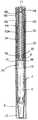
도 1은 제 1의 위치에서 카트리지가 가득 찬 상태의 본 발명과 관련된 약물 공급 장치의 제 1 실시예에 대한 단면도.1 is a cross-sectional view of a first embodiment of a drug supply device according to the present invention with the cartridge full in the first position;
도 2는 제 2의 위치에서 최대 제 1 투여량으로 다이얼 설정된 상태의 도 1의 약물 공급 장치의 단면도.FIG. 2 is a cross sectional view of the drug delivery device of FIG. 1 with the first dial dosed at a second position; FIG.
도 3은 제 3의 위치에서 최대 제 1 투여량으로 분배된 상태의 도 1의 약물 공급 장치의 단면도.3 is a cross-sectional view of the drug delivery device of FIG. 1 in a dispensed state at a maximum first dose in a third position.
도 4는 제 4의 위치에서 최종 투여량으로 다이얼 설정된 상태의 도 1의 약물 공급 장치의 단면도.4 is a cross-sectional view of the drug delivery device of FIG. 1 with the final dose dialed in a fourth position;
도 5는 제 5의 위치에서 최종 투여량으로 다이얼 설정된 상태의 도 1의 약물 공급 장치의 단면도.5 is a cross-sectional view of the drug delivery device of FIG. 1 with the final dose dialed in a fifth position;
도 6은 본 발명에 따른 약물 공급 장치의 제 2 실시예의 단면도.6 is a sectional view of a second embodiment of a drug delivery device according to the present invention;
도 7은 본 발명에 따른 약물 공급 장치의 제 3 실시예의 단면도.7 is a sectional view of a third embodiment of a drug delivery device according to the present invention.
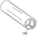
도 8은 본 발명과 관련되어 사용되는 투여량 다이얼 슬리브에 대한 투시도.8 is a perspective view of a dose dial sleeve used in connection with the present invention.
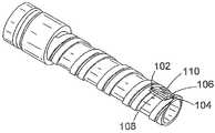
도 9는 도 8의 투여량 다이얼 슬리브와 함께 사용되는 인서트에 대한 투시도.9 is a perspective view of an insert for use with the dose dial sleeve of FIG. 8.
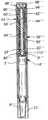
도 10은 본 발명에 따른 약물 공급 장치의 제 4 실시예의 단면의 측면도.10 is a side view of a cross section of a fourth embodiment of a drug delivery device according to the present invention;
도 11은 제 1의 위치에서 카트리지가 가득 찬 상태의 본 발명에 따른 구동 메커니즘의 제 5 실시예의 단면에 대한 측면도.FIG. 11 is a side view, in cross section, of a fifth embodiment of a drive mechanism according to the invention with the cartridge full in the first position; FIG.
실예 1Example 1
도 1 내지 도 5에 관하여, 본 발명의 제 1 실시예에 따른 약물 공급 장치가 도시된다. 이 장치는 의약품을 보관하는 카트리지(4)가 내부에 위치되는 하우징(2)과, 배출될 의약품의 투여량 설정 혹은 선택 수단 그리고 의약품의 선택된 투여량을 배출하기 위한 수단을 포함한다. 하우징(2)은 대체로 원통형 형상을 취하고, 하기 상세 기술될 웹(web, 6)에 의해 두 개의 구역으로 분할된다. 카트리지(4)는 하우징(2)의 제 1 부분 내에 위치된다. 투여량 설정 수단과 의약품의 선택된 투여량을 배출하기 위한 수단은 하우징(2)의 제 2 부분 내에 고정, 즉 유지된다. 투여량 설정 수단 그리고 투여량 배출 수단과 함께 카트리지(4)를 포함하는 단일 부품 하우징의 이점은 제품을 조립하는 경우에 존재한다. 이는 부분적으로 펜형 주사기에 있어서 감소된 부품수에 기인한다. 또한, 하우징(2)의 일체적 특성은 펜형이 보다 튼튼하다는 것을 의미한다.1 to 5, a drug supply device according to a first embodiment of the present invention is shown. The device comprises a housing (2) in which a cartridge (4) for storing a medicine is located, a means for setting or selecting a dose of the medicine to be discharged, and a means for discharging the selected dose of the medicine. The
카트리지(4)는 어떤 적절한 수단에 의해 하우징(2)의 제 1 부분의 최적 위치에 고정될 수 있다. 니들 유닛은 카트리지(4)의 제 1 단부에 고정될 수 있다. 임시 덮개(temporary covering, 8)는 도면에서 이 위치에 도시된다. 카트리지(4)는 위치이동가능한 피스톤(10)을 추가로 포함한다. 피스톤(10)을 카트리지(4)의 제 1 단부를 향해 이동시킴으로써 의약품이 카트리지(4)로부터 니들 유닛을 통해 배출된다. 캡(12)은 주사기가 사용되지 않을 때 니들 유닛을 덮기 위해 제공된다. 캡(12)은 어떤 적절한 수단에 의해 하우징에 해제가능하게 고정될 수 있다.The
투여량 설정 수단과 의약품의 선택된 투여량 배출 수단이 이하 상세히 기술 된다. 하우징(2)을 분할하는 웹(6)은 하우징(2)의 내에 위치되는 인서트(14)의 일부가 된다. 인서트(14)는 웹(6)의 제 1 측면으로부터 연장되는 제 1 원통부(16)와 웹(6)의 제 2 측면으로부터 연장되는 제 2와 제 3 원통부(18, 20)를 포함한다. 웹(6)은 이 웹(6)을 통과해서 연장되는 원형 개구(22)를 구비한다.The dose setting means and the selected dose dispensing means of the medicament are described in detail below. The
상기 제 1 원통부(16)는 웹(6)의 외주부로부터 연장된다. 인서트(14)는 어떤 적절한 수단에 의해 제 1 원통부를 거쳐 하우징에 고정된다. 도시된 실시예에서 특징부(24)가 하우징(2)의 내부에 제 1 원통부(16)의 외측면 상에 제공되어서 인서트는 하우징(2)에 스냅 끼워맞춤(snap fit)된다.The first
제 2 원통부(18)는 개구(22)의 외주를 중심으로 웹(6)의 제 2 측면으로부터 미소 거리만큼 연장된다. 제 2 원통부의 내측면은 나사(26)를 구비한다.The second
제 3 원통부(20)는 거의 웹(6)의 제 2 측면으로부터 하우징(2) 내에서 연장된다. 제 3 원통부의 직경은 제 2 원통부(20)의 외측면과 제 3 원통부의 내측면 사이에서 제 1 채널이 형성되도록 설정된다. 제 2 채널(30)은 제 3 원통부(20)의 외측면과 하우징(2) 사이에 형성된다.The third
피스톤 로드(32)는 웹(6)에서 상기 개구를 통과해서 연장된다. 피스톤 로드(32)는 대체로 가늘고 긴 형상(elongate)을 취하며, 피스톤 로드(32)의 제 1 단부로부터 연장된 나사(34)를 구비한다. 피스톤 로드(32)의 나사(34)는 인서트(14)의 제 2 원통부(18)의 내측면의 나사와 맞물리게 된다. 피스톤 로드(32)의 제 1 단부는 압력 풋(pressure foot, 36)을 구비한다. 실시에 있어서, 압력 풋(36)은 웹(6)의 제 1 측면 상에 배치되어서 카트리지 피스톤(10)과 접하게 된다.The
래칫 수단(40)은 웹(6)의 제 1 측면 상에서 웹(6)에 인접해서 위치된다. 래칫 수단(40)은 피스톤 로드(32)가 단일방향으로만 인서트를 통해서 회전하도록 하는 역할을 한다. 하우징의 단일 부품 구성 때문에, 래칫 수단은 공지된 장치들보다 더 크게 형성될 수 있고, 보다 더 강하게(보다 강성이 있게) 형성될 수 있다.The ratchet means 40 is located adjacent to the
대체로 원통형상을 취하는 투여량 다이얼 슬리브(50)는 제 1 직경을 갖는 제 1 구역과 제 2 직경을 갖는 제 2 구역을 포함한다. 제 1 구역은 제 2 채널(30)의 내부에 위치된다. 제 1 구역의 내측면과 제 3 원통부(20)의 외측면은 상호맞물림 특징부를 구비하여서 인서트(14)와 투여량 다이얼 슬리브(50) 사이에 헬리컬 나사(52)를 제공한다. 도시된 실시예에서 이는 제 3 원통부(20)의 외측면 상에 제공된 헬리컬 트랙에 의해 달성되고, 투여량 다이얼 슬리브(50)의 내측면 상에 제공된 헬리컬 리브가 이 원통부 내에서 진행할 수 있다. 이는 투여량 다이얼 슬리브(50)가 인서트(14)의 제 3 원통부(20)를 중심으로 그리고 이를 따라서 회전하는 것을 가능하게 한다.The
투여량 다이얼 슬리브(50)의 제 1 구역의 외측면은 그래픽표시(graphic, 53)를 구비한다. 이 그래픽표시는 전형적으로 연속된 기준 숫자열이 된다. 하우징(2)은 개구 혹은 창(54)을 구비하고, 이를 통해 사용자에 의해 선택된 투여량을 표시하는 그래픽 표시의 일부분이 관찰될 수 있다.The outer side of the first zone of the
그래픽표시(53)는 어떤 적절한 수단에 의해 투여량 다이얼 슬리브(50)에 가해질 수 있다. 도시된 실시예에서 그래픽표시(53)는 투여량 다이얼 슬리브(50)를 둘러싸는 인쇄된 라벨의 형태로 제공된다. 대안적으로 이 그래픽표시는 투여량 다 이얼 슬리브(50)에 클립핑된(clipped) 마킹 슬리브(marked sleeve)의 형태를 취할 수도 있다. 그래픽표시는 레이저 마킹과 같은 어떤 적절한 수단으로 마킹될 수 있다.
이러한 배열의 이점은, 투여량 다이얼 슬리브와 인서트 사이에서 투여량 다이얼 슬리브 내에 헬리컬 나사(52)가 형성된다는 점이다. 도시된 바와 같이, 이는 주사기의 외부로부터 헬리컬 나사의 작업면에 이르는 어떠한 직접 경로로 존재하지 않는다는 것을 의미한다. 먼지 혹은 분진 등이 펜으로 진입하게 된다면, 이는 하우징과 투여량 다이얼 슬리브 사이, 서로 간섭하는 작동 부품이 존재하지 않는 곳에서 발생하게 될 것이다. 이는 헬리컬 나사가 하우징과 내부 이동면 사이에 형성되는 공지된 장치에 대해서는 적용되지 않는다. 게다가 하우징과 투여량 다이얼 슬리브 사이에 형성된 유사한 나사에 비해서 투여량 다이얼 슬리브와 구동 슬리브 사이에 형성된 헬리컬 나사(52)의 직경이 더 협소하기 때문에, 헬리컬 나사(52)는 분해하기에 더욱 효율적이고 용이하다. 또한 이러한 배열은 공급될 수 있는 투여량 크기에 있어서 투여량 배출 수단의 특정한 선형 이동을 개선한다.An advantage of this arrangement is that a
투여량 다이얼 슬리브(50)의 제 2 구역은 양호하게 하우징(2)의 외경과 동일한 외경을 갖는다. 투여량 다이얼 슬리브(50)의 내부에는 투여량 다이얼 슬리브(50)의 제 1 구역과 투여량 다이얼 슬리브(50)의 제 2 구역 사이에 숄더(shoulder, 56)가 존재한다.The second zone of the
대체로 원통형을 취하는 구동 슬리브(60)는 제 1 직경을 갖는 제 1 부분과 제 2 직경을 갖는 제 2 부분을 포함한다. 제 1 부분의 제 1 단부는 도 1에 도시된 위치에서 인서트(14)의 제 1 채널(28) 내부에 위치된다. 구동 슬리브(60)의 제 1 부분은 제 2 부분과 정렬된 제 1 부분을 포함하는 것으로 간주될 수 있다. 도 1에 도시된 위치에서 좀더 일반적으로 구동 슬리브(60)의 제 1 부분은 인서트(14)와 피스톤 로드(32) 사이에 위치되고, 반면에 제 2 부분은 피스톤 로드(32)와 투여량 다이얼 슬리브(50) 사이에 위치된다.The
피스톤 로드(32)의 제 2 단부와 구동 슬리브(60)의 내측면은 서로 스플라인결합(splined)되어서, 이들 사이에서 종방향 이동을 제외한 어떠한 회전도 발생하지 않는다.The second end of the
구동 슬리브(60)의 제 1 부분의 제 2 부위의 외측면은 헬리컬 나사(62)를 구비한다. 너트(64)는 구동 슬리브(60)와 투여량 다이얼 슬리브(50) 사이에서 헬리컬 나사(62) 상에 제공된다. 투여량 다이얼 슬리브(50)와 너트(64)는 스플라인 수단에 의해서 서로 스플라인결합되어서 너트(64)와 투여량 다이얼 슬리브(50) 사이에서 상대적 회전이 차단된다.The outer surface of the second portion of the first portion of the
구동 슬리브(60)의 제 2 부분은 구동 슬리브(60)의 제 1 부분보다 더 큰 직경을 갖는다. 구동 슬리브(60)의 제 1 부분과 제 2 부분 사이에는 계단부(step, 66)가 존재한다. 구동 슬리브(60)의 제 2 부분은 투여량 다이얼 슬리브(50)의 제 2 구역 내에 안착된다. 투여량 다이얼 슬리브(50)의 숄더(56)와 구동 슬리브(60)의 계단부(66)는 클러치 수단을 형성하도록 서로 해제가능하게 맞물림되기에 적합하다. 도 1에서와 같이 투여량 다이얼 슬리브(50)와 구동 슬리브(60)가 맞물림상태에 있지 않을 때 투여량 다이얼 슬리브(50)는 구동 슬리브(60)에 대해서 회전할 수 있 다. 편리하게, 클러치 수단은 투여량 다이얼 슬리브(50)의 숄더(56)와 구동 슬리브(60)의 계단부(66) 상에 각각 제공된 다수의 반경방향으로 연장되고 종방향으로 지향된 치형을 포함한다. 투여량 다이얼 슬리브(50)와 구동 슬리브(60)가 서로 가압하지 않을 때 각각의 치형은 서로를 타고 넘게 될 것이다. 양호하게, 각각의 치형의 반경방향 간격은 단위 투여량에 대응된다.The second portion of the
구동 슬리브(60)의 제 2 부분은 외주 리세스(peripheral recess)를 구비한 중앙 수용 지역(68)을 추가로 포함한다. 대체로 "T"자형 구성을 갖고, 그 몸통부(stem)는 상기 수용 지역 내에 고정되는 버튼(70)이 제공된다. 버튼(70)의 몸통부는 외주 리세스에 고정되는 외주 비드(peripheral bead, 71)를 구비하여서, 버튼(70)은 구동 슬리브에 대해서 자유롭게 회전할 수 있지만, 이들 사이에서 축방향으로는 고정된다.The second portion of the
클리커 수단은 투여량 다이얼 슬리브(50)의 제 2 구역과 구동 슬리브(60)의 제 2 부분 사이에 제공된다. 도시된 실시예에서, 투여량 다이얼 슬리브(50)의 제 2 구역의 내측면은 다수의 종방향 연장 치형을 구비한다. 치형의 반경방향 간격은 양호하게 단위 투여량에 대응된다. 구동 슬리브(60)의 제 2 부분은 가요성 치형 부재(72)를 포함한다. 투여량 다이얼 슬리브(50)와 구동 슬리브(60) 사이의 상대적 회전으로 인해서 이 가요성 치형 부재(72)는 연속된 딸깍음을 형성하면서 치형을 타고 넘게 된다.Clicker means are provided between the second zone of the
도 1에서, 주사기는 충전된 카트리지(4)를 구비한다. 주사기를 작동시키기 위해서 사용자는 최초에 투여량을 선택해야 한다. 투여량을 설정하기 위해 투여량 다이얼 슬리브(50)는, 원하는 투여량 값이 창(54)을 통해 보이게 될 때까지 하우징에 대해 투여량 다이얼 슬리브(50)의 제 2 구역을 조작함으로써 회전된다. 이러한 행위로 인해서 투여량 다이얼 슬리브(50)가 인서트(14)의 제 2 원통부를 따라서 당겨진다. 구동 슬리브(60)는 피스톤 로드(32)에 스플라인결합되어 있어서 회전할 수 없게 된다. 피스톤 로드(32)는 래칫 수단(40)의 작용으로 인해서 회전되지 않는다. 투여량 다이얼 슬리브(50)가 하우징(2)으로부터 멀어지면서 이동할 때, 구동 슬리브(60)는 투여량 다이얼 슬리브(50)에 의해 피스톤 로드(32)를 따라 웹(6)으로부터 멀어지게 이동된다. 투여량 다이얼 슬리브(50)와 구동 슬리브(60) 사이의 상대적 회전으로 인해서 가요성 치형 부재(72)는 구동 슬리브(60)에서 능선(ridge)을 타고 넘게 되어서 연속된 딸깍음을 형성하게 된다. 이는 다이얼 설정된 투여량에 대한 청각적 확인에 해당하게 된다.In FIG. 1, the syringe has a filled
너트(64)는 투여량 다이얼 슬리브(50)에 스플라인결합되기 때문에, 투여량 다이얼 슬리브(50)와 구동 슬리브(60) 사이의 상대적 회전에 의해서 너트(64)는 구동 슬리브(60)의 헬리컬 나사(62)를 따라 진행하게 된다.Since the
일단 원하는 투여량이 설정되면 (도 2에서 예시적으로 도시된 바와 같이), 투여량을 공급하기 위해 사용자는 버튼(70)을 눌러서 버튼(70)을 하우징(2)의 제 1 단부를 향해 가압한다. 버튼(70)이 가압될 때, 구동 슬리브(60)의 제 2 부분은 투여량 다이얼 슬리브(50)의 제 2 구역으로 진입하여 이들 사이에서 클러치 수단과 맞물리게 되어서 투여량 다이얼 슬리브(50)와 구동 슬리브(60) 사이의 상대적 회전은 차단된다. 구동 슬리브(60)는 아직 버튼(70)에 대해서 회전할 수 있다. 버튼 (70)의 추가적 종방향 이동으로 인해서 (구동 슬리브(60)와 함께) 투여량 다이얼 슬리브(50)는 주사기의 제 1 단부를 향해 회전하게 된다. 피스톤 로드(32)는 구동 슬리브(60)에 스플라인결합되어 있기 때문에, 피스톤 로드(32)는 또한 인서트(14)와 래칫 수단(40)을 통해서 주사기의 제 1 단부를 향해 회전되고, 따라서 카트리지 피스톤(10)을 전진시키고 의약품의 원하는 투여량을 배출시킨다. 피스톤 로드(32)는 구동 슬리브(60)와 투여량 다이얼 슬리브(50)가 이들의 초기 위치(도 3)에 복귀할 때까지 계속해서 전진한다.Once the desired dosage has been set (as illustrated by way of example in FIG. 2), the user presses
투여량이 선택될 때 투여량 선택 수단과 투여량 배출 수단이 하우징(2)의 제 2 단부를 넘어 연장되고, 선택된 투여량이 배출될 때 이들이 하우징(2) 내로 복귀된다는 것을 알 수 있다.It can be seen that the dose selection means and the dose dispensing means extend beyond the second end of the
원한다면 추가의 투여량이 공급될 수 있다. 도 4는 다음 단계에서 선택된 투여량의 예를 도시한다. 너트(64)가 구동 슬리브(60)의 헬리컬 나사(62)를 따라 추가로 진행되었음을 알 수 있다. 헬리컬 나사(62)에 따른 너트(64)의 위치는 카트리지(4)에 잔존하는 의약품의 총량에 대응되고, 따라서 (구동 슬리브(60)의 계단부(66)에 인접한 도시된 실시예에서) 너트(64)가 헬리컬 나사(62)의 단부에 도달하고 더 이상 회전할 수 없게 될 때 이는 카트리지(4)에 잔존하는 의약품이 없다는 것에 대응된다. 사용자가 카트리지(4)에 잔존하는 양보다 더 많은 의약품의 양을 선택한다면, 이는 실행될 수 없는데, 왜냐하면 너트(64)가 회전을 정지할 때 투여량 다이얼 슬리브(50)와 구동 슬리브(60)는 서로 체결되어서 투여량 다이얼 슬리브(50)의 회전과 더 많은 투여량의 설정은 차단되기 때문이다. 도 5는 본 발명에 따른 주사 기를 도시하고, 여기서 카트리지(4) 내의 전체 의약품은 배출된 상태가 된다.Additional dosages may be supplied if desired. 4 shows an example of the dosage selected in the next step. It can be seen that the
본 발명의 제 2 실시예는 도 6에 도시된다. 제 1과 제 2 실시예 사이에서와 같이 유사 부분을 언급하기 위해 유사한 참조 번호가 사용된다.A second embodiment of the present invention is shown in FIG. Like reference numerals are used to refer to like parts, as between the first and second embodiments.
도 6에 도시된 피스톤 로드(32')는 이중 개시 나사(dual start thread)를 구비한다. 피스톤 풋(piston foot, 36')은 가역적이다. 이는 생산에 있어서 이점을 갖는다. 도시된 바와 같이 인서트(14')의 구조는 수정되어 있다. 웹(6')의 제 2 측면은 거의 변화되지 않았다. 웹의 다른 측면은 이제 보스(boss, 80)를 구비한다. 원통부(20')는 웹(6')으로부터 멀어져서 보스(80)의 외주를 중심으로 연장된다. 나사형성 개구(22")는 웹(6')과 보스(80)를 통과해서 연장된다. 웹(6')으로부터 멀리 떨어진 인서트(14')의 원통부(20')의 단부는 랜드(land, 104)의 형태로 멈춤부를 구비한다.The
투여량 다이얼 슬리브(50')는 수정된 구성을 갖는다. 투여량 다이얼 슬리브는 대체적인 제 2 원통부에 강체 결합된 제 1 원통부(84)를 포함한다. 제 1 원통부(84)의 내측면과 인서트(14')의 원통부(20')의 외측면은 상호맞물림 특징부를 구비하여서 인서트(14')와 투여량 다이얼 슬리브(50') 사이에 헬리컬 나사(52')가 제공된다. 제 1 원통부(84)의 외측면은 투여량 그래픽표시를 구비한다. 하우징(2')은 개구 혹은 창(54')을 구비하고, 이 창을 통해서 그래픽표시의 일부분이 관찰될 수 있다.
대체적인 제 2 원통부(86)는 제 1 원통구역(88)과 제 2 원통구역(90)을 포함한다. 이 제 1 구역(88)은 투여량 다이얼 슬리브(50')의 제 1 부위(84)의 내측면과 강체 연결된다. 제 2 구역(90)은 양호하게 하우징(2')과 동일한 외경을 갖는다. 투여량 다이얼 슬리브(50') 내부에는 제 1 구역(86)과 제 2 구역(90) 사이에서 숄더(56')가 존재한다.The second alternative
너트(64')는 구동 슬리브(60')와 투여량 다이얼 슬리브(50')의 제 1 원통구역(88) 사이에서 헬리컬 나사(62') 상에 제공된다. 제 1 원통구역(88)과 너트(64')는 스플라인 수단에 의해서 서로 스플라인결합되어 너트(64')와 투여량 다이얼 슬리브(50') 사이의 상대적 회전은 차단된다.A nut 64 'is provided on the helical screw 62' between the drive sleeve 60 'and the first
투여량 다이얼 슬리브(50')의 숄더(56')와 구동 슬리브(60')의 계단부(66')는 서로 해제가능하게 맞물림되어서 클러치 수단을 형성하기에 적합하다. 도 6에서와 같이 투여량 다이얼 슬리브(50')와 구동 슬리브(60')가 물림상태에 있지 않을 때 투여량 다이얼 슬리브(50')는 구동 슬리브(60')에 대해서 회전할 수 있게 된다. 편리하게, 클러치 수단은 투여량 다이얼 슬리브(50')의 숄더(56')와 구동 슬리브(60')의 계단부(66') 상에 각각 제공된 반경방향으로 연장된 종방향 지향 치형을 포함한다. 투여량 다이얼 슬리브(50')와 구동 슬리브(60')가 서로에 대해서 가압되지 않을 때 각각의 치형은 서로를 타고 넘게 될 것이다.The shoulder 56 'of the
구동 슬리브(60')의 구조가 또한 수정된 것을 알게 될 것이다. 피스톤 로드(32')의 제 2 단부는 구동 슬리브(60')의 돔형 부분(domed part, 90)이 내부에서 연장될 수 있는 패인 표면(scooped surface)을 구비한다. 이 돔형 부분(90)은 구동 슬리브(60')의 제 2 부분 내에서 수용 지역의 제 1 단부의 중심에 위치된다.It will be appreciated that the structure of the drive sleeve 60 'has also been modified. The second end of the piston rod 32 'has a scooped surface through which a
버튼(70')은 대체로 "T"자형의 구성을 취한다. 이 버튼(70')의 몸통부는 수 용 지역에 고정된다. 버튼(70')의 몸통부는 외주 리세스에 고정되는 외주 비드(71')를 구비하여서, 버튼(70')은 구동 슬리브(60')에 대해서 자유롭게 회전할 수 있지만 이들 사이에서 축방향으로는 고정된다.The button 70 'generally takes the form of a "T" shape. The body of this button 70 'is fixed to the receiving area. The body of the button 70 'has a circumferential bead 71' secured to the circumferential recess so that the button 70 'can rotate freely with respect to the drive sleeve 60' but in axial direction therebetween. It is fixed.
버튼(70')이 눌러질 때, 구동 슬리브(60')는 투여량 다이얼 슬리브(50')와 접촉하도록 가압되어서 클러치 수단이 맞물리게 된다. 동시에, 피스톤 로드(32')의 패인 표면과 구동 슬리브의 돔형 표면은 서로 접근하지만 접촉하지는 않는다. 이러한 구조의 이점은 이로써 장치의 전체 길이가 감소될 수 있고, 이에 따라 카트리지로부터 유체를 추출할 때 장치의 작동을 더욱 용이하게 할 수 있다는 점이다.When the button 70 'is depressed, the drive sleeve 60' is pressed to contact the
버튼(70")과 투여량 다이얼 슬리브(50")의 추가적인 실시예를 도 7에서 볼 수 있다. 마찬가지로 유사한 부분에 대해서 유사한 참조 번호가 사용된다. 도 7의 실시예에서, 장치의 전체 길이는 추가적으로 감소될 수 있다. 피스톤 로드(32")의 제 2 단부는 대체로 U-자형상을 취한다. U-자형에서 가지(limb)는 구동 슬리브(60")의 제 2 부분 내에 수용된다. 구동 슬리브(60")의 중앙 수용 지역은 피스톤 로드(32")의 제 2 단부 상에 형성된 가지들 사이에서 사용되도록 위치된 (도시되지 않은) 가지들에 의해 한정된다. 버튼(70")은 대체로 "T"자 형상을 취한다. 버튼(70")의 몸통부는 상기 수용지역 내에 고정된다. 버튼(70")의 몸통부는 외주 리세스에 고정되는 외주 비드(71")를 구비하여서, 버튼(70")은 구동 슬리브(60")에 대해서 자유롭게 회전할 수 있지만, 이들 사이에서 축방향으로는 고정된다.Additional embodiments of the
투여량 다이얼 슬리브(50")의 대체적인 제 2 원통부(86")는 제 1 원통구역(88")과, 제 2 구역의 일부분으로부터 연장된 반경방향 플랜지(radial flange, 92) 에 의해 연결된 제 2 원통구역(90")을 포함하고, 여기서 제 1 구역(88")은 투여량 다이얼 슬리브(50")의 제 2 부분(84")의 내측면에 강체 결합되고 제 2 구역(90")은 하우징(2")과 동일한 외경을 갖게 된다.An alternate second
도 6과 도 7의 각각에는 투여량 다이얼 슬리브와 인서트 각각에 대한 추가적 수정예가 존재한다. 이는 도 8과 도 9를 참조할 때 더욱 확실히 알 수 있다.In each of FIGS. 6 and 7 there are additional modifications to each of the dose dial sleeve and insert. This can be more clearly seen with reference to FIGS. 8 and 9.
투여량 다이얼 슬리브의 제 1 단부에는 내측면 상에 이 슬리브의 종방향 축에 대체로 평행하게 연장되는 반경방향 지향 러그(lug, 100)가 위치된다. 인서트의 제 2 단부에는 그 외측면 상에 클러치 수단이 제공된다. 클러치 수단은 중앙 랜드(104)를 중심으로 연장된 홈(102)을 포함한다. 이 중앙 랜드(104)는 대체로 쐐기형상(wedge shaped)으로 이루어져서, 나사의 시작부에 더 가까이에 있는 제 1 에지(106)는 나사를 따라서 더 멀리에 위치된 제 2 대향 에지보다 덜 반경방향으로 연장된다. 경사면(sloping surface, 110)은 제 1 에지(106)와 제 2 에지(108) 사이에서 한정된다. 따라서, 투여량 다이얼 슬리브가 인서트에 조립될 때, 투여량 다이얼 슬리브를 인서트 상으로 나사결합시킴으로써 상기 러그(10)는 제 1 에지(106)를 지나서 그리고 경사면(110)을 지나서 통과한다. 상기 러그(100)가 상기 랜드(104)를 지나 충분히 통과할 때, 투여량 다이얼 슬리브와 인서트 각각의 요소들의 탄성 변형이 발생한다. 일단 러그(100)가 랜드(04) 위에 존재하게 되면, 랜드(104)의 제 2 에지(108)는 인서트로부터 투여량 다이얼 슬리브의 이탈을 막기 위한 멈춤부로서 작용한다.At the first end of the dose dial sleeve is located a radially oriented
랜드(104)의 제 2 에지(108)의 위치는 의약품의 80 단위(unit)에 해당하는 반경방향 위치에서 편리하게 선택되고, 즉 투여량 다이얼 슬리브가 랜드(104)의 제 2 에지(108)가 상기 러그(100)와 접촉한 상태로 도 1, 6 혹은 7 중의 어느 하나에 도시된 초기 위치로부터 완전 연장된 위치로 감기게 될 때 유효한 최대 투여량은 80 단위가 된다.The position of the
본 발명의 제 4 실시예는 도 10에 도시된다. 유사한 부분에 관해서는 유사한 참조 번호가 사용된다.A fourth embodiment of the present invention is shown in FIG. Similar reference numerals are used for similar parts.
도시된 바와 같이 인서트(14''')의 구조는 수정되어 있다. 웹(6''')의 제 1 측면은 거의 변화가 없다. 웹의 다른 측면은 이제 보스(80''')를 구비한다. 반경방향 플랜지(112)는 이 보스(80''')로부터 외부를 향해 연장되고, 이 반경방향 플랜지(112)는 웹(6''')으로부터 이격되어 있으며, 원통부(20''')는 반경방향 플랜지(110)의 외주를 중심으로 웹(6''')으로부터 멀어지면서 연장된다, 나사형성 개구(22''')는 이 웹(6''')과 보스(80''')를 통과해서 연장된다.As shown, the structure of the insert 14 '' 'has been modified. The first side of the web 6 '' 'hardly changes. The other side of the web now has a boss 80 '' '. The
투여량 다이얼 슬리브(50''')는 수정된 구성을 취한다. 투여량 다이얼 슬리브(50''')는 대체적인 제 2 원통부(86''')에 강체 연결되는 제 1 원통부(84''')를 포함한다. 이 제 1 원통부(84''')의 내측면과 인서트(14''')의 원통부(20''')의 외측면은 상호물림 특징부를 구비하여서 인서트(14''')와 투여량 다이얼 슬리브(50''') 사이에 헬리컬 나사(52''')를 제공한다. 제 1 원통부(84''')의 외측면은 투여량 그래픽표시를 구비한다. 하우징(2''')은 개구 또는 창(54''')을 구비하고, 이 창을 통해서 상기 그래픽표시의 일부가 관찰될 수 있다.
대체적인 제 2 원통부(86''')는 제 1 내부 원통구역(88''')과 제 2 외부 원 통구역(90''')을 포함한다. 제 1 구역(88''')은 투여량 다이얼 슬리브(50''')의 제 1 부위(84''')의 내측면에 강체 결합된다. 제 2 구역(90''')은 양호하게 하우징(2''')과 동일한 외경을 갖는다. 투여량 다이얼 슬리브(50''')의 내부에는 외부 구역(90''')과 내부 구역(88''')의 매개부 사이에서 연장되는 반경방향 플랜지(94)가 존재한다.An alternative second cylindrical portion 86 '' 'includes a first inner cylindrical region 88' '' and a second outer cylindrical region 90 '' '. The first zone 88 '' 'is rigidly coupled to the inner side of the first portion 84' '' of the
너트(64''')는 구동 슬리브(60''') 상에 형성되는 헬리컬 나사(62''') 상에 제공된다. 너트(64''')는 구동 슬리브(60''')와 투여량 다이얼 슬리브(50''')의 제 2 원통구역(88''') 사이에 배치된다. 제 2 원통구역(88''')과 너트(64''')는 스플라인 수단에 의해 함께 고정되어서 너트(64''')와 투여량 다이얼 슬리브(50''') 사이의 상대적 회전이 차단된다.The nut 64 '' 'is provided on a helical screw 62' '' formed on the drive sleeve 60 '' '. The nut 64 '' 'is disposed between the drive sleeve 60' '' and the second cylindrical section 88 '' 'of the
투여량 다이얼 슬리브(50''')의 반경방향 플랜지(94)의 상단면과 구동 슬리브(60''')의 계단부(66''')는 서로에 대해 해제가능하게 맞물림되어 클러치 수단을 형성하기에 적합하다. 도 10에서와 같이, 투여량 다이얼 슬리브(50''')와 구동 슬리브(60''')가 맞물림 상태에 있지 않을 때 투여량 다이얼 슬리브(50''')는 구동 슬리브(60''')에 대해서 회전할 수 있다. 편리하게, 클러치 수단은 투여량 다이얼 슬리브(50''')의 반경방향 플랜지(94)와 구동 슬리브(60''')의 계단부(66''') 상에 각각 제공되는 다수의 반경방향 연장 종방향 지향 치형을 포함한다. 투여량 다이얼 슬리브(50''')와 구동 슬리브(60''')가 서로에 대해서 가압되지 않을 때 각각의 치형은 서로를 타고 넘게 될 것이다.The top surface of the radial flange 94 of the
실예 2Example 2
본 발명의 다른 실시예(도 11)에는 제 1 단부와 제 2 단부를 구비한 제 2 메인 하우징(4')을 포함하는 구동 메커니즘이 도시된다. 의약품을 보관하는 카트리지는 제 2 메인 하우징(4')의 제 1 단부에 설치될 수 있고, 적절한 수단에 의해서 고정될 수 있다. 카트리지와 그 고정 수단은 도시된 실시예에는 도시되지 않는다. 카트리지는 의약품의 다수의 투여량을 보관할 수 있고 또한 전형적으로 위치이동가능한 피스톤을 포함할 수 있다. 피스톤의 위치이동으로 인해서 의약품은 (마찬가지로 도시되지 않은) 니들을 통해 카트리지로부터 배출된다.Another embodiment of the invention (FIG. 11) is shown a drive mechanism comprising a second
도시된 실시예에서, 인서트(16')는 메인 하우징(4')의 내부에 제공된다. 인서트(16')는 제 2 메인 하우징(4')에 대한 회전과 축방향 운동을 방지하도록 고정된다. 인서트(16')는 이를 관통하여 연장되는 나사형성 원형 개구를 구비한다. 대안적으로, 인서트는 제 2 메인 하우징(4')과 일체로 형성될 수도 있다.In the embodiment shown, the insert 16 'is provided inside the main housing 4'. The insert 16 'is fixed to prevent rotation and axial movement with respect to the second main housing 4'. Insert 16 'has a threaded circular opening extending therethrough. Alternatively, the insert may be integrally formed with the second main housing 4 '.
또한 내부 하우징(154)은 제 2 메인 하우징(4')의 내부에 제공된다. 내부 하우징(154)은 제 2 메인 하우징(4')에 대한 회전과 축방향 운동을 방지하도록 고정된다. 내부 하우징(154)은 이를 관통해서 연장되고, 길이방향으로 연속된 종방향 지향 스플라인이 형성된 원형 개구를 구비한다. 헬리컬 나사(150)는 내부 하우징(154)의 외부 원통면을 따라 연장된다. 대안적으로, 내부 하우징은 제 2 메인 하우징(4') 및/혹은 인서트(16')와 일체로 형성될 수도 있다.The
제 1 나사(19')는 피스톤 로드(20")의 제 1 단부로부터 연장된다. 피스톤 로드(20")는 대체로 원형의 단면을 취한다. 피스톤 로드(20")의 제 1 단부는 인서트(16')에서 나사형성 개구를 통과해서 연장되고 피스톤 로드(20")의 제 1 나사(19') 는 인서트(16')의 나사와 맞물리게 된다. 압력 풋(22")은 피스톤 로드(20")의 제 1 단부에 위치된다. 압력 풋(22")은 (도시되지 않은) 카트리지 피스톤과 접하도록 배치된다. 제 2 나사는 피스톤 로드(20")의 제 2 단부로부터 연장된다. 제 1 나사(19')와 제 2 나사(24')는 대향하여 배치된다.The first screw 19 'extends from the first end of the
구동 슬리브(30')는 피스톤 로드(20")를 중심으로 연장된다. 구동 슬리브(30')는 대체로 원통형을 취한다. 구동 슬리브(30')는 그 제 1 단부에 제 1 반경방향 연장 플랜지(32")를 구비한다. 제 2 반경방향 연장 플랜지(34')는 제 1 플랜지(32")로부터 구동 슬리브(30')를 따라 일정거리만큼 이격되어 제공된다. (도시되지 않은) 외부 헬리컬 나사는 제 1 플랜지(32")와 제 2 플랜지(34') 사이에서 연장되는 구동 슬리브(30')의 외측부에 제공된다. 헬리컬 암나사는 구동 슬리브(30')의 내측면을 따라 연장된다. 피스톤 로드(20")의 제 2 나사(24')는 구동 슬리브(30')의 헬리컬 암나사와 맞물리게 된다.The drive sleeve 30 'extends about the
너트(40')는 구동 슬리브(30')와 내부 하우징(154) 사이에 위치되고, 구동 슬리브(30')의 제 1 플랜지(32")와 제 2 플랜지(34') 사이에 배치된다. 너트(40')는 '하프-너트(half-nut)' 혹은 '풀-너트(full-nut)' 중의 어느 하나가 될 수 있다. 너트(40')는 구동 슬리브(30')의 외부 헬리컬 나사와 맞물리게 되는 암나사를 구비한다. 너트(40')의 외측면과 내부 하우징(154)의 내측면은 종방향 지향 스플라인에 의해서 서로 결합되어 너트(40')와 내부 하우징(154) 사이의 상대적 회전은 차단되지만, 이들 사이의 상대적 종방향 이동은 허용된다.The nut 40 'is positioned between the drive sleeve 30' and the
클리커(50'''')와 클러치(60'''')는 구동 슬리브(30')를 중심으로, 구동 슬 리브(30')와 내부 하우징(154) 사이에 배치된다.
클리커(50'''')는 구동 슬리브(30')의 제 2 플랜지(34')에 인접해서 위치된다. 클리커(50'''')는 (도시되지 않은) 최소한 하나의 스프링 부재를 포함한다. 또한 클리커(50'''')는 구동 메커니즘의 제 2 단부 주위에 배치되고 삼각형상을 갖는 (도시되지 않은) 한 세트의 치형을 포함한다. 압력을 받을 때, 클리커(50'''')의 최소한 하나의 스프링 부재는 구동 슬리브(30')의 플랜지(34')와 클러치(60'''') 사이에 축방향 힘을 가한다. 클리커(50'''')의 외측면과 내부 하우징(154)의 내측면은 종방향 지향 스플라인에 의해 함께 결합되어 클리커(50'''')와 내부 하우징(154) 사이의 상대적 회전은 차단되지만, 이들 사이의 상대적 종방향 이동은 허용된다.
클러치(60'''')는 구동 슬리브(30')의 제 2 단부에 인접해서 위치된다. 클러치(60'''')는 대체로 원통형상을 취하고, 그 제 1 단부에 (도시되지 않은) 원주 주위로 배치되고 클리커(50'''')에 작용하는 다수의 삼각형상을 가진 치형을 구비한다. 클러치(60'''')의 제 2 단부 부근에는 숄더(158)가 위치된다. 클러치(60'''')의 숄더(158)는 내부 하우징(154)과 (하기 기술되는) 투여량 다이얼 그립(76')의 반경방향 내부지향 플랜지 사이에 배치된다. 클러치(60'''')의 숄더(158)는 구동 메커니즘의 제 2 단부의 방향으로 연장되는 다수의 (도시되지 않은) 도그 치형을 구비한다. 클러치(60'''')는 (도시되지 않은) 스플라인에 의해 구동 슬리브(30')에 결합되어서 클러치(60'''')와 구동 슬리브(30') 사이의 상대적 회전은 차단된다.The clutch 60 '' '' is positioned adjacent to the second end of the drive sleeve 30 '. Clutch 60 '' '' takes a generally cylindrical shape and has a tooth with a plurality of triangular shapes disposed around its circumference (not shown) at its first end and acting on
투여량 다이얼 슬리브(70''')는 내부 하우징(154)의 외측에 그리고 제 2 메 인 하우징(4')으로부터 반경방향으로 내부를 향해 제공된다. 헬리컬 나사는 투여량 다이얼 슬리브(70''')의 내측면 상에 제공된다. 투여량 다이얼 슬리브(70''')의 헬리컬 나사는 내부 하우징(154)의 헬리컬 나사(150)와 맞물리게 된다.The dose dial sleeve 70 '' 'is provided on the outside of the
제 2 메인 하우징(4')은 투여량 다이얼 슬리브(70''')의 외측면의 일부가 관찰될 수 있는 (도시되지 않은) 창을 구비한다. 편리하게, 다이얼 설정될 수 있는 투여량에 대한 시각적 지표, 예를 들면 (도시되지 않은) 참조 숫자열이 투여량 다이얼 슬리브(70''')의 외측면 상에 제공된다. 편리하게, 제 2 메인 하우징(4')의 창에 의해서 현재 다이얼 설정된 투여량만이 관찰된다.The second main housing 4 'has a window (not shown) in which a portion of the outer side of the dose dial sleeve 70' '' can be observed. Conveniently, a visual indicator of the dose that can be dialed, for example a reference string (not shown), is provided on the outer side of the dose dial sleeve 70 '' '. Conveniently, only the dose currently set by the window of the second main housing 4 'is observed.
투여량 다이얼 그립(76')은 구동 메커니즘의 제 2 단부 부근에 위치된다. 투여량 다이얼 그립(76')은 투여량 다이얼 슬리브(70''')에 대해서 회전과 축방향 이동을 하지 못하도록 고정된다. 투여량 다이얼 그립(76')은 반경방향 내부지향 플랜지(160)를 구비한다. 투여량 다이얼 그립(76')의 반경방향 내부지향 플랜지(160)는 구동 메커니즘의 제 1 단부의 방향으로 연장되는 (도시되지 않은) 다수의 도그 치형을 구비하여서, 클러치(60'''')의 도그 치형과 접하게 된다. 투여량 다이얼 그립(76')의 도그 치형과 클러치(60'''')의 도그 치형의 결합과 분리는 투여량 다이얼 그립(76')과 클러치(60'''') 사이에 해제가능한 클러치를 제공한다.The dose dial grip 76 'is located near the second end of the drive mechanism. The dose dial grip 76 'is secured against rotation and axial movement with respect to the dose dial sleeve 70' ''. The
대체로 "T"자형 단면을 가진 버튼(82')이 구동 메커니즘의 제 2 단부에 제공된다. 버튼(82')의 원통형 특징부는 구동 메커니즘의 제 1 단부 부근에서 투여량 다이얼 그립(76')에서 개구를 통과하여 구동 슬리브(30')에서 리세스로 진입하여 연장된다. 버튼(82')의 원통형 특징부는 구동 슬리브(30')에서 제한된 축방향 이동을 위해 그리고 이들 사이의 회전을 제한하도록 고정된다. 버튼(82')의 원통형 특징부는 클러치(60'''')의 숄더(158)의 제 2 면과 접하는 (도시되지 않은) 반경방향 연장 러그를 구비한다. 버튼(82')의 제 2 단부는 대체로 원통형을 취하고, 구동 메커니즘의 제 1 단부를 향해 하강하는 그 외주 주위에서 원통형 테두리부(skirt)를 구비한다. 버튼(82')의 테두리부는 투여량 다이얼 그립(76')으로부터 반경방향으로 내부를 향해 위치된다.A button 82 'having a generally "T" shaped cross section is provided at the second end of the drive mechanism. The cylindrical feature of the button 82 'passes through the opening in the dose dial grip 76' near the first end of the drive mechanism and enters and extends into the recess in the drive sleeve 30 '. The cylindrical feature of the button 82 'is fixed for limited axial movement in the drive sleeve 30' and to limit rotation therebetween. The cylindrical feature of the button 82 'has a radially extending lug (not shown) that abuts the second side of the
본 발명에 관한 구동 메커니즘의 작동은 이하 기술된다.The operation of the drive mechanism according to the invention is described below.
투여량을 다이얼 설정하기 위해, 사용자는 투여량 다이얼 그립(76')을 회전시킨다. 클리커(50'''')의 스프링 부재는 구동 메커니즘의 제 2 단부의 방향으로 클러치(60'''')에 축방향 힘을 가한다. 클리커(50'''')의 스프링 부재에 의해 가해진 힘은 클러치(60'''')의 도그 치형을 투여량 다이얼 그립(76')의 도그 치형에 회전을 위해 연결시킨다. 투여량 다이얼 그립(76')이 회전됨에 따라서, 관련된 투여량 다이얼 슬리브(70''''), 구동 슬리브(30') 그리고 클러치(60'''') 모두는 동조하여 회전한다.To dial the dose, the user rotates the dose dial grip 76 '. The spring member of the
다이얼 설정된 투여량에 대한 청각적 그리고 촉각적 피드백이 클리커(50'''')와 클러치(60'''')에 의해 제공된다. 클러치(60'''')가 회전됨에 따라서, 토크가 클러치(60'''')의 제 1 단부의 치형으로부터 클리커(50'''')의 치형으로 전달된다. 클리커(50'''')는 내부 하우징(154)에 대해서는 회전할 수 없어서, 클리커(50'''')의 최소한 하나의 스프링 부재는 변형하여 클러치(60'''')의 치형이 클리커(50'''')의 치형을 뛰어 넘도록 하여 청각적 그리고 촉각적 '딸깍음(click)'이 생성된다. 양호하게, 클리커(50'''')의 치형과 클러치(60'''')의 치형은 '딸깍음'이 의약품의 통상적인 단위 혹은 그와 같은 것에 대응되도록 배치된다.Acoustic and tactile feedback for the dialed dose is provided by the
투여량 다이얼 슬리브(70''')의 헬리컬 나사와 구동 슬리브(30')의 내부 헬리컬 나사는 동일한 리드길이를 갖는다. 이로써 투여량 다이얼 슬리브(70''')는 내부 하우징(154)의 나사(150)를 따라 구동 슬리브(30')가 피스톤 로드(20")의 제 2 나사(24')를 따라 전진하는 속도와 동일한 속도로 진행하게 된다. 피스톤 로드(20")의 회전은 피스톤 로드(20")의 제 1 나사(19')와 제 2 나사(24')의 대향 방향 때문에 차단된다. 피스톤 로드(20")의 제 1 나사(19')는 인서트(16')의 나사와 맞물리게 되고, 따라서 피스톤 로드(20")는 투여량이 다이얼 설정되는 동안 제 2 메인 하우징에 대해서 이동하지 않게 된다.The helical screw of the dosage dial sleeve 70 '' 'and the internal helical screw of the drive sleeve 30' have the same lead length. This allows the dose dial sleeve 70 '' 'to move along the
내부 하우징(154)에 결합된 너트(40')는 구동 슬리브(30')의 회전에 의해서 구동 슬리브(30')의 수나사를 따라 전진된다. 사용자가 카트리지의 공급가능한 양과 동등한 양의 의약품을 다이얼 설정할 때, 너트(40')는 구동 슬리브(30')의 제 2 플랜지(34')와 접하는 위치에 도달한다. 너트(40')의 제 2 면에 형성된 반경방향 멈춤부는 구동 슬리브(30')의 제 2 플랜지(34')의 제 1 면 상에서 반경방향 멈춤부와 접촉하여 너트(40')와 구동 슬리브(30') 모두의 추가적인 회전은 차단된다.The nut 40 'coupled to the
사용자가 부주의하게 원하는 투여량보다 더 많은 양을 다이얼 설정하게 된다면, 구동 메커니즘은 카트리지로부터 의약품을 분배하지 않고 투여량이 수정되도록 한다. 투여량 다이얼 그립(76')은 역방향으로 회전된다. 이로써 시스템은 역으로 작동한다. 클러치(60'''')를 통해 전달된 토크에 의해서 클러치(60'''')의 제 1 단 부에서 치형은 클리커(50'''')의 치형을 타고 넘어서 다이얼 설정된 투여량 감소에 해당하는 딸깍음이 생성된다.If the user inadvertently dials an amount greater than the desired dose, the drive mechanism allows the dose to be modified without dispensing the medication from the cartridge. The dose dial grip 76 'is rotated in the reverse direction. This works the system in reverse. The torque transmitted through the clutch 60 '' '' causes the tooth at the first end of the clutch 60 '' '' to ride over the tooth of the
원하는 투여량이 다이얼 설정될 때, 그후 사용자는 버튼(82')을 구동 메커니즘의 제 1 단부의 방향으로 누름으로써 이 투여량을 분배할 수 있다. 버튼(82')의 러그는 클러치(60'''')의 숄더(158)의 제 2 면에 압력을 가하여 클러치(60'''')를 투여량 다이얼 그립(76')에 대해서 축방향으로 이동시킨다. 이로써 클러치(60'''')의 숄더(158) 상에서 도그 치형은 투여량 다이얼 그립(76')의 도그 치형으로부터 분리된다. 그러나, 클러치(60'''')는 구동 슬리브(30')에 대해서 회전상 결합된 상태를 유지한다. 투여량 다이얼 그립(76') 그리고 이와 관련된 투여량 다이얼 슬리브(70''')는 이제 (내부 하우징(154)의 헬리컬 나사(150)에 의해 가이드되어) 자유롭게 회전할 수 있다.When the desired dose is dialed, the user can then dispense this dose by pushing the button 82'in the direction of the first end of the drive mechanism. The lug of the button 82 'exerts pressure on the second side of the
클러치(60'''')의 축방향 운동은 클리커(50'''')의 스프링 부재를 변형시키고, 클러치(60'''')의 제 1 단부에서 치형을 클리커(50'''')의 치형에 연결시켜서 이들 사이의 회전은 차단된다. 이는 구동 슬리브(30')가 내부 하우징에 대해서(154) 회전하는 것을 차단하지만, 이들 사이에서 아직 축방향으로는 자유롭게 이동할 수 있다.The axial movement of the clutch 60 '' '' deforms the spring member of the
따라서 버튼(82')에 가해진 압력은 투여량 다이얼 그립(76') 그리고 이와 관련된 투여량 다이얼 슬리브(70''')를 제 2 메인 하우징(4')으로 회전진입시킨다. 이러한 압력 하에서, 클러치(60''''), 클리커(50'''') 그리고 구동 슬리브(30')는 구동 메커니즘의 제 1 단부의 방향으로 축방향 이동되지만, 이들은 회전하지는 않 는다. 구동 슬리브(30')의 축방향 이동으로 인해서 피스톤 로드(20")는 인서트(16')에서 나사형성 개구를 통과해 회전하고 그래서 압력 풋(22")을 전진시킨다. 이로써 피스톤에 힘이 가해지게 되어 의약품은 카트리지로부터 배출된다. 투여량 다이얼 그립(76')이 제 2 메인 하우징(4')에 접하는 위치로 복귀할 때 선택된 투여량이 공급된다.The pressure applied to the button 82 'thus rotates the dose dial grip 76' and associated dose dial sleeve 70 '' 'into the second main housing 4'. Under this pressure, the clutch 60 '' '',
압력이 버튼(82')으로부터 제거될 때, 클리커(50'''')의 스프링 부재의 변형이 클러치(60'''')를 구동 슬리브(30')를 따라 복귀하도록 가압하는데 사용되어서 클러치(60'''')의 숄더(158) 상의 도그 치형과 투여량 다이얼 그립(76') 상의 도그 치형이 결합된다. 따라서 구동 메커니즘은 다음 투여량을 다이얼 설정하기 위한 준비상태로 재설정된다.When the pressure is removed from the button 82 ', a deformation of the spring member of the
Claims (10)
Translated fromKoreanApplications Claiming Priority (3)
| Application Number | Priority Date | Filing Date | Title |
|---|---|---|---|
| GBGB0304823.8AGB0304823D0 (en) | 2003-03-03 | 2003-03-03 | Improvements in and relating to a pen-type injector |
| GB0304823.8 | 2003-03-03 | ||
| PCT/EP2004/002116WO2004078240A2 (en) | 2003-03-03 | 2004-03-03 | Improvements in and relating to drive mechanisms suitable for use in drug delivery devices |
Publications (2)
| Publication Number | Publication Date |
|---|---|
| KR20060010721A KR20060010721A (en) | 2006-02-02 |
| KR101114894B1true KR101114894B1 (en) | 2012-03-06 |
Family
ID=9954011
Family Applications (2)
| Application Number | Title | Priority Date | Filing Date |
|---|---|---|---|
| KR1020057016377AExpired - LifetimeKR101113060B1 (en) | 2003-03-03 | 2004-03-03 | Improvements in and relating to a pen-type injector |
| KR1020057016374AExpired - LifetimeKR101114894B1 (en) | 2003-03-03 | 2005-09-02 | Driving mechanism suitable for use in drug delivery |
Family Applications Before (1)
| Application Number | Title | Priority Date | Filing Date |
|---|---|---|---|
| KR1020057016377AExpired - LifetimeKR101113060B1 (en) | 2003-03-03 | 2004-03-03 | Improvements in and relating to a pen-type injector |
Country Status (27)
| Country | Link |
|---|---|
| US (18) | US7553299B2 (en) |
| EP (4) | EP1601395B1 (en) |
| JP (2) | JP4939211B2 (en) |
| KR (2) | KR101113060B1 (en) |
| CN (2) | CN100490910C (en) |
| AR (1) | AR043458A1 (en) |
| AT (2) | ATE405310T1 (en) |
| AU (2) | AU2004216828B2 (en) |
| BR (2) | BRPI0408112B8 (en) |
| CA (2) | CA2518009C (en) |
| CL (1) | CL2004000425A1 (en) |
| CY (3) | CY1108581T1 (en) |
| DE (2) | DE602004015943D1 (en) |
| DK (4) | DK1601395T3 (en) |
| EA (2) | EA007292B1 (en) |
| ES (4) | ES2548864T3 (en) |
| GB (1) | GB0304823D0 (en) |
| HR (2) | HRP20050767B1 (en) |
| HU (2) | HUE032046T2 (en) |
| IL (2) | IL170481A (en) |
| MX (2) | MXPA05009185A (en) |
| PL (4) | PL2221077T3 (en) |
| PT (3) | PT1601395E (en) |
| SI (3) | SI1944050T1 (en) |
| TW (2) | TWI323180B (en) |
| WO (2) | WO2004078240A2 (en) |
| ZA (2) | ZA200506658B (en) |
Families Citing this family (343)
| Publication number | Priority date | Publication date | Assignee | Title |
|---|---|---|---|---|
| CZ297361B6 (en) | 1998-01-30 | 2006-11-15 | Novo Nordisk A/S | Injection syringe |
| TW453884B (en) | 1999-09-16 | 2001-09-11 | Novo Nordisk As | Dose setting limiter |
| US6663602B2 (en) | 2000-06-16 | 2003-12-16 | Novo Nordisk A/S | Injection device |
| US6899699B2 (en) | 2001-01-05 | 2005-05-31 | Novo Nordisk A/S | Automatic injection device with reset feature |
| WO2003068290A2 (en) | 2002-02-11 | 2003-08-21 | Antares Pharma, Inc. | Intradermal injector |
| GB0304822D0 (en) | 2003-03-03 | 2003-04-09 | Dca Internat Ltd | Improvements in and relating to a pen-type injector |
| GB0304823D0 (en) | 2003-03-03 | 2003-04-09 | Dca Internat Ltd | Improvements in and relating to a pen-type injector |
| EP2210634A1 (en)* | 2009-01-22 | 2010-07-28 | Sanofi-Aventis Deutschland GmbH | Drug delivery device dose setting mechanism |
| GB0308267D0 (en) | 2003-04-10 | 2003-05-14 | Dca Design Int Ltd | Improvements in and relating to a pen-type injector |
| CA2530263C (en) | 2003-08-12 | 2012-04-17 | Eli Lilly And Company | Medication dispensing apparatus with triple screw threads for mechanical advantage |
| ES2385140T3 (en)* | 2004-02-18 | 2012-07-18 | Ares Trading S.A. | Portable electronic injection device for injecting liquid medications |
| DK1732628T3 (en) | 2004-03-30 | 2011-10-24 | Lilly Co Eli | Medication dispenser with gear set with opening for a drive element |
| EP1732629B1 (en) | 2004-03-30 | 2019-04-24 | Eli Lilly And Company | Medication dispensing apparatus with spring-driven locking feature enabled by administration of final dose |
| DE202004006611U1 (en)* | 2004-04-23 | 2005-08-25 | Tecpharma Licensing Ag | Injection device for administering an injectable product with secured dosing device |
| DK3437682T3 (en) | 2004-09-02 | 2022-05-16 | Sanofi Aventis Deutschland | PHARMACEUTICAL ADMINISTRATIVE DEVICE |
| MX2007003682A (en) | 2004-10-04 | 2007-08-07 | Sanofi Aventis Deutschland | Drive mechanism for a drug delivery device. |
| KR101278123B1 (en) | 2004-10-21 | 2013-06-24 | 노보 노르디스크 에이/에스 | Injection device with torsion spring and rotatable display |
| ATE444090T1 (en) | 2004-10-21 | 2009-10-15 | Novo Nordisk As | SELECTION MECHANISM FOR A ROTARY PIN |
| DK3590569T3 (en) | 2004-12-31 | 2021-04-06 | Ypsomed Ag | Device for dosed delivery of a liquid product with separation option for changing container |
| DE102004063644A1 (en)* | 2004-12-31 | 2006-07-20 | Tecpharma Licensing Ag | Device for the dosed administration of a fluid product with torsion spring drive |
| HUE042286T2 (en) | 2005-01-24 | 2019-06-28 | Antares Pharma Inc | Needle-filled pre-filled syringe |
| DE102005008280B3 (en)† | 2005-02-23 | 2006-07-13 | Tecpharma Licensing Ag | Medicine administering device has medicine transporting elements and a dosing device that is used with a display drum and an activation element to permit the accurate administration of correct medicine amounts |
| DE102005018306B4 (en)* | 2005-04-20 | 2010-12-30 | Tecpharma Licensing Ag | Antiebs- and / or dosing module with a rotation stop |
| US20090043264A1 (en) | 2005-04-24 | 2009-02-12 | Novo Nordisk A/S | Injection Device |
| WO2006114395A1 (en)* | 2005-04-24 | 2006-11-02 | Novo Nordisk A/S | An injection device with a gearbox |
| DE102005023823B4 (en)† | 2005-05-24 | 2022-11-17 | Tecpharma Licensing Ag | Dosing device for an injection device and injection device with such a dosing device |
| CN101184519B (en) | 2005-05-31 | 2011-08-31 | 诺和诺德公司 | Injection device with visual end-of-content indication |
| PL1909871T5 (en) | 2005-07-27 | 2014-05-30 | Novo Nordisk As | Injection device with dose limiting mechanism and additional safety mechanism |
| US8920383B2 (en) | 2005-07-27 | 2014-12-30 | Novo Nordisk A/S | Dose mechanism for an injection device for limiting a dose setting corresponding to the amount of medicament left |
| JP4150389B2 (en)* | 2005-09-05 | 2008-09-17 | 日本ケミカルリサーチ株式会社 | Injection device |
| JP5062768B2 (en) | 2006-03-10 | 2012-10-31 | ノボ・ノルデイスク・エー/エス | INJECTION DEVICE AND METHOD FOR REPLACING CARTRIDGE OF THE DEVICE |
| CN101400394B (en) | 2006-03-10 | 2012-07-04 | 诺沃-诺迪斯克有限公司 | An injection device having a gearing arrangement |
| WO2007131013A1 (en) | 2006-05-03 | 2007-11-15 | Antares Pharma, Inc. | Two-stage reconstituting injector |
| WO2007131025A1 (en) | 2006-05-03 | 2007-11-15 | Antares Pharma, Inc. | Injector with adjustable dosing |
| ATE458517T1 (en) | 2006-05-16 | 2010-03-15 | Novo Nordisk As | TRANSMISSION MECHANISM FOR AN INJECTION DEVICE |
| JP5253387B2 (en) | 2006-05-18 | 2013-07-31 | ノボ・ノルデイスク・エー/エス | Injection device with mode locking means |
| HUE060243T2 (en) | 2006-09-15 | 2023-02-28 | Ypsomed Ag | Injection device comprising an improved delivery element |
| US8052655B2 (en) | 2006-09-29 | 2011-11-08 | Novo Nordisk A/S | Injection device with electronic detecting means |
| EP1923083A1 (en)* | 2006-11-17 | 2008-05-21 | Sanofi-Aventis Deutschland GmbH | Drive mechanisms for use in drug delivery devices |
| EP1923084A1 (en) | 2006-11-17 | 2008-05-21 | Sanofi-Aventis Deutschland GmbH | Dosing and drive mechanism for drug delivery device |
| EP1923085A1 (en) | 2006-11-17 | 2008-05-21 | Sanofi-Aventis Deutschland GmbH | Dosing and drive mechanism for drug delivery device |
| EP2109474B2 (en) | 2007-02-05 | 2019-01-30 | Novo Nordisk A/S | Injection button |
| BRPI0809265A2 (en) | 2007-03-23 | 2014-10-07 | Novo Nordisk As | INJECTION DEVICE INCLUDING A TIGHTENING NUT |
| DE102007018696A1 (en) | 2007-04-18 | 2008-10-23 | Sanofi-Aventis Deutschland Gmbh | Injection device for dispensing a medicament |
| US9108006B2 (en) | 2007-08-17 | 2015-08-18 | Novo Nordisk A/S | Medical device with value sensor |
| CN101854968B (en)* | 2007-09-25 | 2013-07-24 | 伊莱利利公司 | Dose delivery device with gearing mechanism |
| BRPI0817907B8 (en) | 2007-10-02 | 2021-06-22 | Lamodel Ltd | apparatus for administering a substance to an individual |
| DE102007054020A1 (en)* | 2007-11-13 | 2009-05-14 | Tecpharma Licensing Ag | Injection device with uncoupling click mechanism |
| CA2707820A1 (en)* | 2007-12-31 | 2009-07-09 | Novo Nordisk A/S | Electronically monitored injection device |
| US8992484B2 (en) | 2008-01-23 | 2015-03-31 | Novo Nordisk A/S | Device for injecting apportioned doses of liquid drug |
| JP4750146B2 (en)* | 2008-02-19 | 2011-08-17 | 有限会社グッツール | Removal method of needle unit and medical waste container |
| EP3636301A1 (en) | 2008-03-10 | 2020-04-15 | Antares Pharma, Inc. | Injector safety device |
| RU2496528C2 (en) | 2008-05-02 | 2013-10-27 | Санофи-Авентис Дойчланд Гмбх | Drug feeder |
| US8376993B2 (en)* | 2008-08-05 | 2013-02-19 | Antares Pharma, Inc. | Multiple dosage injector |
| PT2468344E (en) | 2008-10-13 | 2013-10-14 | Sanofi Aventis Deutschland | Drug delivery device and method of manufacturing a drug delivery device |
| EP2196233A1 (en) | 2008-12-12 | 2010-06-16 | Sanofi-Aventis Deutschland GmbH | Resettable drive mechanism for a medication delivery device and medication delivery device |
| EP2196232A1 (en) | 2008-12-12 | 2010-06-16 | Sanofi-Aventis Deutschland GmbH | Drive mechanism for a medication delivery device and medication delivery device |
| WO2010072229A1 (en) | 2008-12-22 | 2010-07-01 | Tecpharma Licensing Ag | Dosing device for an injection device |
| EP2384207B1 (en) | 2008-12-29 | 2017-03-29 | Sanofi-Aventis Deutschland GmbH | Medical injection device with electric motor drive control |
| JP5732039B2 (en) | 2009-03-20 | 2015-06-10 | アンタレス・ファーマ・インコーポレーテッド | Hazardous drug injection system |
| CN102448514B (en)* | 2009-03-31 | 2016-03-02 | 赛诺菲-安万特德国有限公司 | Medical device with mechanism and use of low friction synthetic material in medical device |
| CA2756321A1 (en) | 2009-03-31 | 2010-10-14 | Sanofi-Aventis Deutschland Gmbh | Mounting arrangement and coupling assembly for a drug-delivery device |
| US9526840B2 (en) | 2009-03-31 | 2016-12-27 | Sanofi-Aventis Deutschland Gmbh | Drug delivery device |
| WO2010115821A1 (en) | 2009-03-31 | 2010-10-14 | Sanofi-Aventis Deutschland Gmbh | Pen cap |
| WO2010112565A1 (en) | 2009-03-31 | 2010-10-07 | Sanofi-Aventis Deutschland Gmbh | Dose button for a drug delivery device and method for manufacturing a dose button |
| EP2414007B1 (en)* | 2009-03-31 | 2015-03-04 | Sanofi-Aventis Deutschland GmbH | Drug delivery device |
| WO2010115820A1 (en) | 2009-03-31 | 2010-10-14 | Sanofi-Aventis Deutschland Gmbh | Method for manufacturing a drug delivery device body using an adhesive and drug delivery device body |
| RU2530661C2 (en) | 2009-04-30 | 2014-10-10 | Санофи-Авентис Дойчланд Гмбх | Axially regulated connection of piston rod with piston for drive mechanism of device for medicinal substance delivery |
| EP2432527B1 (en) | 2009-05-20 | 2019-10-02 | Sanofi-Aventis Deutschland GmbH | A system comprising a drug delivery device and a cartridge provided with a bung and a method of identifying the cartridge |
| US9463283B2 (en) | 2009-06-01 | 2016-10-11 | Sanofi-Aventis Deutschland Gmbh | Dosing mechanism for a drug deliver device |
| US8728043B2 (en) | 2009-06-01 | 2014-05-20 | Sanofi-Aventis Deutschland Gmbh | Drive mechanism for a drug delivery device |
| US9199040B2 (en) | 2009-06-01 | 2015-12-01 | Sanofi-Aventis Deutschland Gmbh | Drug delivery device last dose lock-out mechanism |
| US8585656B2 (en) | 2009-06-01 | 2013-11-19 | Sanofi-Aventis Deutschland Gmbh | Dose setting mechanism for priming a drug delivery device |
| US10034982B2 (en) | 2009-06-01 | 2018-07-31 | Sanofi-Aventis Deutschland Gmbh | Spindle for a drug delivery device |
| US9345840B2 (en) | 2009-06-01 | 2016-05-24 | Sanofi-Aventis Deutschland Gmbh | Drug delivery dose setting mechanism with variable maximum dose |
| US9238106B2 (en) | 2009-06-01 | 2016-01-19 | Sanofi-Aventis Deutschland Gmbh | Dose setting mechanism for priming a drug delivery device |
| US8672896B2 (en) | 2009-06-01 | 2014-03-18 | Sanofi-Aventis Deutschland Gmbh | Inner housing for a drug delivery device |
| US8257319B2 (en) | 2009-06-01 | 2012-09-04 | Sanofi-Aventis Deutschland Gmbh | Drug delivery device inner housing having helical spline |
| US9950116B2 (en) | 2009-06-01 | 2018-04-24 | Sanofi-Aventis Deutschland Gmbh | Dose setting mechanism for priming a drug delivery device |
| US9108007B2 (en) | 2009-06-01 | 2015-08-18 | Sanofi-Aventis Deutschland Gmbh | Spindle and bearing combination and drug delivery device |
| US9457150B2 (en) | 2009-06-01 | 2016-10-04 | Sanofi-Aventis Deutschland Gmbh | Biasing mechanism for a drug delivery device |
| US9125994B2 (en) | 2009-06-01 | 2015-09-08 | Sanofi—Aventis Deutschland GmbH | Drug delivery device with dose dial sleeve rotational stop |
| US9623187B2 (en) | 2009-06-01 | 2017-04-18 | Sanofi-Aventis Deutschland Gmbh | Resettable drug delivery device |
| US8974423B2 (en) | 2009-06-01 | 2015-03-10 | Sanofi-Aventis Deutschland Gmbh | Resettable drug delivery device |
| TWI530306B (en) | 2009-06-02 | 2016-04-21 | 賽諾菲阿凡提斯德意志有限公司 | Drug delivery device assembly and drug delivery device |
| WO2010149209A1 (en)* | 2009-06-23 | 2010-12-29 | Tecpharma Licensing Ag | Injection device having a dosing mechanism for limiting a dose setting |
| EP2266647A1 (en) | 2009-06-25 | 2010-12-29 | Sanofi-Aventis Deutschland GmbH | Drive mechanism for drug delivery device |
| CA2765443A1 (en) | 2009-07-14 | 2011-01-20 | Sanofi-Aventis Deutschland Gmbh | Pump chamber for a peristaltic pump |
| EP2292286A1 (en)* | 2009-09-07 | 2011-03-09 | Sanofi-Aventis Deutschland GmbH | Drive mechanism for a medication delivery device and medication delivery device |
| JP5703299B2 (en) | 2009-09-07 | 2015-04-15 | サノフィ−アベンティス・ドイチュラント・ゲゼルシャフト・ミット・ベシュレンクテル・ハフツング | Drive mechanism for drug delivery device |
| CA2772686C (en) | 2009-09-23 | 2018-01-02 | Sanofi-Aventis Deutschland Gmbh | Assembly and indicator for a drug delivery device |
| DE102009043803B4 (en) | 2009-09-30 | 2018-01-18 | Tecpharma Licensing Ag | Injection device with a discharge stop function |
| AU2010303050B2 (en) | 2009-09-30 | 2014-11-06 | Sanofi-Aventis Deutschland Gmbh | Resettable drug delivery device |
| AU2010303049B2 (en)* | 2009-09-30 | 2014-11-20 | Sanofi-Aventis Deutschland Gmbh | Drug delivery device and drive member for a drug delivery device |
| EP2482901B1 (en)* | 2009-09-30 | 2019-10-23 | Sanofi-Aventis Deutschland GmbH | Injection device |
| JP5701889B2 (en)* | 2009-10-08 | 2015-04-15 | エス・ホー・エル・グループ・アクチボラゲットShl Group Ab | Drug supply device |
| GB0918145D0 (en) | 2009-10-16 | 2009-12-02 | Owen Mumford Ltd | Injector apparatus |
| EP2496290B1 (en) | 2009-11-03 | 2017-01-04 | Sanofi-Aventis Deutschland GmbH | Assembly for a drug delivery device and drug delivery device |
| ES2749395T3 (en)* | 2009-11-20 | 2020-03-20 | Becton Dickinson Co | Injection device without the need for a gear |
| ES2909887T3 (en)* | 2009-12-01 | 2022-05-10 | Becton Dickinson Co | Injection pen with automatic return and last dose control |
| EP2335755A1 (en) | 2009-12-17 | 2011-06-22 | Sanofi-Aventis Deutschland GmbH | Device and method for delivery of two or more drug agents |
| DK2525850T3 (en) | 2010-01-22 | 2018-04-16 | Sanofi Aventis Deutschland | PROCEDURE AND SYSTEM FOR DETERMINING INFORMATION RELATED TO A PHARMACEUTICAL RESERVE |
| EP2525764B1 (en) | 2010-01-22 | 2018-08-01 | Sanofi-Aventis Deutschland GmbH | Coded collapsible drug reservoir |
| JP6002041B2 (en) | 2010-01-22 | 2016-10-05 | サノフィ−アベンティス・ドイチュラント・ゲゼルシャフト・ミット・ベシュレンクテル・ハフツング | Cartridge holder for use with a drug delivery device |
| TW201138882A (en) | 2010-01-25 | 2011-11-16 | Sanofi Aventis Deutschland | Drive assembly for a drug delivery device and drug delivery device |
| US8986259B2 (en)* | 2010-03-31 | 2015-03-24 | Sanofi-Aventis Deutschland Gmbh | Piston rod assembly for a drug delivery device |
| CA2794816A1 (en) | 2010-03-31 | 2011-10-06 | Sanofi-Aventis Deutschland Gmbh | Set of drug delivery devices with tactile or visual enhancements |
| WO2011151315A1 (en) | 2010-06-02 | 2011-12-08 | Sanofi-Aventis Deutschland Gmbh | Training cartridge for a drug delivery device |
| NO2579928T3 (en) | 2010-06-11 | 2018-03-10 | ||
| WO2012017035A1 (en) | 2010-08-06 | 2012-02-09 | Sanofi-Aventis Deutschland Gmbh | Cartridge holder and method for assembling a cartridge unit for a drug delivery device |
| JP6200326B2 (en) | 2010-08-13 | 2017-09-20 | サノフィ−アベンティス・ドイチュラント・ゲゼルシャフト・ミット・ベシュレンクテル・ハフツング | Mechanisms to prevent dose selection |
| JP6010536B2 (en) | 2010-08-13 | 2016-10-19 | サノフィ−アベンティス・ドイチュラント・ゲゼルシャフト・ミット・ベシュレンクテル・ハフツング | Coding system and drug delivery system for drug delivery device |
| US9814846B2 (en) | 2010-08-26 | 2017-11-14 | Sanofi-Aventis Deutschland Gmbh | Method and system for determining information related to a drug reservoir |
| US8864721B2 (en) | 2010-09-24 | 2014-10-21 | Eli Lilly And Company | Gearing mechanism for a dose delivery device |
| EP2438949A1 (en)* | 2010-10-06 | 2012-04-11 | Sanofi-Aventis Deutschland GmbH | Drive mechanism for a drug delivery device and drug delivery device |
| EP2484394A1 (en)* | 2011-02-07 | 2012-08-08 | Sanofi-Aventis Deutschland GmbH | Drive mechanism for a drug delivery device and drug delivery device |
| AR083299A1 (en)* | 2010-10-06 | 2013-02-13 | Sanofi Aventis Deutschland | IMPULSE MECHANISM FOR A DRUG ADMINISTRATION DEVICE AND PHARMACOS ADMINISTRATION DEVICE |
| EP2438951A1 (en)* | 2010-10-06 | 2012-04-11 | Sanofi-Aventis Deutschland GmbH | Drive mechanism for a drug delivery device and drug delivery device |
| TWI562798B (en) | 2010-10-13 | 2016-12-21 | Sanofi Aventis Deutschland | Dose setting mechanism and method of setting a dose |
| JP5946460B2 (en) | 2010-10-13 | 2016-07-06 | サノフィ−アベンティス・ドイチュラント・ゲゼルシャフト・ミット・ベシュレンクテル・ハフツング | Dose setting mechanism for drug delivery devices |
| BR112013009080A2 (en)* | 2010-10-13 | 2016-07-19 | Sanofi Aventis Deutschland | Dosage mechanism and method of dose determination |
| WO2012059460A1 (en) | 2010-11-03 | 2012-05-10 | Sanofi-Aventis Deutschland Gmbh | Needle assembly for the delivery of at least two medicaments |
| DK3578215T3 (en) | 2010-11-12 | 2024-07-22 | Sanofi Aventis Deutschland | DRUG DELIVERY DEVICE AND METHOD FOR A DRUG DELIVERY DEVICE |
| JP5990535B2 (en) | 2010-12-22 | 2016-09-14 | サノフィ−アベンティス・ドイチュラント・ゲゼルシャフト・ミット・ベシュレンクテル・ハフツング | Dedicated cartridge |
| US11577029B2 (en) | 2012-03-15 | 2023-02-14 | Becton, Dickinson And Company | Multiple use disposable injection pen |
| EP3878495B1 (en)* | 2011-03-16 | 2024-06-12 | Becton, Dickinson and Company | Multiple use disposable injection pen |
| US12350474B2 (en) | 2011-03-16 | 2025-07-08 | Becton, Dickinson And Company | Multiple use disposable injection pen |
| US9808585B2 (en) | 2011-03-17 | 2017-11-07 | Sanofi-Aventis Deutschland Gmbh | Drug delivery device with tamper-evident closure means |
| WO2012127046A2 (en) | 2011-03-24 | 2012-09-27 | Sanofi-Aventis Deutschland Gmbh | Device and method for detecting an actuation action performable with a medical device |
| CA2830022C (en)* | 2011-03-25 | 2019-02-19 | Sanofi-Aventis Deutschland Gmbh | Dose setting mechanism and injection device |
| US9962500B2 (en) | 2011-04-28 | 2018-05-08 | Sanofi-Aventis Deutschland Gmbh | Connection for medical device |
| EP2701774B1 (en) | 2011-04-28 | 2016-03-02 | Sanofi-Aventis Deutschland GmbH | Valve arrangement for medical device |
| DK2701785T3 (en) | 2011-04-28 | 2015-05-26 | Sanofi Aventis Deutschland | Blocking element for rate interface |
| EP2701777B1 (en) | 2011-04-28 | 2017-05-17 | Sanofi-Aventis Deutschland GmbH | Z-shaped fluid channel arrangement |
| EP2701776B2 (en) | 2011-04-28 | 2023-12-27 | Sanofi-Aventis Deutschland GmbH | Joining technology of a dispense interface |
| TWI539981B (en) | 2011-05-06 | 2016-07-01 | 賽諾菲阿凡提斯德意志有限公司 | Assembly for a drug delivery device and drug delivery device |
| TWI538707B (en) | 2011-05-06 | 2016-06-21 | 賽諾菲阿凡提斯德意志有限公司 | Drug delivery device and cartridge holder for a drug delivery device |
| CA2835527A1 (en) | 2011-05-25 | 2012-11-29 | Ilona Eggert | Medicament delivery device and method of controlling the device |
| US20130085349A1 (en) | 2011-06-21 | 2013-04-04 | Yofimeter, Llc | Analyte testing devices |
| US8333716B1 (en) | 2011-06-21 | 2012-12-18 | Yofimeter, Llc | Methods for using an analyte testing device |
| US9220660B2 (en) | 2011-07-15 | 2015-12-29 | Antares Pharma, Inc. | Liquid-transfer adapter beveled spike |
| CN106267472B (en) | 2011-07-15 | 2019-08-30 | 赛诺菲-安万特德国有限公司 | Drug delivery device with electromechanical drive mechanism |
| US8496619B2 (en) | 2011-07-15 | 2013-07-30 | Antares Pharma, Inc. | Injection device with cammed ram assembly |
| EP2731651B1 (en) | 2011-07-15 | 2020-03-11 | Sanofi-Aventis Deutschland GmbH | A drug delivery device |
| CA2845396A1 (en) | 2011-09-08 | 2013-03-14 | Sanofi-Aventis Deutschland Gmbh | Method and monitoring device for monitoring operation of a drug delivery device |
| DK2764247T3 (en) | 2011-09-21 | 2017-07-10 | Sanofi Aventis Deutschland | PERISTALTIC PUMP |
| JP6194314B2 (en) | 2011-09-21 | 2017-09-06 | サノフィ−アベンティス・ドイチュラント・ゲゼルシャフト・ミット・ベシュレンクテル・ハフツング | Peristaltic pump |
| WO2013045527A1 (en) | 2011-09-29 | 2013-04-04 | Sanofi-Aventis Deutschland Gmbh | Drug delivery device and method for a drug delivery device |
| US9993598B2 (en) | 2011-10-06 | 2018-06-12 | Sanofi-Aventis Deutschland Gmbh | Display arrangement for a drug delivery device |
| KR101870065B1 (en) | 2011-10-17 | 2018-06-21 | 에스에이치엘 그룹 에이비 | Medicament delivery device |
| JP6351507B2 (en) | 2011-10-27 | 2018-07-04 | サノフィ−アベンティス・ドイチュラント・ゲゼルシャフト・ミット・ベシュレンクテル・ハフツング | Component and assembly method of drug delivery device |
| CN106943646B (en) | 2011-11-02 | 2020-04-14 | 赛诺菲-安万特德国有限公司 | Pistons for cartridges used in drug delivery devices |
| RU2014124685A (en) | 2011-11-18 | 2015-12-27 | Санофи-Авентис Дойчланд Гмбх | BATTERY DISCONNECTION DIAGRAM |
| JP2014533536A (en) | 2011-11-18 | 2014-12-15 | サノフィ−アベンティス・ドイチュラント・ゲゼルシャフト・ミット・ベシュレンクテル・ハフツング | Medical devices and methods for restricting the use of medical devices |
| CN107029319B (en) | 2011-11-22 | 2020-12-11 | 赛诺菲-安万特德国有限公司 | Pen-type drug injection device with controller and its actuated time-locking mechanism |
| US10105490B2 (en) | 2011-11-29 | 2018-10-23 | Sanofi-Aventis Deutschland Gmbh | Welded housing components of a drug delivery device |
| CN104125842B (en) | 2011-12-22 | 2017-06-20 | 赛诺菲-安万特德国有限公司 | Device with main control unit, control unit and electromechanical arrangement and method of operating such a device |
| JP6069351B2 (en) | 2011-12-29 | 2017-02-01 | ノボ・ノルデイスク・エー/エス | Torsion spring type automatic syringe with dial-up / dial-down administration mechanism |
| TW201345578A (en) | 2012-01-31 | 2013-11-16 | Sanofi Aventis Deutschland | Limiting life time of dispense assembly |
| CH703993A2 (en) | 2012-02-09 | 2012-03-15 | Tecpharma Licensing Ag | Injection device for dispensing fluid product, has bearing coupling surfaces that are formed in coupling mechanism to produce acoustic/tactile signals corresponding to adjusted or corrected dose during dose dispensing process |
| HK1199847A1 (en) | 2012-02-13 | 2015-07-24 | Sanofi-Aventis Deutschland Gmbh | A supplementary device for a manually operable injection device |
| US9782543B2 (en) | 2012-02-13 | 2017-10-10 | Sanofi-Aventis Deutschland Gmbh | Pen-type drug injection device and electronic add-on monitoring module for monitoring and logging dose setting and administration |
| US9526838B2 (en) | 2012-02-13 | 2016-12-27 | Sanofi-Aventis Deutschland Gmbh | Pen-type injection device and electronic clip-on module therefor |
| KR20140122272A (en) | 2012-02-13 | 2014-10-17 | 사노피-아벤티스 도이칠란트 게엠베하 | Supplemental device for attachment to an injection device |
| US9486583B2 (en) | 2012-03-06 | 2016-11-08 | Antares Pharma, Inc. | Prefilled syringe with breakaway force feature |
| IN2014DN07773A (en) | 2012-03-15 | 2015-05-15 | Becton Dickinson Co | |
| HK1201216A1 (en) | 2012-03-28 | 2015-08-28 | Sanofi-Aventis Deutschland Gmbh | Housing of a drug delivery device |
| MX360468B (en) | 2012-04-05 | 2018-11-05 | Sanofi Aventis Deutschland | Pen -type injector with window element. |
| BR112014024651B1 (en)* | 2012-04-05 | 2021-09-21 | Sanofi-Aventis Deutschland Gmbh | PEN TYPE INJECTOR |
| EP4186545A1 (en) | 2012-04-06 | 2023-05-31 | Antares Pharma, Inc. | Needle assisted jet injection administration of testosterone compositions |
| HUE028339T2 (en) | 2012-04-11 | 2016-12-28 | Sanofi Aventis Deutschland | Cartridge holder and pen-type injector |
| ES2623081T3 (en) | 2012-04-17 | 2017-07-10 | Carebay Europe Ltd | Medication Administration Device |
| DK2838591T3 (en) | 2012-04-19 | 2023-02-06 | Sanofi Aventis Deutschland | DEVICE FOR A DRUG ADMINISTRATION DEVICE AND DRUG ADMINISTRATION DEVICE |
| EP2842225B1 (en) | 2012-04-25 | 2022-02-23 | Sanofi-Aventis Deutschland GmbH | Apparatus comprising electromechanical device and motion detector and method for operating apparatus |
| MX354455B (en) | 2012-05-04 | 2018-03-06 | Sanofi Aventis Deutschland | Drug delivery device. |
| US9364610B2 (en) | 2012-05-07 | 2016-06-14 | Antares Pharma, Inc. | Injection device with cammed ram assembly |
| CH706567A2 (en) | 2012-05-16 | 2013-11-29 | Tecpharma Licensing Ag | Improved device to set a dose a limiting mechanism for an apparatus for administering a product. |
| JP2015516251A (en) | 2012-05-16 | 2015-06-11 | サノフィ−アベンティス・ドイチュラント・ゲゼルシャフト・ミット・ベシュレンクテル・ハフツング | Medication interface |
| CN104271177A (en) | 2012-05-16 | 2015-01-07 | 赛诺菲-安万特德国有限公司 | Assignment interface |
| WO2013178600A1 (en) | 2012-05-30 | 2013-12-05 | Sanofi-Aventis Deutschland Gmbh | Bearing for a piston rod body for a drug delivery device, a piston rod arrangement and a piston rod body |
| US10238796B2 (en) | 2012-06-27 | 2019-03-26 | Sanofi-Aventis Deutschland Gmbh | Linear actor arrangement |
| WO2014009444A1 (en) | 2012-07-13 | 2014-01-16 | Sanofi-Aventis Deutschland Gmbh | Capillary channel structure for dispense interface |
| DK2879739T3 (en) | 2012-08-03 | 2017-08-21 | Sanofi Aventis Deutschland | PENTYPE PHARMACEUTICAL INJECTION DEVICE AND ELECTRONIC SUPPLEMENTARY MONITORING MODULE FOR MONITORING AND REGISTRATION OF DOSAGE SETTING AND ADMINISTRATION |
| WO2014020008A1 (en) | 2012-08-03 | 2014-02-06 | Sanofi-Aventis Deutschland Gmbh | Pen-type drug injection device and electronic add-on monitoring module for monitoring and logging dose setting and administration |
| WO2014023771A1 (en) | 2012-08-08 | 2014-02-13 | Sanofi-Aventis Deutschland Gmbh | Drug delivery device with tamper-evident closure |
| JP6429776B2 (en)* | 2012-08-20 | 2018-11-28 | サノフィ−アベンティス・ドイチュラント・ゲゼルシャフト・ミット・ベシュレンクテル・ハフツング | Drug delivery device and method for electrically detecting contact between a piston rod and a cartridge plug |
| JP6298056B2 (en) | 2012-08-20 | 2018-03-20 | サノフィ−アベンティス・ドイチュラント・ゲゼルシャフト・ミット・ベシュレンクテル・ハフツング | Cap for drug delivery device and drug delivery device |
| WO2014033197A1 (en) | 2012-08-31 | 2014-03-06 | Sanofi-Aventis Deutschland Gmbh | Drug delivery device |
| SG11201500322TA (en) | 2012-08-31 | 2015-02-27 | Sanofi Aventis Deutschland | Drug delivery device |
| WO2014040929A1 (en) | 2012-09-11 | 2014-03-20 | Sanofi-Aventis Deutschland Gmbh | Drive mechanism for a drug delivery device and drug delivery device |
| CN104684608B (en) | 2012-10-10 | 2017-11-03 | 赛诺菲-安万特德国有限公司 | Reservoir component with locking mechanism can attach to the needle assemblies of injection device |
| CN104736189A (en) | 2012-10-23 | 2015-06-24 | 赛诺菲-安万特德国有限公司 | Counter system for use in a drug delivery device |
| JP2015532862A (en) | 2012-10-29 | 2015-11-16 | サノフィ−アベンティス・ドイチュラント・ゲゼルシャフト・ミット・ベシュレンクテル・ハフツング | Drug delivery device with drug container including sensor and optical data transmission system |
| EP2928526B1 (en)* | 2012-12-10 | 2023-10-25 | Merck Sharp & Dohme LLC | Medication injector with near-empty alert |
| JP6321680B2 (en) | 2013-01-15 | 2018-05-09 | サノフィ−アベンティス・ドイチュラント・ゲゼルシャフト・ミット・ベシュレンクテル・ハフツング | Pen-type drug injection device with friction-reducing dose encoder mechanism |
| DK2945668T3 (en) | 2013-01-15 | 2018-09-03 | Sanofi Aventis Deutschland | ASSEMBLY ASSEMBLY FOR A MEDICAL INJECTION DEVICE FOR GENERATION OF USE REPORTS ON THE USE OF THE DIGITAL IMAGE INJECTION DEVICE |
| EP2945673B1 (en)* | 2013-01-15 | 2018-12-05 | Sanofi-Aventis Deutschland GmbH | A decoding system |
| EP2945669B1 (en) | 2013-01-15 | 2018-03-14 | Sanofi-Aventis Deutschland GmbH | Pen type drug injection device with low friction dose encoder mechanism on thread |
| DK3308815T3 (en) | 2013-01-15 | 2021-01-18 | Sanofi Aventis Deutschland | PENTYPE MEDICINE INJECTION DEVICE WITH ABSOLUTELY ANGLE DOSAGE ENCODER MECHANISM |
| CN104918649B (en) | 2013-01-15 | 2018-03-23 | 赛诺菲-安万特德国有限公司 | Pen type medicament injection apparatus with dosage code device and dosage setting/dosage transport model switch |
| DK2948123T3 (en) | 2013-01-22 | 2017-10-30 | Sanofi Aventis Deutschland | ACCESSORIES WITH A TRANSFERABLE SEAL |
| EP2950854B1 (en) | 2013-01-29 | 2018-02-28 | Sanofi-Aventis Deutschland GmbH | Drug delivery device |
| WO2014118111A1 (en) | 2013-01-29 | 2014-08-07 | Sanofi-Aventis Deutschland Gmbh | Electronic module and drug delivery device |
| CN104968380B (en) | 2013-01-29 | 2018-08-21 | 赛诺菲-安万特德国有限公司 | Assemblies for detecting plunger position |
| WO2014118106A1 (en) | 2013-01-29 | 2014-08-07 | Sanofi-Aventis Deutschland Gmbh | Drug delivery device |
| EP2950852B1 (en) | 2013-01-29 | 2016-12-14 | Sanofi-Aventis Deutschland GmbH | Drug delivery device |
| US10159803B2 (en) | 2013-02-08 | 2018-12-25 | Sanofi-Aventis Deutschland Gmbh | Drug delivery device with needle protection |
| FI3659647T3 (en) | 2013-02-11 | 2024-03-28 | Antares Pharma Inc | NEEDLE-ASSISTED SPRAY INJECTOR WITH REDUCED TRIGGER FORCE |
| TWI653069B (en) | 2013-03-11 | 2019-03-11 | 德商賽諾菲阿凡提斯德意志有限公司 | "piston rod and drug delivery device comprising the piston rod" |
| TWI644693B (en) | 2013-03-11 | 2018-12-21 | 德商賽諾菲阿凡提斯德意志有限公司 | Assembly for a drug delivery device |
| CA2905031C (en) | 2013-03-11 | 2018-01-23 | Hans PFLAUMER | Dosage injector with pinion system |
| TW201507749A (en) | 2013-03-11 | 2015-03-01 | Sanofi Aventis Deutschland | Assembly for a drug delivery device |
| WO2014165136A1 (en) | 2013-03-12 | 2014-10-09 | Antares Pharma, Inc. | Constant volume prefilled syringes and kits thereof |
| JP6480350B2 (en) | 2013-03-13 | 2019-03-06 | サノフィ−アベンティス・ドイチュラント・ゲゼルシャフト・ミット・ベシュレンクテル・ハフツング | Assembly of drug delivery device including feedback function |
| US10376645B2 (en) | 2013-03-13 | 2019-08-13 | Sanofi-Aventis Deutschland Gmbh | Drive mechanism for a drug delivery device |
| DK2968783T3 (en) | 2013-03-13 | 2021-07-12 | Sanofi Aventis Deutschland | MEDICINE DELIVERY DEVICE WITH A FEEDBACK FUNCTION |
| WO2014139918A1 (en) | 2013-03-13 | 2014-09-18 | Sanofi-Aventis Deutschland Gmbh | Drug delivery device and method for eliminating a clearance of the piston rod for drug delivery devices |
| DK2968774T3 (en) | 2013-03-13 | 2019-07-15 | Sanofi Aventis Deutschland | PHARMACEUTICAL INJECTION DEVICE WITH OPTICAL WINDOW ELEMENTS FOR CLEAR READING A DOSE VALUE |
| WO2014139917A1 (en) | 2013-03-13 | 2014-09-18 | Sanofi-Aventis Deutschland Gmbh | Assembly for a drug delivery device and drug delivery device with such an assembly |
| JP6377649B2 (en) | 2013-03-13 | 2018-08-22 | サノフィ−アベンティス・ドイチュラント・ゲゼルシャフト・ミット・ベシュレンクテル・ハフツング | Add-on grip sleeve and actuating sleeve for pen-type drug injection devices |
| USD722160S1 (en)* | 2013-04-09 | 2015-02-03 | Sean Terrence Armstrong | Syringe plunger rod with clicking mechanism |
| EP2983754B1 (en) | 2013-04-10 | 2021-01-20 | Sanofi | Drive mechanism of a drug delivery device |
| WO2014166909A1 (en)* | 2013-04-10 | 2014-10-16 | Sanofi | Injection device |
| US10232118B2 (en) | 2013-04-10 | 2019-03-19 | Sanofi | Drive assembly for a drug delivery device |
| HK1214989A1 (en)* | 2013-04-10 | 2016-08-12 | Sanofi | Injection device |
| JP6419159B2 (en)* | 2013-04-10 | 2018-11-07 | サノフイSanofi | Injection device |
| US10688248B2 (en)* | 2013-04-10 | 2020-06-23 | Sanofi | Injection device |
| RU2015146766A (en)* | 2013-04-10 | 2017-05-16 | Санофи | INJECTION DEVICE |
| EP2996745B1 (en) | 2013-04-12 | 2019-06-05 | SHL Medical AG | Medicament delivery device |
| EP3269412B1 (en) | 2013-04-22 | 2024-09-25 | Sanofi-Aventis Deutschland GmbH | Supplemental device for attachment to an injection device |
| WO2014173767A1 (en) | 2013-04-22 | 2014-10-30 | Sanofi-Aventis Deutschland Gmbh | Sensor device for attachment to a drug delivery device |
| US10420897B2 (en) | 2013-05-07 | 2019-09-24 | Sanofi-Aventis Deutschland Gmbh | Supplemental device for attachment to an injection device |
| DK3593843T3 (en) | 2013-05-07 | 2023-12-18 | Sanofi Aventis Deutschland | AUXILIARY DEVICE WITH MECHANICAL DOSAGE SWITCH |
| JP6490057B2 (en) | 2013-05-16 | 2019-03-27 | サノフィ−アベンティス・ドイチュラント・ゲゼルシャフト・ミット・ベシュレンクテル・ハフツング | Drug delivery device assembly and drug delivery device |
| RU2669469C2 (en) | 2013-05-16 | 2018-10-11 | Санофи-Авентис Дойчланд Гмбх | Mechanism for drug delivery device |
| WO2014191190A1 (en) | 2013-05-27 | 2014-12-04 | Sanofi-Aventis Deutschland Gmbh | Drive assembly for a drug delivery device and drug delivery device |
| US10137251B2 (en) | 2013-05-27 | 2018-11-27 | Sanofi-Aventis Deutschland Gmbh | Assembly for a drug delivery device and drug delivery device |
| USRE46814E1 (en) | 2013-07-16 | 2018-05-01 | Sanofi-Aventis Deutschland Gmbh | Medication delivery device |
| BR122021026856B1 (en)* | 2013-08-02 | 2023-02-14 | Becton, Dickinson And Company | INJECTION PEN |
| JP2016528000A (en) | 2013-08-22 | 2016-09-15 | サノフィ−アベンティス・ドイチュラント・ゲゼルシャフト・ミット・ベシュレンクテル・ハフツング | Use of assemblies and damping members for drug delivery devices |
| US10668218B2 (en) | 2013-08-29 | 2020-06-02 | Sanofi-Aventis Deutschland Gmbh | Housing and cap for an injection device made of an outer metal part and an inner plastic part |
| EP3038678B1 (en) | 2013-08-29 | 2020-01-01 | Sanofi-Aventis Deutschland GmbH | Cap for a drug delivery device |
| EP3038679B1 (en) | 2013-08-29 | 2021-05-05 | Sanofi-Aventis Deutschland GmbH | Cap assembly for a drug delivery device and drug delivery device |
| CN105682712B (en) | 2013-09-03 | 2020-06-26 | 赛诺菲 | Mechanism for a drug delivery device and drug delivery device comprising the mechanism |
| WO2015032785A1 (en)* | 2013-09-03 | 2015-03-12 | Sanofi | Assembly for a drug delivery device |
| WO2015032783A1 (en) | 2013-09-03 | 2015-03-12 | Sanofi | Drive mechanism and injection device herewith |
| RU2680922C2 (en) | 2013-09-23 | 2019-02-28 | Санофи-Авентис Дойчланд Гмбх | Assembly for drug delivery device and drug delivery device |
| CN103550844B (en)* | 2013-09-27 | 2016-03-09 | 合肥天一生物技术研究所 | A kind of safety injector |
| US10478565B2 (en) | 2013-11-15 | 2019-11-19 | Sanofi-Aventis Deutschland Gmbh | Assembly for a drug delivery device and drug delivery device |
| US10617826B2 (en) | 2013-11-22 | 2020-04-14 | Sanofi-Aventis Deutschland Gmbh | Drug delivery device with dose delivery clicker |
| AU2014352059A1 (en) | 2013-11-22 | 2016-05-19 | Sanofi-Aventis Deutschland Gmbh | Spring assisted drug delivery device |
| US9962494B2 (en) | 2013-11-22 | 2018-05-08 | Sanofi-Aventis Deutschland Gmbh | Drug delivery device with end of dose feedback |
| JP6566946B2 (en) | 2013-11-22 | 2019-08-28 | サノフィ−アベンティス・ドイチュラント・ゲゼルシャフト・ミット・ベシュレンクテル・ハフツング | Drug delivery device having anti-counterfeit function |
| WO2015074982A1 (en) | 2013-11-22 | 2015-05-28 | Sanofi-Aventis Deutschland Gmbh | Assembly for a drug delivery device |
| KR20160088881A (en)* | 2013-11-22 | 2016-07-26 | 사노피-아벤티스 도이칠란트 게엠베하 | Drug delivery device |
| JP6815198B2 (en)* | 2013-11-22 | 2021-01-20 | サノフィ−アベンティス・ドイチュラント・ゲゼルシャフト・ミット・ベシュレンクテル・ハフツング | Drug delivery device with unidirectional coupling |
| DK3071265T3 (en) | 2013-11-22 | 2023-07-24 | Sanofi Aventis Deutschland | SPRING-ASSISTED DRUG ADMINISTRATION DEVICE |
| EP3071270B1 (en) | 2013-11-22 | 2024-01-17 | Sanofi-Aventis Deutschland GmbH | Drug delivery device with dose knob clutch |
| WO2015091763A1 (en) | 2013-12-20 | 2015-06-25 | Sanofi-Aventis Deutschland Gmbh | Assembly for a drug delivery device and drug delivery device |
| TWI709569B (en) | 2014-01-17 | 2020-11-11 | 美商健臻公司 | Sterile chromatography resin and use thereof in manufacturing processes |
| DE202014001136U1 (en) | 2014-02-05 | 2015-05-06 | Haselmeier Gmbh | injection device |
| AR102191A1 (en)* | 2014-10-09 | 2017-02-08 | Sanofi Sa | METHOD FOR ASSEMBLING A DRIVING SPRING AND DRUG ADMINISTRATION DEVICE WITH A SPRING |
| WO2016091554A1 (en) | 2014-12-12 | 2016-06-16 | Carebay Europe Ltd | Dose setting mechanism and medicament delivery device comprising the dose setting mechanism |
| EP3058970A1 (en) | 2015-02-19 | 2016-08-24 | Sanofi-Aventis Deutschland GmbH | Data collection device for attachment to an injection device |
| DK3265151T3 (en) | 2015-03-06 | 2022-02-14 | Sanofi Aventis Deutschland | SENSOR ARRANGEMENT FOR INJECTION DEVICE |
| EP3274026B1 (en)* | 2015-03-23 | 2024-10-02 | Sanofi-Aventis Deutschland GmbH | Method for increasing the dosing accuracy of an injection device |
| WO2016150898A1 (en) | 2015-03-23 | 2016-09-29 | Sanofi-Aventis Deutschland Gmbh | Cartridge holder of an injection device |
| US11400218B2 (en) | 2015-03-23 | 2022-08-02 | Sanofi-Aventis Deutschland Gmbh | Housing for an injection device and interconnection of housing components |
| CN113456946B (en) | 2015-06-09 | 2023-12-26 | 赛诺菲-安万特德国有限公司 | Data acquisition device for attachment to an injection device |
| US10576207B2 (en) | 2015-10-09 | 2020-03-03 | West Pharma. Services IL, Ltd. | Angled syringe patch injector |
| US11318254B2 (en) | 2015-10-09 | 2022-05-03 | West Pharma. Services IL, Ltd. | Injector needle cap remover |
| US20170147159A1 (en)* | 2015-11-19 | 2017-05-25 | International Business Machines Corporation | Capturing and storing dynamic page state data |
| EP3711793B1 (en) | 2016-01-21 | 2021-12-01 | West Pharma Services IL, Ltd. | A method of connecting a cartridge to an automatic injector |
| JP6885960B2 (en) | 2016-01-21 | 2021-06-16 | ウェスト ファーマ サービシーズ イスラエル リミテッド | Drug delivery device with visual indicators |
| US10646643B2 (en) | 2016-01-21 | 2020-05-12 | West Pharma. Services IL, Ltd. | Needle insertion and retraction mechanism |
| USD866757S1 (en) | 2016-03-11 | 2019-11-12 | Millennium Pharmaceuticals, Inc. | Autoinjector |
| US11389597B2 (en) | 2016-03-16 | 2022-07-19 | West Pharma. Services IL, Ltd. | Staged telescopic screw assembly having different visual indicators |
| EP3241581A1 (en) | 2016-05-03 | 2017-11-08 | Sanofi-Aventis Deutschland GmbH | Non-releasable snap connection of cartridge holder to syringe |
| EP3241580A1 (en) | 2016-05-03 | 2017-11-08 | Sanofi-Aventis Deutschland GmbH | Housing for an injection device |
| CN105944186B (en)* | 2016-05-18 | 2019-08-02 | 苏州鹏烨医疗科技有限公司 | A kind of injection pen |
| KR102231847B1 (en)* | 2016-05-27 | 2021-03-26 | 에스에이치엘 메디컬 아게 | Working mechanism |
| USD820438S1 (en) | 2016-06-13 | 2018-06-12 | Carebay Europe Ltd. | Medicament delivery device |
| USD820439S1 (en) | 2016-06-13 | 2018-06-12 | Carebay Europe Ltd. | Medicament delivery device |
| CN106110443B (en)* | 2016-07-20 | 2022-07-22 | 昆山翰尔西医疗器械有限公司 | Syringe |
| US10709845B2 (en) | 2016-07-21 | 2020-07-14 | Amgen Inc. | Drug delivery device with a rotatable drive mechanism |
| US11338090B2 (en) | 2016-08-01 | 2022-05-24 | West Pharma. Services IL, Ltd. | Anti-rotation cartridge pin |
| JP7059251B2 (en) | 2016-08-01 | 2022-04-25 | ウェスト ファーマ サービシーズ イスラエル リミテッド | A spring that prevents the door from closing halfway |
| PL3532497T3 (en) | 2016-10-26 | 2024-11-04 | The Board Of Trustees Of The Leland Stanford Junior University | MODIFIED IMMUNOGLOBULIN HINGE REGIONS TO REDUCE HEMAGLUTINATING |
| JP7046939B2 (en) | 2016-11-01 | 2022-04-04 | サノフィ-アベンティス・ドイチュラント・ゲゼルシャフト・ミット・ベシュレンクテル・ハフツング | Auxiliary device for injection devices |
| CN110248688B (en) | 2016-12-07 | 2022-03-11 | 赛诺菲 | Data collection device for attachment to injection device |
| US11078272B2 (en) | 2017-03-09 | 2021-08-03 | The Board Of Trustees Of The Leland Stanford Junior University | Treatment of pediatric brain tumors with targeting of CD47 pathway |
| WO2018166985A1 (en)* | 2017-03-13 | 2018-09-20 | Sanofi-Aventis Deutschland Gmbh | Drug delivery device |
| US11517680B2 (en) | 2017-03-14 | 2022-12-06 | Sanofi | Injection device with an acoustic feedback arrangement |
| EP3630226A1 (en) | 2017-05-30 | 2020-04-08 | West Pharma. Services Il, Ltd. | Modular drive train for wearable injector |
| CN107308525A (en)* | 2017-08-02 | 2017-11-03 | 江苏丞宇米特医疗科技有限公司 | A kind of adjustable single of dosage takes out medicine multiple injection gas-driven needle-less syringe |
| RS65380B1 (en) | 2017-08-24 | 2024-04-30 | Novo Nordisk As | Glp-1 compositions and uses thereof |
| JP2021501635A (en) | 2017-11-07 | 2021-01-21 | サノフィ−アベンティス・ドイチュラント・ゲゼルシャフト・ミット・ベシュレンクテル・ハフツング | Injection device with dose limiter |
| EP3706829A1 (en) | 2017-11-07 | 2020-09-16 | Sanofi-Aventis Deutschland GmbH | Injection device with a preselector |
| WO2019091878A1 (en) | 2017-11-07 | 2019-05-16 | Sanofi-Aventis Deutschland Gmbh | Injection device with a preselector |
| US20200353175A1 (en) | 2017-11-07 | 2020-11-12 | Sanofi-Aventis Deutschland Gmbh | Injection Device with a Preselector |
| US11759575B2 (en) | 2017-11-07 | 2023-09-19 | Sanofi-Aventis Deutschland Gmbh | Injection device |
| EP3495008A1 (en) | 2017-12-06 | 2019-06-12 | Sanofi | Wind-up servo-actuator and drug delivery device |
| WO2019121448A1 (en) | 2017-12-18 | 2019-06-27 | Sanofi | Rotation sensor for an injection device |
| CN111902173A (en)* | 2018-03-01 | 2020-11-06 | 赛诺菲 | Injection device with dose size adjuster |
| EP3793648A1 (en) | 2018-05-17 | 2021-03-24 | Sanofi | Touch sensitive label for an injection device |
| EP3603703A1 (en) | 2018-07-30 | 2020-02-05 | Tecpharma Licensing AG | Alternative device for adjusting a dosage with a limiting mechanism for a device for administering a product |
| WO2020048570A1 (en)* | 2018-09-08 | 2020-03-12 | Cpu Innovation Aps | Injection device |
| CN111084918A (en)* | 2018-10-24 | 2020-05-01 | 群康生技股份有限公司 | Syringe with injection dose adjustment function |
| MX2021007318A (en) | 2018-12-18 | 2021-07-07 | Sanofi Sa | Injection device and detector arrangement. |
| EP3708206A1 (en)* | 2019-03-15 | 2020-09-16 | Tecpharma Licensing AG | Metering device for an injection device |
| US20220203039A1 (en) | 2019-05-03 | 2022-06-30 | Sanofi | Rotation Sensing Arrangement for an Injection Device |
| EP3520844A1 (en) | 2019-05-07 | 2019-08-07 | Tecpharma Licensing AG | Dosing device for an injection device |
| EP3990059A1 (en) | 2019-06-26 | 2022-05-04 | Sanofi | Injection device with a filling level indicator |
| US20230108921A1 (en) | 2019-10-28 | 2023-04-06 | Sanofi | Electronic Label for a Drug Delivery Device |
| JP7599489B2 (en) | 2019-10-28 | 2024-12-13 | サノフイ | Labels for injection devices |
| RU2733692C1 (en)* | 2020-01-24 | 2020-10-06 | Александр Александрович Петров | Syringe pen |
| EP3858399A1 (en)* | 2020-01-31 | 2021-08-04 | ECP Entwicklungsgesellschaft mbH | Intravascular blood pump |
| IL294520A (en) | 2020-02-18 | 2022-09-01 | Novo Nordisk As | Pharmaceutical formulations |
| WO2021214274A1 (en) | 2020-04-23 | 2021-10-28 | Sanofi | Injection device with an electronic detector |
| EP4138963A1 (en) | 2020-04-23 | 2023-03-01 | Sanofi | Drug delivery device |
| CN111544706B (en)* | 2020-05-11 | 2022-03-18 | 易舒康(山东)生物科技有限公司 | Accurate portable needleless injector of dosage |
| EP4157550A1 (en) | 2020-05-29 | 2023-04-05 | Sanofi | Applicator device and applicator system for medicament containers |
| US20230338666A1 (en) | 2020-06-19 | 2023-10-26 | Sanofi | Wearable Electronic Device |
| JP2024501895A (en) | 2021-01-04 | 2024-01-16 | サノフイ | Housing parts of the injection device including the magnifying glass |
| RU204131U1 (en)* | 2021-02-10 | 2021-05-11 | Борис Николаевич Хомченко | SYRINGE PEN |
| JP2024517818A (en) | 2021-05-03 | 2024-04-23 | サノフイ | Housing components for injection devices - Patents.com |
| CN117120124A (en) | 2021-05-03 | 2023-11-24 | 赛诺菲 | Coded housing member for an injection device |
| US20240226417A1 (en) | 2021-05-03 | 2024-07-11 | Sanofi | Coded housing components for an injection device |
| JP2024517816A (en) | 2021-05-03 | 2024-04-23 | サノフイ | Housing components and drug containers for injection devices - Patents.com |
| WO2022233756A1 (en) | 2021-05-03 | 2022-11-10 | Sanofi | Housing components for an injection device |
| US20240252760A1 (en) | 2021-05-03 | 2024-08-01 | Sanofi | Coded housing components for an injection device |
| EP4333939A1 (en) | 2021-05-03 | 2024-03-13 | Sanofi | Coded housing components for an injection device |
| CN118201665A (en) | 2021-11-03 | 2024-06-14 | 赛诺菲 | Drug delivery devices and electronic units |
| WO2023078846A1 (en) | 2021-11-03 | 2023-05-11 | Sanofi | Electronic unit and mobile electronic device for a drug delivery device |
| EP4427156A1 (en) | 2021-11-03 | 2024-09-11 | Sanofi | User authentication for a drug delivery device |
| CN118159185A (en) | 2021-11-03 | 2024-06-07 | 赛诺菲 | User authentication for drug delivery devices |
| WO2023078861A1 (en) | 2021-11-03 | 2023-05-11 | Sanofi | Supplementary device with integrated locking mechanism |
| EP4426382A1 (en) | 2021-11-03 | 2024-09-11 | Sanofi | Drug delivery device and electronic unit |
| CN114471768B (en)* | 2022-04-09 | 2022-06-28 | 显陆(常州)科技有限公司 | Repeatedly usable's portable liquid material conveyor |
| CN119947771A (en) | 2022-10-04 | 2025-05-06 | 赛诺菲 | Injection device and method of preparing an injection device for injection |
| CN120731450A (en) | 2023-02-22 | 2025-09-30 | 赛诺菲 | Injection simulation device |
| WO2025051759A1 (en) | 2023-09-07 | 2025-03-13 | Sanofi | Stopper and medicament container for injection devices |
| WO2025103916A1 (en) | 2023-11-13 | 2025-05-22 | Sanofi | Magnetized molded device component of an injection device or add-on device |
Citations (2)
| Publication number | Priority date | Publication date | Assignee | Title |
|---|---|---|---|---|
| US5584815A (en) | 1993-04-02 | 1996-12-17 | Eli Lilly And Company | Multi-cartridge medication injection device |
| US5674204A (en) | 1995-09-19 | 1997-10-07 | Becton Dickinson And Company | Medication delivery pen cap actuated dose delivery clutch |
Family Cites Families (66)
| Publication number | Priority date | Publication date | Assignee | Title |
|---|---|---|---|---|
| US533575A (en) | 1895-02-05 | wilkens | ||
| US635004A (en)* | 1899-01-30 | 1899-10-17 | Charles H L Souder | Uterine battery. |
| DE3638984C3 (en)* | 1986-11-14 | 1993-11-18 | Haselmeier Wilhelm Fa | Injection device |
| DE3715258C2 (en) | 1987-05-08 | 1996-10-31 | Haselmeier Wilhelm Fa | Injection device |
| GB8713810D0 (en) | 1987-06-12 | 1987-07-15 | Hypoguard Uk Ltd | Measured dose dispensing device |
| ES2036885T3 (en) | 1989-03-28 | 1993-06-01 | Duphar International Research B.V | A PRE-LOADED INJECTION DEVICE COMPRISING A CYLINDRICAL BODY IN WHICH A LIQUID FORMULATION OF DIAZEPAM IS ACCOMMODATED. |
| US5226895A (en)* | 1989-06-05 | 1993-07-13 | Eli Lilly And Company | Multiple dose injection pen |
| GB9006671D0 (en) | 1990-03-24 | 1990-05-23 | Univ Manchester | Diagnostic method and compositions |
| GB9007113D0 (en) | 1990-03-29 | 1990-05-30 | Sams Bernard | Dispensing device |
| US5226896A (en) | 1990-04-04 | 1993-07-13 | Eli Lilly And Company | Dose indicating injection pen |
| AU641206B2 (en) | 1991-01-22 | 1993-09-16 | Eli Lilly And Company | Multiple dose injection pen |
| JPH0611337B2 (en) | 1991-02-07 | 1994-02-16 | イーライ・リリー・アンド・カンパニー | Syringe and dosage adjustment device |
| IT221762Z2 (en) | 1991-03-25 | 1994-10-20 | Salvatore Sapienza | MATT SYRINGE |
| DK0525525T3 (en) | 1991-07-24 | 1995-10-02 | Medico Dev Investment Co | Injector |
| DK175491D0 (en) | 1991-10-18 | 1991-10-18 | Novo Nordisk As | APPARATUS |
| US5279585A (en) | 1992-02-04 | 1994-01-18 | Becton, Dickinson And Company | Medication delivery pen having improved dose delivery features |
| US5271527A (en) | 1992-04-02 | 1993-12-21 | Habley Medical Technology Corporation | Reusable pharmaceutical dispenser with full stroke indicator |
| US5300041A (en) | 1992-06-01 | 1994-04-05 | Habley Medical Technology Corporation | Dose setting and repeating syringe |
| US5391157A (en) | 1992-10-20 | 1995-02-21 | Eli Lilly And Company | End of dose indicator |
| US5378233A (en) | 1992-11-18 | 1995-01-03 | Habley Medical Technology Corporation | Selected dose pharmaceutical dispenser |
| US5547131A (en)* | 1992-12-04 | 1996-08-20 | Bespak Plc | Dispensing device with spray nozzle and driven piston |
| US5320609A (en) | 1992-12-07 | 1994-06-14 | Habley Medical Technology Corporation | Automatic pharmaceutical dispensing syringe |
| FR2701211B1 (en) | 1993-02-08 | 1995-05-24 | Aguettant Lab | DOSING INSTRUMENT, ESPECIALLY INJECTION |
| US5383865A (en) | 1993-03-15 | 1995-01-24 | Eli Lilly And Company | Medication dispensing device |
| ZA941881B (en) | 1993-04-02 | 1995-09-18 | Lilly Co Eli | Manifold medication injection apparatus and method |
| SE9301494D0 (en) | 1993-04-30 | 1993-04-30 | Kabi Pharmacia Ab | A DEVICE FOR DOSING LIQUID PREPARATION |
| SE9303568D0 (en)* | 1993-10-29 | 1993-10-29 | Kabi Pharmacia Ab | Improvements in injection devices |
| US5582598A (en) | 1994-09-19 | 1996-12-10 | Becton Dickinson And Company | Medication delivery pen with variable increment dose scale |
| US5690618A (en) | 1995-02-22 | 1997-11-25 | Mark Timothy Smith | Electronic syringe |
| JP3568959B2 (en)* | 1995-03-07 | 2004-09-22 | イーライ・リリー・アンド・カンパニー | Reusable dosing device |
| AU1860697A (en) | 1995-09-08 | 1997-07-28 | Visionary Medical Products Corporation | Pen-type injector drive mechanism |
| US5688251A (en)* | 1995-09-19 | 1997-11-18 | Becton Dickinson And Company | Cartridge loading and priming mechanism for a pen injector |
| WO1997017095A1 (en)* | 1995-11-09 | 1997-05-15 | Disetronic Licensing Ag | Injection device for a liquid medicament |
| US5899879A (en) | 1995-12-19 | 1999-05-04 | Genesis Medical Technologies, Inc. | Spring-actuated needleless injector |
| US5851079A (en) | 1996-10-25 | 1998-12-22 | The Procter & Gamble Company | Simplified undirectional twist-up dispensing device with incremental dosing |
| DE19730999C1 (en) | 1997-07-18 | 1998-12-10 | Disetronic Licensing Ag | Injection pen dosing selected volume of fluid, especially insulin |
| US5921966A (en) | 1997-08-11 | 1999-07-13 | Becton Dickinson And Company | Medication delivery pen having an improved clutch assembly |
| CZ297361B6 (en)* | 1998-01-30 | 2006-11-15 | Novo Nordisk A/S | Injection syringe |
| US6221053B1 (en) | 1998-02-20 | 2001-04-24 | Becton, Dickinson And Company | Multi-featured medication delivery pen |
| US5961495A (en) | 1998-02-20 | 1999-10-05 | Becton, Dickinson And Company | Medication delivery pen having a priming mechanism |
| US6248095B1 (en) | 1998-02-23 | 2001-06-19 | Becton, Dickinson And Company | Low-cost medication delivery pen |
| DE19900827C1 (en) | 1999-01-12 | 2000-08-17 | Disetronic Licensing Ag | Device for the dosed administration of an injectable product |
| DE19900792C1 (en) | 1999-01-12 | 2000-06-15 | Disetronic Licensing Ag | Injection unit forming part of e.g. pen-type self-injection syringe has continuous dosing stop in spiral form with constant pitch ensuring close fine control and accuracy in use |
| DE29900482U1 (en) | 1999-01-14 | 2000-08-31 | Medico Development Investment Co., Ascona | Injection device |
| SE9901366D0 (en) | 1999-04-16 | 1999-04-16 | Pharmacia & Upjohn Ab | Injector device and method for its operation |
| AU6892100A (en) | 1999-08-05 | 2001-03-05 | Becton Dickinson & Company | Medication delivery pen |
| GB0007071D0 (en)* | 2000-03-24 | 2000-05-17 | Sams Bernard | One-way clutch mechanisms and injector devices |
| US6663602B2 (en) | 2000-06-16 | 2003-12-16 | Novo Nordisk A/S | Injection device |
| CN1268405C (en) | 2000-10-09 | 2006-08-09 | 伊莱利利公司 | Pen device for administration of parathyroid hormone |
| US6899699B2 (en)* | 2001-01-05 | 2005-05-31 | Novo Nordisk A/S | Automatic injection device with reset feature |
| US20020165499A1 (en)* | 2001-04-13 | 2002-11-07 | Slate John B. | Jet injector having a mechanism for creating air-in-tip |
| KR100766970B1 (en) | 2001-05-11 | 2007-10-15 | 삼성전자주식회사 | Initial setting system of display device and its control method |
| ES2365807T3 (en) | 2001-05-16 | 2011-10-11 | ELI LILLY & COMPANY | MEDICATION INJECTOR DEVICE WITH MOTOR ASSEMBLY THAT FACILITATES REARME. |
| US6624585B2 (en) | 2001-09-10 | 2003-09-23 | Infocus Corporation | Ultra-compact igniter circuit for arc discharge lamp |
| JP4350525B2 (en) | 2002-03-18 | 2009-10-21 | イーライ リリー アンド カンパニー | Drug dispensing device with gear set giving mechanical advantages |
| DE10232412A1 (en) | 2002-07-17 | 2004-02-05 | Disetronic Licensing Ag | Administration device with priming function |
| EP1545663B1 (en) | 2002-10-01 | 2006-08-30 | Becton Dickinson and Company | Medication delivery pen |
| GB0304823D0 (en) | 2003-03-03 | 2003-04-09 | Dca Internat Ltd | Improvements in and relating to a pen-type injector |
| GB0304822D0 (en) | 2003-03-03 | 2003-04-09 | Dca Internat Ltd | Improvements in and relating to a pen-type injector |
| US6932794B2 (en) | 2003-04-03 | 2005-08-23 | Becton, Dickinson And Company | Medication delivery pen |
| EP1541185A1 (en) | 2003-12-08 | 2005-06-15 | Novo Nordisk A/S | Automatic syringe with priming mechanism |
| DE102004063644A1 (en) | 2004-12-31 | 2006-07-20 | Tecpharma Licensing Ag | Device for the dosed administration of a fluid product with torsion spring drive |
| US8257318B2 (en) | 2005-02-11 | 2012-09-04 | Novo Nordisk A/S | Injection device having a rotatable scale drum |
| US8647309B2 (en) | 2008-05-02 | 2014-02-11 | Sanofi-Aventis Deutschland Gmbh | Medication delivery device |
| US8187233B2 (en) | 2008-05-02 | 2012-05-29 | Sanofi-Aventis Deutschland Gmbh | Medication delivery device |
| TWM485052U (en) | 2014-05-29 | 2014-09-01 | Besmed Health Business Corp | Air moisturizing bottle |
- 2003
- 2003-03-03GBGBGB0304823.8Apatent/GB0304823D0/ennot_activeCeased
- 2004
- 2004-03-02USUS10/790,024patent/US7553299B2/enactiveActive
- 2004-03-02USUS10/790,025patent/US7905867B2/enactiveActive
- 2004-03-03ESES08006911.5Tpatent/ES2548864T3/ennot_activeExpired - Lifetime
- 2004-03-03PLPL10005508Tpatent/PL2221077T3/enunknown
- 2004-03-03DKDK04716557.6Tpatent/DK1601395T3/enactive
- 2004-03-03EPEP04716557Apatent/EP1601395B1/ennot_activeRevoked
- 2004-03-03ATAT04716595Tpatent/ATE405310T1/enactive
- 2004-03-03HUHUE10005508Apatent/HUE032046T2/enunknown
- 2004-03-03DEDE602004015943Tpatent/DE602004015943D1/ennot_activeExpired - Lifetime
- 2004-03-03PTPT04716557Tpatent/PT1601395E/enunknown
- 2004-03-03EPEP08006911.5Apatent/EP1944050B1/ennot_activeExpired - Lifetime
- 2004-03-03PTPT80069115Tpatent/PT1944050E/enunknown
- 2004-03-03JPJP2006504515Apatent/JP4939211B2/ennot_activeExpired - Lifetime
- 2004-03-03ESES10005508.6Tpatent/ES2602814T3/ennot_activeExpired - Lifetime
- 2004-03-03MXMXPA05009185Apatent/MXPA05009185A/enactiveIP Right Grant
- 2004-03-03EAEA200501404Apatent/EA007292B1/ennot_activeIP Right Cessation
- 2004-03-03ESES04716557Tpatent/ES2349130T3/ennot_activeExpired - Lifetime
- 2004-03-03DKDK10005508.6Tpatent/DK2221077T3/enactive
- 2004-03-03MXMXPA05009124Apatent/MXPA05009124A/enactiveIP Right Grant
- 2004-03-03SISI200432269Tpatent/SI1944050T1/enunknown
- 2004-03-03TWTW093105526Apatent/TWI323180B/ennot_activeIP Right Cessation
- 2004-03-03CACA2518009Apatent/CA2518009C/ennot_activeExpired - Fee Related
- 2004-03-03WOPCT/EP2004/002116patent/WO2004078240A2/enactiveIP Right Grant
- 2004-03-03AUAU2004216828Apatent/AU2004216828B2/ennot_activeExpired
- 2004-03-03DKDK04716595Tpatent/DK1601397T3/enactive
- 2004-03-03HRHRP20050767AApatent/HRP20050767B1/ennot_activeIP Right Cessation
- 2004-03-03HRHR20050769Apatent/HRP20050769A2/ennot_activeApplication Discontinuation
- 2004-03-03CACA2518015Apatent/CA2518015C/ennot_activeExpired - Fee Related
- 2004-03-03DEDE602004028221Tpatent/DE602004028221D1/ennot_activeExpired - Lifetime
- 2004-03-03SISI200430934Tpatent/SI1601397T1/enunknown
- 2004-03-03EPEP04716595Apatent/EP1601397B1/ennot_activeExpired - Lifetime
- 2004-03-03CNCNB2004800117791Apatent/CN100490910C/ennot_activeExpired - Lifetime
- 2004-03-03ARARP040100664Apatent/AR043458A1/enactiveIP Right Grant
- 2004-03-03EPEP10005508.6Apatent/EP2221077B1/ennot_activeExpired - Lifetime
- 2004-03-03PLPL08006911Tpatent/PL1944050T3/enunknown
- 2004-03-03KRKR1020057016377Apatent/KR101113060B1/ennot_activeExpired - Lifetime
- 2004-03-03PLPL04716557Tpatent/PL1601395T3/enunknown
- 2004-03-03EAEA200501406Apatent/EA010390B1/ennot_activeIP Right Cessation
- 2004-03-03BRBRPI0408112Apatent/BRPI0408112B8/ennot_activeIP Right Cessation
- 2004-03-03HUHUE08006911Apatent/HUE026293T2/enunknown
- 2004-03-03AUAU2004216831Apatent/AU2004216831B2/ennot_activeExpired
- 2004-03-03CLCL200400425Apatent/CL2004000425A1/enunknown
- 2004-03-03PLPL04716595Tpatent/PL1601397T3/enunknown
- 2004-03-03SISI200431515Tpatent/SI1601395T1/enunknown
- 2004-03-03ATAT04716557Tpatent/ATE474614T1/enactive
- 2004-03-03PTPT04716595Tpatent/PT1601397E/enunknown
- 2004-03-03JPJP2006504518Apatent/JP4699355B2/ennot_activeExpired - Lifetime
- 2004-03-03DKDK08006911.5Tpatent/DK1944050T3/enactive
- 2004-03-03CNCNB2004800117857Apatent/CN100467078C/ennot_activeExpired - Lifetime
- 2004-03-03BRBRPI0408090Apatent/BRPI0408090B8/enactiveIP Right Grant
- 2004-03-03ESES04716595Tpatent/ES2312975T3/ennot_activeExpired - Lifetime
- 2004-03-03TWTW093105525Apatent/TWI341739B/ennot_activeIP Right Cessation
- 2004-03-03WOPCT/EP2004/002120patent/WO2004078242A2/enactiveSearch and Examination
- 2005
- 2005-08-19ZAZA200506658Apatent/ZA200506658B/enunknown
- 2005-08-24ILIL170481Apatent/IL170481A/enactiveIP Right Grant
- 2005-08-25ZAZA2005/06819Apatent/ZA200506819B/enunknown
- 2005-09-01ILIL170618Apatent/IL170618A/enactiveIP Right Grant
- 2005-09-02KRKR1020057016374Apatent/KR101114894B1/ennot_activeExpired - Lifetime
- 2008
- 2008-11-20CYCY20081101337Tpatent/CY1108581T1/enunknown
- 2009
- 2009-05-15USUS12/453,626patent/US8070727B2/ennot_activeExpired - Lifetime
- 2010
- 2010-10-05CYCY20101100881Tpatent/CY1111074T1/enunknown
- 2010-10-08USUS12/900,725patent/US8021345B2/ennot_activeExpired - Lifetime
- 2011
- 2011-02-11USUS13/025,852patent/US8888750B2/ennot_activeExpired - Lifetime
- 2011-08-12USUS13/208,486patent/US10201661B2/ennot_activeExpired - Lifetime
- 2011-10-25USUS13/280,903patent/US8574198B2/ennot_activeExpired - Lifetime
- 2012
- 2012-11-02USUS13/667,449patent/US8876782B2/ennot_activeExpired - Lifetime
- 2013
- 2013-09-09USUS14/021,729patent/US8663175B2/ennot_activeExpired - Lifetime
- 2014
- 2014-06-30USUS14/319,365patent/US10195353B2/ennot_activeExpired - Lifetime
- 2014-10-01USUS14/504,016patent/US9526843B2/ennot_activeExpired - Lifetime
- 2015
- 2015-10-08CYCY20151100907Tpatent/CY1116794T1/enunknown
- 2016
- 2016-10-18USUS15/296,381patent/US9968744B2/ennot_activeExpired - Lifetime
- 2016-11-16USUS15/352,893patent/US10226579B2/ennot_activeExpired - Lifetime
- 2017
- 2017-07-25USUS15/658,567patent/US20170319789A1/ennot_activeAbandoned
- 2019
- 2019-01-22USUS16/254,087patent/US11207467B2/ennot_activeExpired - Lifetime
- 2021
- 2021-07-20USUS17/380,841patent/US11141534B1/ennot_activeExpired - Lifetime
- 2021-10-15USUS17/502,789patent/US11744952B2/ennot_activeExpired - Lifetime
- 2021-11-18USUS17/530,137patent/US11383042B2/ennot_activeExpired - Lifetime
Patent Citations (2)
| Publication number | Priority date | Publication date | Assignee | Title |
|---|---|---|---|---|
| US5584815A (en) | 1993-04-02 | 1996-12-17 | Eli Lilly And Company | Multi-cartridge medication injection device |
| US5674204A (en) | 1995-09-19 | 1997-10-07 | Becton Dickinson And Company | Medication delivery pen cap actuated dose delivery clutch |
Also Published As
Similar Documents
| Publication | Publication Date | Title |
|---|---|---|
| KR101114894B1 (en) | Driving mechanism suitable for use in drug delivery | |
| KR101095289B1 (en) | Drive Mechanism for Drug Supply | |
| TWI389715B (en) | Improvements in and relating to drive mechanisms suitable for use in drug delivery devices,drug delivery device incorporating the drive mechanism,method of delivering a drug | |
| EP3437682B1 (en) | Drug delivery device | |
| HK40002923B (en) | Drug delivery device | |
| HK1094544B (en) | Improvements in and relating to drive mechanisms suitable for use in drug delivery devices |
Legal Events
| Date | Code | Title | Description |
|---|---|---|---|
| PA0105 | International application | Patent event date:20050902 Patent event code:PA01051R01D Comment text:International Patent Application | |
| PG1501 | Laying open of application | ||
| A201 | Request for examination | ||
| PA0201 | Request for examination | Patent event code:PA02012R01D Patent event date:20090218 Comment text:Request for Examination of Application | |
| E902 | Notification of reason for refusal | ||
| PE0902 | Notice of grounds for rejection | Comment text:Notification of reason for refusal Patent event date:20110216 Patent event code:PE09021S01D | |
| E701 | Decision to grant or registration of patent right | ||
| PE0701 | Decision of registration | Patent event code:PE07011S01D Comment text:Decision to Grant Registration Patent event date:20111130 | |
| GRNT | Written decision to grant | ||
| PR0701 | Registration of establishment | Comment text:Registration of Establishment Patent event date:20120203 Patent event code:PR07011E01D | |
| PR1002 | Payment of registration fee | Payment date:20120206 End annual number:3 Start annual number:1 | |
| PG1601 | Publication of registration | ||
| FPAY | Annual fee payment | Payment date:20150116 Year of fee payment:4 | |
| PR1001 | Payment of annual fee | Payment date:20150116 Start annual number:4 End annual number:4 | |
| FPAY | Annual fee payment | Payment date:20160104 Year of fee payment:5 | |
| PR1001 | Payment of annual fee | Payment date:20160104 Start annual number:5 End annual number:5 | |
| FPAY | Annual fee payment | Payment date:20170102 Year of fee payment:6 | |
| PR1001 | Payment of annual fee | Payment date:20170102 Start annual number:6 End annual number:6 | |
| FPAY | Annual fee payment | Payment date:20180103 Year of fee payment:7 | |
| PR1001 | Payment of annual fee | Payment date:20180103 Start annual number:7 End annual number:7 | |
| FPAY | Annual fee payment | Payment date:20190116 Year of fee payment:8 | |
| PR1001 | Payment of annual fee | Payment date:20190116 Start annual number:8 End annual number:8 | |
| FPAY | Annual fee payment | Payment date:20200115 Year of fee payment:9 | |
| PR1001 | Payment of annual fee | Payment date:20200115 Start annual number:9 End annual number:9 | |
| PR1001 | Payment of annual fee | Payment date:20210115 Start annual number:10 End annual number:10 | |
| PR1001 | Payment of annual fee | Payment date:20211215 Start annual number:11 End annual number:11 | |
| PR1001 | Payment of annual fee | Payment date:20231218 Start annual number:13 End annual number:13 | |
| PC1801 | Expiration of term | Termination date:20240903 Termination category:Expiration of duration |