KR101113727B1 - Vertical lamination micromixer - Google Patents
Vertical lamination micromixerDownload PDFInfo
- Publication number
- KR101113727B1 KR101113727B1KR1020080014408AKR20080014408AKR101113727B1KR 101113727 B1KR101113727 B1KR 101113727B1KR 1020080014408 AKR1020080014408 AKR 1020080014408AKR 20080014408 AKR20080014408 AKR 20080014408AKR 101113727 B1KR101113727 B1KR 101113727B1
- Authority
- KR
- South Korea
- Prior art keywords
- channel
- mixing
- fluid
- vertically stacked
- manufacturing
- Prior art date
- Legal status (The legal status is an assumption and is not a legal conclusion. Google has not performed a legal analysis and makes no representation as to the accuracy of the status listed.)
- Expired - Fee Related
Links
Images


Classifications
- B—PERFORMING OPERATIONS; TRANSPORTING
- B81—MICROSTRUCTURAL TECHNOLOGY
- B81B—MICROSTRUCTURAL DEVICES OR SYSTEMS, e.g. MICROMECHANICAL DEVICES
- B81B1/00—Devices without movable or flexible elements, e.g. microcapillary devices
Landscapes
- Engineering & Computer Science (AREA)
- Computer Hardware Design (AREA)
- Microelectronics & Electronic Packaging (AREA)
- Physical Or Chemical Processes And Apparatus (AREA)
- Micromachines (AREA)
Abstract
Translated fromKoreanDescription
Translated fromKorean본 발명은 마이크로 믹서 및 그 제조방법에 관한 것으로서, 더욱 상세하게는 극소형의 마이크로 믹서 내에 다수의 믹싱채널이 연속적으로 연결되어, 혼합대상 유체의 분리 및 적층이 반복되어 높은 수준의 혼합효과를 발휘하는 수직 적층식 마이크로 믹서 및 그 제조방법에 관한 것이다.The present invention relates to a micromixer and a method of manufacturing the same, and more particularly, a plurality of mixing channels are continuously connected in an ultra-small micromixer, and the separation and lamination of the fluid to be mixed is repeated to exhibit a high level of mixing effect. It relates to a vertically stacked type micro mixer and a method of manufacturing the same.
최근 현장검진(point-of-care diagnostics), 병원균검출, 환경감시 및 신약개발 등의 생의학 연구를 위하여 집적화된 생물학적 분석시스템의 개발에 대한 연구가 활발하게 이루어지고 있다.Recently, researches on the development of integrated biological analysis systems for biomedical research such as point-of-care diagnostics, pathogen detection, environmental monitoring and new drug development have been actively conducted.
그 중에서도 바이오 멤스(Bio MEMS) 또는 바이오나노정보기술(Bio Nano Information Technology, BINT) 등의 나노 바이오(Nano-Bio)기술이 주류를 이루고 있다.Among them, Nano-Bio technologies such as Bio MEMS or Bio Nano Information Technology (BINT) are the mainstream.
특히, 생체분자 등의 검출에 대한 관심이 지극히 높은 상태인데, 생체분자는 아주 적은 양으로도 인체에 큰 영향을 미칠 수 있기 때문에 이를 검출할 수 있는 센싱 기술은 차세대 나노 바이오 기술의 핵심이라고 할 것이다.In particular, the interest in the detection of biomolecules is extremely high, but since biomolecules can have a great effect on the human body even with a very small amount, sensing technology capable of detecting them will be the core of the next-generation nanobiotechnology. .
이를 위하여 새로운 형태의 바이오 센서 및 이를 채용한 랩 온어 칩(Lab On a Chip, 이하 LOC) 또는 마이크로 통합분석 시스템(Micro-Total-Analysis-System)의 개발이 활발하다.To this end, new types of biosensors and lab-on-a-chip (LOC) or micro-to-analysis-systems (LOCs) employing the same are being actively developed.
LOC는 말 그대로 생물학, 화학 실험실의 구성 요소를 미세화(scale down)하여 하나의 칩에 구현함으로써 기존의 실험을 하나의 칩에서 수행할 수 있도록 하는 것을 의미하는 것으로, 미소한 하나의 칩 위에 분석을 위해서, 미량의 생체 시료의 채취, 운반, 처리, 측정을 위한 마이크로 유체소자(마이크로 밸브, 마이크로 펌프, 마이크로 채널, 마이크로 필터, 혼합기 등), 항원이나 유전자와 같은 생물분자를 이동 조작하기 위한 바이오 필터, 시료를 분석 감지하기 위한 반응기 및 센서(면역센서, 생화학센서 등), 마이크로 유체 소자를 구동시키기 위한 엑츄에이터, 주변 회로부 등의 소자를 멤스(Micro Electro Mechanical Systems, 이하 MEMS)공정을 이용하여 집적화시킨 작은 화학/생물 마이크로 프로세서이다. 즉, 수 ㎠ 정도 되는 하나의 칩 위에서 생체 시료의 전처리 과정, 운송, 제어, 분석 등을 모두 일어나게 하는 것이다.LOC literally scales down the components of biological and chemical laboratories and implements them on one chip, allowing existing experiments to be performed on one chip. Micro-fluidic devices (micro valves, micro pumps, micro channels, micro filters, mixers, etc.) for collecting, transporting, processing, and measuring trace amounts of biological samples, and bio filters for moving and manipulating biomolecules such as antigens and genes. , The reactor and sensor (immune sensor, biochemical sensor, etc.) for analyzing and detecting the sample, the actuator for driving the microfluidic device, the peripheral circuit part, etc. are integrated by using the MEMS process It is a small chemical / biological microprocessor. That is, the pretreatment, transportation, control, analysis, etc. of the biological sample are all performed on one chip of several cm 2.
복잡한 화학공정을 소형화/집적화하여 손 위에서 수행할 수 있는 LOC 개념은 사용되는 값비싼 시료의 양을 줄일 수 있고, 폐기물의 최소화, 소형화에 따른 이동성 및 현장 적응성이 뛰어나다는 점 등에 있어서 현대기술의 커다란 혁명이다.The LOC concept, which can be carried out on the hand by miniaturizing / integrating complex chemical processes, can reduce the amount of expensive samples used, minimize the waste, and provide excellent mobility and field adaptability for miniaturization. It's a revolution.
LOC와 마이크로 통합분석 시스템 등의 초소형 장치는 분석에 필요한 모든 과 정들이 하나의 작은 칩 위에서 수행될 수 있도록, 여러 개의 채널이나 미세구조물들을 포함한다. 이와 같은 초소형 장치에서 분석 혹은 생화학 반응을 위해 마이크로채널에 의해 운반되는 시료와 시약 등의 효과적인 혼합은 필수적이라 할 것이다.Miniature devices, such as LOCs and micro integrated analysis systems, contain multiple channels or microstructures so that all the processes required for analysis can be performed on a single chip. In such an ultra-compact device, effective mixing of reagents with samples carried by microchannels for analytical or biochemical reactions will be essential.
하지만, 마이크로 단위에서 일어나는 유체 유동은 기존의 대규모 시스템과 는 다른 독특한 특성을 보여주며, 이를 해결하기 위한 유체 유동 제어 및 혼합이 제품 성능에 지대한 영향을 주고 있는 실정이다.However, microfluidic fluid flow exhibits unique characteristics that are different from existing large-scale systems, and fluid flow control and mixing to solve this problem have a profound effect on product performance.
기존의 대규모 시스템의 경우, 유체 내에서 프로펠러를 돌리는 등의 방법으로 레이놀드(Reynolds)수를 충분히 키워서 난류(turbulent flow)를 유발하는 것이 가능하여, 이에 의한 유체의 혼합을 얻을 수 있었다. 하지만 미세 유체공학 시스템의 경우, 레이놀드 수가 작아서 난류가 형성되지 않고 층류(laminar flow)만 이루어지므로 확산(diffusion)에 의한 혼합 밖에 기대할 수 없게 되어 결과적으로 균일한 유체의 혼합물을 얻기가 힘들어진다.In the existing large-scale systems, it is possible to sufficiently increase the Reynolds number by inducing a propeller in the fluid to induce turbulent flow, thereby obtaining a mixture of the fluid. However, in the microfluidic system, since the Reynolds number is small, turbulence is not formed and only laminar flow is achieved, only mixing by diffusion can be expected, resulting in difficulty in obtaining a uniform mixture of fluids.
이에 대한 대책으로 마이크로 채널 내부에 유동발생 수단을 도입한 능동 혼합(active mixing) 방법을 통해 혼합 성능의 향상을 가져오기도 하지만, 이 경우 마이크로 채널 내부의 미세 소량 유체의 누출 가능성과 함께 제조 원가의 상승 및 다른 마이크로 장치들과의 통합에 따른 문제점이 따르게 된다.As a countermeasure, it is possible to improve the mixing performance through an active mixing method in which a flow generating means is introduced into the microchannel, but in this case, the manufacturing cost is increased along with the possibility of leakage of a small amount of fluid inside the microchannel. And problems with integration with other micro devices.
이와 달리 마이크로 채널 내부에 정적인 여러 미세 구조를 도입함으로써 유체가 섞일 수 있게 유도하는 수동 혼합(passive mixing) 방법도 있다. 이 경우 위의 능동 혼합 방법보다 혼합 성능은 떨어질 수 있으나, 능동 혼합 방법의 많은 문제점들을 해결할 수 있으며 특히 제조 원가가 크게 떨어지고, 다른 마이크로 장치 들과의 통합을 용이하게 하는 장점을 가질 수 있다.Alternatively, there is a passive mixing method that introduces several static microstructures inside the microchannel to induce fluid mixing. In this case, the mixing performance may be lower than that of the active mixing method, but many problems of the active mixing method may be solved, and manufacturing costs may be greatly reduced, and integration with other micro devices may be advantageous.
이러한 요구에 발맞추어 여러 가지 수동 혼합 방법을 이용한 마이크로 믹서들이 보고되고 있다. 하지만 기존 기술의 수동 혼합 방법들의 경우, 마이크로 채널 내부에 많은 장애물 또는 분리벽 등을 설치하여 혼합이 이루어지게 하는 방법으로,큰 압력 손실을 유발하게 되는 단점을 안고 있으며 게다가 점점 복잡한 장애물들을 삽입함에 따라 제조 공정이 복잡하여 지고, 제조 원가가 상승되는 단점을 가지고 있다.In response to these needs, micromixers using various manual mixing methods have been reported. However, in the case of the manual mixing methods of the existing technology, the mixing is performed by installing a lot of obstacles or partition walls inside the micro channel, which has a disadvantage of causing a large pressure loss. The manufacturing process is complicated and the manufacturing cost is increased.
이에 Branebjerg 등은 "Fast mixing by lamination"에서 MEMS (Micro-Electro-Mechanical Systems) 공정을 통해 실리콘 기판을 식각하여 마이크로 채널과 함께 마이크로 채널 내부에 "분리 벽"을 도입함으로써 분할 및 재배열을 통해 유체유동을 적층(lamination)하여 카오스 혼합을 유도하였다. 또한 Schㆆnfeld 등은 "An optimized split-and-recombine micro-mixer with uniform 'chaotic' mixing"에서 분할 및 재배열을 통한 카오스 혼합을 위해서는 채널 내부에 분리 벽이 도입되어야 함을 강조하였으며, 이를 보이기 위해 밀링 공정을 통해 제작된 채널에 레이저로 가공한 스테인리스 스틸 분리 벽을 도입하여 카오스 혼합을 이루어낸 바 있다.Branebjerg et al. Etched a silicon substrate through a micro-electro-mechanical systems (MEMS) process in "fast mixing by lamination," and introduced a "separation wall" inside the microchannel along with the microchannel. The flow was laminated to induce chaotic mixing. Sch ㆆ nfeld et al. Also stressed that in "An optimized split-and-recombine micro-mixer with uniform 'chaotic' mixing", a splitting wall must be introduced into the channel for chaotic mixing through splitting and rearrangement. In order to achieve chaos mixing, a laser-machined stainless steel separation wall was introduced into the channel manufactured through the milling process.
하지만 이렇게 분리 벽을 도입하여 카오스 혼합을 유도하는 마이크로 믹서의 경우, 분리 벽이 충분한 강도를 갖지 못할 경우나 일정량 이상의 유량을 사용할 경우 파손의 위험이 따른다. 또한 "분리 벽"이 마이크로 채널 내부에 삽입되어야 하기 때문에 분리 벽을 독립하여 제작한 후 작은 마이크로 채널에 끼워 넣어야 하는 어려움이 생긴다. 만약 분리 벽을 마이크로 채널과 같이 제작하려면 Branebjerg 등이 사용한 실리콘 기판 식각 공정을 통해야만 하며 이 경우 사출 성형 등의 대량 생산 방법으로는 제작의 한계가 있다.However, in the case of the micro mixer which introduces the chaotic mixing by introducing the dividing wall, there is a risk of breakage when the dividing wall does not have sufficient strength or when a certain amount of flow rate is used. In addition, since the "separation wall" has to be inserted into the microchannel, it is difficult to manufacture the separation wall independently and insert it into the small microchannel. If the separation wall is to be manufactured together with the micro channel, it is necessary to use the silicon substrate etching process used by Branebjerg et al. In this case, there are limitations in the mass production method such as injection molding.
또한 Schwesinger 등은 "A modular microfluid system with an integrated micromixer"에서 두 장의 실리콘 기판을 식각하여 각 실리콘 기판 표면에 포크 형상의 혼합 유닛을 식각하여 패터닝하고, 식각된 두 장의 실리콘 기판을 접합하여, 포크 형상의 혼합 유닛을 교대로 배열함으로써, 분할 및 재배열을 통한 혼합을 얻은 바 있다. 하지만 이 경우, 포크 형상의 혼합 유닛이 가지는 형상의 특징에 의해 두 개의 채널로 분할된 두 유체 유동이 가지는 유동 진로 길이가 차이가 나게 되어,자칫 혼합이 전혀 일어나지 않은 부분(unmixed dead volume)을 생기게 할 수 있는 단점이 있다.In addition, Schwesinger et al., Etching two silicon substrates in an "A modular microfluid system with an integrated micromixer", etching and patterning a fork-shaped mixing unit on each silicon substrate surface, and bonding the two etched silicon substrates to each other. By alternately arranging mixing units of, mixing through division and rearrangement has been obtained. However, in this case, the flow path length of the two fluid flows divided into two channels is different due to the shape of the fork-shaped mixing unit, resulting in an unmixed dead volume. There are drawbacks to this.
게다가 위에서 설명한 바와 같이 Schㆆnfeld 등은 마이크로 채널 내부에 분리 벽이 없을 경우 분할 및 재배열을 통한 적층(lamination)이 잘 일어나지 않는다고 발표하였으나, Schwesinger 등의 연구의 경우 실리콘으로 제작된 마이크로 채널들을 사용하여 실험이 이루어졌기 때문에 마이크로 채널 내부에서 일어나는 혼합 양상을 파악할 수 없어, 분할 및 재배열이 잘 일어나고 있는지 파악할 수 없었다.In addition, as described above, Sch ㆆ nfeld et al. Reported that lamination through splitting and rearrangement does not occur well when there is no separation wall inside the microchannel. However, in the case of Schwesinger et al., Microchannels made of silicon are used. As a result of the experiments, it was not possible to understand the mixing behavior occurring inside the microchannels, and thus it was not possible to determine whether partitioning and rearrangement were well performed.
또한 일반적으로 MEMS 공정을 통해 제작되는 마이크로 채널의 경우 두께가 얇고 너비가 넓어 두께 방향의 분할 및 재배열을 통한 적층 방식이 가장 효과적인 혼합 방법이 되나, Schwesinger 등의 연구의 경우 실리콘 기판의 이방성 식각 (anisotropic bulk etching)을 통해 제작된 마이크로 채널의 특징상 채널의 단면이 삼각형이 되어 두께 방향 적층의 효과를 제대로 볼 수 없는 단점이 있었다.In general, the microchannel fabricated through MEMS process is thin and wide, so that the stacking method through division and rearrangement in the thickness direction is the most effective mixing method.However, in the case of Schwesinger et al., Anisotropic etching of silicon substrate ( Due to the characteristics of the microchannel fabricated through anisotropic bulk etching), the cross section of the channel became a triangle, so that the effect of lamination in the thickness direction could not be seen properly.
이에 수동 혼합 방법을 택하면서 분리 벽을 도입하지 않아 사출 성형 등의 대량 생산 방법을 통해 쉽게 제작이 가능하며, 분리 벽 없이도 분할 및 재배열을 통한 적층 방식의 유체혼합을 보다 효과적으로 유도할 수 있는 마이크로 믹서의 개발이 요구되는 실정이다.Therefore, it is easy to manufacture through mass production method such as injection molding because it does not introduce the separation wall while taking the manual mixing method, and it is possible to effectively induce the fluid mixing of the stacking method through division and rearrangement without the separation wall. Development of a mixer is required.
본 발명의 목적은 상기 문제점을 해결하기 위하여, 별도의 구동수단 없이도 마이크로 채널을 통과하는 시약과 시료를 효과적으로 혼합할 수 있는 수직 적층식 마이크로 믹서 및 그 제조방법을 제공하는 것이다.It is an object of the present invention to provide a vertically stacked micro mixer and a method for manufacturing the same, which can effectively mix a reagent and a sample passing through a micro channel without a separate driving means.
본 발명의 다른 목적은 낮은 제조원가로 간단하게 제조할 수 있는 수직 적층식 마이크로 믹서 및 그 제조방법을 제공하는 것이다.Another object of the present invention is to provide a vertically stacked micro mixer and a method for manufacturing the same, which can be easily manufactured at low manufacturing cost.
상기한 목적을 달성하기 위하여, 본 발명의 수직 적층식 마이크로 믹서는 서로 다른 유체가 각각 주입되는 제1, 제2 주입구를 구비하고, 제1 주입구와 연통되어 주입된 유체가 동일한 유량으로 분리된 후에 정면으로 합류되도록 이루어진 분리유로를 포함하는 주입채널; 제1 유체가 유입되는 유입구, 제2 유체가 제1 유체와 층을 달리하여 합류되어 수직으로 적층된 혼합유체를 형성하는 합류부, 혼합유체의 유량의 일부가 좌우 동일한 양으로 분리되는 분리부, 혼합유체의 유량의 나머지가 유출되는 유출구를 포함하는 중앙유로와 분리부에서 분리된 혼합유체가 다시 합류되도록 형성된 우회유로를 포함하는 다수의 믹싱채널; 및 믹싱채널을 통하여 혼합된 제1 혼합유체가 유입되는 유입공, 제2 혼합유체가 제1 혼합유체와 층을 달리하여 합류되어 수직으로 적층된 최종혼합유체를 형성하는 혼합부, 최종혼합유체가 배출되는 배출공을 포함하는 배출채널;을 포함하고, 믹싱채널의 유출구는 다른 층의 믹싱채널의 유입구와 연통되고, 합류부에는 다른 층의 믹싱채널의 우회유로가 중앙유로와 합류되도록 상기 믹싱채널이 반복적으로 구비되되, 첫 번째 믹싱채널의 유입구는 주입채널의 제2 주입구와 연통되고, 첫 번째 믹싱채널의 합류부에는 주입채널의 분리유로가 중앙유로와 합류되며, 마지막 믹싱채널의 유출구는 배출채널의 유입공과 연통되고, 배출채널의 혼합부에는 마지막 믹싱채널의 우회유로가 배출채널과 합류되는 것을 특징으로 한다.In order to achieve the above object, the vertically stacked micromixer of the present invention has a first and a second inlet port to which different fluids are respectively injected, and the fluids communicated with the first inlet port are separated at the same flow rate. An injection channel comprising a separation channel configured to be joined to the front; An inlet port through which the first fluid flows in, a confluence part in which the second fluid joins the layers differently from each other in a layer to form a vertically stacked mixed fluid, and a separation part in which a part of the flow rate of the mixed fluid is separated by the same amount in left and right, A plurality of mixing channels including a central flow path including an outlet through which the remainder of the flow rate of the mixed fluid flows and a bypass flow path formed so that the mixed fluid separated in the separating part is joined again; And an inlet hole through which the first mixed fluid mixed through the mixing channel is introduced, and a second mixing fluid joined in different layers from the first mixing fluid to form a vertically stacked final mixed fluid, and a final mixed fluid. A discharge channel including a discharge hole discharged therein; an outlet of the mixing channel is in communication with an inlet of a mixing channel of another layer, and a confluence portion of the mixing channel is configured such that a bypass flow path of the mixing channel of another layer is joined with the central channel. It is repeatedly provided, the inlet of the first mixing channel is in communication with the second inlet of the injection channel, the separation channel of the injection channel is joined to the central channel at the confluence of the first mixing channel, the outlet of the last mixing channel is discharged In communication with the inlet hole of the channel, the mixing section of the discharge channel is characterized in that the bypass passage of the last mixing channel is joined to the discharge channel.
이때, 제2 유체는 제1 유체의 흐름에 대하여 수직한 양 방향으로 층을 달리하여 합류부에서 합류되고, 제2 혼합유체는 제1 혼합유체의 흐름에 대하여 수직한 양 방향으로 층을 달리하여 혼합부에서 합류된다.In this case, the second fluid is joined at the confluence part by different layers in both directions perpendicular to the flow of the first fluid, and the second mixed fluid is different in layers in both directions perpendicular to the flow of the first mixed fluid. Joined in the mixing section.
전술한 바와 같이, 주입채널, 다수의 믹싱채널, 그리고 배출채널이 연속적으로 연결되는데, 이들 채널들은 2개 층을 번갈아 가면서 위치하도록 연결된다.As described above, the inlet channel, the plurality of mixing channels, and the outlet channel are connected in series, and these channels are connected to alternately position the two layers.
뿐만 아니라, 혼합성능을 향상시키기 위하여 합류부와 혼합부를 통과하는 유로의 경우, 폭이 감소 될 수도 있으며, 이 경우에 합류부와 혼합부를 통과하는 유로의 폭과 깊이의 비는 적어도 4 인 것을 특징으로 한다.In addition, in order to improve the mixing performance, the width of the flow path passing through the confluence and the mixing portion may be reduced, in which case the ratio of the width and depth of the flow path passing through the confluence and the mixing portion is at least four. It is done.
이와 같은 수직 적층식 마이크로 믹서의 제조방법은 수직 적층식 마이크로 믹서를 형성하는 상판과 하판에 주입채널, 다수의 믹싱채널, 및 배출채널의 형상을 갖는 홈이 번갈아서 형성되도록 상판과 하판을 제조하는 판 제조단계와 상판과 하판을 맞대어 접합하는 접합단계를 포함하는 것을 특징으로 한다.The manufacturing method of the vertically stacked micro mixer is a plate for manufacturing the upper plate and the lower plate such that grooves having the shape of the injection channel, the plurality of mixing channels, and the discharge channel are alternately formed on the upper plate and the lower plate forming the vertically stacked micro mixer. It characterized in that it comprises a bonding step for bonding the manufacturing step and the top plate and the bottom plate.
여기서, 판 제조단계는 채널의 형상을 갖는 금형인서트를 형성하는 인서트 형성단계; 금형인서트에 폴리머를 몰딩하는 몰딩단계; 및 몰딩단계에서 몰딩한 폴리머를 취출하는 취출단계를 포함할 수 있다.Here, the plate manufacturing step is an insert forming step of forming a mold insert having the shape of the channel; A molding step of molding a polymer on a mold insert; And a takeout step of taking out the polymer molded in the molding step.
또한, 접합단계는 열접합, 본드물질을 통한 접합, 박판접합, 초음파접합 중에서 선택되는 어느 하나의 공정에 의하여 이루어진다.In addition, the bonding step is performed by any one process selected from thermal bonding, bonding through the bond material, thin plate bonding, ultrasonic bonding.
그 중 인서트 형성단계는 기판에 감광재를 도포하여 사진 식각 공정을 통해서 상기 채널에 해당하는 채널공간을 형성하는 공간형성단계; 공간형성단계에서 형성된 채널공간에 금속을 형성하는 금속형성단계; 및 기판에서 감광재를 제거하여 금형인서트를 형성하는 감광재 제거단계를 포함하는 것을 특징으로 하는데, 그 중에서도 금속형성단계는 전기도금(electroplating) 또는 전주(electroforming)공정을 거쳐 형성하는 것이 가능하다.The insert forming step may include: a space forming step of forming a channel space corresponding to the channel through a photolithography process by coating a photosensitive material on a substrate; A metal forming step of forming a metal in the channel space formed in the space forming step; And a photosensitive material removing step of forming a mold insert by removing the photosensitive material from the substrate, among which the metal forming step may be formed through an electroplating or electroforming process.
금형인서트에 폴리머를 몰딩하는 몰딩단계는 사출성형, 핫엠보싱(hot embossing), 유브이몰딩(UV molding), 주조 중에서 선택되는 어느 하나의 공정에 의하여 이루어질 수 있으며, 이때 폴리머는 환형 올레핀 공중합체(cyclic olefin copolymer, COC), 폴리메틸 메타크릴레이트(polymethylmethacrylate, PMMA), 폴리스틸렌(polystyrene, PS), 폴리카보네이트(polycarbonate, PC), 폴리디메틸 실록 산(polydimethylsiloxane, PDMS), 폴리테트라플루오르에틸렌 불소수지(polytetrafluoroethylene, Teflon), 폴리염화비닐(polyvinylchloride, PVC)을 포함하여 이루어지는 군에서 선택되는 어느 하나인 것을 특징으로 한다.The molding step of molding the polymer in the mold insert may be carried out by any one process selected from injection molding, hot embossing, UV molding, and casting, wherein the polymer is a cyclic olefin copolymer (cyclic olefin copolymer (COC), polymethylmethacrylate (PMMA), polystyrene (PS), polycarbonate (PC), polydimethylsiloxane (PDMS), polytetrafluoroethylene fluororesin (polytetrafluoroethylene , Teflon), polyvinyl chloride (polyvinylchloride, PVC) is characterized in that any one selected from the group consisting of.
또한, 인서트 형성단계는 마이크로 밀링공정에 의하여 이루어지는 것도 가능하다. 그 밖에도, 인서트 형성단계는 기판 위에 감광재를 패터닝하여 금형인서트로 사용하는 것도 역시 가능하다.In addition, the insert forming step may be performed by a micro milling process. In addition, the insert forming step may also be used as a mold insert by patterning the photosensitive material on the substrate.
뿐만 아니라, 판 제조단계는 몰딩에 의하지 않고, 정밀성형 공정을 통해 폴리머 또는 금속에 상기 채널의 형상을 갖는 홈을 직접 형성하는 것이 가능하다.In addition, the plate manufacturing step is not based on the molding, it is possible to form a groove having the shape of the channel directly in the polymer or metal through a precision molding process.
그 외에도, 판 제조단계에서 상판 및 하판을 바로 식각하여 상기 채널의 형상을 갖는 홈을 직접 형성하여 판을 제조하는 것도 가능하다.In addition, it is also possible to directly manufacture the plate by directly etching the upper plate and the lower plate in the plate manufacturing step to form a groove having the shape of the channel.
본 발명의 수직 적층식 마이크로 믹서는 별도의 추가 혼합수단을 장착하지 않고도 혼합대상인 유체(시료와 시약 등)를 순차적으로 분리 및 적층하여 혼합하는바, 다양한 시료의 검사가 가능한 초소형 LOC의 제작을 가능하게 한다,The vertically stacked micromixer of the present invention is capable of producing a very small LOC capable of inspecting various samples by sequentially separating and stacking fluids (samples and reagents, etc.) to be mixed, without installing additional mixing means. Let's do it,
또한, 기존의 수동식 마이크로 믹서에 비하여 혼합효율이 우수하여 시약과 시료의 반응을 촉진하여 보다 정확하고 빠른 검사를 가능하게 한다.In addition, the mixing efficiency is higher than that of the conventional manual micro mixer, which facilitates the reaction between the reagent and the sample, thereby enabling more accurate and faster inspection.
뿐만 아니라, 양질의 혼합성능을 얻으면서도 구조가 단순하여, 대량생산에 적합하고 동시에 제조원가가 낮아서 경제성이 우수한 효과가 있다.In addition, the structure is simple while obtaining a good mixing performance, it is suitable for mass production and at the same time has a low manufacturing cost, there is an excellent economic efficiency.
이하, 첨부도면을 참조하여 본 발명의 바람직한 실시예를 설명한다.Hereinafter, with reference to the accompanying drawings will be described a preferred embodiment of the present invention.
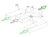
도1은 본 발명의 일 실시예에 따른 마이크로 믹서의 개념을 나타낸 사시도이다.1 is a perspective view showing the concept of a micro mixer according to an embodiment of the present invention.
도1에 도시된 바와 같이, 본 발명의 일 실시예에 따른 수직 적층식 마이크로 믹서는 혼합대상인 유체가 주입되는 주입채널(100), 유체의 혼합이 이루어지는 다수의 믹싱채널(200), 그리고 최종적으로 혼합된 유체가 배출되는 배출채널(300)을 포함하여 이루어진다.As shown in FIG. 1, the vertically stacked micro mixer according to an embodiment of the present invention includes an
주입채널(100)은 2개의 주입구를 구비하여 제1, 제2 주입구(101,102)에는 시료와 시약에 해당하는 각각의 서로 다른 유체가 주입되며, 그 중에서 제2 주입구(102)는 후술하는 첫 번째 믹싱채널의 유입구(211)와 바로 연결되며, 제1 주입구(101)는 "ㅁ"자 형상의 분리유로(110)와 연결된다.The
따라서, 제1 주입구(101)를 통하여 주입된 제2 유체(시약 또는 시료)는 동일한 유량으로 분리된 후에 다시 합류된다. 이때, 제2 유체가 합류되는 각도는 유체 흐름의 진행방향에 대하여 비스듬한 방향으로 합류하는 것도 가능하지만, 유체의 보다 정확한 적층 및 혼합을 위하여 서로 정면으로 합류하는 것이 바람직하다.Therefore, the second fluid (reagent or sample) injected through the
또한, 분리유로(110)에서 좌우로 분리되는 부분도 서로 180ㅀ반대되는 방향으로 분리되는 것이 바람직 하지만, 비스듬한 각도로 분리되는 것도 가능하다.In addition, although the portions separated from the left and right in the
도2는 합류부에서의 적층과정을 나타낸 개념도이다.2 is a conceptual diagram illustrating a lamination process at a confluence unit.
전술한 분리유로(110)는 첫 번째 믹싱채널의 합류부(213)에서 믹싱채널(200) 과 연결되며, 이 과정에서 첫 번째 적층 혼합과정이 이루어진다.The above-described
도2를 참조하면, 분리유로(110)를 통과한 제2 유체(20)는 정면으로 다시 합류하면서 믹싱채널(200)의 합류부(213)를 통하여 믹싱채널(200)의 중앙유로(210)로 유입되고, 제2 주입구(102)를 통하여 유입된 제1 유체(10)는 제2 주입구(102)와 연통된 믹싱채널(200)의 중앙유로(210)를 통과하면서 합류부(213)에서 제2 유체(20)와 적층되는 것이다.Referring to FIG. 2, the
유체가 서로 합류되는 과정을 구체적으로 설명하면 다음과 같다.A process in which the fluids join each other will be described in detail as follows.
중앙유로(210)와 분리유로(110)는 서로 층을 달리하여 연결되며, 아래쪽에서 합류되는 제2 유체(20)가 상부로 이동하면서 상층의 제1 유체(10)와 적층되어 혼합된다. 마이크로 미터 단위의 채널 특성상 두 유체는 혼합과정에서 층류를 형성하고 그 결과, 제1 유체(10)와 제2 유체(20)는 두 개의 층을 이루는 형태로 혼합되어 혼합유체(30)가 된다.The
도3은 도1에 표시된 위치에서의 혼합상태를 표시한 단면도이다.3 is a cross-sectional view showing a mixed state at the position shown in FIG.
도3을 참조하면, 중앙유로를 통과하는 제1 유체(노란색으로 표시됨)에 분리유로를 통과하는 제2 유체(붉은색으로 표시됨)가 밀려 올라오면서 혼합되고, 합류부를 통과한 혼합유체는 수직방향으로 적층 되면서 제1 유체와 제2 유체가 층을 이루는 이층구조를 이룬다.Referring to FIG. 3, the first fluid (shown in yellow) passing through the central flow passage is mixed with the second fluid (shown in red) passing through the separation flow passage and mixed, and the mixed fluid passing through the confluence portion is vertical. Stacked to form a two-layer structure in which the first fluid and the second fluid layered.
이러한 혼합과정이 믹싱채널에서 반복되면서, 최종적으로 배출채널을 통하여 배출되는 최종혼합유체는 도3에 도시된 바와 같이, 여러 층을 이루는 혼합유체가 되며, 마이크로 믹서 내에 배열된 믹싱채널의 수에 따라 제1 유체와 제2 유체가 반 복적으로 적층된 구조를 이루게 된다.As this mixing process is repeated in the mixing channel, the final mixed fluid finally discharged through the discharge channel becomes a mixed fluid consisting of several layers, as shown in FIG. 3, depending on the number of mixing channels arranged in the micromixer. The first fluid and the second fluid are repeatedly stacked.
이와 같은 혼합과정이 반복적으로 이루어지는 믹싱채널은 중앙부를 관통하는 중앙유로와 주입채널의 분리유로와 마찬가지로 분리와 재결합을 담당하는 우회유로를 포함한다.The mixing channel, in which the mixing process is repeated, includes a bypass channel, which is responsible for separation and recombination, similarly to the central channel passing through the central portion and the separation channel of the injection channel.
도1에 도시된 바와 같이, 중앙유로(210)는 제1 유체가 유입되는 유입구(211), 제2 유체가 상기 제1 유체와 층을 달리하여 합류되어 수직으로 적층된 혼합유체를 형성하는 합류부(213), 상기 혼합유체의 유량의 일부가 좌우 동일한 양으로 분리되는 분리부(215), 상기 혼합유체의 유량의 나머지가 유출되는 유출구(217)를 포함하며, 우회유로(220)는 중앙유로(210)와 상기 분리부(215)에서 분리된 혼합유체가 다시 합류되도록 형성되는 것을 특징으로 한다.As shown in FIG. 1, the
도1을 참조하면, 다수의 믹싱채널(200)이 연속적으로 연결되고 있음을 알 수 있는데, 그 연결구조는 다음과 같다.Referring to FIG. 1, it can be seen that a plurality of mixing
즉, 믹싱채널의 유출구(217)는 다른 층에 위치하는 또 다른 믹싱채널의 유입구(211)와 연통되고, 합류부(213)에는 다른 층의 믹싱채널의 우회유로(220)가 상기 중앙유로(210)와 합류되도록 상기 믹싱채널이 반복적으로 구비되는 것이다.That is, the
주입채널 직후에 위치하는 첫 번째 믹싱채널은 전술한 바와 같이, 제1 유체와 제2 유체가 혼합되도록 첫 번째 믹싱채널의 유입구는 주입채널의 제2 주입구와 연통되고, 첫 번째 믹싱채널의 합류부에는 주입채널의 분리유로가 첫 번째 믹싱채널의 중앙유로와 합류된다.As described above, the first mixing channel located immediately after the injection channel is configured such that the inlet of the first mixing channel communicates with the second inlet of the injection channel so that the first fluid and the second fluid are mixed, and the confluence of the first mixing channel. The separation channel of the injection channel joins the central channel of the first mixing channel.
다음부터는 믹싱채널이 반복되면서 유체의 혼합이 이루어지는데, 첫 번째 믹 싱채널의 경우 서로 다른 종류에 해당하는 제1 유체와 제2 유체가 혼합되었지만, 두 번째 믹싱채널부터는 이미 혼합이 이루어져서 동일한 적층구조를 갖는 혼합유체가 제1 유체와 제2 유체로서 반복적인 분리와 재결합 과정을 거치게 된다.From then on, the mixing channel is repeated, and the fluid is mixed. In the first mixing channel, the first and second fluids of different types are mixed, but from the second mixing channel, the same stacking structure is already formed. The mixed fluid having the first fluid and the second fluid undergoes repeated separation and recombination processes.
믹싱채널(200) 말단에 연결되는 배출채널(300)은 믹싱채널(200)을 통하여 혼합된 제1 혼합유체가 유입되는 유입공(301), 제2 혼합유체가 제1 혼합유체와 층을 달리하여 합류되어 수직으로 적층된 최종혼합유체를 형성하는 혼합부(303), 최종혼합유체가 배출되는 배출공(305)을 포함한다.The
여기서 마지막 믹싱채널(200)의 유출구(217)는 배출채널(300)의 유입공(301)과 연통되고, 배출채널의 혼합부(303)에는 마지막 믹싱채널의 우회유로(220)가 배출채널과 합류된다.Here, the
즉, 상기 제2 유체는 상기 제1 유체의 흐름에 대하여 수직한 양 방향으로 층을 달리하여 상기 합류부(213)에서 합류되고, 상기 제2 혼합유체는 상기 제1 혼합유체의 흐름에 대하여 수직한 양 방향으로 층을 달리하여 상기 혼합부(303)에서 합류되는 것이다.That is, the second fluid is joined at the
믹싱채널 중앙유로(210)의 분리부(215)에서 분리된 유체는 좌우에 구비된 우회유로(220)를 통하여 다음 믹싱채널의 합류부로 이동하는데, 이 경우 우회유로(220)로 흐르는 유체의 유량과 중앙유로(210)를 통하여 유출구로 배출되는 유량은 서로 동일한 양을 이루게 된다.The fluid separated in the
즉, 믹싱채널의 합류부(213)에서 혼합된 유체가 양분되어 절반은 유출구(217)를 통하여 다음 믹싱채널로 이동하고, 나머지 절반은 우회유로(220)를 통하 여 다음 믹싱채널의 합류부로 이동하여 다시 유출구를 통과한 유체와 합류하는 것이다.That is, the mixed fluid at the
따라서, 중앙유로와 우회유로의 길이가 결정되면 그에 따른 유로의 폭을 결정할 수 있게 된다.Therefore, when the length of the central channel and the bypass channel is determined, the width of the channel can be determined accordingly.
이 때, 우회유로의 채널 너비(W2)는 다음과 같이 결정할 수 있다.At this time, the channel widthW2 of the bypass flow path may be determined as follows.

이 때,


여기에서,H는 채널의 높이이다.WhereH is the height of the channel.
분리부에서 분리되는 우회유로(220)의 중앙유로(210)에 대한 분리 각도는 다양한 각도가 가능하며, 본 발명은 특정 각도에 한정되지 않는다. 그 중 도1은 표현의 편의상 우회유로(220)가 중앙유로(210)에 대하여 수직한 방향으로 분리되는 예를 도시하고 있다.Separation angles for the
이와 같이, 상층과 하층으로 양분 가능한 마이크로 믹서에서, 주입채널, 다수 각각의 믹싱채널, 그리고 배출채널이 상층과 하층, 2개 층에 번갈아가면서 위치하도록 연결되어, 혼합대상인 유체가 상층과 하층을 번갈아 가면서 유입되는 것이 다.In this way, in the micromixer which is divided into upper and lower layers, the injection channel, each of the mixing channels, and the discharge channel are alternately positioned in two layers, the upper and lower layers, and the fluid to be mixed alternately in the upper and lower layers. It flows in as it goes.
혼합과정은 합류부와 혼합부에서 서로 교차하는 유로 사이에서 이루어지는데, 이때 합류부와 혼합부를 통과하는 부분만 유로의 폭을 감소시켜서, 상대적인 높이 대 너비의 비를 높여 유속을 빠르게 함으로써, 혼합을 촉진시킬 수 있으며, 채널 너비가 전반적으로 넓기 때문에 압력을 낮추어주는 장점을 가지게 된다.The mixing process is carried out between flow paths intersecting with each other at the confluence and the mixing part. At this time, only the part passing through the confluence part and the mixing part reduces the width of the flow path, thereby increasing the flow rate by increasing the ratio of the relative height to the width to speed up the mixing. It has the advantage of lowering the pressure because of the wide overall channel width.
도4는 본 발명의 다른 실시예인 유로의 폭이 감소된 경우를 도시한 사시도이다. 도4에 도시된 바와 같이, 중앙유로(210), 그리고 중앙유로(210)와 만나는 우회유로(220) 및 분리유로(미도시)의 폭을 줄여줌으로써 혼합과정을 촉진 시킬 수 있다.4 is a perspective view illustrating a case in which a width of a flow path, which is another embodiment of the present invention, is reduced. As shown in FIG. 4, the mixing process may be promoted by reducing the width of the
이 경우, 합류부(213)와 혼합부(미도시)를 통과하는 유로의 폭과 깊이의 비가 적어도 4 인 것이 바람직하다. 즉, 도4에서 W와 Ht의 비율이 1:4 이상인 것을 의미한다.In this case, it is preferable that the ratio of the width and depth of the flow path passing through the
도5는 본 발명의 실시예인 수직 적층식 마이크로 믹서의 효과적인 혼합여부를 증명하기 위하여 수행된 전산유체역학(Computational Fluid Dynamics, CFD)의 수치해석 결과를 나타낸 도면이다.5 is a view showing the numerical results of Computational Fluid Dynamics (CFD) performed to prove the effective mixing of the vertically stacked micro mixer is an embodiment of the present invention.
도5를 참조하면, 양방향에서 유체가 유입되면서 이루어지는 혼합과정을 거치면서 최초 유입유체들이 점점 혼합됨을 알 수 있다.Referring to Figure 5, it can be seen that the first inlet fluid is gradually mixed while the mixing process is made while the fluid is introduced in both directions.
이때, Schㆆnfeld 등의 연구에서 보여지듯이 재결합 구간에서 분리 벽이 존재하지 않을 경우 도3에서와 같은 이상적인 적층은 기대하기 어렵지만, 본 실시예에 따른 마이크로 믹서는 합류부와 혼합부에서 수직으로 적층되어 혼합될 유체가 양쪽에서 균일하게 유입됨에 따라 결과적으로 도3에서 보인 이상적인 적층을 이루어낼 수 있게 된다.At this time, as shown in the Sch ㆆ nfeld et al., When there is no separation wall in the recombination section, ideal stacking as shown in FIG. 3 is difficult to expect, but the micromixer according to the present embodiment is stacked vertically at the joining and mixing sections. As a result, the fluid to be mixed flows uniformly from both sides, resulting in the ideal lamination shown in FIG.
특히, 유체가 층을 달리하여 일방에서 유입되는 경우와 비교하여, 안정적인 적층구조를 이루어낸다. 즉, 일방에서만 유체가 유입되는 경우에는 유입되어 층을 이루는 유체가 한쪽으로 치우치는 문제점이 발생할 수 있으나, 본 발명의 실시예인 수직 적층식 마이크로 믹서의 경우, 유체의 치우침이 방지되어 안정적인 적층이 가능하여 진다.In particular, compared to the case where the fluid is introduced from one side in a different layer, a stable laminated structure is achieved. That is, when the fluid is introduced in only one side, a problem may arise that the inflow and layered fluid are biased to one side, but in the vertically stacked micro mixer according to the embodiment of the present invention, the liquid is prevented from being biased and thus stable lamination is possible. Lose.
이와 같이 본 실시예에 따른 마이크로 믹서는 분리 벽이 없이도 이상적인 적층을 유도하게 되어, 두 유체간의 경계 면을 기하 급수적으로 늘려 보다 효과적인 적층식 혼합을 야기하게 된다. 특히 분리 벽이 존재하지 않아 사출 성형 등의 대량 생산 방법을 통해 저렴한 가격에 제조가 가능해지는 장점을 갖는다.As such, the micromixer according to the present embodiment induces an ideal lamination even without a separating wall, thereby increasing the interface between the two fluids exponentially, leading to more effective laminated mixing. In particular, there is no separation wall has the advantage that can be manufactured at a low price through a mass production method such as injection molding.
또한 일반적인 MEMS 공정을 통해 제작되는 일반적인 사각 단면을 가지는 마이크로 채널들이 가지는 특징인, 채널의 너비가 두께보다 상당히 큰 형상에 대해, 본 실시예에 따른 마이크로 믹서는 얇은 방향인 두께 방향으로 적층을 유도하여 유체의 확산 길이를 보다 효과적으로 줄이는 큰 장점을 가진다.In addition, the micromixer according to the present embodiment induces lamination in a thin direction in a thickness direction for a shape in which the width of the channel is significantly larger than the thickness, which is characteristic of microchannels having a general rectangular cross section manufactured through a general MEMS process. This has the great advantage of reducing the diffusion length of the fluid more effectively.
마지막으로 본 실시예에 따른 마이크로 믹서의 연속적으로 배열된 믹싱채널들은 유입되어 분할된 유체의 유동 진로 길이를 동일하게 하여 혼합이 전혀 일어나지 않는 부분을 없앨 수 있는 장점 또한 가지고 있다.Finally, the continuously arranged mixing channels of the micromixer according to the present embodiment also have the advantage that the mixing path length of the inflowed and divided fluids can be the same to eliminate the portion where mixing does not occur at all.
한편, 도 6 내지 도 8은 본 발명의 일 실시예에 따른 수직 적층식 마이크로 믹서의 제조방법, 특히 사출 성형 등의 대량 생산을 통한 제조방법을 이용하여 믹 싱채널을 순차적으로 제조하는 공정을 나타낸 평면도와 단면도로 이루어진 공정 순서도이다.On the other hand, Figures 6 to 8 illustrate a process for manufacturing a mixing channel sequentially using a manufacturing method of a vertically stacked micro mixer according to an embodiment of the present invention, in particular, a manufacturing method through mass production such as injection molding. Process flow chart consisting of a plan view and a cross-sectional view.
도6 내지 도8에 도시된 바와 같이, 본 발명의 수직 적층식 마이크로 믹서를 제조하는 방법은 전술한 수직 적층식 마이크로 믹서를 형성하는 상판과 하판에 주입채널, 다수의 믹싱채널, 및 배출채널의 형상을 갖는 홈이 번갈아서 형성되도록 상판과 하판을 제조하는 판 제조단계(도6, 도7) 및 상기 상판과 하판을 맞대어 접합하는 접합단계(도8)를 포함한다.As shown in Figures 6 to 8, the method for manufacturing a vertically stacked micro mixer of the present invention is the upper and lower plates forming the vertically stacked micro mixer described above of the injection channel, a plurality of mixing channels, and the discharge channel The plate manufacturing step (Fig. 6, 7) for manufacturing the upper plate and the lower plate so that the grooves having a shape alternately formed, and the bonding step for bonding the upper plate and the lower plate to each other (Fig. 8).
먼저, 도6과 도7은 각각 본 실시예에 따른 수직 적층식 마이크로 믹서의 상판 및 하판의 제조 과정을 순차적으로 보여준다. 하단의 단면도는 상단의 평면도에서 K-K'부와 J-J'부의 단면도이다.First, Figures 6 and 7 sequentially show the manufacturing process of the upper and lower plates of the vertically stacked micro mixer according to the present embodiment, respectively. The cross-sectional view of the bottom is a cross-sectional view of the K-K 'part and the J-J' part in the top plan view.
판 제조단계는 채널의 형상을 갖는 금형인서트를 형성하는 인서트 형성단계와 금형인서트에 폴리머를 몰딩하는 몰딩단계, 및 몰딩단계에서 몰딩한 폴리머를 취출하는 취출단계를 포함한다.The plate manufacturing step includes an insert forming step of forming a mold insert having a channel shape, a molding step of molding a polymer on the mold insert, and a takeout step of taking out the polymer molded in the molding step.
인서트 형성단계는 도6에서 (a) ~ (c)단계로 이루어진다.The insert forming step consists of the steps (a) to (c) in FIG.
우선 기판(50), 예를 들어, 니켈 금속 기판을 표면 세척 공정을 통해 세척한 후, 도6의 (a)단계에서와 같이 감광재(41), 예를 들어 SU-8 등을 도포하여 믹싱채널의 유로를 이루는 공간(40)을 일반적인 자외선 사진 식각 공정 등을 통해 형성한다.First, the
다음으로, (b)단계에 도시된 바와 같이 전기도금(electroplating) 혹은 전주 (electroforming) 등의 과정을 통해 믹싱채널의 유로를 이루는 공간(40)에 니켈, 구리 등의 금속(42)을 형성한다.Next, as shown in step (b), a
다음으로, (c)단계와 같이 형성되어 있는 SU-8 등의 감광재(41)를 식각 등의 공정을 통해 없애면, 본 실시예에 따른 마이크로 믹서의 상판 제조를 위한 금형 인서트(45)를 형성할 수 있다.Next, if the
몰딩단계는 도6의 d 단계에 해당하는 것으로, 도6의 (d)에 도시된 바와 같이 사출 성형, 핫 엠보싱(hot embossing), UV-몰딩, 주조 등의 대량 생산 방법을 통해 폴리머(43)를 몰딩한다. 이 때, 폴리머(43)는 (열)가소성 또는 (열, UV)경화성 폴리머 수지가 적용될 수 있으며, 일례로 환형 올레핀 공중합체(cyclic olefin copolymer, COC), 폴리메틸 메타크릴레이트(polymethylmethacrylate, PMMA), 폴리스틸렌(polystyrene, PS), 폴리카보네이트(polycarbonate, PC), 폴리디메틸 실록산(polydimethylsiloxane, PDMS), 폴리테트라플루오르에틸렌 불소수지(polytetrafluoroethylene, Teflon), 폴리염화비닐(polyvinylchloride, PVC) 등의 폴리머(43)를 몰딩할 수 있다.The molding step corresponds to step d of FIG. 6, and the
이제 몰딩한 폴리머(43)를 취출하는 취출단계를 통하여, 도6의 (e)에서 보는 바와 같이, 본 실시예에 따른 마이크로 믹서의 상판(44)을 얻을 수 있다.Now, as shown in Fig. 6E, through the extraction step of taking out the molded
마찬가지 방법을 하판에 적용하면, 도7에 도시된 것과 같은 하판(64)을 얻을 수 있으며, 하판(64)의 홈과 상판(44)의 홈이 서로 마주보도록 상판과 하판을 맞대고 접합단계를 실시하면 원하는 마이크로 믹서를 얻게된다.When the same method is applied to the lower plate, a
도8은 본 실시예에 따른 수직 적층식 마이크로 믹서의 상,하판 접합결과를 나타낸 개념도이고, 하단의 단면도는 상단의 평면도에서 L-L'부의 단면도이다.8 is a conceptual view showing a result of joining the upper and lower plates of the vertically stacked micro mixer according to the present embodiment, and a cross-sectional view of the lower part is a cross-sectional view of the L-L 'portion in the top plan view.
즉, 도8에 도시된 바와 같이 열 접합(thermal bonding), 본드 물질을 통한 접합, 박판 접합(lamination), 초음파 접합 등의 접합 방법 등을 통해 본 실시예에 따른 수직 적층식 마이크로 믹서의 제조를 위한 상판(44)과 하판(64)을 접합하면 마이크로 믹서를 제작할 수 있다.That is, as shown in FIG. 8, the manufacture of the vertically stacked micromixer according to the present embodiment is performed through a bonding method such as thermal bonding, bonding through a bond material, lamination, ultrasonic bonding, or the like. When the
도8을 참조하면, 연속적으로 연결되는 믹싱채널의 중앙유로(210a, 210b)가 층을 달리하며 연결되며, 상판(44)의 우회유로(213a)가 하판(64)의 중앙유로(210b)와 합류부에서 다시 만나는 것을 확인할 수 있다.Referring to FIG. 8, the
한편, 본 발명의 실시예에 따른 마이크로 믹서의 제조방법에서 인서트 형성단계는 마이크로 밀링공정 등의 정밀성형 공정을 통하여 인서트를 직접 형성하거나, 또는 기판 위에 감광재를 패터닝하여 금형인서트로 사용하는 것이 가능하다.On the other hand, in the method of manufacturing a micro mixer according to an embodiment of the present invention, the insert forming step may be used as a mold insert by directly forming an insert through a precision molding process such as a micro milling process or by patterning a photosensitive material on a substrate. Do.
뿐만 아니라, 판 제조단계에서 몰딩기법을 사용하지 않고, 정밀성형 공정을 통해 상판 및 하판을 이루는 폴리머 또는 금속에 채널의 형상을 갖는 홈을 직접 형성하는 것도 가능하며, 상판 및 하판을 바로 식각하여 채널의 형상을 갖는 홈을 직접 형성하는 것도 가능하다.In addition, without using a molding method in the plate manufacturing step, it is possible to directly form the grooves having the shape of the channel in the polymer or metal constituting the upper plate and the lower plate through the precision molding process, by directly etching the upper plate and the lower plate It is also possible to form a groove having a shape of directly.
이상에서 설명한 것은 본 발명에 따른 수직 적층식 마이크로 믹서 및 그 제조방법를 실시하기 위한 하나의 실시예에 불과한 것으로서, 본 발명은 상기한 실시예에 한정되지 않고, 이하의 특허청구범위에서 청구하는 바와 같이 본 발명의 요지를 벗어남이 없이 당해 발명이 속하는 분야에서 통상의 지식을 가진 자라면 누구든지 다양한 변경실시가 가능한 범위까지 본 발명의 기술적 정신이 있다고 할 것이다.What has been described above is just one embodiment for carrying out the vertically stacked micro-mixer according to the present invention and a manufacturing method thereof, and the present invention is not limited to the above-described embodiment, as claimed in the following claims. Without departing from the gist of the present invention, anyone of ordinary skill in the art will have the technical spirit of the present invention to the extent that various changes can be made.
도1은 본 발명의 실시예에 따른 마이크로 믹서의 개념을 나타낸 사시도,1 is a perspective view showing the concept of a micro mixer according to an embodiment of the present invention;
도2는 합류부에서의 적층과정을 나타낸 개념도,2 is a conceptual diagram showing a lamination process at a confluence unit;
도3은 도1에 표시된 위치에서의 혼합상태를 표시한 단면도,3 is a sectional view showing a mixed state at the position shown in FIG. 1;
도4는 본 발명의 다른 실시예인 유로의 폭이 감소된 경우를 도시한 사시도,4 is a perspective view showing a case in which the width of the flow path is reduced according to another embodiment of the present invention;
도5는 본 발명의 실시예인 수직 적층식 마이크로 믹서의 효과적인 혼합여부를 증명하기 위하여 수행된 수치해석 결과를 나타낸 도면,Figure 5 is a view showing the numerical analysis results performed to prove the effective mixing of the vertically stacked micro mixer is an embodiment of the present invention,
도6은 상판의 제조방법을 나타낸 공정순서도,6 is a process flowchart showing a manufacturing method of the upper plate;
도7은 하판의 제조방법을 나타낸 공정순서도,7 is a process flowchart showing the manufacturing method of the lower plate;
도8은 상판과 하판의 접합방법을 나타낸 도면이다.8 is a view showing a bonding method of the upper plate and the lower plate.
<도면의 부호에 대한 간단한 설명><Short description of the symbols in the drawings>
100: 주입채널101: 제1 주입구100: injection channel 101: the first injection hole
102: 제2 주입구110: 분리유로102: second injection port 110: separation flow path
200: 믹싱채널210: 중앙유로200: mixing channel 210: central euro
211: 유입구213: 합류부211: inlet 213: confluence
215: 분리부217: 유출구215: separator 217: outlet
220: 우회유로300: 배출채널220: bypass flow path 300: discharge channel
301: 유입공303: 혼합부301: inlet hole 303: mixing unit
305: 배출공305: discharge hole
Claims (17)
Translated fromKoreanPriority Applications (1)
| Application Number | Priority Date | Filing Date | Title |
|---|---|---|---|
| KR1020080014408AKR101113727B1 (en) | 2008-02-18 | 2008-02-18 | Vertical lamination micromixer |
Applications Claiming Priority (1)
| Application Number | Priority Date | Filing Date | Title |
|---|---|---|---|
| KR1020080014408AKR101113727B1 (en) | 2008-02-18 | 2008-02-18 | Vertical lamination micromixer |
Publications (2)
| Publication Number | Publication Date |
|---|---|
| KR20090089065A KR20090089065A (en) | 2009-08-21 |
| KR101113727B1true KR101113727B1 (en) | 2012-02-27 |
Family
ID=41207429
Family Applications (1)
| Application Number | Title | Priority Date | Filing Date |
|---|---|---|---|
| KR1020080014408AExpired - Fee RelatedKR101113727B1 (en) | 2008-02-18 | 2008-02-18 | Vertical lamination micromixer |
Country Status (1)
| Country | Link |
|---|---|
| KR (1) | KR101113727B1 (en) |
Cited By (1)
| Publication number | Priority date | Publication date | Assignee | Title |
|---|---|---|---|---|
| KR101389369B1 (en) | 2012-07-27 | 2014-04-29 | 한국과학기술원 | Microfluidic Floating Block, Microfluidic Sealing Block, and An Combining Method of Microfluidic Floating Device by Using These |
Families Citing this family (6)
| Publication number | Priority date | Publication date | Assignee | Title |
|---|---|---|---|---|
| KR101432729B1 (en)* | 2012-12-24 | 2014-08-21 | 인하대학교 산학협력단 | Micromixer with circular chambers and crossing constriction channels |
| KR20150105856A (en)* | 2014-03-10 | 2015-09-18 | 연세대학교 산학협력단 | Micro Mixer Using Taylor Gortler Vortex and Manufacturing Method Thereof |
| KR102114779B1 (en)* | 2019-01-31 | 2020-05-25 | 인하대학교 산학협력단 | Micromixer |
| CN110732275B (en)* | 2019-10-15 | 2024-10-29 | 武夷学院 | Laminated passive micro-mixer and manufacturing method thereof |
| EP4198119A1 (en)* | 2021-12-16 | 2023-06-21 | Institute of Solid State Physics, University of Latvia | A microfluidic device for simulating organ functions |
| CN118846861B (en)* | 2024-09-18 | 2025-02-18 | 南昌航空大学 | A self-driving micro-hybrid chip |
Citations (4)
| Publication number | Priority date | Publication date | Assignee | Title |
|---|---|---|---|---|
| KR20010024538A (en)* | 1997-10-22 | 2001-03-26 | 플레믹 크리스티안 | Micromixer |
| JP2004113967A (en) | 2002-09-27 | 2004-04-15 | Fuji Electric Systems Co Ltd | Micro mixer |
| JP2006102681A (en) | 2004-10-07 | 2006-04-20 | Hitachi Ltd | Fluid mixer and microreactor system |
| KR100658361B1 (en) | 2005-09-12 | 2006-12-15 | 주식회사 스펙 | Micro channel reactor |
- 2008
- 2008-02-18KRKR1020080014408Apatent/KR101113727B1/ennot_activeExpired - Fee Related
Patent Citations (4)
| Publication number | Priority date | Publication date | Assignee | Title |
|---|---|---|---|---|
| KR20010024538A (en)* | 1997-10-22 | 2001-03-26 | 플레믹 크리스티안 | Micromixer |
| JP2004113967A (en) | 2002-09-27 | 2004-04-15 | Fuji Electric Systems Co Ltd | Micro mixer |
| JP2006102681A (en) | 2004-10-07 | 2006-04-20 | Hitachi Ltd | Fluid mixer and microreactor system |
| KR100658361B1 (en) | 2005-09-12 | 2006-12-15 | 주식회사 스펙 | Micro channel reactor |
Cited By (1)
| Publication number | Priority date | Publication date | Assignee | Title |
|---|---|---|---|---|
| KR101389369B1 (en) | 2012-07-27 | 2014-04-29 | 한국과학기술원 | Microfluidic Floating Block, Microfluidic Sealing Block, and An Combining Method of Microfluidic Floating Device by Using These |
Also Published As
| Publication number | Publication date |
|---|---|
| KR20090089065A (en) | 2009-08-21 |
Similar Documents
| Publication | Publication Date | Title |
|---|---|---|
| Kim et al. | A serpentine laminating micromixer combining splitting/recombination and advection | |
| US6676835B2 (en) | Microfluidic separators | |
| Kim et al. | Disposable integrated microfluidic biochip for blood typing by plastic microinjection moulding | |
| Oh et al. | Design of pressure-driven microfluidic networks using electric circuit analogy | |
| CN103946548B (en) | There is the microfluidic device of deformable valve | |
| Sivashankar et al. | A “twisted” microfluidic mixer suitable for a wide range of flow rate applications | |
| KR101113727B1 (en) | Vertical lamination micromixer | |
| US7718420B2 (en) | Microfluidic biochip for blood typing based on agglutination reaction | |
| KR100764022B1 (en) | Microfluidic biochips for blood type diagnosis based on aggregation reaction | |
| US20040109793A1 (en) | Three-dimensional microfluidics incorporating passive fluid control structures | |
| WO2003052428A1 (en) | Three-dimensional microfluidics incorporating passive fluid control structures | |
| EP1386169A1 (en) | Three-dimensional microfluidics incorporating passive fluid control structures | |
| KR101541458B1 (en) | Fluid mixing method and fluid mixing apparatus | |
| KR100666500B1 (en) | Spiral Lamination Chaos Micro Mixer | |
| KR20210108754A (en) | Microfluidic mixer and method of mixing fluid using the same | |
| Lee et al. | Accurate, predictable, repeatable micro-assembly technology for polymer, microfluidic modules | |
| KR20150105856A (en) | Micro Mixer Using Taylor Gortler Vortex and Manufacturing Method Thereof | |
| CN102500266B (en) | Quick micro-mixing device for high-viscosity solution | |
| KR101515403B1 (en) | Microfluidic Channel Using Hook-Shaped Structures, Manufacturing Method Thereof, and Analysis System Having the Same | |
| KR101176175B1 (en) | Micro mixer and method for fabricating thereof | |
| KR100967414B1 (en) | Microfluidic control device for fluid droplet mixing and method for mixing fluid droplets using the same | |
| CN107469745A (en) | A kind of micro-fluidic combinatorial chemistry reaction chip | |
| Attia et al. | Integration of functionality into polymer-based microfluidic devices produced by high-volume micro-moulding techniques | |
| Liu et al. | Development of integrated microfluidic system for genetic analysis | |
| D Leonida et al. | Microfluidics: from engineering to life sciences |
Legal Events
| Date | Code | Title | Description |
|---|---|---|---|
| PA0109 | Patent application | St.27 status event code:A-0-1-A10-A12-nap-PA0109 | |
| PG1501 | Laying open of application | St.27 status event code:A-1-1-Q10-Q12-nap-PG1501 | |
| A201 | Request for examination | ||
| PA0201 | Request for examination | St.27 status event code:A-1-2-D10-D11-exm-PA0201 | |
| D13-X000 | Search requested | St.27 status event code:A-1-2-D10-D13-srh-X000 | |
| D14-X000 | Search report completed | St.27 status event code:A-1-2-D10-D14-srh-X000 | |
| PE0902 | Notice of grounds for rejection | St.27 status event code:A-1-2-D10-D21-exm-PE0902 | |
| P11-X000 | Amendment of application requested | St.27 status event code:A-2-2-P10-P11-nap-X000 | |
| P13-X000 | Application amended | St.27 status event code:A-2-2-P10-P13-nap-X000 | |
| E701 | Decision to grant or registration of patent right | ||
| PE0701 | Decision of registration | St.27 status event code:A-1-2-D10-D22-exm-PE0701 | |
| GRNT | Written decision to grant | ||
| PR0701 | Registration of establishment | St.27 status event code:A-2-4-F10-F11-exm-PR0701 | |
| PR1002 | Payment of registration fee | St.27 status event code:A-2-2-U10-U11-oth-PR1002 Fee payment year number:1 | |
| PG1601 | Publication of registration | St.27 status event code:A-4-4-Q10-Q13-nap-PG1601 | |
| LAPS | Lapse due to unpaid annual fee | ||
| PC1903 | Unpaid annual fee | St.27 status event code:A-4-4-U10-U13-oth-PC1903 Not in force date:20150202 Payment event data comment text:Termination Category : DEFAULT_OF_REGISTRATION_FEE | |
| PC1903 | Unpaid annual fee | St.27 status event code:N-4-6-H10-H13-oth-PC1903 Ip right cessation event data comment text:Termination Category : DEFAULT_OF_REGISTRATION_FEE Not in force date:20150202 | |
| P22-X000 | Classification modified | St.27 status event code:A-4-4-P10-P22-nap-X000 | |
| P22-X000 | Classification modified | St.27 status event code:A-4-4-P10-P22-nap-X000 |