KR101113268B1 - System for generating power using piezoelectric element - Google Patents
System for generating power using piezoelectric elementDownload PDFInfo
- Publication number
- KR101113268B1 KR101113268B1KR1020090107121AKR20090107121AKR101113268B1KR 101113268 B1KR101113268 B1KR 101113268B1KR 1020090107121 AKR1020090107121 AKR 1020090107121AKR 20090107121 AKR20090107121 AKR 20090107121AKR 101113268 B1KR101113268 B1KR 101113268B1
- Authority
- KR
- South Korea
- Prior art keywords
- piezoelectric element
- electrical energy
- voltage
- energy
- power generation
- Prior art date
- Legal status (The legal status is an assumption and is not a legal conclusion. Google has not performed a legal analysis and makes no representation as to the accuracy of the status listed.)
- Expired - Fee Related
Links
Images


Classifications
- H—ELECTRICITY
- H02—GENERATION; CONVERSION OR DISTRIBUTION OF ELECTRIC POWER
- H02N—ELECTRIC MACHINES NOT OTHERWISE PROVIDED FOR
- H02N2/00—Electric machines in general using piezoelectric effect, electrostriction or magnetostriction
- H02N2/18—Electric machines in general using piezoelectric effect, electrostriction or magnetostriction producing electrical output from mechanical input, e.g. generators
- H02N2/185—Electric machines in general using piezoelectric effect, electrostriction or magnetostriction producing electrical output from mechanical input, e.g. generators using fluid streams
- H—ELECTRICITY
- H02—GENERATION; CONVERSION OR DISTRIBUTION OF ELECTRIC POWER
- H02J—CIRCUIT ARRANGEMENTS OR SYSTEMS FOR SUPPLYING OR DISTRIBUTING ELECTRIC POWER; SYSTEMS FOR STORING ELECTRIC ENERGY
- H02J7/00—Circuit arrangements for charging or depolarising batteries or for supplying loads from batteries
- H02J7/007—Regulation of charging or discharging current or voltage
- H—ELECTRICITY
- H02—GENERATION; CONVERSION OR DISTRIBUTION OF ELECTRIC POWER
- H02J—CIRCUIT ARRANGEMENTS OR SYSTEMS FOR SUPPLYING OR DISTRIBUTING ELECTRIC POWER; SYSTEMS FOR STORING ELECTRIC ENERGY
- H02J7/00—Circuit arrangements for charging or depolarising batteries or for supplying loads from batteries
- H02J7/34—Parallel operation in networks using both storage and other DC sources, e.g. providing buffering
- H02J7/342—The other DC source being a battery actively interacting with the first one, i.e. battery to battery charging
- H—ELECTRICITY
- H10—SEMICONDUCTOR DEVICES; ELECTRIC SOLID-STATE DEVICES NOT OTHERWISE PROVIDED FOR
- H10N—ELECTRIC SOLID-STATE DEVICES NOT OTHERWISE PROVIDED FOR
- H10N30/00—Piezoelectric or electrostrictive devices
- H10N30/30—Piezoelectric or electrostrictive devices with mechanical input and electrical output, e.g. functioning as generators or sensors
Landscapes
- Engineering & Computer Science (AREA)
- Power Engineering (AREA)
- General Electrical Machinery Utilizing Piezoelectricity, Electrostriction Or Magnetostriction (AREA)
Abstract
Translated fromKoreanDescription
Translated fromKorean본 발명은 압전소자를 이용한 전력 발전 시스템에 관한 것이다.The present invention relates to a power generation system using a piezoelectric element.
일반적으로, 전력발전소는 전지역에 걸쳐 가정집 또는 사무실등의 건축물 내부에 제공된 부하에 전력을 공급하도록 제공되었다.In general, power plants have been provided to power loads provided inside buildings such as homes or offices throughout the region.
그러나, 종래 전력발전소를 통해 공급되는 방법은 전지역에 걸쳐 건축물 내부에 제공된 부하에 전력을 지속적으로 공급해야하므로, 전력이 낭비되는 문제점이 있었고 자원이 고갈될 수가 있어 환경오염의 악화를 더욱 부추기는 문제점이 있었다.However, the method of supplying power through a conventional power plant has to continuously supply electric power to the load provided inside the building throughout the region, so there is a problem that power is wasted and resources can be depleted, thereby further exacerbating environmental pollution. There was this.
따라서, 최근에는 전력낭비를 줄이고 자원이 고갈되는 것을 방지하여 환경오염의 악화를 방지할 수 있는 개선된 전력 발전 시스템이 연구되어 오고 있다.Therefore, in recent years, improved power generation systems have been researched to reduce the waste of power and prevent the depletion of resources, thereby preventing environmental degradation.
본 발명의 목적은, 압전 소자에 의해 생성되는 전기 에너지를 인근 주변의 부하에 공급할 수가 있으므로, 전력낭비를 줄일 수가 있고 자원이 고갈되는 것을 방지할 수가 있어 환경오염의 악화를 방지할 수가 있는 압전소자를 이용한 전력 발전 시스템을 제공하는 데에 있다.An object of the present invention is to supply electrical energy generated by a piezoelectric element to a nearby load, so that the power consumption can be reduced and resources can be prevented from being depleted, thereby preventing the deterioration of environmental pollution. It is to provide a power generation system using.
본 발명의 다른 목적은, 압전 소자에 의해 생성되는 전기 에너지를 회수하고, 전지역에 걸쳐 가정집 또는 사무실 등의 건축물 내부에 제공된 부하에 회수된 전기 에너지로 상용 전원을 공급할 수가 있으므로, 전력낭비를 더욱 줄일 수가 있고 자원이 고갈되는 것을 더욱 방지할 수가 있어 환경오염의 악화를 더욱 방지할 수가 있는 압전소자를 이용한 전력 발전 시스템을 제공하는 데에 있다.Another object of the present invention is to recover the electrical energy generated by the piezoelectric element, and can supply commercial power with the electrical energy recovered to the load provided inside the building such as a home or office throughout the entire area, further reducing power consumption. The present invention provides a power generation system using a piezoelectric element that can prevent the depletion of resources and the exhaustion of resources, and further prevent the deterioration of environmental pollution.
본 발명의 또 다른 목적은, 장소에 구애받지 않고 에너지 축적 장치에 축적된 전기 에너지로 충전이 필요한 외부 기기를 충전시킬 수가 있어, 충전의 편리성을 향상시킬 수가 있는 압전소자를 이용한 전력 발전 시스템을 제공하는 데에 있다.Still another object of the present invention is to provide a power generation system using a piezoelectric element that can charge an external device that needs to be charged with electric energy accumulated in an energy storage device regardless of a place, and can improve the convenience of charging. To provide.
이러한 목적을 달성하기 위하여 본 발명은 대상 장소의 바닥면에 제공되어 외부 요인의 기계적인 압력에 의해 전기 에너지를 생산하는 적어도 하나의 압전 소자와, 대상 장소에 제공되어 적어도 하나의 압전 소자를 통해 생산된 전기 에너지를 축적하는 에너지 축적 장치, 및 대상 장소에 제공되어 에너지 축적 장치에 축적된 전기 에너지를 부하에 공급하는 에너지 공급 장치를 포함한다.In order to achieve this object, the present invention provides at least one piezoelectric element provided on the bottom surface of the target site to produce electrical energy by mechanical pressure of an external factor, and produced through the at least one piezoelectric element provided at the target site. And an energy supply device provided to the target place and supplying the electrical energy accumulated in the energy storage device to the load.
본 발명의 다른 특징에 따르면, 수중에 제공되어 흐르는 강물, 파도, 조류, 수압 등에 의한 압력에 의해 전기 에너지를 생산하는 적어도 하나의 압전 소자와, 수중에 제공되어 적어도 하나의 압전 소자를 통해 생산된 전기 에너지를 축적하는 에너지 축적 장치, 및 수중에 제공되어 에너지 축적 장치에 축적된 전기 에너지를 부하에 공급하는 에너지 공급 장치를 포함한다.According to another feature of the invention, at least one piezoelectric element for producing electrical energy by the pressure caused by flowing river water, waves, tides, hydraulic pressure, etc. provided in the water, and provided in the water produced through at least one piezoelectric element An energy storage device for accumulating electrical energy, and an energy supply device provided in the water to supply the electrical energy accumulated in the energy storage device to the load.
본 발명의 또 다른 특징에 따르면, 적어도 하나의 압전 소자는 둘 이상으로 제공되어 서로 전기적으로 연결되되, 서로 병렬 연결되거나 서로 직렬 연결된 것을 특징으로 한다.According to another feature of the invention, at least one piezoelectric element is provided in two or more are electrically connected to each other, it characterized in that they are connected in parallel or in series with each other.
본 발명의 또 다른 특징에 따르면, 에너지 축적 장치는 적어도 하나의 압전 소자의 출력단에 전기적으로 연결되어 적어도 하나의 압전 소자를 통해 생산되는 전기 에너지가 역류되는 것을 방지하도록 전기 에너지에 해당하는 전류를 정류시키는 정류 다이오드, 및 정류 다이오드를 통해 정류된 전류를 축적시키는 커패시터를 포함한다.According to another feature of the invention, the energy storage device is electrically connected to the output terminal of the at least one piezoelectric element to rectify a current corresponding to the electrical energy to prevent backflow of the electrical energy produced through the at least one piezoelectric element. And a capacitor for accumulating the rectified current through the rectifying diode.
본 발명의 또 다른 특징에 따르면, 부하는 직류 전압을 공급받거나 교류 전압을 공급받는 것을 특징으로 한다.According to another feature of the invention, the load is characterized in that the supply of a DC voltage or an AC voltage.
본 발명의 또 다른 특징에 따르면, 에너지 공급 장치는 에너지 축적 장치를 통해 축적된 전기 에너지에 해당하는 직류 전압을 공급받아 적정 레벨의 직류 전압으로 출력하여 부하에 적정 레벨의 직류 전압을 제공하는 직류 전압 레벨 변환 수단과, 에너지 축적 장치를 통해 축적된 전기 에너지에 해당하는 직류 전압을 공급받아 교류 전압으로 변환시키는 인버터와, 인버터를 통해 변환된 교류 전압을 적정 레벨의 교류 전압으로 출력하여 부하에 적정 레벨의 교류 전압을 제공하는 교류 전 압 레벨 변환 수단을 포함한다.According to another feature of the present invention, the energy supply device receives a DC voltage corresponding to the electrical energy accumulated through the energy storage device and outputs the DC voltage at an appropriate level to provide an appropriate DC voltage to the load. A level converting means, an inverter that receives a DC voltage corresponding to the electrical energy accumulated through the energy storage device and converts the AC voltage into an AC voltage, and outputs an AC voltage converted through the inverter as an AC voltage of an appropriate level to the load. AC voltage level converting means for providing an AC voltage.
본 발명의 또 다른 특징에 따르면, 에너지 축적 장치를 통해 축적된 직류 전압을 제공받아 전기 에너지를 회수하는 전력 공급소를 더 포함한다.According to another feature of the invention, it further comprises a power supply for recovering electrical energy by receiving the DC voltage accumulated through the energy storage device.
본 발명의 또 다른 특징에 따르면, 에너지 축적 장치와 선택적으로 연결되어 에너지 축적 장치에 축적된 전기 에너지로 외부 기기를 충전시키는 외부 충전 장치를 더 포함한다.According to another feature of the invention, it further comprises an external charging device that is selectively connected to the energy storage device to charge the external device with the electrical energy accumulated in the energy storage device.
본 발명의 또 다른 특징에 따르면, 대상 장소는 공항 활주로, 철로, 고속도로, 일반도로, 국도, 보도, 건물복도, 계단, 사무실, 거실, 나이트 클럽 스테이지등의 왕래가 많은 도로면 또는 건축물의 내부 바닥면중 적어도 하나의 장소인 것을 특징으로 한다.According to another feature of the invention, the target place is an airport runway, railroad, highway, general road, national road, sidewalk, building corridor, stairs, office, living room, night road, such as a busy road surface or the interior floor of the building At least one place of the surface is characterized in that.
상기한 바와 같이 이루어진 본 발명의 압전소자를 이용한 전력 발전 시스템에 따르면, 다음과 같은 효과를 얻을 수 있다.According to the power generation system using the piezoelectric element of the present invention made as described above, the following effects can be obtained.
첫째, 압전 소자에 의해 생성되는 전기 에너지를 인근 주변의 부하에 공급할 수가 있으므로, 전력낭비를 줄일 수가 있고 자원이 고갈되는 것을 방지할 수가 있어 환경오염의 악화를 방지할 수 있는 효과가 있다.First, since the electrical energy generated by the piezoelectric element can be supplied to a nearby load, power consumption can be reduced and resources can be prevented from being depleted, thereby preventing deterioration of environmental pollution.
둘째, 압전 소자에 의해 생성되는 전기 에너지를 회수하고, 전지역에 걸쳐 가정집 또는 사무실 등의 건축물 내부에 제공된 부하에 회수된 전기 에너지로 상용 전원을 공급할 수가 있으므로, 전력낭비를 더욱 줄일 수가 있고 자원이 고갈되는 것을 더욱 방지할 수가 있어 환경오염의 악화를 더욱 방지할 수 있는 다른 효과가 있다.Second, it is possible to recover the electric energy generated by the piezoelectric element and supply commercial power with the recovered electric energy to the load provided inside the buildings such as homes or offices throughout the region, further reducing power consumption and exhausting resources. There is another effect that can be further prevented to prevent further deterioration of environmental pollution.
셋째, 장소에 구애받지 않고 에너지 축적 장치에 축적된 전기 에너지로 충전이 필요한 외부 기기를 충전시킬 수가 있어, 충전의 편리성을 향상시킬 수 있는 또 다른 효과가 있다.Third, it is possible to charge the external device that needs to be charged by the electric energy accumulated in the energy storage device regardless of the place, there is another effect that can improve the convenience of charging.
이하에서는 첨부된 도면을 참고로 하여 본 발명의 바람직한 실시예들을 보다 상세히 설명하기로 한다.Hereinafter, with reference to the accompanying drawings will be described in detail preferred embodiments of the present invention.
<제 1 실시예><First Embodiment>
도 1은 본 발명의 제 1 실시예에 따른 압전소자를 이용한 전력 발전 시스템을 나타낸 블럭 구성도이고, 도 2는 본 발명의 제 1 실시예에 따른 압전소자를 이용한 전력 발전 시스템의 일예로써, 활주로에 압전 소자가 설치되어 전기 에너지를 생산하는 상태를 보여주기 위한 도면들이다.1 is a block diagram showing a power generation system using a piezoelectric element according to a first embodiment of the present invention, Figure 2 is an example of a power generation system using a piezoelectric element according to the first embodiment of the present invention, a runway The piezoelectric element is installed in the drawings for showing the state of producing electrical energy.
도 3은 본 발명의 제 1 실시예에 따른 압전소자를 이용한 전력 발전 시스템의 다른 일예로써, 철로에 압전 소자가 설치되어 전기 에너지를 생산하는 상태를 보여주기 위한 도면들이고, 도 4는 본 발명의 제 1 실시예에 따른 압전소자를 이용한 전력 발전 시스템의 또 다른 일예로써, 도로에 압전 소자가 설치되어 전기 에너지를 생산하는 상태를 보여주기 위한 도면들이다.3 is another example of a power generation system using a piezoelectric element according to a first embodiment of the present invention, the piezoelectric element is installed on the rail to show the state of producing electrical energy, Figure 4 is a view of the present invention As another example of the power generation system using the piezoelectric element according to the first embodiment, it is a view showing a state in which the piezoelectric element is installed on the road to produce electrical energy.
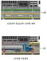
도 5는 본 발명의 제 1 실시예에 따른 압전소자를 이용한 전력 발전 시스템의 또 다른 일예로써, 지하철의 보도 블럭에 압전 소자가 설치되어 전기 에너지를 생산하는 상태를 보여주기 위한 도면들이고, 도 6a 내지 도 6c는 본 발명의 제 1 실시예에 따른 압전소자를 이용한 전력 발전 시스템의 또 다른 일예로써, 수중에 압전 소자가 설치되어 전기 에너지를 생산하는 상태를 보여주기 위한 도면들이다.5 is another example of a power generation system using a piezoelectric element according to a first embodiment of the present invention, the piezoelectric element is installed in the sidewalk block of the subway to show the state of producing electrical energy, Figure 6a 6C are still another example of the power generation system using the piezoelectric element according to the first embodiment of the present invention. The piezoelectric element is installed in water to show a state of producing electrical energy.
도 1 내지 도 6c를 참조하면, 본 발명의 제 1 실시예에 따른 압전소자를 이용한 전력 발전 시스템(100)은 적어도 하나의 압전 소자(102), 에너지 축적 장치(104), 에너지 공급 장치(106)등을 포함한다.1 to 6C, the
적어도 하나의 압전 소자(102)는 대상 장소의 바닥면에 제공되어 외부 요인의 기계적인 압력에 의해 전기 에너지를 생산하도록 제공된다.At least one
또한, 적어도 하나의 압전 소자(102)는 수중에 제공되어 흐르는 강물, 파도, 조류, 수압 등에 의한 압력에 의해 전기 에너지를 생산하도록 제공된다.In addition, the at least one
이때, 도 2 내지 도 6c에 도시된 바와 같이, 대상 장소는 공항 활주로, 철로, 일반도로, 보도 등의 왕래가 많은 도로면 또는 건축물의 내부 바닥면중 적어도 하나의 장소일 수가 있고, 적어도 하나의 압전 소자(102)는 왕래가 많은 도로면 또는 건축물의 내부 바닥면에 제공될 수가 있다.At this time, as shown in Figures 2 to 6c, the target place may be at least one place of the road surface, such as the airport runway, railroad, general road, sidewalk, etc., or the interior floor of the building, at least one The
그러나, 본 발명은 이에 한정하지 않고 도시하지는 않았지만, 적어도 하나의 압전 소자(미도시)는 고속도로, 국도, 건물복도, 계단, 사무실, 거실, 나이트 클럽 스테이지등의 왕래가 많은 도로면 또는 건축물의 내부 바닥면에 제공될 수가 있다.However, the present invention is not limited thereto, but at least one piezoelectric element (not shown) includes a highway, a national road, a building corridor, a staircase, an office, a living room, a nightclub stage, etc. It can be provided on the bottom.
이때, 적어도 하나의 압전 소자(102)는 둘 이상으로 제공되어 서로 전기적으로 연 결되되, 타일을 부착하듯이 서로 병렬 연결되거나 서로 직렬 연결될 수가 있다.In this case, the at least one
에너지 축적 장치(104)는 대상 장소에 제공되어 적어도 하나의 압전 소자(102)를 통해 생산된 전기 에너지를 축적하도록 제공된다.The
그러나, 본 발명은 이에 한정하지 않고, 에너지 축적 장치(104)는 수중에 제공되어 적어도 하나의 압전 소자(102)를 통해 생산된 전기 에너지를 축적하도록 제공될 수도 있다.However, the present invention is not limited thereto, and the
이때, 에너지 축적 장치(104)는 적어도 하나의 정류 다이오드(104a)와 커패시터(104b)등을 포함할 수가 있다.In this case, the
적어도 하나의 정류 다이오드(104a)는 적어도 하나의 압전 소자(102)의 출력단에 전기적으로 연결되어 적어도 하나의 압전 소자(102)를 통해 생산되는 전기 에너지가 역류되는 것을 방지하도록 전기 에너지에 해당하는 전류를 정류시키고, 커패시터(104b)는 적어도 하나의 정류 다이오드(104a)를 통해 정류된 전류를 축적시킨다.At least one rectifying
에너지 공급 장치(106)는 대상 장소에 제공되어 에너지 축적 장치(104)에 축적된 전기 에너지를 부하(108)에 공급하도록 제공된다.An
그러나, 본 발명은 이에 한정하지 않고, 에너지 공급 장치(106)는 수중에 제공되어 에너지 축적 장치(104)에 축적된 전기 에너지를 부하(108)에 공급하도록 제공될 수가 있다.However, the present invention is not limited to this, and the
여기서, 에너지 공급 장치(106)는 직류 전압 레벨 변환 수단(106a), 인버터(106b), 교류 전압 레벨 변환 수단(106c)등을 포함할 수가 있다.Here, the
직류 전압 레벨 변환 수단(106a)은 에너지 축적 장치(104)를 통해 축적된 전기 에너지에 해당하는 직류 전압을 공급받아 적정 레벨의 직류 전압으로 출력하여 부하(108)에 적정 레벨의 직류 전압을 공급하도록 제공될 수가 있다.The DC voltage level converting means 106a receives the DC voltage corresponding to the electrical energy accumulated through the
인버터(106b)는 에너지 축적 장치(104)를 통해 축적된 전기 에너지에 해당하는 직류 전압을 공급받아 교류 전압으로 변환시키도록 제공될 수가 있고, 교류 전압 레벨 변환 수단(106c)은 인버터(106b)를 통해 변환된 교류 전압을 적정 레벨의 교류 전압으로 출력하여 부하(108)에 적정 레벨의 교류 전압을 공급하도록 제공될 수가 있다.The
이때, 부하(108)는 가정집 또는 사무실 등의 건축물 내부에 제공되어 직류 전압을 공급받거나 교류 전압을 공급받게 된다.In this case, the
이와 같은, 본 발명의 제 1 실시예에 따른 압전소자를 이용한 전력 발전 시스템(100)은 적어도 하나의 압전 소자(102), 에너지 축적 장치(104), 에너지 공급 장치(106)등을 포함한다.As such, the
이때, 적어도 하나의 압전 소자(102)는 공항 활주로, 철로, 일반도로, 보도블록등의 왕래가 많은 도로면 또는 건축물의 내부 바닥면에 제공된다.In this case, the at least one
즉, 도 2에 도시된 바와 같이 비행기가 이착륙할 때에 비행기의 움직임 때문에 활주로에 변형이 오며, 압전 소자(102)가 설치된 지점에서 비행기의 기계적 압력에 의하여 압전 소자(102)에 변형을 일으키고, 이로 인하여 압전 소자(102)에서는 전기 에너지를 생산하게 된다.That is, as shown in FIG. 2, when the plane takes off and lands, the plane is deformed due to the movement of the plane, and the
이때, 60대 비행기/h 이착륙시에, 1km 활주로에서 800kWh의 전기에너지를 생 산하게 된다.At this time, when 60 airplanes / h take off and landing, it produces 800kWh of electric energy on the 1km runway.
또한, 도 3에 도시된 바와 같이 기차가 지나갈 때에 움직이는 기차의 압력에 의하여 철로와 노반(路盤)에 변형이 오며, 압전 소자(102)가 설치된 지점에서 기차의 기계적 압력에 의하여 압전 소자(102)에 변형을 일으키고, 이로 인하여 압전 소자(102)에서는 전기 에너지를 생산하게 된다.In addition, as shown in FIG. 3, the train and the roadbed are deformed by the pressure of the moving train as the train passes, and the
이때, 12대 기차/h 통과시에, 1km 철로에서 120kWh의 전기에너지를 생산하게 된다.At this time, when passing 12 trains / h, it will produce 120 kWh of electric energy on a 1 km railway.
또한, 도 4에 도시된 바와 같이 트럭과 버스 등과 같은 차량이 지나갈 때에 압력에 의하여 도로에 변형이 오며, 압전 소자(102)가 설치된 지점에서 차량의 기계적 압력에 의하여 압전 소자(102)에 변형을 일으키고, 이로 인하여 압전 소자(102)에서는 전기 에너지를 생산하게 된다.In addition, as shown in FIG. 4, when a vehicle such as a truck and a bus passes, the road is deformed by the pressure, and the
이때, 1,200대 트럭승용차/h 통행시에, 1km 도로에서 200~500kWh의 전기에너지를 생산하게 된다.At this time, when 1,200 truck passenger cars / h pass, it will produce 200 ~ 500kWh of electrical energy on the 1km road.
또한, 도 5에 도시된 바와 같이 지하철에서 내리는 이동자들 또는 지하철을 타기 위해 이동하는 이동자들이 지나갈 때에 압력에 의하여 보도 블럭의 바닥면에 변형이 오며, 압전 소자(102)가 설치된 지점에서 이동자들의 이동에 의한 기계적 압력에 의하여 압전 소자(102)에 변형을 일으키고, 이로 인하여 압전 소자(102)에서는 전기 에너지를 생산하게 된다.In addition, as shown in FIG. 5, when the passengers who get off the subway or the mobiles who move to ride the subway pass, the pressure is deformed to the bottom surface of the sidewalk block, and the movement of the mobile users at the point where the
이때, 3,000명 인원/h 통행시, 1km 보도에서 10kWh의 전기에너지를 생산하게 된다.At this time, 3,000 people / h pass, it will produce 10 kWh of electrical energy on a 1km walk.
또한, 도 6a 내지 도 6c에 도시된 바와 같이 흐르는 강물, 파도, 조류, 수압 등에 의해 발생하는 압력에 의하여 압전 소자(102)에 변형을 일으키고, 이로 인하여 압전 소자(102)에서는 전기 에너지를 생산하게 된다.In addition, as shown in FIGS. 6A to 6C, the
이때, 강이나 바다에서는 15MWh의 전기 에너지를 생산하게 된다.At this time, the river or the sea will produce 15MWh of electrical energy.
이와 같은, 본 발명의 제 1 실시예에 따른 압전소자를 이용한 전력 발전 시스템(100)은 적어도 하나의 압전 소자(102), 에너지 축적 장치(104), 에너지 공급 장치(106)등을 포함한다.As such, the
따라서, 본 발명의 제 1 실시예에 따른 압전소자를 이용한 전력 발전 시스템(100)은 압전 소자(102)에 의해 생성되는 전기 에너지를 인근 주변의 부하(108)에 공급할 수가 있으므로, 전력낭비를 줄이면서 자원이 고갈되는 것을 방지할 수가 있어 환경오염의 악화를 방지할 수가 있게 된다.Therefore, the
<제 2 실시예>≪
도 7은 본 발명의 제 2 실시예에 따른 압전소자를 이용한 전력 발전 시스템을 나타낸 블럭 구성도이다.7 is a block diagram showing a power generation system using a piezoelectric element according to a second embodiment of the present invention.
도 7을 참조하면, 본 발명의 제 2 실시예에 따른 압전소자를 이용한 전력 발전 시스템(700)은 제 1 실시예에 따른 압전소자를 이용한 전력 발전 시스템(100)과 동일하게 적어도 하나의 압전 소자(102), 에너지 축적 장치(104), 에너지 공급 장치(106)등을 포함한다.Referring to FIG. 7, the
이러한, 본 발명의 제 2 실시예에 따른 압전소자를 이용한 전력 발전 시스 템(700)에 해당하는 각각의 구성요소들에 대한 기능 및 그것들 간의 유기적인 관계는 제 1 실시예에 따른 압전소자를 이용한 전력 발전 시스템(100)에 해당하는 각각의 구성요소들에 대한 기능 및 그것들 간의 유기적인 관계와 동일하므로, 이것에 대한 각각의 부연설명들은 이하 생략하기로 한다.The function of each of the components corresponding to the
다만, 본 발명의 제 2 실시예에 따른 압전소자를 이용한 전력 발전 시스템(700)은 에너지 축적 장치(104)를 통해 축적된 직류 전압을 제공받아 전기 에너지를 회수하는 전력 공급소(709)를 더 포함한다.However, the
즉, 전력 공급소(709)는 에너지 축적 장치(104)를 통해 축적된 직류 전압을 제공받아 전기 에너지를 회수하고, 전지역에 걸쳐 가정집 또는 사무실등의 건축물 내부에 제공된 부하(A ~ N, 708)에 회수된 전기 에너지로 상용 전원을 공급하게 된다.That is, the
이와 같은, 본 발명의 제 2 실시예에 따른 압전소자를 이용한 전력 발전 시스템(700)은 적어도 하나의 압전 소자(102), 에너지 축적 장치(104), 에너지 공급 장치(106)등을 포함한다.As such, the
따라서, 본 발명의 제 2 실시예에 따른 압전소자를 이용한 전력 발전 시스템(700)은 제 1 실시예에 따른 압전소자를 이용한 전력 발전 시스템(100)과 동일하게 압전 소자(102)에 의해 생성되는 전기 에너지를 인근 주변의 부하(108)에 공급할 수가 있으므로, 전력낭비를 줄일 수가 있고 자원이 고갈되는 것을 방지할 수가 있어 환경오염의 악화를 방지할 수가 있게 된다.Accordingly, the
또한, 본 발명의 제 2 실시예에 따른 압전소자를 이용한 전력 발전 시스 템(700)은 전력 공급소(709)등을 포함한다.In addition, the
따라서, 본 발명의 제 2 실시예에 따른 압전소자를 이용한 전력 발전 시스템(700)은 압전 소자(102)에 의해 생성되는 전기 에너지를 회수하고, 전지역에 걸쳐 가정집 또는 사무실 등의 건축물 내부에 제공된 부하(708)에 회수된 전기 에너지로 상용 전원을 공급할 수가 있으므로, 전력낭비를 더욱 줄일 수가 있고 자원이 고갈되는 것을 더욱 방지할 수가 있어 환경오염의 악화를 더욱 방지할 수가 있게 된다.Accordingly, the
<제 3 실시예>Third Embodiment
도 8은 본 발명의 제 3 실시예에 따른 압전소자를 이용한 전력 발전 시스템을 나타낸 블럭 구성도이다.8 is a block diagram showing a power generation system using a piezoelectric element according to a third embodiment of the present invention.
도 8을 참조하면, 본 발명의 제 3 실시예에 따른 압전소자를 이용한 전력 발전 시스템(800)은 제 2 실시예에 따른 압전소자를 이용한 전력 발전 시스템(700)과 동일하게 적어도 하나의 압전 소자(102), 에너지 축적 장치(104), 에너지 공급 장치(106), 전력 공급소(709)등을 포함한다.Referring to FIG. 8, the
이러한, 본 발명의 제 3 실시예에 따른 압전소자를 이용한 전력 발전 시스템(800)에 해당하는 각각의 구성요소들에 대한 기능 및 그것들 간의 유기적인 관계는 제 2 실시예에 따른 압전소자를 이용한 전력 발전 시스템(700)에 해당하는 각각의 구성요소들에 대한 기능 및 그것들 간의 유기적인 관계와 동일하므로, 이것에 대한 각각의 부연설명들은 이하 생략하기로 한다.The function of each of the components corresponding to the
다만, 본 발명의 제 3 실시예에 따른 압전소자를 이용한 전력 발전 시스템(800)은 에너지 축적 장치(104)와 선택적으로 연결되어 에너지 축적 장치(104)에 축적된 전기 에너지로 외부 기기(811)를 충전시키는 외부 충전 장치(810)를 더 포함한다.However, the
즉, 외부 충전 장치(810)는 일측이 에너지 축적 장치(104)와 인터페이스 가능하게 제작되고, 타측이 외부 기기(811)와 인터페이스 가능하게 제작된다.That is, the
이러한, 외부 충전 장치(810)는 장소에 구애받지 않고 에너지 축적 장치(104)에 축적된 전기 에너지로 충전이 필요한 외부 기기(811)를 충전시킬 수가 있게 된다.The
이와 같은, 본 발명의 제 3 실시예에 따른 압전소자를 이용한 전력 발전 시스템(800)은 제 1, 2 실시예에 따른 압전소자를 이용한 전력 발전 시스템(100, 700)과 동일하게 적어도 하나의 압전 소자(102), 에너지 축적 장치(104), 에너지 공급 장치(106)등을 포함한다.As described above, the
따라서, 본 발명의 제 3 실시예에 따른 압전소자를 이용한 전력 발전 시스템(800)은 제 1, 2 실시예에 따른 압전소자를 이용한 전력 발전 시스템(100, 700)과 동일하게 압전 소자(102)에 의해 생성되는 전기 에너지를 인근 주변의 부하(108)에 공급할 수가 있으므로, 전력낭비를 줄일 수가 있고 자원이 고갈되는 것을 방지할 수가 있어 환경오염의 악화를 방지할 수가 있게 된다.Accordingly, the
또한, 본 발명의 제 3 실시예에 따른 압전소자를 이용한 전력 발전 시스템(800)은 제 2 실시예에 따른 압전소자를 이용한 전력 발전 시스템(700)과 동일하 게 전력 공급소(709)등을 포함한다.In addition, the
따라서, 본 발명의 제 3 실시예에 따른 압전소자를 이용한 전력 발전 시스템(800)은 제 2 실시예에 따른 압전소자를 이용한 전력 발전 시스템(700)과 동일하게 압전 소자(102)에 의해 생성되는 전기 에너지를 회수하고, 전지역에 걸쳐 가정집 또는 사무실 등의 건축물 내부에 제공된 부하(708)에 회수된 전기 에너지로 상용 전원을 공급할 수가 있으므로, 전력낭비를 더욱 줄일 수가 있고 자원이 고갈되는 것을 더욱 방지할 수가 있어 환경오염의 악화를 더욱 방지할 수가 있게 된다.Accordingly, the
더욱이, 본 발명의 제 3 실시예에 따른 압전소자를 이용한 전력 발전 시스템(800)은 외부 충전 장치(810)등을 포함한다.Furthermore, the
따라서, 본 발명의 제 3 실시예에 따른 압전소자를 이용한 전력 발전 시스템(800)은 장소에 구애받지 않고 에너지 축적 장치(104)에 축적된 전기 에너지로 충전이 필요한 외부 기기(811)를 충전시킬 수가 있어, 충전의 편리성을 향상시킬 수가 있게 된다.Accordingly, the
본 발명이 속하는 기술분야의 당업자는 본 발명이 그 기술적 사상이나 필수적 특징을 변경하지 않고서 다른 구체적인 형태로 실시될 수 있다는 것을 이해할 수 있을 것이다. 그러므로 이상에서 기술한 실시예는 모든 면에서 예시적인 것이며 한정적인 것이 아닌 것으로서 이해되어야 하고, 본 발명의 범위는 상기 상세한 설명보다는 후술하는 특허청구범위에 의하여 나타내어지며, 특허청구범위의 의미 및 범위 그리고 그 등가개념으로부터 도출되는 모든 변경 또는 변형된 형태가 본 발명 의 범위에 포함되는 것으로 해석되어야 한다.Those skilled in the art to which the present invention pertains will understand that the present invention can be implemented in other specific forms without changing the technical spirit or essential features. Therefore, the above-described embodiments are to be understood as illustrative and not restrictive in all respects, and the scope of the present invention is indicated by the appended claims rather than the foregoing description, and the meaning and scope of the claims and All changes or modifications derived from the equivalent concept should be interpreted as being included in the scope of the present invention.
도 1은 본 발명의 제 1 실시예에 따른 압전소자를 이용한 전력 발전 시스템을 나타낸 블럭 구성도이다.1 is a block diagram showing a power generation system using a piezoelectric element according to a first embodiment of the present invention.
도 2는 본 발명의 제 1 실시예에 따른 압전소자를 이용한 전력 발전 시스템의 일예로써, 활주로에 압전 소자가 설치되어 전기 에너지를 생산하는 상태를 보여주기 위한 도면들이다.2 is an example of a power generation system using a piezoelectric element according to a first embodiment of the present invention, the piezoelectric element is installed on the runway for showing a state of producing electrical energy.
도 3은 본 발명의 제 1 실시예에 따른 압전소자를 이용한 전력 발전 시스템의 다른 일예로써, 철로에 압전 소자가 설치되어 전기 에너지를 생산하는 상태를 보여주기 위한 도면들이다.3 is another example of a power generation system using a piezoelectric element according to a first embodiment of the present invention, the piezoelectric element is installed in the railway line to show the state of producing electrical energy.
도 4는 본 발명의 제 1 실시예에 따른 압전소자를 이용한 전력 발전 시스템의 또 다른 일예로써, 도로에 압전 소자가 설치되어 전기 에너지를 생산하는 상태를 보여주기 위한 도면들이다.4 is another example of a power generation system using a piezoelectric element according to a first embodiment of the present invention, the piezoelectric element is installed on the road showing the state of producing electrical energy.
도 5는 본 발명의 제 1 실시예에 따른 압전소자를 이용한 전력 발전 시스템의 또 다른 일예로써, 지하철의 보도 블럭에 압전 소자가 설치되어 전기 에너지를 생산하는 상태를 보여주기 위한 도면들이다.5 is another example of a power generation system using a piezoelectric element according to the first embodiment of the present invention, the piezoelectric element is installed in the sidewalk block of the subway to show a state of producing electrical energy.
도 6a 내지 도 6c는 본 발명의 제 1 실시예에 따른 압전소자를 이용한 전력 발전 시스템의 또 다른 일예로써, 수중에 압전 소자가 설치되어 전기 에너지를 생산하는 상태를 보여주기 위한 도면들이다.6A to 6C are still another example of a power generation system using a piezoelectric element according to a first embodiment of the present invention, which is a view showing a state in which a piezoelectric element is installed in water to produce electric energy.
도 7은 본 발명의 제 2 실시예에 따른 압전소자를 이용한 전력 발전 시스템을 나타낸 블럭 구성도이다.7 is a block diagram showing a power generation system using a piezoelectric element according to a second embodiment of the present invention.
도 8은 본 발명의 제 3 실시예에 따른 압전소자를 이용한 전력 발전 시스템을 나타낸 블럭 구성도이다.8 is a block diagram showing a power generation system using a piezoelectric element according to a third embodiment of the present invention.
* 도면의 주요부분에 대한 설명 *Description of the main parts of the drawing
100, 700 : 압전소자를 이용한 전력 발전 시스템102 : 압전 소자100, 700: power generation system using a piezoelectric element 102: piezoelectric element
104 : 에너지 축적 장치104a : 정류 다이오드104:
104b : 커패시터106 : 에너지 공급 장치104b: Capacitor 106: Energy Supply
106a : 직류 전압 레벨 변환 수단106b : 인버터106a: DC voltage
106c : 교류 전압 레벨 변환 수단108, 708 : 부하106c: AC voltage
709 : 전력 공급소810 : 외부 충전 장치709: power supply 810: external charging device
811 : 외부 기기811: external device
Claims (9)
Translated fromKoreanPriority Applications (1)
| Application Number | Priority Date | Filing Date | Title |
|---|---|---|---|
| KR1020090107121AKR101113268B1 (en) | 2009-11-06 | 2009-11-06 | System for generating power using piezoelectric element |
Applications Claiming Priority (1)
| Application Number | Priority Date | Filing Date | Title |
|---|---|---|---|
| KR1020090107121AKR101113268B1 (en) | 2009-11-06 | 2009-11-06 | System for generating power using piezoelectric element |
Publications (2)
| Publication Number | Publication Date |
|---|---|
| KR20110050233A KR20110050233A (en) | 2011-05-13 |
| KR101113268B1true KR101113268B1 (en) | 2012-02-20 |
Family
ID=44361082
Family Applications (1)
| Application Number | Title | Priority Date | Filing Date |
|---|---|---|---|
| KR1020090107121AExpired - Fee RelatedKR101113268B1 (en) | 2009-11-06 | 2009-11-06 | System for generating power using piezoelectric element |
Country Status (1)
| Country | Link |
|---|---|
| KR (1) | KR101113268B1 (en) |
Cited By (2)
| Publication number | Priority date | Publication date | Assignee | Title |
|---|---|---|---|---|
| KR100717160B1 (en)* | 2000-12-30 | 2007-05-10 | 한라공조주식회사 | Attachment structure of aluminum radiator |
| KR102181932B1 (en)* | 2020-04-29 | 2020-11-23 | 주식회사 비엠티 | Apparatus for experiencing and exhibiting of energy harvesting |
Citations (4)
| Publication number | Priority date | Publication date | Assignee | Title |
|---|---|---|---|---|
| JPH0539661A (en)* | 1991-08-07 | 1993-02-19 | Y & Y:Kk | Building floorboard material with power generation function |
| JPH0898564A (en)* | 1994-09-22 | 1996-04-12 | Mitsubishi Heavy Ind Ltd | Energy recovery apparatus |
| JP2006056501A (en) | 2004-06-29 | 2006-03-02 | Soc D Technologie Michelin | Power conversion from piezoelectric elements |
| KR20070104691A (en)* | 2006-04-24 | 2007-10-29 | 주식회사 엘지화학 | Power generation system that converts and charges kinetic energy of pedestrians into battery energy |
- 2009
- 2009-11-06KRKR1020090107121Apatent/KR101113268B1/ennot_activeExpired - Fee Related
Patent Citations (4)
| Publication number | Priority date | Publication date | Assignee | Title |
|---|---|---|---|---|
| JPH0539661A (en)* | 1991-08-07 | 1993-02-19 | Y & Y:Kk | Building floorboard material with power generation function |
| JPH0898564A (en)* | 1994-09-22 | 1996-04-12 | Mitsubishi Heavy Ind Ltd | Energy recovery apparatus |
| JP2006056501A (en) | 2004-06-29 | 2006-03-02 | Soc D Technologie Michelin | Power conversion from piezoelectric elements |
| KR20070104691A (en)* | 2006-04-24 | 2007-10-29 | 주식회사 엘지화학 | Power generation system that converts and charges kinetic energy of pedestrians into battery energy |
Cited By (2)
| Publication number | Priority date | Publication date | Assignee | Title |
|---|---|---|---|---|
| KR100717160B1 (en)* | 2000-12-30 | 2007-05-10 | 한라공조주식회사 | Attachment structure of aluminum radiator |
| KR102181932B1 (en)* | 2020-04-29 | 2020-11-23 | 주식회사 비엠티 | Apparatus for experiencing and exhibiting of energy harvesting |
Also Published As
| Publication number | Publication date |
|---|---|
| KR20110050233A (en) | 2011-05-13 |
Similar Documents
| Publication | Publication Date | Title |
|---|---|---|
| CN103434421A (en) | New energy-based hybrid bidirectional interactive direct-current traction power supply system | |
| CN203358382U (en) | Bidirectional-interaction electrified railway high-voltage direct-current traction power supply system based on new energy | |
| WO2011159327A2 (en) | Control assembly and control method for supplying power to electrified rail vehicles | |
| CN102910090B (en) | Combined intelligent power supply system for urban rail buses | |
| Hayashiya et al. | Necessity and possibility of smart grid technology application on railway power supply system | |
| US8334603B2 (en) | Railway actuated energy generating device | |
| Qiao et al. | Wind/solar hybrid generation-based roadway microgrids | |
| Hayashiya et al. | Comparative study of investment and efficiency to reduce energy consumption in traction power supply: A present situation of regenerative energy utilization by energy storage system | |
| CN101814858A (en) | Piezoelectric generating method adapting to railway subgrade surface and track structure | |
| KR100884284B1 (en) | Self-powered road precast panels | |
| CN103419680B (en) | A kind of DC traction power-supply system based on distributed power source | |
| CN103434420A (en) | Braking energy recovery type DC (Direct Current) traction power supply system basing on electric automobile charging | |
| Bartłomiejczyk | Smart grid technologies in electric power supply systems of public transport | |
| KR101113268B1 (en) | System for generating power using piezoelectric element | |
| CN103023376A (en) | Method for generating piezoelectricity by stepping stairs | |
| Ruscelli et al. | Energy harvesting for on-board railway systems | |
| CN107342605A (en) | A kind of ground integrated energy corollary system of track traffic vehicle | |
| CN101465590A (en) | Pedal swinging plug-in generator | |
| CN203358381U (en) | Two-way interactive direct-current traction power supply system | |
| KR100898795B1 (en) | Railway sleepers that can generate their own power | |
| KR100797115B1 (en) | Induced Sudden Charging System for Electric Rail Car | |
| CN106877394A (en) | An integrated power generation system for railway space using grid-connected wind and solar technology and piezoelectric technology | |
| TWI577590B (en) | Solar and hydrodynamic airlift system | |
| CN203358380U (en) | Mixed two-way interactive direct-current traction power system | |
| CN206533149U (en) | Utilize the overall electricity generation system of grid-connected and piezo technology the railway space of scene |
Legal Events
| Date | Code | Title | Description |
|---|---|---|---|
| A201 | Request for examination | ||
| PA0109 | Patent application | St.27 status event code:A-0-1-A10-A12-nap-PA0109 | |
| PA0201 | Request for examination | St.27 status event code:A-1-2-D10-D11-exm-PA0201 | |
| D13-X000 | Search requested | St.27 status event code:A-1-2-D10-D13-srh-X000 | |
| D14-X000 | Search report completed | St.27 status event code:A-1-2-D10-D14-srh-X000 | |
| E902 | Notification of reason for refusal | ||
| PE0902 | Notice of grounds for rejection | St.27 status event code:A-1-2-D10-D21-exm-PE0902 | |
| E13-X000 | Pre-grant limitation requested | St.27 status event code:A-2-3-E10-E13-lim-X000 | |
| P11-X000 | Amendment of application requested | St.27 status event code:A-2-2-P10-P11-nap-X000 | |
| P13-X000 | Application amended | St.27 status event code:A-2-2-P10-P13-nap-X000 | |
| PG1501 | Laying open of application | St.27 status event code:A-1-1-Q10-Q12-nap-PG1501 | |
| E701 | Decision to grant or registration of patent right | ||
| PE0701 | Decision of registration | St.27 status event code:A-1-2-D10-D22-exm-PE0701 | |
| GRNT | Written decision to grant | ||
| PR0701 | Registration of establishment | St.27 status event code:A-2-4-F10-F11-exm-PR0701 | |
| PR1002 | Payment of registration fee | St.27 status event code:A-2-2-U10-U11-oth-PR1002 Fee payment year number:1 | |
| PG1601 | Publication of registration | St.27 status event code:A-4-4-Q10-Q13-nap-PG1601 | |
| FPAY | Annual fee payment | Payment date:20150129 Year of fee payment:4 | |
| PR1001 | Payment of annual fee | St.27 status event code:A-4-4-U10-U11-oth-PR1001 Fee payment year number:4 | |
| LAPS | Lapse due to unpaid annual fee | ||
| PC1903 | Unpaid annual fee | St.27 status event code:A-4-4-U10-U13-oth-PC1903 Not in force date:20160201 Payment event data comment text:Termination Category : DEFAULT_OF_REGISTRATION_FEE | |
| PC1903 | Unpaid annual fee | St.27 status event code:N-4-6-H10-H13-oth-PC1903 Ip right cessation event data comment text:Termination Category : DEFAULT_OF_REGISTRATION_FEE Not in force date:20160201 | |
| P22-X000 | Classification modified | St.27 status event code:A-4-4-P10-P22-nap-X000 | |
| P22-X000 | Classification modified | St.27 status event code:A-4-4-P10-P22-nap-X000 | |
| P22-X000 | Classification modified | St.27 status event code:A-4-4-P10-P22-nap-X000 |