KR101113030B1 - Apparatus, system and method to vary dimensions of a substrate during nano-scale manufacturing - Google Patents
Apparatus, system and method to vary dimensions of a substrate during nano-scale manufacturingDownload PDFInfo
- Publication number
- KR101113030B1 KR101113030B1KR1020067026934AKR20067026934AKR101113030B1KR 101113030 B1KR101113030 B1KR 101113030B1KR 1020067026934 AKR1020067026934 AKR 1020067026934AKR 20067026934 AKR20067026934 AKR 20067026934AKR 101113030 B1KR101113030 B1KR 101113030B1
- Authority
- KR
- South Korea
- Prior art keywords
- substrate
- flexure
- axis
- template
- chuck
- Prior art date
- Legal status (The legal status is an assumption and is not a legal conclusion. Google has not performed a legal analysis and makes no representation as to the accuracy of the status listed.)
- Expired - Lifetime
Links
Images


Classifications
- G—PHYSICS
- G03—PHOTOGRAPHY; CINEMATOGRAPHY; ANALOGOUS TECHNIQUES USING WAVES OTHER THAN OPTICAL WAVES; ELECTROGRAPHY; HOLOGRAPHY
- G03F—PHOTOMECHANICAL PRODUCTION OF TEXTURED OR PATTERNED SURFACES, e.g. FOR PRINTING, FOR PROCESSING OF SEMICONDUCTOR DEVICES; MATERIALS THEREFOR; ORIGINALS THEREFOR; APPARATUS SPECIALLY ADAPTED THEREFOR
- G03F7/00—Photomechanical, e.g. photolithographic, production of textured or patterned surfaces, e.g. printing surfaces; Materials therefor, e.g. comprising photoresists; Apparatus specially adapted therefor
- G03F7/0002—Lithographic processes using patterning methods other than those involving the exposure to radiation, e.g. by stamping
- B—PERFORMING OPERATIONS; TRANSPORTING
- B82—NANOTECHNOLOGY
- B82Y—SPECIFIC USES OR APPLICATIONS OF NANOSTRUCTURES; MEASUREMENT OR ANALYSIS OF NANOSTRUCTURES; MANUFACTURE OR TREATMENT OF NANOSTRUCTURES
- B82Y10/00—Nanotechnology for information processing, storage or transmission, e.g. quantum computing or single electron logic
- B—PERFORMING OPERATIONS; TRANSPORTING
- B82—NANOTECHNOLOGY
- B82Y—SPECIFIC USES OR APPLICATIONS OF NANOSTRUCTURES; MEASUREMENT OR ANALYSIS OF NANOSTRUCTURES; MANUFACTURE OR TREATMENT OF NANOSTRUCTURES
- B82Y40/00—Manufacture or treatment of nanostructures
- G—PHYSICS
- G03—PHOTOGRAPHY; CINEMATOGRAPHY; ANALOGOUS TECHNIQUES USING WAVES OTHER THAN OPTICAL WAVES; ELECTROGRAPHY; HOLOGRAPHY
- G03B—APPARATUS OR ARRANGEMENTS FOR TAKING PHOTOGRAPHS OR FOR PROJECTING OR VIEWING THEM; APPARATUS OR ARRANGEMENTS EMPLOYING ANALOGOUS TECHNIQUES USING WAVES OTHER THAN OPTICAL WAVES; ACCESSORIES THEREFOR
- G03B27/00—Photographic printing apparatus
- G03B27/32—Projection printing apparatus, e.g. enlarger, copying camera
- G03B27/52—Details
- G03B27/58—Baseboards, masking frames, or other holders for the sensitive material
- G—PHYSICS
- G03—PHOTOGRAPHY; CINEMATOGRAPHY; ANALOGOUS TECHNIQUES USING WAVES OTHER THAN OPTICAL WAVES; ELECTROGRAPHY; HOLOGRAPHY
- G03F—PHOTOMECHANICAL PRODUCTION OF TEXTURED OR PATTERNED SURFACES, e.g. FOR PRINTING, FOR PROCESSING OF SEMICONDUCTOR DEVICES; MATERIALS THEREFOR; ORIGINALS THEREFOR; APPARATUS SPECIALLY ADAPTED THEREFOR
- G03F7/00—Photomechanical, e.g. photolithographic, production of textured or patterned surfaces, e.g. printing surfaces; Materials therefor, e.g. comprising photoresists; Apparatus specially adapted therefor
- G03F7/70—Microphotolithographic exposure; Apparatus therefor
- G03F7/70691—Handling of masks or workpieces
- G03F7/707—Chucks, e.g. chucking or un-chucking operations or structural details
Landscapes
- Engineering & Computer Science (AREA)
- Physics & Mathematics (AREA)
- Nanotechnology (AREA)
- Chemical & Material Sciences (AREA)
- General Physics & Mathematics (AREA)
- Crystallography & Structural Chemistry (AREA)
- Condensed Matter Physics & Semiconductors (AREA)
- Theoretical Computer Science (AREA)
- Mathematical Physics (AREA)
- Manufacturing & Machinery (AREA)
- Shaping Of Tube Ends By Bending Or Straightening (AREA)
- Exposure Of Semiconductors, Excluding Electron Or Ion Beam Exposure (AREA)
- Micromachines (AREA)
- Casting Or Compression Moulding Of Plastics Or The Like (AREA)
- Optical Head (AREA)
- Manipulator (AREA)
- Bending Of Plates, Rods, And Pipes (AREA)
- Moulds For Moulding Plastics Or The Like (AREA)
- Electrodes Of Semiconductors (AREA)
Abstract
Translated fromKorean
Description
Translated fromKorean본 발명은 임프린트 리소그래피에 관한 것이다. 더 구체적으로 본 발명은 임프린트 리소그래피 공정중에 패턴 뒤틀림을 감소시키는 것에 관한 것이다.The present invention relates to imprint lithography. More specifically, the present invention relates to reducing pattern distortion during an imprint lithography process.
마이크로 제조 공정은 예를 들면 마이크로미터 또는 더 작은 수준의 피쳐를 갖는 매우 작은 구조의 제조를 포함한다. 마이크로 제조 공정에 상당한 영향을 받는 분야는 집적 회로의 제조 공정이다. 반도체 산업에서 기판에 형성되는 단위 면적당 회로를 증가시키는 한편 더 높은 수율을 얻기 위한 노력이 계속되고 있기 때문에, 마이크로 제조 공정은 점진적으로 중요해지고 있다. 마이크로 제조 공정은 더욱 높은 공정 제어를 제공하는 한편 형성된 구조의 최소 피쳐 치수의 감소를 증진시킬 수 있다. 마이크로 제조 과정이 사용되는 다른 기술 분야에는 바이오테크놀로지, 광학 기술, 기계적인 시스템 등이 포함된다.Microfabrication processes include, for example, the manufacture of very small structures with micrometer or smaller levels of features. One area that is significantly affected by microfabrication processes is the manufacturing process of integrated circuits. Microfabrication processes are becoming increasingly important as the semiconductor industry continues to strive for higher yields while increasing circuits per unit area formed on substrates. The micro fabrication process can provide higher process control while promoting a reduction in the minimum feature dimensions of the formed structure. Other technical fields where microfabrication processes are used include biotechnology, optical technology, mechanical systems, and the like.
전형적인 마이크로 제조 기술은 일반적으로 임프린트 리소그래피 라고 지칭하며, 본 발명의 양수인에게 양도된 "최소 치수 가변성을 갖는 피쳐를 복제하기 위하여 기판에 피쳐를 정렬하기 위한 방법 및 몰드"라는 제목의 미국공개특허 2004/0065976, "도량형 기준의 구조를 복제하기 위하여 기판에 층을 형성하는 방법"의 제목의 미국공개특허 2004/0065252, "최소 치수 가변성을 갖는 피쳐를 복제하기 위하여 기판에 피쳐를 정렬하기 위한 방법 및 몰드"의 제목의 미국공개특허 2004/0046271 등의 많은 문헌에 상세하게 설명되어 있다. 상기 공개특허 문헌에 설명되어 있는 바와 같이 기본적인 임프린트 리소그래피 기술은 중합가능한 층에 릴리프 패턴의 형성 및 릴리프 패턴에 상응하는 패턴을 아래에 놓인 기판에 전달하는 것을 포함하고 있다. 이러한 목적을 위해, 기판으로부터 이격되는 템플릿이 사용되며 템플릿과 기판 사이에는 형상화될 수 있는 액체가 존재한다. 이 액체는 응고되어 응고층을 형성하는데, 응고층은 액체와 접촉하는 템플릿의 표면의 형상과 일치하는 형상이 그 안에 기록된 패턴을 갖는다. 기판 및 응고층은 그 다음에 응고층의 패턴과 상응하는 릴리프 이미지를 기판내에 전달하기 위한 처리를 받게 된다.Typical microfabrication techniques are generally referred to as imprint lithography and are disclosed in the US Patent Publication 2004 / entitled "Methods and Molds for Aligning Features on Substrates to Replicate Features with Minimum Dimensional Variability" assigned to the assignee of the present invention. U.S. Patent Publication 2004/0065252, entitled "Methods for Forming Layers on Substrates to Replicate the Structure of Metrological References," US Pat. In many publications, such as US Patent Application Publication 2004/0046271. Basic imprint lithography techniques, as described in the patent document, include forming a relief pattern in a polymerizable layer and transferring a pattern corresponding to the relief pattern to an underlying substrate. For this purpose, a template is used that is spaced from the substrate and there is a liquid that can be shaped between the template and the substrate. This liquid solidifies to form a solidification layer, which has a pattern in which a shape coinciding with the shape of the surface of the template in contact with the liquid. The substrate and coagulation layer are then subjected to processing to deliver a relief image into the substrate that corresponds to the pattern of the coagulation layer.
템플릿과 기판 사이에 중합가능한 액체를 배치하기 위한 한 방법은 기판상에 복수의 액적을 침착시키는 것이다. 그 후에, 중합가능한 액체는 기판의 표면 전체에 중합가능한 액체를 퍼지게 하도록 템플릿 및 기판과 동시에 접촉된다. 기판과 템플릿 사이의 적절한 배향이 이루어지도록 템플릿을 기판과 적절하게 정렬하는 것이 바람직하다. 이러한 목적을 위해, 템플릿 및 기판은 정렬 마크를 포함하고 있다. 이러한 공정에 대한 관심 사항은 임프린트 층 및/또는 기판에서의 변화에 따른 패턴의 뒤틀림뿐만 아니라 기판에 대한 템플릿의 오정렬에 관한 것이다.One method for disposing a polymerizable liquid between the template and the substrate is to deposit a plurality of droplets on the substrate. Thereafter, the polymerizable liquid is contacted simultaneously with the template and the substrate to spread the polymerizable liquid all over the surface of the substrate. It is desirable to properly align the template with the substrate so that proper orientation between the substrate and the template is achieved. For this purpose, the template and the substrate contain alignment marks. Interest in this process relates to the misalignment of the template with respect to the substrate as well as the distortion of the pattern with changes in the imprint layer and / or substrate.
따라서, 임프린트 리소그래피 기술을 사용하여 형성되는 패턴에서 확대 및 정렬 변화로 인한 뒤틀림을 감소시키기 위한 시스템을 제공하는 것이 바람직하다.Thus, it would be desirable to provide a system for reducing distortion due to magnification and alignment changes in patterns formed using imprint lithography techniques.
본 발명은 패턴화된 몰드를 갖는 템플릿과 같은 기판의 치수를 변화시키기 위한 장치, 시스템 및 방법에 관한 것이다. 이러한 목적을 위하여, 본 발명의 장치는 기판을 영역에 위치시키기 적합하게 되어 있는 기판 척, 가요성 부재, 가요성 부재를 통하여 기판 척에 탄성적으로 연결되는 액추에이터 서브-어셈블리를 포함하고 있다. 액추에이터 어셈블리는 복수의 레버 서브-어셈블리를 포함하고 있으며, 복수의 레버 서브-어셈블리 중의 하나는 복수의 레버 서브-어셈블리의 나머지 레버 서브-어셈블리 중의 하나와 관련된 마주보는 보디로부터 이격되어 영역에 위치한 보디를 포함하고 있다. 복수의 레버 어셈블리 중의 하나는 보디와 마주보는 보디 사이의 거리를 변화시키기 적합하게 되어 있다. 이 방식에서, 몰드상의 패턴에 대한 바람직하지 않은 확대 및 다른 뒤틀림을 제거하기 위하여 템플릿에 압축력이 가해질 수 있다. 가요성 부재는 기판 척에 의해서 감지되는 압축력에 반응하여 발생되는 최종적인 힘의 크기를 감소시키도록 구성되어 있다.The present invention relates to apparatus, systems, and methods for changing the dimensions of a substrate, such as a template having a patterned mold. For this purpose, the apparatus of the present invention includes an actuator sub-assembly that is elastically connected to the substrate chuck via a substrate chuck, flexible member, and flexible member adapted to position the substrate in a region. The actuator assembly includes a plurality of lever sub-assemblies, wherein one of the plurality of lever sub-assemblies is positioned away from an opposing body associated with one of the remaining lever sub-assemblies of the plurality of lever sub-assemblies. It is included. One of the plurality of lever assemblies is adapted to vary the distance between the body and the facing body. In this way, a compressive force can be applied to the template to eliminate undesirable magnification and other distortions to the pattern on the mold. The flexible member is configured to reduce the magnitude of the final force generated in response to the compressive force sensed by the substrate chuck.
본 발명의 시스템은 기판을 영역에 위치시키기 적합한 기판 척, 가요성 부재를 통하여 기판 척에 탄성적으로 연결되는 액추에이터 서브-어셈블리를 포함하고 있다. 액추에이터 어셈블리는 복수의 레버 서브-어셈블리를 포함하고 있으며, 복수의 레버 서브-어셈블리 중의 하나는 복수의 레버 서브-어셈블리의 나머지 레버 서브-어셈블리 중의 하나와 관련된 마주보는 보디로부터 이격되어 영역에 위치한 보디를 포함하고 있다. 복수의 레버 어셈블리 중의 하나는 보디와 마주보는 보디 사이의 거리를 변화시키기 적합하게 되어 있다. 이 방식에서, 몰드상의 패턴에 대한 바람직하지 않은 확대 및 다른 뒤틀림을 제거하기 위하여 템플릿에 압축력이 가해질 수 있다. 가요성 부재는 기판 척에 의해서 감지되는 압축력에 반응하여 발생되는 최종적인 힘의 크기를 감소시키도록 구성되어 있다.The system of the present invention includes an actuator sub-assembly resiliently connected to the substrate chuck through a flexible member, a substrate chuck suitable for positioning the substrate in a region. The actuator assembly includes a plurality of lever sub-assemblies, wherein one of the plurality of lever sub-assemblies is positioned away from an opposing body associated with one of the remaining lever sub-assemblies of the plurality of lever sub-assemblies. It is included. One of the plurality of lever assemblies is adapted to vary the distance between the body and the facing body. In this way, a compressive force can be applied to the template to eliminate undesirable magnification and other distortions to the pattern on the mold. The flexible member is configured to reduce the magnitude of the final force generated in response to the compressive force sensed by the substrate chuck.
본 발명의 방법은 척에 의해 감지되는 압축력에 반응하여 발생되는 반작용력을 최소화하도록 기판에 대한 액추에이터 어셈블리의 이동을 촉진하면서 액추에이터 어셈블리로 기판에 압축력을 가하는 것을 포함하고 있다. 이와 관련한 실시예가 이하에서 상세하게 설명될 것이다.The method includes applying a compressive force to the substrate with the actuator assembly while promoting movement of the actuator assembly relative to the substrate to minimize reaction forces generated in response to the compressive force sensed by the chuck. Embodiments in this regard will be described in detail below.
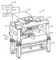
도 1 은 본 발명에 따른 리소그래피 시스템의 사시도,1 is a perspective view of a lithographic system according to the present invention,
도 2 는 도 1에 도시된 리소그래피 시스템의 간략한 정면도,2 is a simplified front view of the lithographic system shown in FIG. 1,
도 3 은 임프린트 층을 패턴화한 후에 도 1에 도시된 임프린트 층으로부터 이격된 몰드의 간략한 정면도,3 is a simplified front view of a mold spaced apart from the imprint layer shown in FIG. 1 after patterning the imprint layer;
도 4 는 제1 임프린트 층에 패턴이 전달된 후에 도 3에 도시된 기판의 최상부에 위치된 추가적인 임프린트 층의 간략한 정면도,4 is a simplified front view of an additional imprint layer located on top of the substrate shown in FIG. 3 after the pattern has been transferred to the first imprint layer;
도 5 는 본 발명에 따른 임프린트 헤드, 액추에이터 서브-어셈블리 및 템플릿의 분해도,5 is an exploded view of an imprint head, actuator sub-assembly and template according to the present invention;
도 6 은 본 발명에 따른 척 시스템의 단면도,6 is a cross-sectional view of the chuck system according to the present invention;
도 7 은 본 발명에 따른 템플릿 및 템플릿 척을 나타내는 배향 스테이지의 분해 사시도,7 is an exploded perspective view of an orientation stage showing a template and a template chuck in accordance with the present invention;
도 8 은 도 7에 도시된 배향 스테이지의 사시도,8 is a perspective view of the orientation stage shown in FIG. 7, FIG.
도 9 는 본 발명의 제1 실시예에 따른 템플릿 홀더 및 템플릿과 함께 도 7에 도시된 배향 스테이지에 포함된 패시브 컴플라이언트 장치의 분해 사시도,9 is an exploded perspective view of a passive compliant device included in the orientation stage shown in FIG. 7 together with a template holder and a template according to a first embodiment of the present invention;
도 10 은 도 9에 도시된 패시브 컴플라이언트 장치의 세부 사시도,10 is a detailed perspective view of the passive compliant device shown in FIG. 9, FIG.
도 11 은 그 안에 포함된 플렉셔 조인트를 상세하게 나타낸 도 10에 도시된 패시브 컴플라이언트의 측면도,FIG. 11 is a side view of the passive compliant shown in FIG. 10 detailing the flexure joint included therein; FIG.
도 12 는 도 10에 도시된 패시브 컴플라이언트 장치의 측면도,12 is a side view of the passive compliant device shown in FIG. 10;
도 13 은 90도 회전된 도 12에 도시된 패시브 컴플라이언트 장치의 측면도,FIG. 13 is a side view of the passive compliant device shown in FIG. 12 rotated 90 degrees;
도 14 는 180도 회전된 도 10에 도시된 패시브 컴플라이언트 장치의 측면도,14 is a side view of the passive compliant device shown in FIG. 10 rotated 180 degrees, FIG.
도 15 는 270도 회전된 도 10에 도시된 패시브 컴플라이언트 장치의 측면도,15 is a side view of the passive compliant device shown in FIG. 10 rotated 270 degrees;
도 16 은 도 6에 도시된 척 보디의 저면도,16 is a bottom view of the chuck body shown in FIG. 6, FIG.
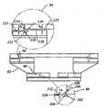
도 17 은 템플릿의 치수를 변화시키기 위하여 사용되는 도 5에 도시된 장치의 저면 사시도,FIG. 17 is a bottom perspective view of the apparatus shown in FIG. 5 used to change the dimensions of the template; FIG.
도 18 은 도 17에 도시된 장치의 위에서 아래로 본 사시도,18 is a perspective view from above of the device shown in FIG. 17,
도 19 는 본 발명에 따른 도 17 및 18에 도시된 레버 서브-어셈블리의 세부 측면도,19 is a detailed side view of the lever sub-assembly shown in FIGS. 17 and 18 in accordance with the present invention;
도 20 은 본 발명에 따라 피벗을 구비한 도 5에 도시된 액추에이터 서브-어셈블리, 플렉셔 장치의 분해 사시도,20 is an exploded perspective view of the actuator sub-assembly, flexure device shown in FIG. 5 with a pivot according to the invention, FIG.
도 21 은 도 20에 도시된 피벗의 하나의 세부 사시도,21 is a detailed perspective view of one of the pivots shown in FIG. 20;
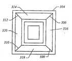
도 22 는 임프린트 층이 그 위에 위치되는 도 2, 3 및 4에 도시된 웨이퍼의 평면도,FIG. 22 is a plan view of the wafer shown in FIGS. 2, 3 and 4 with an imprint layer positioned thereon;
도 23 은 임프린트 영역 중의 하나에서 몰드의 위치를 나타내는 도 22의 상세도,FIG. 23 is a detail view of FIG. 22 showing the position of the mold in one of the imprint regions; FIG.
도 24 는 변경 실시예에 따른 도 16에 도시된 척 보디의 저면도,24 is a bottom view of the chuck body shown in FIG. 16 in accordance with a modified embodiment;
도 25 는 제2 변경 실시예에 따른 도 17에 도시된 척 보디의 단면도,25 is a cross-sectional view of the chuck body shown in FIG. 17 according to the second modified embodiment;
도 26 은 본 발명에 따른 임프린트 리소그래피 기술을 사용하여 형성되는 패턴에서 뒤틀림을 감소시키는 방법을 도시한 흐름도, 및26 is a flow chart illustrating a method of reducing distortion in a pattern formed using an imprint lithography technique in accordance with the present invention; and
도 27 은 본 발명의 변경 실시예에 따른 임프린트 리소그래피 기술을 사용하여 형성되는 패턴에서 뒤틀림을 감소시키는 방법을 도시한 흐름도.FIG. 27 is a flow chart illustrating a method of reducing distortion in a pattern formed using an imprint lithography technique in accordance with an alternative embodiment of the present invention. FIG.
도 1은 브리지(14)를 갖고 있는 한 쌍의 이격된 브리지 지지부(12)와 그 사이에 뻗어 있는 스테이지 지지부(16)를 포함하고 있는 본 발명의 한 실시예에 따른 리소그래피 시스템(10)을 도시하고 있다. 브리지(14)와 스테이지 지지부(16)는 이격되어 있다. 브리지(14)로부터 스테이지 지지부(16)를 향하여 뻗어 있는 임프린트 헤드(18)가 브리지(14)에 연결되어 있다. 임프린트 헤드(18)와 마주하여 스테이지 지지부(16)에 배치된 것은 이동 스테이지(20)이다. 이동 스테이지(20)는 스테이지 지지부(16)에 대하여 X축 및 Y축으로 이동하도록 구성되어 있지만, Z축을 따라서도 이동할 수 있다. 대표적인 이동 스테이지 장치는 본 발명의 양수인에게 양도된 "단계 및 반복 임프린트 리소그래피 시스템"의 제목으로 2000년 7월 11일 출원한 미국특허 출원번호 10/194,414에 개시되어 있다. 소스(22)는 이동 스테이 지(20)에 화학선 에너지를 충돌시키기 위하여 시스템(10)에 연결되어 있다. 시스템(10)의 작동은 시스템(10)의 여러 구성요소의 작동을 조절하는 명령을 정의하는 컴퓨터 판독가능한 코드를 포함하고 있는 메모리(33)와 데이터 통신하는 프로세서(31)의 제어하에서 이루어진다.1 shows a
도 1 및 2를 참조하면, 임프린트 헤드(18)에 연결된 것은 그 위에 몰드(28)를 갖고 있는 템플릿(26) 이다. 몰드(28)는 복수의 이격된 함몰부(27)와 돌출부(29)에 의해 형성되는 복수의 피쳐를 포함하고 있다. 이 복수의 피쳐는 이동 스테이지(20)상에 위치된 웨이퍼(30)에 전달되는 패턴의 기초를 형성하는 오리지널 패턴을 정의한다. 이러한 목적으로, 임프린트 헤드(18)는 Z축을 따라 이동하여 몰드(28)와 웨이퍼(30) 사이의 거리 "d"를 변경하기 적합하게 되어 있지만, 마찬가지로 X축 및 Y축을 따라서 이동할 수 있다. 이 방식에서, 몰드상의 피쳐는 웨이퍼의 유동가능한 영역내에 임프린트 될 수 있으며, 상세한 내용은 이하에서 설명된다. 소스(22)는 몰드(28)가 소스(22)와 웨이퍼(30) 사이에 위치되도록 배치된다. 그러므로, 몰드(28)는 소스(22)에 의해 생성되는 에너지를 실질적으로 투과시키도록 허용하는 재료로 제조된다.1 and 2, connected to the
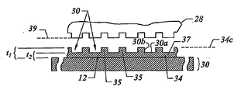
도 2를 참조하면, 유동가능한 영역은 대체로 평면의 윤곽으로 나타낸 표면의 일부에 형성된다. 유동가능한 영역은 미국특허 제5,772,905에 개시된 고온 엠보싱 공정, 또는 Chou 등에 의해 2002년 6월 네이처의 페이지 835-837 컬럼 417에 설명된 실리콘에 나노구조의 초고속 직접 임프린트 하는 타입의 레이저 보조 직접 임프린트(LADI) 공정과 같은 임의의 공지 기술을 사용하여 형성될 수 있다. 그러나, 본 실시예에서, 유동가능한 영역은 웨이퍼(30)상의 복수의 이격된 불연속적인 임프린트 재료의 액적(36)으로 구성되어 있으며, 상세한 내용은 이하에서 설명된다. 액적(36)을 침착하기 위한 대표적인 시스템은 본 발명의 양수인에게 양도된 "액상을 분배하기 위한 시스템 및 방법"의 제목으로 2002년 7월 9일 출원된 미국특허 출원번호 10/191,749에 개시되어 있다. 액적(36)은 그 안에 오리지널 패턴에 상응하는 패턴을 기록하기 위하여 선택적으로 중합 및 교차 결합 될 수 있는 임프린트 재료를 포함하고 있으며, 임프린트 층(34)에 형성된 기록 패턴을 한정한다. 임프린트 재료의 대표적인 조성물은 "몰드의 패턴과 정합 영역 사이의 부착을 감소시키는 방법"의 제목으로 2003년 6월 16일 출원된 미국특허 출원번호 10/463,396에 개시되어 있다.With reference to FIG. 2, the flowable region is formed in a portion of the surface that is generally outlined in a plane. The flowable region is a laser assisted direct imprint (LADI) type of ultrafast direct imprint of nanostructures on silicon as described in the high temperature embossing process disclosed in U.S. Patent No. 5,772,905 or by Chou et al. It can be formed using any known technique, such as) process. However, in the present embodiment, the flowable region consists of
도 2 및 3을 참조하면, 임프린트 층(34)에 기록된 패턴은 몰드(28)와의 상호작용 예를 들면 기계적인 접촉, 전기적인 접촉 등에 의해서 부분적으로 만들어진다. 본 실시예에서, 액적(36)이 몰드(28)와 기계적으로 접촉하여 임프린트 층(34)을 형성하기 위해 응고될 수 있는 표면(32)상에 임프린트 재료의 접촉 구조를 형성할 수 있도록 거리(d)는 감소된다. 한 실시예에서, 임프린트 층(34)의 하위 부분(35)이 함몰부(27)내로 진입하여 충전될 수 있도록 거리(d)는 감소된다.2 and 3, the pattern recorded on the
함몰부(27)의 충전을 촉진하기 위하여, 사용되는 임프린트 재료는 표면(32)을 임프린트 재료의 접촉 구조로 덮는 한편 함몰부(27)를 완전히 충전하는 바람직한 성질을 갖고 있다. 본 실시예에서, 돌출부(29)와 포개지는 임프린트 층(34)의 하위 부분(37)은 일반적으로 바람직한 최소 거리(d)가 달성된 이후에도 유지되며, 두께(t1)을 갖는 하위 부분(35) 및 두께(t2)를 갖는 하위 부분(37)을 남긴다. 두께 "t1" 및 "t2"는 응용에 따라 원하는 임의의 두께가 될 수 있다.In order to facilitate the filling of the
도 2 및 3을 참조하면, 바람직한 거리(d)가 달성된 후, 소스(22)는 임프린트 재료를 중합 및 교차 결합하는 화학선 에너지를 생성하고, 교차 결합된 폴리머 재료를 형성한다. 결과적으로, 임프린트 재료의 조성물은 액상에서 고상으로 변태한다. 특히, 임프린트 재료는 몰드(28)의 표면(39) 형상과 일치하는 형상을 갖는 면을 임프린트 층(34)에 제공하도록 응고되는데, 도 3에 더욱 명확하게 도시되어 있다. 응고된 임프린트 층(34)의 형성 후에, 몰드(28)와 응고된 임프린트 층(34)이 이격되도록 거리(d)는 증가된다.2 and 3, after the desired distance d is achieved, the
도 3을 참조하면, 웨이퍼(30)의 패턴을 완성하기 위하여 추가적인 공정이 사용될 수 있다. 예를 들면, 응고된 임프린트 층(34)의 패턴을 웨이퍼(30)로 전달하기 위하여 웨이퍼(30) 및 응고된 임프린트 층(34)은 에칭될 수 있으며, 도 4에 도시된 패턴 표면(294)을 제공한다. 다시 도 3을 참조하면, 에칭을 촉진하기 위하여 응고된 임프린트 층(34)이 형성되는 재료는 원하는 바에 따라 웨이퍼(30)에 대한 상대적인 에칭 속도를 한정하기 위하여 변경될 수 있다. 대안으로 또는 추가적으로, 응고된 임프린트 층(34)은 그 위에 선택적으로 침착되는 광저항 재료(도시 생략)에 대하여 상이하게 에칭되는 것으로 제공될 수 있다. 광저항 재료(도시 생략)는 공지 기술을 사용하여 응고된 임프린트 층(34)에 또 다른 패턴을 제공할 수 있다. 웨이퍼(30) 및 응고된 임프린트 층(34)을 형성하는 하부 조성물과 원하는 에 칭 속도에 따라 임의의 에칭 공정이 사용될 수 있다. 대표적인 에칭 공정에는 플라즈마 에칭, 반응성 이온 에칭, 화학적 습식 에칭 등이 포함될 수 있다. 웨이퍼(30)는 일반적인 의미로 사용되는 것이며 설명한 공정으로 패턴을 형성하기 적합한 임의의 타입의 기판을 포함할 수 있다. 예를 들면 웨이퍼(30)는 그 위에 자연적인 산화물이 있거나 또는 없는 가공하지 않은 반도체 웨이퍼(30), 예를 들어 실리콘 웨이퍼가 될 수 있다. 또한, 웨이퍼(30)는 미국 미저리주 롤라에 소재한 Brewer Science, Inc.로부터 판매되는 상품명 DUV30J-6의 재료로 형성된 프라이머 층이 그 위에 하나 이상 형성된 층을 가질 수 있다.Referring to FIG. 3, additional processes may be used to complete the pattern of the
도 1 및 2를 참조하면, 대표적인 소스(22)는 자외선 에너지를 생성할 수 있다. 열 소스, 전자기 소스 등과 같은 다른 에너지 소스가 사용될 수 있다. 임프린트 재료의 중합 반응을 일으키기 위하여 사용되는 에너지의 선택은 당업자에게 공지되어 있으며 일반적으로 원하는 특정 응용에 의존한다. 또한, 몰드(28)상의 복수의 피쳐는 몰드(28)의 단면에 방어벽 형상을 제공하는 돌출부(29)와 평행한 방향을 따라 뻗은 함몰부(27)로 도시되어 있다. 그러나, 함몰부(27) 및 돌출부(29)는 집적 회로를 생성하기 위한 피쳐를 포함하는 임의의 원하는 피쳐와 실질적으로 상응하며 나노미터와 같이 작은 것이 될 수 있다. 결과적으로, 열적으로 안정한 예를 들면 대략 실온에서(예를 들어 25℃) 약 10ppm/℃보다 작은 열팽창 계수를 가진 재료로부터 시스템(10)의 구성요소를 제조하는 것이 바람직하다. 일부 실시예에서, 구성 재료는 약 10ppm/℃보다 작거나 또는 1ppm/℃보다 작은 열팽창 계수를 가질 수 있다. 이러한 목적을 위해, 브리지 지지부(12), 브리지(14) 및/또는 스테 이지 지지부(16)는 상품명 INMAR? 또는 상품명 SUPER INVAR?로 입수가능한 철합금, 세라믹, ZERODUR? 세라믹에 한정되지는 않지만 이를 포함하는 세라믹 및 실리콘 카바이드 중의 하나 이상의 재료로 제조될 수 있다. 추가적으로 테이블(24)은 주위 환경에서의 진동으로부터 시스템(10)의 나머지 구성요소를 격리하도록 구성될 수 있다. 대표적인 테이블(24)은 미국 캘리포니아 얼바인의 뉴포트 코포레이션으로부터 입수할 수 있다.1 and 2, an
도 5 및 6을 참조하면, 그 위에 몰드(28)가 있는 템플릿(26)은 척 보디(42)를 통해 도 1에 도시된 임프린트 헤드(18)에 연결된다. 보디(42)는 플렉셔(41)에 연결된다. 플렉셔(41)는 템플릿(26)의 이동을 제어하는 배향 시스템(43)에 연결된다.5 and 6, the
도 7을 참조하면, 배향 시스템(43)은 외부 프레임(46)에 근접하여 배치된 내부 프레임(44)과 플렉셔 링(48)을 갖고 있는 것으로 도시되어 있으며, 이하에서 보다 상세하게 설명된다. 보디(42)는 플렉셔(41)를 통하여 도 8에 더욱 명확하게 도시된 배향 시스템(43)에 연결된다. 특히, 보디(42)는 보디(42)의 네개의 코너에 가장 가까운 플렉셔의 네개의 코너에 연결되는 보디(42)의 네개의 코너에 배치된 나사가공된 파스너(도시 생략)와 같은 임의의 적합한 수단을 사용하여 플렉셔(41)에 연결된다. 내부 프레임(44)의 표면(45)에 가장 가까운 플렉셔(41)의 네개의 코너(47)는 도시 생략된 나사가공된 파스너와 같은 임의의 적합한 수단을 사용하여 연결된다.Referring to FIG. 7, the
도 7 및 8을 참조하면, 내부 프레임(44)은 중앙 관통로(50)를 갖고 있으며, 외부 프레임(46)은 중앙 관통로(50)와 중첩된 중앙 개구(52)를 갖고 있다. 플렉셔 링(48)은 예를 들면 원형 또는 타원형의 환형상이고, 내부 프레임(44) 및 외부 프레임(46)에 연결되며, 중앙 관통로(50) 및 중앙 개구(52)의 외측에 놓여 있다. 특히, 플렉셔 링(48)은 나사가공된 파스너(도시 생략)와 같은 임의의 적합한 수단을 사용하여 영역(54, 56, 58)에서 내부 프레임(44), 영역(60, 62, 64)에서 외부 프레임(46)에 연결된다. 영역(60)은 영역(54)과 영역(56) 사이에서 같은 거리에 배치되고, 영역(64)은 영역(54)과 영역(58) 사이에서 같은 거리에 배치된다. 이 방식에서, 플렉셔 링(48)은 플렉셔(41), 보디(42) 및 템플릿(26)을 둘러싸고 내부 프레임(44)을 외부 프레임(46)에 견고하게 부착한다.7 and 8, the
배향 시스템(43)과 플렉셔(41)의 구성요소는 예를 들면 알루미늄, 스테인리스강 등과 같은 임의의 적합한 재료로 형성될 수 있다. 부가적으로, 플렉셔(41)는 임의의 적합한 수단을 사용하여 배향 시스템(43)에 연결될 수 있다. 본 실시예에서, 플렉셔(41)는 보디(42)의 네개의 코너에 배치된 나사가공된 파스너(도시 생략)을 사용하여 표면(45)에 연결된다.The components of the
배향 시스템(43)은 템플릿(26)의 이동을 제어하고 기준면(도시 생략)에 대하여 원하는 공간 관계에 위치시키도록 구성되어 있다. 이러한 목적으로 위해, 복수의 액추에이터(66, 68, 70)는 배향 시스템(43) 주위에 간격을 두도록 내부 프레임(44)과 외부 프레임(46) 사이에 연결된다. 각각의 액추에이터(66, 68, 70)는 제1 단부(72)와 제2 단부(74)를 가지고 있다. 제1 단부(72)는 외부 프레임(46)과 마주하고 제2 단부(74)는 내부 프레임(44)과 마주한다. 액추에이터(66, 68, 70)는 세 개의 축선(Z1, Z2, Z3)을 따라 내부 프레임(44)의 병진 이동을 용이하게 함으로써 외부 프레임(46)에 대하여 내부 프레임(44)을 틸팅시킨다. 배향 시스템(43)은 축선(Z1, Z2, Z3)에 대하여 약 ±1.2mm 범위의 이동 범위를 제공할 수 있다. 이 방식에서, 액추에이터(66, 68, 70)는 내부 프레임(44)이 하나 이상의 복수의 축선(T1, T2, T3)에 대하여 플렉셔(41), 템플릿(26) 및 보디(42)를 각도 이동시키도록 한다. 특히, 축선(Z2, Z3)을 따라 내부 프레임(44)과 외부 프레임(46) 사이의 거리를 감소시키고 축선(Z1)을 따라 그 사이의 거리를 증가시킴으로써 틸팅 축선(T2)에 대한 각도 이동은 제1 방향에서 일어난다. 축선(Z2, Z3)을 따라 내부 프레임(44)과 외부 프레임(46) 사이의 거리를 증가시키고 축선(Z1)을 따라 그 사이의 거리를 감소시키면 틸팅 축선(T2)에 대한 각도 이동은 제1 방향과 반대인 제2 방향에서 일어난다. 유사한 방식으로, 틸팅 축선(T1)에 대한 각도 이동은 축선(Z1, Z2)을 따라 같은 방향 및 크기로 내부 프레임(44)을 이동시키는 한편 축선(Z1, Z2)을 따라 반대 방향 및 두배의 크기로 축선(Z3)을 따라 내부 프레임(44)을 이동시킴으로써 내부 프레임(44)과 외부 프레임(46) 사이의 거리를 변화시키는 것에 의해서 일어날 수 있다. 마찬가지로, 틸팅 축선(T3)에 대한 각도 이동은 축선(Z1, Z3)을 따라 같은 방향 및 크기로 내부 프레임(44)을 이동시키는 한편 축선(Z1, Z3)을 따라 반대 방향 및 두배 의 크기로 축선(Z2)을 따라 내부 프레임(44)을 이동시킴으로써 내부 프레임(44)과 외부 프레임(46) 사이의 거리를 변화시키는 것에 의해서 일어날 수 있다. 액추에이터(66, 68, 70)는 ±200 N의 최대 작동력을 가질 수 있다. 배향 시스템(43)은 축선(T1, T2, T3)에 대하여 약 ±0.15°의 이동 범위를 제공할 수 있다.The
액추에이터(66, 68, 70)는 기계적인 부품을 최소화하도록 선택되며, 따라서 미립자에 의한 마찰뿐만 아니라 불균일한 역학적인 컴플라이언스를 최소화한다. 액추에이터(66, 68, 70)의 예는 보이스 코일 액추에이터, 피에조 액추에이터 및 리니어 액추에이터를 포함한다. 액추에이터(66, 68, 70)에 대한 대표적인 실시예는 미국 캘리포니아 실마의 BEI Technologies로부터 입수가능한 상품명 LA24-20-000A이며, 예를 들면 나사가공된 파스너와 같은 적합한 수단을 사용하여 내부 프레임(44)에 연결된다. 추가적으로, 액추에이터(66, 68, 70)는 대칭으로 중앙 관통로(50) 및 중앙 개구(52) 외부에 배치되도록 내부 프레임(44)과 외부 프레임(46) 사이에 연결된다. 이러한 구조로 외부 프레임(46)과 플렉셔(41) 사이에 방해받지 않는 관통로가 구성된다. 추가적으로, 대칭적인 배열은 동적 진동 및 불균일한 열적 흐름을 최소하고, 이에 의해 내부 프레임(44)의 정교한 이동 보정을 제공한다.
내부 프레임(44), 외부 프레임(46), 플렉셔 링(48) 및 액추에이터(66, 68, 70)의 조합은 플렉셔(41)의 각도 이동을 제공하고, 따라서 틸팅 축선(T1, T2, T3)에 대한 보디(42)와 템플릿(26)의 각도 이동을 제공한다. 그러나, 병진 이동은 축선(Z1, Z2, Z3)과 비록 직교하지는 않더라도 가로질러 뻗은 평면에 놓인 축선을 따라 템플릿(26)에 부여되는 것이 바람직하다. 이것은 틸팅 축선(T1, T2, T3)으로부터 떨어져 있고 템플릿, 템플릿 척 및 컴플라이언트 장치가 조립될 때 템플릿의 표면에 존재하는 하나 이상의 복수의 컴플라이언스 축선(C1, C2)에 대하여 템플릿(26)에 각도 이동을 부여하는 기능을 플렉셔(41)에 제공함으로써 달성된다.The combination of the
도 9 및 10을 참조하면, 플렉셔(41)는 지지 보디(76) 및 복수의 플렉셔 암(80, 82, 84, 86)과 마주하는 지지 보디(76)에 연결되는 플로팅 보디(78)를 포함한다. 보디(42)는 전술한 바와 같이 플로팅 보디(78)에 창착되도록 의도된 것이며 템플릿(26)은 이하에서 상세하게 설명되는 도 6에 도시된 통상적인 방법을 사용하는 척 시스템(40)에 의해 유지된다.9 and 10, the
다시 도 9 및 10을 참조하면, 각각의 플렉셔 암(80, 82, 84, 86)은 제1 및 제2 세트의 플렉셔 조인트(88, 90, 92, 94)를 포함한다. 제1 및 제2 세트의 플렉셔 조인트(88, 90, 92, 94)는 설명의 편의를 위해 플렉셔 암(88)에 대하여 설명되지만, 이러한 설명은 플렉셔 암(80, 84, 86)과 관련된 플렉셔 조인트의 세트에 동일하게 적용된다. 비록 필수적이진 않지만, 플렉셔(41)는 솔리드 보디로 형성된다. 그 결과, 지지 보디(76), 플로팅 보디(78) 및 플렉셔 암(80, 82, 84, 86)은 일체로 형성되며 마주하는 제1 및 제2 세트의 플렉셔 조인트(88, 90, 92, 94)와 함께 회전가능하게 연결된다. 지지 보디(76)는 중앙에 배치된 관통로(96)를 포함하고 있다. 플로팅 보디(78)는 관통로(96)와 포개지는 중앙에 배치된 구멍(98)을 포함하고 있다. 각각의 플렉셔 암(80, 82, 84, 86)은 마주보는 단부(99, 100)를 포 함하고 있다. 각각의 플렉셔 암(80, 82, 84, 86)의 단부(99)는 플렉셔 조인트(92, 94)를 통하여 지지 보디(76)에 연결된다. 단부(99)는 관통로(96)의 외부에 놓여 있다. 각각의 플렉셔 암(80, 82, 84, 86)의 단부(100)는 플렉셔 조인트(88, 90)를 통하여 플로팅 보디(78)에 연결된다. 단부(100)는 구멍(98)의 외부에 놓여 있다.Referring again to FIGS. 9 and 10, each
도 9, 10 및 11을 참조하면, 각각의 조인트(88, 90, 92, 94)는 단부(99, 100)에 가까운, 즉 지지 보디(76) 또는 플로팅 보디(78)와 플렉셔 암(80, 82, 84, 86)중의 하나의 계면에서 플렉셔(41)의 재료를 감소시킴으로써 형성된다. 이러한 목적을 위해, 플렉셔 조인트(88, 90, 92, 94)는 플렉셔(41)의 기계 가공, 레이저 절단 또는 다른 적합한 공정에 의해 형성된다. 특히, 조인트(90, 92)는 두개의 마주 보는 표면(104, 106)과 두개의 틈(108, 110)을 갖는 플렉셔 부재(102)로부터 형성된다. 틈(108)은 틈(110)으로부터 떨어져 마주하여 위치되고, 틈(110)은 틈(108)으로부터 떨어져서 마주하고 있다. 표면(104)에서 떨어져서 틈(100)으로부터 뻗은 것은 갭(112)이고, 플렉셔 암(82)의 둘레의 개구에서 끝난다. 또한 조인트(94)는 두개의 마주보는 표면(116, 118)과 두개의 틈(120, 122)를 갖는 플렉셔 부재(114)로부터 형성된다. 틈(122)은 표면(118)과 반대쪽에 배치된다. 표면(116)에서 떨어져서 틈(122)으로부터 뻗은 것은 갭(123)이고, 틈(120)으로부터 뻗은 것은 갭(125)이다. 갭(112, 123, 125)의 간격(S1, S2, S3)은 지지 보디(76)와 플로팅 보디(78)중의 하나 사이에서 상대 이동이 일어날 수 있는 이동 범위를 각각 한정한다.9, 10 and 11, each joint 88, 90, 92, 94 is close to the
도 9 및 11을 참조하면, 플렉셔 암(82, 84)의 조인트(88)와 관련한 플렉셔 부재(114)는 축선(124)에 대한 회전을 용이하게 하고, 플렉셔 암(82, 84)의 조인트(92)와 관련한 플렉셔 부재(102)는 축선(126)에 대한 회전을 용이하게 한다. 플렉셔 암(80, 86)의 조인트(88)와 관련한 플렉셔 부재(114)는 축선(128)에 대한 회전을 촉진하고, 플렉셔 암(80, 86)의 조인트(92)와 관련한 플렉셔 부재(102)는 축선(130)에 대한 회전을 용이하게 한다. 플렉셔 암(80, 82)의 조인트(90)와 관련한 플렉셔 부재(102)는 축선(132)에 대한 회전을 용이하게 하고, 플렉셔 암(80, 82)의 조인트(94)와 관련한 플렉셔 부재(114)는 축선(134)에 대한 회전을 용이하게 한다. 플렉셔 암(84, 86)의 조인트(90)와 관련한 플렉셔 부재(102)는 축선(136)에 대한 회전을 용이하게 하고, 플렉셔 암(84, 86)의 조인트(94)와 관련한 플렉셔 부재(114)는 축선(138)에 대한 회전을 용이하게 한다.9 and 11, the flexure member 114 relative to the joint 88 of the
그 결과, 각각의 플렉셔 암(80, 82, 84, 86)은 회전 축선의 그룹이 겹쳐지는 플렉셔(41)의 영역에 위치된다. 예를 들면, 플렉셔 암(80)의 단부(99)는 축선(130)과 축선(134)이 겹쳐지는 곳에 위치되고, 단부(100)는 축선(128)과 축선(132)이 겹쳐지는 곳에 위치된다. 플렉셔 암(82)의 단부(99)는 축선(126)과 축선(134)이 겹쳐지는 곳에 위치되고, 단부(100)는 축선(124)과 축선(132)이 겹쳐지는 곳에 위치된다. 플렉셔 암(84)의 단부(99)는 축선(138)과 축선(126)이 겹쳐지는 곳에 위치되고, 단부(100)는 축선(124)과 축선(136)이 겹쳐지는 곳에 위치된다. 마찬가지로, 플렉셔 암(86)의 단부(99)는 축선(130)과 축선(138)이 겹쳐지는 곳에 위치되고, 단부(100)는 축선(136)과 축선(128)이 겹쳐지는 곳에 위치된다.As a result, each
이러한 구성의 결과, 각각의 플렉셔 암(80, 82, 84, 86)은 제1 그룹이 나머지 그룹에 대하여 가로질러 뻗은 상태에서 두 그룹의 겹쳐진 두 그룹의 축선 주위로 지지 보디(76)와 플로팅 보디(78)에 대한 상대 회전 이동을 제공하도록 연결된다. 이것은 각각의 플렉셔 암(80, 82, 84, 86)이 직교하는 두 그룹의 축선 주위로 이동하도록 하는 한편 플렉셔 암의 풋프린트를 최소화한다. 플렉셔(41)는 상술한 축선 위에서 약 ±0.04°의 틸팅 이동 범위, 약 ±0.02°의 액티브 틸팅 이동 범위, 약 ±0.0005°의 액티브 세타 틸팅 이동 범위를 제공할 수 있다. 게다가, 각각의 플렉셔 암(80, 82, 84, 86)이 감소된 풋프린트를 갖는다는 것은 관통로(96)와 구멍(98) 사이에 플렉셔 암(80, 82, 84, 86)에 의해 방해되지 않는 공간을 남겨두도록 허용한다. 이것은 임프린트 리소그래피 시스템으로 사용하기 적합한 플렉셔(41)를 만든다.As a result of this configuration, each
도 10, 12 및 13을 참조하면, 지지 보디(76)와 플로팅 보디(78)에 대한 플렉셔 암(80, 82, 84, 86)의 구성은 플렉셔(41)에서 하중의 평행한 전달을 용이하게 한다. 예를 들면, 지지 보디(76)에 하중이 부여되면 각각의 플렉셔 암(80, 82, 84, 86)은 실질적으로 같은 양의 힘(F1)을 플로팅 보디(78)에 분배한다. 특히, 이것은 힘(F1) 또는 힘(F2)으로 부하가 가해질 때 플렉셔(41)로 원하는 구조적인 강성을 얻는 것을 촉진한다. 그 때문에, 조인트(88, 90, 92, 94)는 모든 방향에서 플렉셔와 지지 보디(76) 또는 플로팅 보디(78) 사이에 회전 이동을 제외한 이동을 최소화하는 회전 조인트이다. 특히, 조인트(88, 90, 92, 94)는 플렉셔 암(80, 82, 84, 86), 지지 보디(76), 플로팅 보디(78) 사이의 병진 이동을 최소화하는 한편, 축선(124, 136, 128, 130, 132, 134, 136, 138)에 대한 회전 이동을 용이하게 한다.10, 12, and 13, the configuration of
도 10, 11, 12 및 13을 참조하면, 축선(124, 126, 128, 130)의 상대 위치는 플로팅 보디(78)로부터 떨어져 있고 구멍(98)과 축선(124, 126, 128, 130)에 대하여 중앙의 위치에서 제1 원격 중앙 컴플라이언스(remote center of compliance(RCC))를 갖는 플로팅 보디(78)를 제공한다. 마찬가지로, 축선(122, 124, 136, 138)의 상대 위치는 위치(140)에 실질적으로 가깝고 바람직하게는 위치(140)에 배치된 제2 원격 중앙 컴플라이언스를 갖는 플로팅 보디(78)를 제공하는데, 이것은 축선(132, 134, 136, 138)에 대하여 실질적으로 중앙에서 위치(140)로부터 같은 거리에 위치된다. 축선(124, 126, 128, 130)의 그룹의 각각의 축선은 그 그룹의 나머지 축선(124, 126, 128, 130)과 평행하며 각각의 축선(124, 126, 128, 130)과 직교하여 뻗어 있다. 축선(130)은 제1 방향을 따라 거리(d1) 및 제2 직교 방향을 따라 거리(d2)만큼 축선(128)으로부터 떨어져 있다. 축선(124)은 제2 방향을 따라 거리(d3) 및 제1 방향을 따라 거리(d4)만큼 축선(126)으로부터 떨어져 있다. 축선(132)은 제1 방향 및 제2 방향과 모두 직교하는 제3 방향을 따라 거리(d5) 및 제1 방향을 따라 거리(d6)만큼 축선(134)으로부터 떨어져 있다. 축선(136)은 제1 방향을 따라 거리(d7) 및 제3 방향을 따라 거리(d8)만큼 축선(138)으로부터 떨어져 있다. 거리(d1, d4, d6, d7)는 실질적으로 같다. 거리(d2, d3, d5, d8)는 실질적으로 같다.10, 11, 12, and 13, the relative positions of the
도 12, 13, 14 및 15를 참조하면, 원격 중앙 컴플라이언스가 적절하게 설정한 거리(d1 - d8)에 의해 그 교점상에 위치하도록 두 세트의 가로질러 뻗은 축선은 실질적으로 아주 근접하여 위치될 수 있다. 네개의 축선을 포함하는 제1 세트는 도면 부호 144, 146, 148, 150으로 도시되어 있다. 플렉셔 암(80)의 조인트(88, 92)는 축선(144)을 따라 놓여 있고, 플렉셔 암(82)의 조인트(88, 92)는 축선(146)을 따라 놓여 있다. 플렉셔 암(84)의 조인트(88, 92)는 축선(148)을 따라 놓여 있고, 플렉셔 암(86)의 조인트(88, 92)는 축선(150)을 따라 놓여 있다. 네개의 축선을 포함하는 제2 세트는 도면 부호 152, 154, 156, 158로 도시되어 있다. 플렉셔 암(82)의 조인트(90, 94)는 축선(152)을 따라 놓여 있고, 플렉셔 암(84)의 조인트(90, 94)는 축선(154)을 따라 놓여 있다. 플렉셔 암(86)의 조인트(90, 94)는 축선(156)을 따라 놓여 있고, 플렉셔 암(80)의 조인트(90, 94)는 축선(158)을 따라 놓여 있다. 이러한 구성에서 원격 중앙 컴플라이언스에 대하여 축선(144, 146, 148, 150, 152, 154, 156, 158) 세트의 임의의 하나에 대한 플로팅 보디(78)의 이동은 나머지 축선(144, 146, 148, 150, 152, 154, 156, 158)에 대한 이동으로부터 분리된다. 이것은 원격 중앙 컴플라이언스에 대한 플로팅 보디(78)의 짐벌식 이동을 제공한다. 비록 방지하지는 않더라도 축선(144, 146, 148, 150, 152, 154, 156, 158)에 대한 플로팅 보디(78)의 병진 이동을 저지하는 구조적인 강성을 갖는다.Referring to Figures 12, 13, 14 and 15, the two sets of transverse axes are positioned substantially in close proximity so that the remote central compliance is located at their intersection by a properly set distance d1 -d8 . Can be. The first set comprising four axes is shown at 144, 146, 148, 150.
도 6 및 16을 참조하면, 척 보디(42)는 진공 기술을 사용하여 그 위에 몰드(28)가 부착되는 템플릿(26)을 유지하기 적합하게 되어 있다. 이러한 목적을 위해, 척 보디(42)는 마주보는 제1 측면(160) 및 제2 측면(162)을 포함한다. 측면, 또는 에지, 표면(164)은 제1 측면(160)과 제2 측면(162) 사이에 뻗어 있다. 제1 측면(160)은 제1 함몰부(166), 제1 함몰부(166)로부터 이격된 제2 함몰부(168)를 포함하고 있으며, 이격된 제1 지지 영역(170)과 제2 지지 영역(172)을 한정한다. 제1 지지 영역(170)은 제2 지지 영역(172), 제1 함몰부(166) 및 제2 함몰부(168)를 둘러싼다. 제2 지지 영역(172)은 제2 함몰부(168)를 둘러싼다. 제2 함몰부(168)와 포개지는 척 보디(42)의 부분(174)은 전술한 화학선 에너지의 파장과 같은, 소정의 파장을 갖는 에너지를 투과시킨다. 이러한 목적을 위해, 부분(174)은 유리와 같은 투명한 재료의 얇은 층으로 만들어진다. 그러나, 부분(74)을 만드는 재료는 도 2에 도시된 소스(22)에 의해 생성되는 에너지의 파장에 의존하여 선택될 수 있다.6 and 16, the
다시 도 6 및 16을 참조하면, 부분(174)은 제2 측면(162)을 따라 뻗어 제2 함몰부(168) 근처에서 끝나며 몰드(28)가 포개지도록 몰드(28)의 면적과 적어도 같은 크기의 면적을 한정한다. 척 보디(42)에 형성된 것은 도면 부호 176 및 178로 도시된 하나 이상의 관통로이다. 관통로 중의 하나인 관통로(176)는 제1 함몰부(166)를 측면(164)과 유체 연통하게 한다. 나머지 관통로(178)는 제2 함몰부(168)를 측면(164)과 유체 연통하게 한다.Referring again to FIGS. 6 and 16, the
관통로(176)는 마찬가지로 제2 측면(162)과 제1 함몰부(166) 사이에 뻗어 있 을 수 있다. 유사하게, 관통로(178)는 제2 측면(162)와 제2 함몰부(168) 사이에 뻗어 있을 수 있다. 관통로(176, 178)는 함몰부(166, 168)를 각각 펌프 시스템(180)과 같은 압력 제어 시스템과 유체 연통하는 것을 용이하게 하는 것이 바람직하다.The through
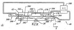
펌프 시스템(180)은 함몰부(166, 168) 근처의 압력을 서로 독립적으로 제어하기 위하여 하나 이상의 펌프를 포함할 수 있다. 특히, 척 보디(42)에 장착될 때, 템플릿(26)은 제1 지지 영역(170)과 제2 지지 영역(172)에 대하여 위치되고, 제1 함몰부(166) 및 제2 함몰부(168)를 덮는다. 포개진 템플릿(26)의 부분(182)과 제1 함몰부(166)가 제1 챔버(184)를 한정한다. 포개진 템플릿(26)의 부분(186)과 제2 함몰부(168)가 제2 챔버(188)를 한정한다. 펌프 시스템(180)은 제1 챔버(184) 및 제2 챔버(188)의 압력을 제어하도록 작동한다. 특히, 척 보디(42)와 템플릿(26)의 위치를 유지하고 중력(g)하에서 비록 회피하지는 못하더라도 척 보디(42)로부터 템플릿(26)의 분리를 감소시키기 위하여 제1 챔버(184)에 압력이 설정된다. 템플릿(26)의 형상을 조절함으로써 특히 임프린트 하는 동안에 발생하는 템플릿(26)의 비틀림을 감소시키기 위하여 제2 챔버(188)의 압력은 제1 챔버(184)의 압력과 상이할 수 있다. 예를 들면, 펌프 시스템(180)은 도 2에 도시된 임프린트 층(34)이 몰드(28)와 접촉한 결과로서 발생하는 임의의 상향의 힘(R)을 보상하기 위하여 챔버(188)에 정압을 가할 수 있다. 이 방식에서, 비록 회피할 수는 없더라도 힘(R)의 작용하에서 템플릿(26) 및 몰드(28)의 구부러짐이 감소되도록 측면(160)의 다른 영역들 사이에 압력차가 생성된다. 템플릿(26)에 연결된 것은 X 방향 및 Y 방향에서 템플릿의 치수를 변화시키기 위한 수단이며, Y 방향은 도 6의 평면에 존재한다. 치수를 변화시키기 위한 수단은 도 5의 분해도에 도시된 척 보디(42)에 연결되는 액추에이터 서브-어셈블리(190)로서 개략적으로 도시되어 있다. 펌프 시스템(180) 및 액추에이터 서브-어셈블리(190)는 도 1에 도시된 프로세서(31)의 제어하에서 작동된다.The
도 17 내지 19를 참조하면, 본 실시예에서 액추에이터 서브-어셈블리(190)는 비록 완전히 회피할 수는 없더라도 평면 외부 굽힘력이 실질적으로 최소화되도록 템플릿(26)이 순수하게 압축력을 받도록 구성된다. 템플릿(26)의 굽힘을 야기하는 힘은 패턴 뒤틀림을 초래하여 문제가 된다. 이러한 목적을 위하여, 액추에이터 서브-어셈블리(190)는 템플릿(26)의 중간 축선을 따라 압축력이 가해지도록 하는 중앙 구멍(194)을 갖는 프레임(192)에 장착된 복수의 레버 서브-어셈블리를 포함하고 있다. 각각의 레버 서브-어셈블리는 레버 암(200), 구동 시스템(202) 및 링크 시스템(204)에 연결된 보디(198)를 포함하고 있다. 레버 암(200)은 링크 시스템(204)을 통하여 보디(198)에 연결된다. 일반적으로 레버 암(200), 보디(198) 및 링크 시스템(204)은 예를 들면 알루미늄, 스테인리스강 등의 재료로 일체로 형성된다. 구동 시스템(202)의 피스톤(206)은 플렉셔 조인트(212)를 통하여 레버 암(200)의 말단 영역(208)에 연결되며 말단 영역(208)에 대하여 밀거나 당겨질 수 있다. 레버 암(200)의 제2 말단 영역(210)은 힘을 분배하기 위하여 링크 시스템(204)에 연결된다.Referring to Figures 17-19, the
각각의 레버 서브-어셈블리(196)는 프레임(192)의 제1 측면(214)에 링크 시 스템(204)이 위치되도록 프레임(192)에 장착된다. 서브-어셈블리(190)의 모든 구성요소가 금속은 아니더라도 대부분 금속인 프레임(192)은 알루미늄, 스테인리스강 등으로 형성된다. 구동 시스템(202)은 그 사이에 뻗어 있는 레버 암(200)과 함께 제1 측면(214)과 마주하여 위치된 프레임(192)의 제2 측면(215)에 위치된다. 비록 구동 시스템(202)은 당해 기술분야에 공지된 공압식, 압전식, 자기변형식, 보이스 코일식과 같은 임의의 힘 또는 변위 액추에이터가 될 수 있지만, 본 실시예에서 구동 시스템은 제품 번호 11-CUJB10-4D로서 미국 인디애나, 인디애너폴리스에 소재한 SMC Corporation of America로부터 입수가능한 액추에이터이다.Each
레버 서브-어셈블리(196)의 각각의 보디(198)는 레버 암(200)으로부터 떨어져 있는 링크 시스템(204)으로부터 구멍(194)을 향하여 뻗어 포개져서 끝난다. 비록 필수적인 것은 아니지만, 관련된 복수의 보디(198)가 구멍(194)에 대하여 대칭으로 배치되도록 프레임(192)에 연결된 복수의 레버 서브-어셈블리(196)를 가지고 있는 것이 바람직하다. 또한, 전술한 힘을 공통 프레임 즉, 프레임(192)에 분배하도록 프레임(192)에 연결된 복수의 레버 서브-어셈블리(196)를 가지고 있는 것이 바람직하다. 대안으로, 서브-어셈블리는 다른 프레임에 연결될 수 있지만 마주보는 서브-어셈블리가 공통 프레임에 연결되는 것이 바람직하다. 비록 구멍(194)은 원하는 임의의 형상을 가질 수 있지만, 일반적으로 구멍(194)은 템플릿(26)의 형상과 상보적인 형상을 갖는다. 이러한 목적을 위해, 도시된 바와 같이 구멍(194)은 정사각형이다. 또한, 복수의 보디(198)의 각각은 복수의 보디(198)의 나머지 보디(198)중의 하나와 마주하여 배치되는 것이 바람직하다. 이러한 목적을 위해, 구멍 (194)의 양쪽에 같은 수의 보디(198)가 존재한다. 비록 네개의 레버 서브-어셈블리(196)가 도시되어 있고, 구멍(194)의 한 측면에 네개의 보디(198)를 제공하지만, 임의의 수가 존재할 수 있다. 특히, 더욱 정확한 템플릿(26)의 뒤틀림 제어를 제공하기 위하여 더 많은 수의 레버 서브-어셈블리(196)가 사용될 수 있도록 각각의 레버 서브-어셈블리(196)는 더 작게 만들어질 수 있다. 이 방식에서, 면적은 템플릿(26)이 중앙에 위치되게 하는 복수의 보디(198) 사이에 한정된다. 이러한 설계가 갖는 장점은 도 3에 도시된 몰드 표면(29)이 위치되는 평면으로부터 떨어져 위치하도록 전체 액추에이터 서브-어셈블리(190)가 몰드(28)의 한 측면에 위치된다는 것이다. 이것은 임프린트 하는 동안 도 5에 도시된 액추에이터 서브-어셈블리(190)의 구성요소와 도 3에 도시된 웨이퍼(30) 사이의 접촉을 방지하는데 유리하다.Each
다시 도 17 내지 19를 참조하면, 작동하는 동안 액추에이터 서브-어셈블리(190)는 템플릿(26)을 수용하는 적절한 크기를 갖는 구멍(194)을 제공하기 위하여 말단 영역(208)에 힘을 가한다. 예를 들면, 중립 상태 즉 액추에이터 서브-어셈블리(190)에 의해 힘이 가해지지 않는 상태에서, 구멍(194)은 템플릿(26)의 치수보다 작은 치수를 가질 수 있다. 그 결과, 액추에이터 서브-어셈블리(190)는 말단 영역(208)에 대하여 잡아당기도록 작동하고 템플릿(26)의 로딩을 위해 구멍(194)의 크기를 증가시키도록 마주하는 보디(198)로부터 멀어지게 보디(198)의 후퇴를 야기한다. 템플릿(26)은 구멍(194)내에 위치되고 도 6에 도시된 척 시스템(40)을 통해서 제위치에 유지된다. 다시 도 5, 17, 18 및 19를 참조하면, 보디(198)는 구동 시스 템(202)에 의해 힘을 발생시키는 일없이 템플릿(26)에 대하여 프레스되도록 허용된다. 대안으로, 구멍(194)의 크기는 템플릿(26)의 치수보다 클 수 있으며, 템플릿(26)과 보디(198) 사이의 접촉을 달성하기 위하여 구동 시스템(202)에 의해 발생하는 힘을 필요로 한다.Referring again to FIGS. 17-19, during operation the
보디(198)는 템플릿(26)의 측면(218)과 접촉하도록 보디(198)에 접촉 표면(220)이 포함되도록 배열된다. 특히, 접촉 표면(220)은 측면(218)과 평행하게 뻗어 접촉을 이루도록 구성된다. 이러한 목적을 위해, 구동 시스템(202)이 레버 암(200)의 각도 이동을 분배하도록 도 6에 도시된 펌프 시스템(180)에 구동 시스템(202)이 연결된다. 피스톤(206)은 플렉셔 조인트(212)를 통하여 레버 암(200)의 한 단부에 힘(FIN)을 분배한다. 이것은 보디(198)가 템플릿(26)을 향하여 병진 이동을 수행하도록 레버 암(200)을 회전 이동시키고, 이에 의해 복수의 보디(198)에 의해 한정되는 면적을 감소시킨다. 이 방식에서, 템플릿(26)의 측면(218)에 힘(FOUT)이 분배된다. 템플릿(26)의 측면(218)의 다른 부분을 따라 하나 이상의 보디(198)로부터 힘(FOUT)을 분배함으로써, 템플릿(26)의 치수 변화가 달성될 수 있다. 템플릿(26)의 치수 변화가 몰드(28)에 부여되는데, 이것은 이하에 상세하게 설명되는 확대 에러를 보상하기 위하여 사용될 수 있다.
템플릿(26)의 치수를 변화시킬 때 주요한 고려 사항은 비록 회피할 수는 없더라도 몰드(28) 패턴의 뒤틀림을 초래할 수 있는 템플릿(26)에 대한 국부적인 힘 집중 및 템플릿(26)의 굽힘을 최소화하는 것이다. 이러한 목적을 위해, 링크 장치 (204)는 보디(198) 및 레버 암(200)의 진행 방향을 제어하도록 설계된다. 추가적으로 공통 프레임(192)에 서브-어셈블리(196)의 구조적인 연결은 척 보디(42) 및 템플릿(26)과 같은 다른 구성요소와 대항할 때 프레임(192)에서 큰 힘이 반작용하는 것을 보장한다.The main considerations in changing the dimensions of the
링크 장치(204)는 링크 부재(224)와 복수의 플렉셔 조인트(226, 228, 230, 232, 234, 236)를 포함한다. 각각의 플렉셔 조인트(226, 228, 230, 232, 234, 236)는 실질적으로 감소된 재료를 갖고 있는 링크 부재(224)의 영역이다. 플렉셔 조인트(226)는 말단 영역(208)에서 구동 시스템(202)의 피스톤(206)에 의해 레버 암(200)에 부여된 힘(FIN)에 반응하여 레버 암(200)이 그 주위로 회전/각도 이동을 수행하는 피벗 축선(238)을 한정한다. 피벗 축선(238)에 대한 레버 암(200)의 회전/각도 이동은 비록 직교하지는 않더라도 피벗 축선(238)을 가로지르는 방향으로 보디(198)를 이동시킨다. 편향이 최소화되도록 방향(240)이 정확하게 제어되게 하는 것이 매우 바람직하다. 이것은 복수의 보디(198)에 의한 힘(FOUT)을 받게 될 때 비록 회피하지 못하더라도 템플릿(26)의 평면 외부 굽힘을 감소시킨다. 힘(FOUT)은 레버 암(200)의 말단 영역(210)을 따라 링크 시스템(204)으로 향하게 된다.The
플렉셔 조인트(226)와 추가적으로 플렉셔 조인트(228, 230, 232)는 방향(240)으로부터 보디(198)의 편향이 최소화되는 것을 보장하는 한편 레버 암(200)과 보디(198) 사이의 회전/각도 이동을 용이하게 한다. 특히, 각각의 플렉셔 조인트(228, 230, 232)는 레버 암(200)과 보디(198) 사이의 회전/각도 이동이 그 주위에서 일어날 수 있는 회전 축선(242, 244, 26)을 개별적으로 한정한다. 축선(238, 242, 244, 246)은 평행하게 뻗어 있으며, 축선(238, 242)은 실질적으로 서로 포개지고 축선(244, 246)은 실질적으로 서로 포개진다. 축선(238, 244)은 공통 평면에 위치하고 축선(242, 246)은 공통 평면에 위치한다.The
추가적으로 말단 영역(208, 210) 사이에 축선(238)을 적절하게 위치 결정함으로써, 레버 암(200)과 링크 장치(204)는 확대기로서 기능할 수 있다. 특히, 측면(218)과 접촉 표면(220) 사이에 접촉이 존재할 때, 링크 시스템(204)에 가해지는 힘(FOUT)은 말단 영역(208, 210) 사이에 축선(238)의 위치 및 힘(FIN)의 함수이다. 힘(FOUT)의 크기는 다음과 같이 정의될 수 있다.In addition, by properly positioning the
Fout = FIN (l1/l2)Fout = FIN (l1 / l2 )
여기에서, l1은 말단 영역(208)으로부터 축선(212)의 거리이며, l2는 말단 영역(210)으로부터 축선(238)의 거리이다.Here, l1 is the distance of the
도 19 및 20을 참조하면, 템플릿(26)에 대한 순수한 압축을 유지하는 것을 촉진하도록 링크 시스템(204)은 조인트(234, 236)를 포함하고 있다. 조인트(234, 236)는 두개의 가로질러 뻗은 축선(248, 250)을 따라 레버 부재(224)에 대한 회전/각도 이동을 용이하게 한다. 축선(248, 250)에 대한 회전 자유도를 갖는 보디(198)를 제공함으로써, 보디(198)는 접촉 표면(220)에 대한 측면(218)의 기울어짐을 보상하도록 위치를 변경할 수 있다. 이 방식에서, 접촉 표면(220)은 비록 방지하지는 못하더라도, 특히 접촉 표면(220)의 코너가 측면(218)과 접촉하는 것을 초 래하는 국부적인 응력을 감소시키기 위하여 측면(218)과의 접촉을 유지한다. 접촉 표면(220)과 템플릿(26) 사이의 국부적인 응력을 더욱 감소시키기 위하여, 측면(218)과 접촉 표면(220)의 부정합을 초래하는 측면(218)의 국부적인 응력이 최소화되도록 접촉 표면(220)은 가요성 재료로 형성될 수 있다. 접촉 표면을 형성하는 예시적인 재료는 TEFLON?, 플루오르실리콘, 우레탄 및 Delrin/AF 를 포함한다. 또한 표면(218)의 표면 이형에 대한 컴플라이언스는 복수의 보디(198) 중의 하나의 보디(198)와 접촉 표면(220)에 대한 독립적인 제어를 허용함으로써 달성될 수 있다.19 and 20, the
액추에이터 서브-어셈블리(190)는 2차원에서 템플릿(26)의 치수를 변화시키는 것을 용이하게 한다. 이것은 특히 푸아송 효과를 극복하는데 유용하다. 푸아송 효과는 템플릿(26)의 직각 방향에서 변형과 선형 관계를 나타낸다. 구체적으로, 푸아송 비는 템플릿(26)의 Y 방향 및 Z 방향에서 야기되는 인장 변형과 템플릿(26)의 X 방향으로 부여되는 압축 변형의 비이다. 전형적인 수치는 0.1 내지 0.4 범위이다. 템플릿(26)이 융합 실리카로부터 형성되었을 때 그 비는 약 0.16이다. 치수 변화가 순수하게 X 방향에서 이루어지는, 즉 Y 방향에서의 치수 변화를 원하지 않는 경우의 치수 변화는 푸아송 효과를 보상하기 위하여 거리(d1, d2)를 모두 변화시키기 위하여 액추에이터 서브-어셈블리(190)를 기동하는 것이 필요할 수 있다. 액추에이터 서브-어셈블리(190)의 상술한 어떠한 구성으로도 도 2에 도시된 바와 같이 템플릿(26)의 치수를 변화시키고 임프린트 층(34)내에 기록되는 패턴의 뒤틀림을 감소시키기 위하여 템플릿(26)에 힘이 가해질 수 있다.
도 1, 5, 18, 20 및 21을 참조하면, 템플릿 치수를 변경할 때의 또 다른 중요한 고려 사항은 사용된 힘의 해로운 영향을 최소화하는 것이다. 예를 들면, 템플릿 치수를 변화시킬 때, 대략 수백 파운드의 힘이 가해질 수 있다. 배향 시스템(43)과 같은 시스템(10)의 다른 유닛에서 감지되는 이러한 힘의 정도를 최소화하는 것이 바람직하다. 게다가, 보디(198)에 의해 측면(218)에 불균일한 압축력이 가해지는 상황에서 템플릿(26)이 Z축 주위로 척 보디(42)에 대하여 회전하지 않고 보디(42)에 대하여 X 방향 및 Y 방향으로 변위되지 않는 것이 바람직하다. 이러한 목적을 위해, 액추에이터 서브-어셈블리(190)는 X 방향 및 Y 방향을 따라 평면에서 이동하도록 플렉셔(41)에 피벗 가능하게 탄성적으로 연결되고 액추에이터 서브-어셈블리가 템플릿(26)을 압축할 때 발생되는 반작용력에 반응하여 Z 방향에 대하여 회전한다. 특히, 템플릿(26)이 척 보디(42)에 대하여 유지되게 하는 힘은 비록 방지하진 못하더라도 압축력이 존재하는 상황에서 척 보디(42)에 대한 템플릿(26)의 회전 이동 및 용적을 최소화한다. 이것은 액추에이터 서브-어셈블리(190)의 각각의 코너(252, 254, 256, 258)를 나사가공된 파스너(도시 생략)와 같은 임의의 적합한 고정 수단을 사용하여 가요성 부재(268)를 통하여 플렉셔(41)의 코너(260, 262, 264, 266)에 연결함으로써 달성된다.1, 5, 18, 20 and 21, another important consideration when changing template dimensions is to minimize the deleterious effects of the forces used. For example, when changing template dimensions, approximately hundreds of pounds of force may be applied. It is desirable to minimize the amount of such forces detected in other units of the
도시된 바와 같이, 각각의 가요성 부재(268)는 말단부(270)로부터 말단부(272)를 향하여 뻗어 있고 지점(276)에서 끝나는 이중 지점 레버 시스템(274)를 갖는 마주보는 말단부(270, 272)를 포함하고 있다. 지점(276)은 마주보는 말단부 (270, 272) 사이에 배치된다. 지점 레버 시스템(274)은 Z 방향을 따라 지점(276)으로부터 말단부(270)를 향하여 뻗어 있고 베이스(280)에서 끝나는 레버(278)를 포함하고 있다. 베이스(280)는 그 위치에 지점(282)을 한정하는 레버(278)에 연결된다. 베이스(280)는 지점(282)으로부터 Z 방향을 가로질러 뻗어 있다. 지점(276)으로부터 뻗어 있는 것은 베이스(285)에서 끝나는 지지부(284)이다. 지지부(284)는 지점(276)으로부터 말단부(270)를 향하여 뻗어 있고 레버(278)로부터 떨어져서 마주하여 배치된다. 베이스(285)는 레버(278)에서 멀어지게 지지부(284)로부터 뻗어 있고 베이스(280)로부터 떨어져서 포개져 위치된다.As shown, each
베이스(280)는 액추에이터 서브-어셈블리(190)에 견고하게 부착되고 베이스(285)는 플렉셔(41)에 견고하게 부착된다. 복수의 나사가공된 파스너(도시 생략)가 각각의 베이스(280, 285)에 연결된다. 이러한 구성으로, 액추에이터 서브-어셈블리(190)과 플렉셔(41) 사이의 상대 이동은 용이하게 된다. 하나의 가요성 부재(268)를 각각의 쌍을 이루는 코너, 즉 플렉셔(41)의 코너중의 하나 및 액추에이터 서브-어셈블리(190)의 코너중의 하나와 함께 연결하는 것은 각각의 레버(278)를 공간에서 평행한 네개의 바 링크 장치로서 기능할 수 있도록 한다. 이것은 액추에이터 서브-어셈블리(190)에 X 방향 및 Y 방향을 따라 플렉셔(41)에 대한 상대적인 병진 이동뿐만 아니라 Z 방향에 대한 회전 이동을 제공한다. 특히, 지점(276)은 축선(288)에 대한 상대 이동을 용이하게 하고 지점(282)은 축선(290)에 대한 상대 이동을 용이하게 한다. 게다가, Z축에 대한 상대적인 회전 이동은 레버(278)에 의해 촉진된다. 레버(278)의 강성은 비록 방지하지는 못하더라도 Z 방향을 따른 병진 이동을 최소화한다. 전술한 바와 같이 액추에이터 서브-어셈블리(190)와 플렉셔(41) 사이의 상대 이동을 제공하는 것은 시스템(10)의 다른 특징 예를 들면 플렉셔(41)와 시스템(42)에 의해서 감지되는 확대력의 크기를 최소화한다.
부가적으로, 액추에이터 서브-어셈블리(190)는 적재 공차 및 템플릿(26)과 액추에이터 서브-어셈블리(190) 사이의 불균일한 힘을 조정할 수 있다. 예를 들면, 템플릿(26)이 척 보디(42)에 대하여 Z 방향 주위로 회전가능하게 적절하게 정렬되지 않은 세타 에러를 갖고 척 보디(42)에 적재된 경우에는 액추에이터 서브-어셈블리(190)는 오정렬을 보상하기 위하여 Z 방향 주위로 회전할 수 있다. 게다가, 마주보는 보디(198)에 의해 템플릿(26)에 가해지는 힘의 총합을 무시할 수 없는 경우에는 액추에이터 서브-어셈블리(190)는 X 방향 및/또는 Y 방향으로 회전, 및/또는 Z 방향 주위로 회전함으로써 가해진 힘의 불균형을 조정한다. 예를 들면, 복수의 레버 서브-어셈블리(196)는 각각 너머지 레버 서브-어셈블리(196)와 독립적으로 작동하는 것이 바람직하다. 확대 및 뒤틀림 에러를 보정하기 위하여 여러가지 힘의 조합이 템플릿(26)에 적용될 수 있다.In addition, the
다른 실시예에서, 템플릿(26)의 더욱 양호한 뒤틀림 제어를 제공하기 위하여, 템플릿(26)에 압축력을 적용하기 위해 더 많은 수의 레버 서브-어셈블리(196)가 사용되도록 템플릿(26)의 면적이 증가될 수 있다. 더 많은 수의 레버 서브-어셈블리(196)는 템플릿(26)의 뒤틀림 제어에 대한 더 높은 정확성을 허용한다. 이러한 목적을 위해, 각각의 레버 서브-어셈블리(196) 또는 레버 서브-어셈블리의 부분은 측면(218)에 연결되는 수를 증가시키기 위하여 더 작은 치수의 보디(198)를 갖도록 구성될 수 있다. 이 방식에서, 향상된 뒤틀림 교정은 측면(218)상의 보디(198)의 수를 증가시킴으로써 여유가 생긴 교정의 분해능 증가로 인하여 달성될 수 있다. 대안으로, 측면(218)의 면적이 증가될 수 있는데, 증가된 크기의 템플릿(26)을 수용하기 위하여 액추에이터 서브-어셈블리(190)의 크기를 적절하게 하는 것이 필요하다. 템플릿(26)의 크기를 증가시키는 것의 또 다른 장점은 몰드(28) 외부의 템플릿(26)의 면적이 측면(218)상의 보디(198)의 응력 집중의 해로운 영향을 감소시킨다는 것이다. 응력 집중은 몰드(28)에서 변형 변화를 생성하는데, 이것이 몰드(28)의 패턴에서 패턴 뒤틀림을 나타낸다. 요컨대, 측면(218)의 단위 면적당 보디(198)의 수는 뒤틀림 교정의 분해능에 비례한다는 것이 이해될 수 있을 것이다. 또한, 템플릿(26)의 나머지 영역에 대한 몰드(28)의 면적을 감소시키는 것은 측면(218)과 접촉하는 보디(198)에 의해 야기되는 패턴 뒤틀림을 감소시킨다.In another embodiment, the area of the
도 1 및 2를 참조하면, 임프린트 층(34)에 기록되는 패턴의 뒤틀림은 특히 임프린트 층(34) 및 웨이퍼(30)의 치수 변화로부터 발생할 수 있다. 부분적으로 온도 변화뿐만 아니라 이전의 공정 단계에서의 부정확성에 기인하는 이러한 치수 변화는 일반적으로 확대/런아웃 오차라고 말한다. 확대/런아웃 오차는 오리지널 패턴이 기록될 웨이퍼(30)의 영역이 오리지널 패턴의 면적을 초과할 때 발생한다. 또한, 확대/런아웃 오차는 오리지널 패턴이 기록될 웨이퍼(30)의 영역이 오리지널 패턴보다 작은 면적을 가질 때 발생할 수 있다. 확대/런아웃 오차의 해로운 영향은 도 4에 도시된 임프린트 층(292)이 패턴 층(294)과 포개져서 임프린트 패턴의 복수의 층을 형성할 때 더욱 심해진다. 확대/런아웃 오차가 있을 때 단일 단계의 전체 웨이퍼 임프린트 공정과, 단계 및 반복의 임프린프 공정 모두에서 두 개의 포개어진 패턴 사이에 적절한 정렬은 어렵다. Pawan K. Nimmakayala, Tom H. Rafferty, Alireza Aghili, Byung-Jin Choi, Philip D. Schumaker, Daniel A. Babbs, Sidlgata V. Sreenivasan에 의해 발명되어 "나노 크기 장치를 제조하기 위한 간섭 분석"의 제목으로 2004년 11월 4일 출원되어 계류중인 미국특허 출원번호 11/000,331에 설명된 바와 같이, 적절한 정렬을 달성하기 위하여 도 1에 도시된 프로세서(31)에 의해서 작동되는 제어 신호를 발생시키도록 간섭 분석이 수행될 수 있다.1 and 2, the distortion of the pattern recorded on the
도 22 및 23을 참고하면, 단계 및 반복 공정은 몰드(28)의 오리지널 패턴과 상응하는 패턴이 기록되는 웨이퍼(30)에 a-1으로 나타낸 복수의 영역을 한정하는 단계를 포함한다. 몰드(28)의 오리지널 패턴은 몰드(28)의 전체 표면과 동일한 공간에 존재하거나 또는 하위 부분에 배치될 수 있다. 본 발명은 웨이퍼(30)와 마주하는 몰드(28)의 표면과 동일한 공간에 존재하는 오리지널 패턴에 대하여 설명될 것이다. 단계 및 반복 임프린트 리소그래피 공정은 다양한 방식으로 달성될 수 있다. 예를 들면, 몰드(28)가 각각의 영역 a-1에서 순차적으로 접촉 상태에 위치될 수 있도록 웨이퍼(30)의 전체 표면은 도 2에 도시된 임프린트 재료의 액적(36)으로 코팅될 수 있다. 이러한 목적을 위해, 전술한 바와 같이 몰드(28)에 의해 패턴화되고 그 후에 응고되는 임프린트 재료가 인접한 영역 a-1으로 빠져나가지 않도록 각각의 영역 a-1은 임프린트 재료의 필요한 체적을 포함한다. 이러한 기술에서 패턴 영역 a-1에 필요한 모든 임프린트 재료는 임의의 영역 a-1에서 임프린트 재료가 응고하기 전에 웨이퍼의 전체 표면에 침착된다. 대안으로, 예를 들어 영역 a-1의 나머지 영역에 임프린트 재료가 제공되기 전에 영역 a-1의 하위 부분에 패턴화되고 응고될 임프린트 재료가 제공될 수 있다. 또 다른 실시예에서, 웨이퍼의 전체 표면에 스핀 코팅 기술을 사용하여 침착되는 임프린트 재료가 제공될 수 있으며 그 다음에 각각의 영역 a-1에서 임프린트 재료는 순차적으로 패턴화되고 응고된다.Referring to FIGS. 22 and 23, the step and repeat process includes defining a plurality of regions indicated by a-1 on the
단계 및 반복 공정의 적절한 실행은 각각의 영역 a-1과 몰드(28)의 적절한 정렬을 포함할 수 있다. 이러한 목적을 위해서, 몰드(28)는 "+" 부호로 나타난 정렬 마크(298)를 포함한다. 하나 이상의 영역 a-1이 기준 마크(296)를 포함하고 있다. 정렬 마크(298)가 기준 마크(296)와 정확하게 정렬된 것을 보장함으로써, 몰드에 포개어진 영역 a-1중의 하나와 몰드(28)의 정확한 정렬이 보장된다. 이러한 목적을 위해서, 정렬 마크(298)와 기준 마크(296) 사이의 상대적인 정렬을 감지하도록 기계 영상 장치(도시 생략)가 사용될 수 있다. 이 실시예에서, 정확한 정렬은 정렬 마크(298)와 기준 마크(296)가 포개어질 때 나타난다. 확대/런아웃 에러의 도입은 적절한 정렬을 매우 어렵게 한다.Proper execution of the step and repeat process may include proper alignment of each region a-1 with
그러나, 본 발명의 실시예에 따라 확대/런 아웃 에러는 비록 회피되지는 못하더라도 몰드(28)와 웨이퍼(30) 사이의 상대적인 치수 변화를 일으키는 것에 의해서 감소된다. 구체적으로는, 영역 a-1 중의 적어도 하나가 몰드(28)상의 오리지널 패턴의 면적보다 약간 작은 면적을 한정하도록 몰드(28)와 웨이퍼(30) 사이의 상대 치수가 설정된다. 그 다음, 확대/런 아웃 에러에 대한 최종적인 보상은 액추에이터 서브-어셈블리(190)를 사용하여 도 17에 도시된 템플릿(26)에 기계적인 압축력 이 가해지도록 함으로써 달성되며, 기계적인 압축력은 도 23에서 화살표(F1 - F8)로 표시된 바와 같이 몰드(28)에 전달된다. 이 방식에서, 오리지널 패턴의 면적은 포개어진 영역 a-1의 면적과 동일한 범위에 걸쳐 위치하게 된다. 확대 교정이 주로 몰드(28)의 치수 감소를 통하여 달성되는 것을 보장하기 위하여, 몰드(28)에 의해 한정되는 패턴은 명목상의 치수보다 약간 작게, 예를 들면 원하는 것보다 약간 작게 만들어질 수 있다. 이 방식에서, 몰드(28)에 의해 한정되는 오리지널 패턴은 영역 a-1 중의 하나에 기록할 원하는 패턴의 명목상의 치수와 관련되고 비교되는 고정 확대를 갖는다고 말할 수 있다. 다음에 제로 확대의 오리지널 패턴을 제공하기 위하여 템플릿(26)을 압축하도록 액추에이터 서브-어셈블리(190)가 사용된다. 그러나, 영역 a-1 중의 하나가 몰드(28)의 치수보다 약간 작은 치수를 갖도록 웨이퍼(30)의 치수를 변화시키기 위하여 열적 변화를 생성하는 것도 가능하다.However, in accordance with an embodiment of the present invention, the magnification / runout error is reduced by causing a relative dimensional change between the
다시 도 6을 참조하면, 액추에이터 서브-어셈블리(190)로 템플릿(26)을 압축할 때 지지 영역(170, 172)과 템플릿(26) 사이의 상대 이동은 X축 및 Y축을 따라 일어난다. 그러므로, 실시예에서 지지 영역(170, 172)은 템플릿(26)의 윤곽과 일치하기 적합하며 X축 및 Y축을 따라 템플릿(26)의 체적 이동에 저항성을 갖는 재료, 예를 들면 Buna-N, Viton, 실리콘, TEFLON?, FEP, 플루오르실리콘, 우레탄, Kalrez, Simriz, Buna-n, 거울 연마 양극산화된 알루미늄, 니켈 도금, 또는 SiC 표면, 또는 연마된 TEFLON? 코팅, O 링, TEFLON? 튜브, TEFLON? 코팅 또는 청정 환경에서 진공을 밀봉하기 위하여 사용될 수 있는 임의의 내구성 재료의 조합으로 각각 형성된 표면 영역(300, 302)을 가지고 있다. 이 방식에서, 표면 영역(300, 302)은 X 방향 및 Y 방향으로 척 보디(42)에 대한 템플릿(26)의 상대 이동을 저지한다.Referring again to FIG. 6, relative compression between the
도 2 및 도 24를 참조하면, 척 보디(304)에 벽/배플(306, 308, 310, 312)을 구비하는 것은 동시에 하위 영역(314, 316, 318, 320)에 상이한 압력 수준을 제공하는 것을 용이하게 한다. 결과적으로, 임프린트 층(34)으로부터 당겨질 때 템플릿에 가해지는 힘의 양은 템플릿(26)의 표면을 가로질러 변화한다. 이것이 임프린프 층(34)으로부터 템플릿(26)의 캔틸레버링 또는 필링 오프를 허용하며, 임프린트 층으로부터 몰드(28)를 분리하는 동안에 임프린트 층(34)에 형성되는 뒤틀림 또는 결함을 감소시킨다. 예를 들면, 하위 영역(316)은 나머지 하위 영역(314, 318, 320)과 관련한 압력보다 더 크게 그 안에 확립된 압력을 가질 수 있다. 결과적으로, 거리 "d"를 증가시킬 때, 하위 영역(314, 318, 320)과 포개어진 템플릿(26)의 부분이 받게 되는 잡아당기는 힘은 하위 영역(316)과 포개어진 템플릿(26)의 부분이 받게 되는 잡아당기는 힘보다 더 크다. 따라서, 하위 영역(314, 318, 320)과 포개재는 템플릿(26)의 부분에 대해 "d"를 증가시키는 속도는 하위 영역(316)과 포개어진 템플릿(26)의 부분에 대해 "d"를 증가하는 속도와 비교하여 가속되며, 전술한 캔틸레버링 효과를 제공한다.2 and 24, having walls / baffles 306, 308, 310, 312 in the
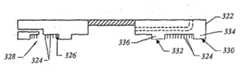
도 25에 도시된 또 다른 실시예에서 척 보디(322)는 함몰부(328) 밖의 바닥 표면(326)으로부터 돌출한 복수의 핀(324)을 포함할 수 있다. 핀(324)은 진공에 의해서 척 보디(322)에 유지되고 지지 영역(334, 336)의 표면(330, 332)에 놓인 템플릿(도시 생략)을 위한 기계적인 지지를 제공한다. 표면 영역(330, 332)은 템플릿(도시 생략)과 함께 유체 밀봉을 제공한다. 이러한 목적을 위해, 표면(330, 332)은 광학적으로 평탄하게 연마되고 핀(324)은 함몰부(328)로부터 뻗어 표면 영역(330, 332)과 공통 평면에서 끝난다. Z 방향에서 템플릿(도시 생략)의 기계적인 지지는 지지 영역(334, 336)과 핀(324)에 의해서 제공되며, 핀(324)은 전형적으로 원형 또는 정사각형의 단면을 갖는 강성의 지주이다. 공칭 진공 압력이 가해질 때 템플릿(도시 생략)상의 몰드(도시 생략)가 실질적으로 평탄하도록 핀(324)은 패턴으로 배열된다.In another embodiment shown in FIG. 25, the
도 22, 23 및 26을 참고하면, 작동시에 X-Y 평면에서 웨이퍼(30)의 정확한 측정은 단계 400에서 실행된다. 이것은 기계 영상 장치(도시 생략) 및 공지된 신호 처리 기술을 사용하여 웨이퍼(30) 상에 존재하는 그로스 정렬 기준(338)을 감지함으로써 달성될 수 있다. 단계 402에서, 영역 a-1 중의 하나의 면적이 몰드(28) 상의 오리지널 패턴의 면적보다 약간 작게 설정된다. 이것은 영역 a-1 중의 하나의 면적보다 약간 큰 패턴을 그 위에 갖도록 몰드(28)를 제조, 및/또는 예를 들어 온도를 변화시킴으로써 몰드(28)를 확장, 온도 제어 환경(도시 생략)에 몰드(28) 및 웨이퍼(30)를 놓고 특히 몰드(28) 및 웨이퍼(30)로 제조되는 재료의 열팽창 계수의 차이로 인해 발생하는 치수 변화를 야기하는 상기 환경의 온도를 변화시킴으로써 달성될 수 있다. 대안으로 또는 이와 관련하여, 영역 a-1 중의 하나의 면적이 몰드(28)상의 오리지널 패턴의 면적보다 약간 작아지도록 웨이퍼(30)의 온도가 변화, 즉 높아지거나 또는 낮아질 수 있다. 온도 변화는 웨이퍼(30)가 위치되는 온도 제어식 척 또는 받침대(도시 생략)를 사용하여 달성될 수 있다. 열적 해결방안을 논의할 경우에 본질적인 가정은 웨이퍼(30)에 대해 무의미한 것으로 인정되는 ± 0.03 ppm 뒤틀림을 나타내는 섭씨 ±0.01도 수준의 뛰어난 온도제어가 가능하다는 것이다. 대안으로, 웨이퍼(30)와 몰드(28) 모두에 대한 온도 변화는 온도 제어식 챔버(도시 생략)에 웨이퍼와 몰드를 위치시킴으로써 달성될 수 있다. 특히 이것은 열팽창 계수가 다른 재료로 웨이퍼(30)와 몰드(28)를 제조할 때 유리하다. 각각의 영역 a-1의 면적은 두개의 동일 선상의 그로스 정렬 기준(338) 사이의 거리 변화의 측정에 의해 결정될 수 있다.Referring to Figures 22, 23 and 26, an accurate measurement of the
특히, X축 또는 Y축 중 하나를 따라 동일 선상의 2개의 그로스 정렬 기준(338) 사이의 거리 변화가 측정된다. 그 후에, 이러한 거리 변화는 X축을 따라 웨이퍼(30) 상에 인접한 영역 a-1의 수로 나누어진다. 이것은 X축을 따라 웨이퍼(30)에서 치수 변화에 기여할 수 있는 영역 a-1 면적의 치수 변화를 제공한다. 필요한 경우 Y축을 따라 웨이퍼(30)의 치수 변화에 기인한 영역 a-1 면적의 변화를 결정하기 위하여 동일한 측정이 이루어질 수 있다. 그러나, 웨이퍼(30)에서의 치수 변화는 2개의 직교하는 축선인 X축 및 Y축에서 일정하다고 가정할 수 있다.In particular, the change in distance between two
단계 404에서, 압축력(F1-8 )이 몰드(28)에 작용하여 오리지널 패턴의 면적이 그 패턴과 포개지는 영역 a-1 중의 하나의 면적과 동일한 공간에 위치하고 몰드(28)상의 패턴과 영역 a-1 중의 하나 사이에 정확한 정렬을 확립한다. 이것은 두개 이상의 정렬 마크(298)가 두개 이상의 기준 마크(296)와 정렬되는 때를 결정하 기 위하여 영상 장치(도시 생략) 및 공지된 신호 처리 기술을 사용하여 실시간으로 달성될 수 있다. 단계 406에서, 정확한 정렬이 이루어지고 확대/런 아웃 에러가 감소된 후에, 손상되지 않았다면 오리지널 패턴은 몰드(28)와 포개지는 영역 a-1에 기록되어 기록 패턴을 형성한다. 웨이퍼(30) 또는 몰드(28)에서의 치수 변화가 모든 방향에서 균일하지 않을 수 있으므로 압축력(F1-8)이 동일한 크기를 가질 필요는 없다. 더욱이, 확대/런 아웃 에러는 X-Y 방향 모두에서 동일하지 않을 수 있다. 결과적으로, 압축력(F1-8)은 이러한 예외적인 것을 보상하기 위해서 상이할 수 있다. 특히, 상술한 바와 같이 액추에이터 서브-어셈블리(190)의 각각의 레버 서브-어셈블리(196)는 독립적으로 작동할 수 있다. 이것은 확대 뒤틀림뿐만 아니라 몰드상이 패턴에 존재할 수 있는 뒤틀림, 예를 들면 스큐 뒤틀림 및 키스톤 뒤틀림과 같은 직교 뒤틀림을 보상하기 위하여 몰드(28)에 상이한 힘 조합(F1-8)을 적용한다. 게다가, 확대/런 아웃 에러의 더 큰 감소를 보장하기 위해서, 몰드(28)에서의 치수 변화는 몰드(28)가 도 4의 임프린트 층(도시 생략)과 접촉한 후에 실행된다. 그러나, 이것이 반드시 필요한 것은 아니다.In
도 6, 22 및 23을 참고하면, 몰드(28)와 이에 포개지는 영역 a-1의 정렬은 몰드(28)가 임프린트 층(도시 생략)으로부터 공간적으로 이격되어 있는 상태로 이루어질 수 있다. 확대/런 아웃 에러가 전체 웨이퍼(30)에 걸쳐서 일정하다는 것을 확인하였다면, 그 다음에 힘(F1-8)의 크기는 오리지널 패턴이 기록되는 각각의 영역 a-1에 대해서 유지될 수 있다. 그러나, 확대/런 아웃 에러가 하나 이상의 영역 a- 1에 대해서 상이하다고 결정되었다면, 그 다음에 도 26에 도시된 단계 402 및 404가 오리지널 패턴이 기록되는 각각의 영역 a-1에 대해서 실행된다. 웨이퍼(30)와 몰드(28) 사이에 발생할 수 있는 상대적인 치수 변화에 한계가 있다는 것에 유의하여야 한다. 예를 들면, 영역 a-1의 면적은 몰드(28)의 구조적 완전성을 손상시키지 않고, 몰드(28)에 압축력(F1-8)이 가해질 때 몰드(28)상의 패턴이 몰드와 동일한 공간에 걸쳐 있는 면적을 한정할 수 있도록 적절한 치수를 가져야만 한다.6, 22 and 23, the alignment of the
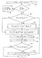
도 22, 23 및 27을 참고하면, 본 발명의 다른 실시예에 따라 X-Y 평면에서 웨이퍼(30)의 정확한 측정은 단계 500에서 실행된다. 단계 502에서, 몰드(23)상의 오리지널 패턴이 예를 들면 스큐 튀틀림, 키스톤 뒤틀림 등의 임의의 뒤틀림을 갖고 있는지 여부가 결정된다. 만약 오리지널 패턴 뒤틀림이 존재하면, 오리지널 패턴 뒤틀림을 제거하기 위하여 (F1-8)의 필요한 크기 차를 생성하도록 힘 차이가 확립되고, 단계 504에서 힘 차이를 정의한다. 이 방식에서, 스큐 튀틀림, 키스톤 뒤틀림 등은 비록 완전히 제거되지는 않더라도 원하는 오리지널 패턴을 갖는 몰드(28)를 제공하기 위하여 감소될 수 있다. 만약 오리지널 패턴에 어떠한 뒤틀림도 존재하지 않는다면, 단계 506에서 몰드(28)와 포개지는 영역 a-1중의 하나의 면적이 몰드(28)상의 패턴의 면적보다 큰지 아니진 여부가 결정된다. 만약 크다면 단계 508로 진행되고, 그렇지 않은 경우에는 단계 510으로 진행된다. 단계 510에서, 몰드(28)는 몰드에 포개지는 영역 a-1과 접촉하여 배치되고, 패턴 면적이 영역 a-1과 동일한 공간에 걸쳐 있는 것을 보장하기 위해 몰드(28)에 가해지도록 힘 차이를 포함하고 있는 압축력(F1-8)의 필요한 크기가 결정된다. 단계 512에서, 압축력(F1-8)이 몰드(28)에 가해지고 패턴이 웨이퍼(30)에 기록된다. 단계 514에서, 패턴은 웨이퍼(30)에 기록된다. 그 후에, 몰드(28)는 몰드(28)와 포개진 영역 a-1으로부터 이격되고 패턴을 기록할 웨이퍼(30) 상에 영역 a-1이 남아 있는지를 결정하는 단계 516로 진행한다. 만약 패턴을 기록할 영역 a-1이 남아 있으면 몰드(28)가 다음 영역과 포개져서 위치되는 단계 518로 진행하고 공정은 단계 506으로 진행한다. 그렇지 않으면, 공정은 단계 520에서 종료한다.Referring to Figures 22, 23 and 27, an accurate measurement of
단계 506에서 몰드(28)와 포개지는 영역 a-1이 패턴의 면적보다 더 큰 면적을 갖는 것으로 결정되었다면, 그 다음에 공정은 몰드(28) 및/또는 웨이퍼(30)의 온도가 몰드 및/또는 웨이퍼의 확장을 야기하도록 변화되는 단계 508로 진행한다. 본 실시예에서, 패턴이 몰드와 포개지는 영역 a-1의 면적보다 약간 더 크게 되도록 몰드(28)는 단계 508에서 가열된다. 그 다음, 공정은 단계 512로 계속된다.If in
이상 설명한 본 발명의 실시예는 예시적인 것이다. 본 발명의 범주에서 벗어나지 않고, 상술한 기재 내용에 대한 다양한 변경 및 개량이 이루어질 수 있다. 예를 들면, 정압의 유체 압력으로 척 본체-기판 조합에 의해서 형성된 모든 챔버에 압력을 가하는 것에 의해서, 기판은 척 본체로부터 더욱 신속하게 분리될 수 있다. 또한, 상술한 실시예는 중합가능한 재료의 액적을 침착하는 것에 의해서 임프린트 층을 형성하는 것을 채용하지 않는 현존하는 임프린트 리소그래피 프로세스에서 실시될 수 있다. 따라서, 본 발명의 범위는 상술한 기재 내용으로 제한되어서는 안 되며, 청구범위와 함께 그 등가물의 전체 범위를 참고하여 결정되어야만 한다.The embodiment of the present invention described above is illustrative. Various modifications and improvements can be made to the above teachings without departing from the scope of the invention. For example, by applying pressure to all chambers formed by the chuck body-substrate combination with a static fluid pressure, the substrate can be released more quickly from the chuck body. In addition, the embodiments described above can be practiced in existing imprint lithography processes that do not employ forming an imprint layer by depositing droplets of polymerizable material. Therefore, the scope of the present invention should not be limited to the above description but should be determined with reference to the full scope of the equivalents thereof along with the claims.
Claims (15)
Translated fromKoreanApplications Claiming Priority (5)
| Application Number | Priority Date | Filing Date | Title |
|---|---|---|---|
| US57687904P | 2004-06-03 | 2004-06-03 | |
| US60/576,879 | 2004-06-03 | ||
| US10/999,898US20050270516A1 (en) | 2004-06-03 | 2004-11-30 | System for magnification and distortion correction during nano-scale manufacturing |
| US10/999,898 | 2004-11-30 | ||
| PCT/US2005/018991WO2005121892A2 (en) | 2004-06-03 | 2005-06-01 | Apparatus, system and method to vary dimensions of a substrate during nano-scale manufacturing |
Publications (2)
| Publication Number | Publication Date |
|---|---|
| KR20070031334A KR20070031334A (en) | 2007-03-19 |
| KR101113030B1true KR101113030B1 (en) | 2012-03-14 |
Family
ID=35448519
Family Applications (1)
| Application Number | Title | Priority Date | Filing Date |
|---|---|---|---|
| KR1020067026934AExpired - LifetimeKR101113030B1 (en) | 2004-06-03 | 2005-06-01 | Apparatus, system and method to vary dimensions of a substrate during nano-scale manufacturing |
Country Status (9)
| Country | Link |
|---|---|
| US (4) | US20050270516A1 (en) |
| EP (3) | EP2207061B1 (en) |
| JP (1) | JP4688872B2 (en) |
| KR (1) | KR101113030B1 (en) |
| CN (1) | CN1981236B (en) |
| AT (2) | ATE479130T1 (en) |
| DE (1) | DE602005023153D1 (en) |
| TW (1) | TWI298816B (en) |
| WO (1) | WO2005121892A2 (en) |
Families Citing this family (110)
| Publication number | Priority date | Publication date | Assignee | Title |
|---|---|---|---|---|
| EP1352295B1 (en)* | 2000-10-12 | 2015-12-23 | Board of Regents, The University of Texas System | Template for room temperature, low pressure micro- and nano-imprint lithography |
| US20080160129A1 (en) | 2006-05-11 | 2008-07-03 | Molecular Imprints, Inc. | Template Having a Varying Thickness to Facilitate Expelling a Gas Positioned Between a Substrate and the Template |
| US7019819B2 (en) | 2002-11-13 | 2006-03-28 | Molecular Imprints, Inc. | Chucking system for modulating shapes of substrates |
| US7442336B2 (en)* | 2003-08-21 | 2008-10-28 | Molecular Imprints, Inc. | Capillary imprinting technique |
| US7077992B2 (en)* | 2002-07-11 | 2006-07-18 | Molecular Imprints, Inc. | Step and repeat imprint lithography processes |
| US8211214B2 (en) | 2003-10-02 | 2012-07-03 | Molecular Imprints, Inc. | Single phase fluid imprint lithography method |
| US20050270516A1 (en)* | 2004-06-03 | 2005-12-08 | Molecular Imprints, Inc. | System for magnification and distortion correction during nano-scale manufacturing |
| JP4574240B2 (en)* | 2004-06-11 | 2010-11-04 | キヤノン株式会社 | Processing apparatus, processing method, device manufacturing method |
| US20060062922A1 (en) | 2004-09-23 | 2006-03-23 | Molecular Imprints, Inc. | Polymerization technique to attenuate oxygen inhibition of solidification of liquids and composition therefor |
| US7630067B2 (en) | 2004-11-30 | 2009-12-08 | Molecular Imprints, Inc. | Interferometric analysis method for the manufacture of nano-scale devices |
| US20070231421A1 (en) | 2006-04-03 | 2007-10-04 | Molecular Imprints, Inc. | Enhanced Multi Channel Alignment |
| JP2006261605A (en)* | 2005-03-18 | 2006-09-28 | Canon Inc | Exposure apparatus and exposure method |
| US7442029B2 (en)* | 2005-05-16 | 2008-10-28 | Asml Netherlands B.V. | Imprint lithography |
| US7700498B2 (en)* | 2005-05-27 | 2010-04-20 | Princeton University | Self-repair and enhancement of nanostructures by liquification under guiding conditions |
| US7927089B2 (en)* | 2005-06-08 | 2011-04-19 | Canon Kabushiki Kaisha | Mold, apparatus including mold, pattern transfer apparatus, and pattern forming method |
| US8582089B2 (en)* | 2006-06-09 | 2013-11-12 | Chemimage Corporation | System and method for combined raman, SWIR and LIBS detection |
| US7906058B2 (en) | 2005-12-01 | 2011-03-15 | Molecular Imprints, Inc. | Bifurcated contact printing technique |
| MY144847A (en) | 2005-12-08 | 2011-11-30 | Molecular Imprints Inc | Method and system for double-sided patterning of substrates |
| US7670530B2 (en) | 2006-01-20 | 2010-03-02 | Molecular Imprints, Inc. | Patterning substrates employing multiple chucks |
| US7360851B1 (en) | 2006-02-15 | 2008-04-22 | Kla-Tencor Technologies Corporation | Automated pattern recognition of imprint technology |
| US20070200276A1 (en)* | 2006-02-24 | 2007-08-30 | Micron Technology, Inc. | Method for rapid printing of near-field and imprint lithographic features |
| US8012395B2 (en) | 2006-04-18 | 2011-09-06 | Molecular Imprints, Inc. | Template having alignment marks formed of contrast material |
| US8215946B2 (en) | 2006-05-18 | 2012-07-10 | Molecular Imprints, Inc. | Imprint lithography system and method |
| US20110237446A1 (en)* | 2006-06-09 | 2011-09-29 | Chemlmage Corporation | Detection of Pathogenic Microorganisms Using Fused Raman, SWIR and LIBS Sensor Data |
| US7946837B2 (en)* | 2006-10-06 | 2011-05-24 | Asml Netherlands B.V. | Imprint lithography |
| TW200842934A (en)* | 2006-12-29 | 2008-11-01 | Molecular Imprints Inc | Imprint fluid control |
| KR100843342B1 (en) | 2007-02-12 | 2008-07-03 | 삼성전자주식회사 | UV Nanoimprint Lithography Process and Apparatus |
| US20090014917A1 (en)* | 2007-07-10 | 2009-01-15 | Molecular Imprints, Inc. | Drop Pattern Generation for Imprint Lithography |
| US7837907B2 (en)* | 2007-07-20 | 2010-11-23 | Molecular Imprints, Inc. | Alignment system and method for a substrate in a nano-imprint process |
| NL1036034A1 (en)* | 2007-10-11 | 2009-04-15 | Asml Netherlands Bv | Imprint lithography. |
| US8119052B2 (en)* | 2007-11-02 | 2012-02-21 | Molecular Imprints, Inc. | Drop pattern generation for imprint lithography |
| US20090147237A1 (en)* | 2007-12-05 | 2009-06-11 | Molecular Imprints, Inc. | Spatial Phase Feature Location |
| JP4909913B2 (en)* | 2008-01-10 | 2012-04-04 | 株式会社東芝 | Imprint mask manufacturing method and semiconductor device manufacturing method |
| US8361371B2 (en)* | 2008-02-08 | 2013-01-29 | Molecular Imprints, Inc. | Extrusion reduction in imprint lithography |
| US20090212012A1 (en)* | 2008-02-27 | 2009-08-27 | Molecular Imprints, Inc. | Critical dimension control during template formation |
| JP5588358B2 (en)* | 2008-02-29 | 2014-09-10 | コーニング インコーポレイテッド | Kinematic optical mount |
| WO2009129441A2 (en)* | 2008-04-17 | 2009-10-22 | Massachusetts Institute Of Technology | Symmetric thermocentric flexure with minimal yaw error motion |
| JP5123059B2 (en)* | 2008-06-09 | 2013-01-16 | 株式会社東芝 | Manufacturing method of semiconductor device |
| WO2010021291A1 (en)* | 2008-08-22 | 2010-02-25 | コニカミノルタオプト株式会社 | Substrate manufacturing method, substrate manufactured by the substrate manufacturing method and magnetic recording medium using the substrate |
| US8512797B2 (en)* | 2008-10-21 | 2013-08-20 | Molecular Imprints, Inc. | Drop pattern generation with edge weighting |
| US8586126B2 (en) | 2008-10-21 | 2013-11-19 | Molecular Imprints, Inc. | Robust optimization to generate drop patterns in imprint lithography which are tolerant of variations in drop volume and drop placement |
| US8652393B2 (en) | 2008-10-24 | 2014-02-18 | Molecular Imprints, Inc. | Strain and kinetics control during separation phase of imprint process |
| US8345242B2 (en)* | 2008-10-28 | 2013-01-01 | Molecular Imprints, Inc. | Optical system for use in stage control |
| US20100112220A1 (en)* | 2008-11-03 | 2010-05-06 | Molecular Imprints, Inc. | Dispense system set-up and characterization |
| US8231821B2 (en)* | 2008-11-04 | 2012-07-31 | Molecular Imprints, Inc. | Substrate alignment |
| US8432548B2 (en)* | 2008-11-04 | 2013-04-30 | Molecular Imprints, Inc. | Alignment for edge field nano-imprinting |
| US8553207B2 (en)* | 2008-12-31 | 2013-10-08 | Asml Holdings N.V. | Optically compensated unidirectional reticle bender |
| WO2010111307A1 (en)* | 2009-03-23 | 2010-09-30 | Intevac, Inc. | A process for optimization of island to trench ratio in patterned media |
| NL2004735A (en) | 2009-07-06 | 2011-01-10 | Asml Netherlands Bv | Imprint lithography apparatus and method. |
| US20110084417A1 (en)* | 2009-10-08 | 2011-04-14 | Molecular Imprints, Inc. | Large area linear array nanoimprinting |
| DE102010007970A1 (en) | 2010-02-15 | 2011-08-18 | Suss MicroTec Lithography GmbH, 85748 | Method and device for active wedge error compensation between two objects which can be positioned substantially parallel to one another |
| JP5637785B2 (en)* | 2010-09-06 | 2014-12-10 | キヤノン株式会社 | Original plate and method of manufacturing article using the same |
| JP5822597B2 (en)* | 2010-10-01 | 2015-11-24 | キヤノン株式会社 | Imprint apparatus and article manufacturing method using the same |
| JP5744548B2 (en)* | 2011-02-02 | 2015-07-08 | キヤノン株式会社 | Holding device, imprint apparatus using the same, and article manufacturing method |
| WO2012172755A1 (en)* | 2011-06-16 | 2012-12-20 | パナソニック株式会社 | Sheet, mold, and manufacturing method thereof |
| JP5498448B2 (en)* | 2011-07-21 | 2014-05-21 | 株式会社東芝 | Imprint method and imprint system |
| JP5694889B2 (en)* | 2011-09-29 | 2015-04-01 | 富士フイルム株式会社 | Nanoimprint method, nanoimprint apparatus used therefor, and manufacturing method of patterned substrate |
| JP6140966B2 (en) | 2011-10-14 | 2017-06-07 | キヤノン株式会社 | Imprint apparatus and article manufacturing method using the same |
| JP5686779B2 (en) | 2011-10-14 | 2015-03-18 | キヤノン株式会社 | Imprint apparatus and article manufacturing method using the same |
| JP5865528B2 (en)* | 2011-10-14 | 2016-02-17 | キヤノン株式会社 | Imprint apparatus, imprint method, and device manufacturing method |
| JP2013098291A (en)* | 2011-10-31 | 2013-05-20 | Canon Inc | Imprint device, imprint method, and object manufacturing method using the same |
| JP6021606B2 (en)* | 2011-11-28 | 2016-11-09 | キヤノン株式会社 | Imprint apparatus, article manufacturing method using the same, and imprint method |
| JP6304934B2 (en)* | 2012-05-08 | 2018-04-04 | キヤノン株式会社 | Imprint apparatus and article manufacturing method |
| WO2014024958A1 (en)* | 2012-08-09 | 2014-02-13 | 大日本印刷株式会社 | Production method for minute convex-shaped pattern structure and minute convex-shaped pattern structure production system |
| JP5960198B2 (en) | 2013-07-02 | 2016-08-02 | キヤノン株式会社 | Pattern forming method, lithographic apparatus, lithographic system, and article manufacturing method |
| JP6497839B2 (en) | 2013-11-07 | 2019-04-10 | キヤノン株式会社 | Imprint apparatus and article manufacturing method |
| WO2015070054A1 (en)* | 2013-11-08 | 2015-05-14 | Canon Nanotechnologies, Inc. | Low contact imprint lithography template chuck system for improved overlay correction |
| JP6294680B2 (en) | 2014-01-24 | 2018-03-14 | キヤノン株式会社 | Imprint apparatus and article manufacturing method |
| JP6294686B2 (en)* | 2014-02-04 | 2018-03-14 | キヤノン株式会社 | Imprint apparatus, imprint method, and article manufacturing method |
| JP2017514643A (en) | 2014-03-25 | 2017-06-08 | バイオボット、インコーポレイテッド | Methods, devices and systems for the production of materials and tissues utilizing electromagnetic radiation |
| JP6317620B2 (en)* | 2014-05-02 | 2018-04-25 | キヤノン株式会社 | Imprint method, imprint apparatus, and article manufacturing method |
| EP2960059B1 (en) | 2014-06-25 | 2018-10-24 | Universal Display Corporation | Systems and methods of modulating flow during vapor jet deposition of organic materials |
| US11220737B2 (en) | 2014-06-25 | 2022-01-11 | Universal Display Corporation | Systems and methods of modulating flow during vapor jet deposition of organic materials |
| US11267012B2 (en)* | 2014-06-25 | 2022-03-08 | Universal Display Corporation | Spatial control of vapor condensation using convection |
| JP6385177B2 (en)* | 2014-07-16 | 2018-09-05 | キヤノン株式会社 | Mold, imprint apparatus, and article manufacturing method |
| US10331027B2 (en) | 2014-09-12 | 2019-06-25 | Canon Kabushiki Kaisha | Imprint apparatus, imprint system, and method of manufacturing article |
| CN104476763B (en)* | 2014-11-10 | 2017-07-07 | 镇江中化聚氨酯工业设备有限公司 | The indent equipment of polyurethane heat-insulation energy-conserving plate material |
| JP6437387B2 (en)* | 2015-05-25 | 2018-12-12 | 東芝メモリ株式会社 | Substrate flattening method |
| US10566534B2 (en) | 2015-10-12 | 2020-02-18 | Universal Display Corporation | Apparatus and method to deliver organic material via organic vapor-jet printing (OVJP) |
| JP2017152673A (en) | 2015-11-05 | 2017-08-31 | ボード・オブ・リージェンツ, ジ・ユニバーシティー・オブ・テキサス・システム | Multi-field overlay control in jet and flash imprint lithography |
| JP6677495B2 (en)* | 2015-12-04 | 2020-04-08 | キヤノン株式会社 | Imprint apparatus and article manufacturing method |
| CN105607415B (en)* | 2016-02-25 | 2019-10-25 | 中国科学技术大学 | A nano-imprint head and imprinting equipment with the nano-imprint head |
| JP6685821B2 (en)* | 2016-04-25 | 2020-04-22 | キヤノン株式会社 | Measuring apparatus, imprint apparatus, article manufacturing method, light quantity determination method, and light quantity adjustment method |
| US9993962B2 (en) | 2016-05-23 | 2018-06-12 | Canon Kabushiki Kaisha | Method of imprinting to correct for a distortion within an imprint system |
| JP6882027B2 (en)* | 2017-03-16 | 2021-06-02 | キヤノン株式会社 | Imprint equipment and article manufacturing method |
| US10534259B2 (en)* | 2017-03-28 | 2020-01-14 | Canon Kabushiki Kaisha | Method and system for imprint force control |
| WO2018187472A1 (en)* | 2017-04-04 | 2018-10-11 | Allevi, Inc. | Multi-headed auto-calibrating bioprinter with heads that heat, cool, and crosslink |
| US10998190B2 (en) | 2017-04-17 | 2021-05-04 | Canon Kabushiki Kaisha | Imprint apparatus and method of manufacturing article |
| US11175598B2 (en) | 2017-06-30 | 2021-11-16 | Canon Kabushiki Kaisha | Imprint apparatus and method of manufacturing article |
| JP6865650B2 (en) | 2017-07-27 | 2021-04-28 | キヤノン株式会社 | Imprint equipment and article manufacturing method |
| US10996560B2 (en) | 2017-07-31 | 2021-05-04 | Canon Kabushiki Kaisha | Real-time correction of template deformation in nanoimprint lithography |
| US10866510B2 (en) | 2017-07-31 | 2020-12-15 | Canon Kabushiki Kaisha | Overlay improvement in nanoimprint lithography |
| US10409178B2 (en) | 2017-12-18 | 2019-09-10 | Canon Kabushiki Kaisha | Alignment control in nanoimprint lithography based on real-time system identification |
| US10996561B2 (en) | 2017-12-26 | 2021-05-04 | Canon Kabushiki Kaisha | Nanoimprint lithography with a six degrees-of-freedom imprint head module |
| JP7222623B2 (en) | 2018-07-23 | 2023-02-15 | キヤノン株式会社 | Pattern forming method and article manufacturing method |
| JP7204457B2 (en) | 2018-12-06 | 2023-01-16 | キヤノン株式会社 | IMPRINT APPARATUS, IMPRINT METHOD, AND PRODUCT MANUFACTURING METHOD |
| JP7254564B2 (en) | 2019-03-05 | 2023-04-10 | キヤノン株式会社 | IMPRINT APPARATUS, IMPRINT METHOD, AND ARTICLE MANUFACTURING METHOD |
| JP7286391B2 (en) | 2019-04-16 | 2023-06-05 | キヤノン株式会社 | IMPRINT APPARATUS AND ARTICLE MANUFACTURING METHOD |
| NL2023051B1 (en)* | 2019-05-02 | 2020-11-23 | Suss Microtec Lithography Gmbh | Framework for a replication device, replication device as well as method for producing nanostructured and/or microstructured components by means of a 5 replication device |
| JP7256684B2 (en) | 2019-05-14 | 2023-04-12 | キヤノン株式会社 | Imprinting apparatus, imprinting method and article manufacturing method |
| KR102168476B1 (en)* | 2019-08-27 | 2020-10-21 | 한국기계연구원 | Fabricating apparatus and method for transparent stamp, the same transparent stamp made by the apparatus and imprint lithography method with the same transparent stamp |
| US11994797B2 (en) | 2020-10-28 | 2024-05-28 | Canon Kabushiki Kaisha | System and method for shaping a film with a scaled calibration measurement parameter |
| US11815811B2 (en) | 2021-03-23 | 2023-11-14 | Canon Kabushiki Kaisha | Magnification ramp scheme to mitigate template slippage |
| WO2023001802A1 (en)* | 2021-07-21 | 2023-01-26 | Koninklijke Philips N.V. | Imprinting apparatus |
| EP4123375A1 (en)* | 2021-07-21 | 2023-01-25 | Koninklijke Philips N.V. | Imprinting apparatus |
| JP7703397B2 (en)* | 2021-08-25 | 2025-07-07 | キヤノン株式会社 | Imprinting apparatus, article manufacturing method, and computer program |
| US12269282B2 (en) | 2021-10-15 | 2025-04-08 | Canon Kabushiki Kaisha | Nanoimprint lithography template with peripheral pockets, system of using the template, and method of using the template |
| US12124165B2 (en) | 2021-10-25 | 2024-10-22 | Canon Kabushiki Kaisha | Apparatus and method for optimizing actuator forces |
| US12040584B2 (en)* | 2021-12-08 | 2024-07-16 | Eagle Technology, Llc | Optical system for use with a vacuum chamber and associated method |
| JP2023118658A (en)* | 2022-02-15 | 2023-08-25 | キヤノン株式会社 | Imprint device, foreign matter removal method, and manufacturing method for article |
Citations (3)
| Publication number | Priority date | Publication date | Assignee | Title |
|---|---|---|---|---|
| US20040027462A1 (en)* | 2000-09-25 | 2004-02-12 | Hing Paul Anthony | Image sensor device, apparatus and method for optical measurements |
| JP2007033676A (en)* | 2005-07-25 | 2007-02-08 | Ricoh Co Ltd | Polarization conversion optical element, light modulation module, and projection-type image display device |
| US20110159446A1 (en)* | 2009-04-24 | 2011-06-30 | First Principles Technology, Llc | Plasmon head with hydrostatic gas bearing for near field photolithography |
Family Cites Families (128)
| Publication number | Priority date | Publication date | Assignee | Title |
|---|---|---|---|---|
| US137734A (en)* | 1873-04-08 | Improvement in fertilizing-distributers | ||
| US110856A (en)* | 1871-01-10 | Improvement in devices for securing the tines of hay-tedders | ||
| US197843A (en)* | 1877-12-04 | Improvement in weather-strips | ||
| US80471A (en)* | 1868-07-28 | Improved lubricating compound | ||
| US42027A (en)* | 1864-03-22 | Improvement in huller and screen | ||
| US118809A (en)* | 1871-09-12 | Improvement in blacking apparatus and bootjack combined | ||
| US13118A (en)* | 1855-06-19 | Burgh | ||
| US86793A (en)* | 1869-02-09 | Improvement in the manufacture of gas from petroleum | ||
| US150398A (en)* | 1874-05-05 | Improvement in baby-walkers | ||
| US7799A (en)* | 1850-11-26 | Improved method of securing rails of railroads | ||
| US146792A (en)* | 1874-01-27 | Improvement in rotary printing presses for cards and tickets | ||
| US46288A (en)* | 1865-02-07 | Improvement in clasps for wearing apparel | ||
| US177319A (en)* | 1876-05-16 | Improvement in rolling-pins | ||
| US192041A (en)* | 1877-06-12 | Improvement in steam-engine valves | ||
| US90611A (en)* | 1869-05-25 | Improvement in fence-post socket | ||
| US6343A (en)* | 1849-04-17 | Moetising-machine | ||
| US132482A (en)* | 1872-10-22 | Improvement in buckles | ||
| US124566A (en)* | 1872-03-12 | Improvement in combined tools | ||
| US21866A (en)* | 1858-10-26 | Improvement in tools for manufacturing wire riddles | ||
| US8334A (en)* | 1851-09-02 | Drying and oxidizing colored goods | ||
| US80472A (en)* | 1868-07-28 | Thomas gibson | ||
| US112861A (en)* | 1871-03-21 | Improvement in gauges for saw-tables | ||
| US22888A (en)* | 1859-02-08 | Process op manueacttrkeng catistic alkalis | ||
| US179354A (en)* | 1876-06-27 | Improvement in culinary vessels | ||
| US34329A (en)* | 1862-02-04 | Improved iron ponton | ||
| US156108A (en)* | 1874-10-20 | Improvement in methods of | ||
| US18190A (en)* | 1857-09-15 | Improvement in making paper-pulp from ivory | ||
| US21254A (en)* | 1858-08-24 | Improvement in machines for cutting up cornstalks in the field | ||
| US167117A (en)* | 1875-08-24 | piper | ||
| US36201A (en)* | 1862-08-19 | Napoleon aubin | ||
| US9673A (en)* | 1853-04-19 | Machine for rolling- bar-iron | ||
| US92261A (en)* | 1869-07-06 | Improvement in countersink | ||
| US33515A (en)* | 1861-10-22 | Improvement in carriage-curtain fastenings | ||
| US53146A (en)* | 1866-03-13 | 1866-03-13 | Improvement in time-pieces | |
| DE1160302B (en) | 1962-08-29 | 1963-12-27 | Agfa Ag | Photographic material |
| US3783520A (en)* | 1970-09-28 | 1974-01-08 | Bell Telephone Labor Inc | High accuracy alignment procedure utilizing moire patterns |
| GB1578259A (en)* | 1977-05-11 | 1980-11-05 | Philips Electronic Associated | Methods of manufacturing solid-state devices apparatus for use therein and devices manufactured thereby |
| US4326805A (en) | 1980-04-11 | 1982-04-27 | Bell Telephone Laboratories, Incorporated | Method and apparatus for aligning mask and wafer members |
| US4492554A (en) | 1980-08-26 | 1985-01-08 | Corn States Metal Fabricators, Inc. | Valve unit for a mold vent |
| FR2538923A1 (en)* | 1982-12-30 | 1984-07-06 | Thomson Csf | METHOD AND DEVICE FOR OPTICALLY ALIGNING PATTERNS IN TWO PLANS RECONCILED IN AN EXPOSURE APPARATUS COMPRISING A DIVERGENT RADIATION SOURCE |
| US4512848A (en)* | 1984-02-06 | 1985-04-23 | Exxon Research And Engineering Co. | Procedure for fabrication of microstructures over large areas using physical replication |
| US4724222A (en) | 1986-04-28 | 1988-02-09 | American Telephone And Telegraph Company, At&T Bell Laboratories | Wafer chuck comprising a curved reference surface |
| KR900004269B1 (en)* | 1986-06-11 | 1990-06-18 | 가부시기가이샤 도시바 | Method and device for positioing 1st body and 2nd body |
| US4929083A (en) | 1986-06-19 | 1990-05-29 | Xerox Corporation | Focus and overlay characterization and optimization for photolithographic exposure |
| US4731155A (en)* | 1987-04-15 | 1988-03-15 | General Electric Company | Process for forming a lithographic mask |
| US5028366A (en)* | 1988-01-12 | 1991-07-02 | Air Products And Chemicals, Inc. | Water based mold release compositions for making molded polyurethane foam |
| EP0355496A3 (en)* | 1988-08-15 | 1990-10-10 | Sumitomo Heavy Industries Co., Ltd. | Position detector employing a sector fresnel zone plate |
| JP2546350B2 (en)* | 1988-09-09 | 1996-10-23 | キヤノン株式会社 | Alignment device |
| US4887283A (en) | 1988-09-27 | 1989-12-12 | Mitsubishi Denki Kabushiki Kaisha | X-ray mask and exposure method employing the same |
| JP2704001B2 (en)* | 1989-07-18 | 1998-01-26 | キヤノン株式会社 | Position detection device |
| US4964145A (en) | 1989-07-24 | 1990-10-16 | International Business Machines Corporation | System for magnification correction of conductive X-ray lithography mask substrates |
| EP0480616B1 (en)* | 1990-10-08 | 1997-08-20 | Canon Kabushiki Kaisha | Projection exposure apparatus with an aberration compensation device of a projection lens |
| JP2694043B2 (en)* | 1990-10-08 | 1997-12-24 | キヤノン株式会社 | Projection type exposure system |
| US5072126A (en) | 1990-10-31 | 1991-12-10 | International Business Machines Corporation | Promixity alignment using polarized illumination and double conjugate projection lens |
| US5155749A (en) | 1991-03-28 | 1992-10-13 | International Business Machines Corporation | Variable magnification mask for X-ray lithography |
| US5204739A (en) | 1992-02-07 | 1993-04-20 | Karl Suss America, Inc. | Proximity mask alignment using a stored video image |
| EP0568478A1 (en) | 1992-04-29 | 1993-11-03 | International Business Machines Corporation | Darkfield alignment system using a confocal spatial filter |
| US5601641A (en)* | 1992-07-21 | 1997-02-11 | Tse Industries, Inc. | Mold release composition with polybutadiene and method of coating a mold core |
| JP2821073B2 (en) | 1992-12-18 | 1998-11-05 | 松下電器産業株式会社 | Gap control device and gap control method |
| DE69405451T2 (en)* | 1993-03-16 | 1998-03-12 | Koninkl Philips Electronics Nv | Method and device for producing a structured relief image from cross-linked photoresist on a flat substrate surface |
| US5414514A (en)* | 1993-06-01 | 1995-05-09 | Massachusetts Institute Of Technology | On-axis interferometric alignment of plates using the spatial phase of interference patterns |
| JP3402681B2 (en)* | 1993-06-02 | 2003-05-06 | サンエー技研株式会社 | Positioning method in exposure |
| DE59305884D1 (en)* | 1993-07-01 | 1997-04-24 | Sulzer Orthopaedie Ag | Metal filler for bone cavities |
| US6776094B1 (en)* | 1993-10-04 | 2004-08-17 | President & Fellows Of Harvard College | Kit For Microcontact Printing |
| KR0157279B1 (en)* | 1994-03-15 | 1999-05-01 | 모리시타 요이찌 | Exposure apparatus for transferring a mask pattern onto a substrate |
| US5563684A (en) | 1994-11-30 | 1996-10-08 | Sgs-Thomson Microelectronics, Inc. | Adaptive wafer modulator for placing a selected pattern on a semiconductor wafer |
| US5504793A (en) | 1995-02-17 | 1996-04-02 | Loral Federal Systems Company | Magnification correction for 1-X proximity X-Ray lithography |
| US5849209A (en)* | 1995-03-31 | 1998-12-15 | Johnson & Johnson Vision Products, Inc. | Mold material made with additives |
| US5808742A (en)* | 1995-05-31 | 1998-09-15 | Massachusetts Institute Of Technology | Optical alignment apparatus having multiple parallel alignment marks |
| US5849222A (en)* | 1995-09-29 | 1998-12-15 | Johnson & Johnson Vision Products, Inc. | Method for reducing lens hole defects in production of contact lens blanks |
| US5545570A (en) | 1995-09-29 | 1996-08-13 | Taiwan Semiconductor Manufacturing Company | Method of inspecting first layer overlay shift in global alignment process |
| US5820894A (en) | 1995-10-06 | 1998-10-13 | Mcdonnell Douglas Corporation | Method and apparatus for consolidating a workpiece at elevated temperature |
| US6309580B1 (en)* | 1995-11-15 | 2001-10-30 | Regents Of The University Of Minnesota | Release surfaces, particularly for use in nanoimprint lithography |
| US5772905A (en)* | 1995-11-15 | 1998-06-30 | Regents Of The University Of Minnesota | Nanoimprint lithography |
| US6518189B1 (en)* | 1995-11-15 | 2003-02-11 | Regents Of The University Of Minnesota | Method and apparatus for high density nanostructures |
| US6482742B1 (en)* | 2000-07-18 | 2002-11-19 | Stephen Y. Chou | Fluid pressure imprint lithography |
| JP3305188B2 (en)* | 1996-02-07 | 2002-07-22 | キヤノン株式会社 | Master, master holding apparatus, exposure apparatus using the same, and device manufacturing method |
| US5854819A (en)* | 1996-02-07 | 1998-12-29 | Canon Kabushiki Kaisha | Mask supporting device and correction method therefor, and exposure apparatus and device producing method utilizing the same |
| JP2842362B2 (en) | 1996-02-29 | 1999-01-06 | 日本電気株式会社 | Superposition measurement method |
| US20030179354A1 (en) | 1996-03-22 | 2003-09-25 | Nikon Corporation | Mask-holding apparatus for a light exposure apparatus and related scanning-exposure method |
| US6019156A (en)* | 1996-05-09 | 2000-02-01 | Kelley Company, Inc. | Roll-up door |
| US5802914A (en)* | 1996-05-30 | 1998-09-08 | Eastman Kodak Company | Alignment mechanism using flexures |
| JPH10172897A (en)* | 1996-12-05 | 1998-06-26 | Nikon Corp | Substrate adapter, substrate holding device and substrate holding method |
| US6049373A (en)* | 1997-02-28 | 2000-04-11 | Sumitomo Heavy Industries, Ltd. | Position detection technique applied to proximity exposure |
| US6069931A (en)* | 1997-02-28 | 2000-05-30 | Canon Kabushiki Kaisha | Mask structure and mask holding mechanism for exposure apparatus |
| JP3296239B2 (en)* | 1997-03-27 | 2002-06-24 | ウシオ電機株式会社 | Proximity exposure apparatus with gap setting mechanism |
| JP3450648B2 (en)* | 1997-05-09 | 2003-09-29 | キヤノン株式会社 | Magnification correction apparatus, X-ray exposure apparatus equipped with magnification correction apparatus, and device manufacturing method |
| US5877861A (en) | 1997-11-14 | 1999-03-02 | International Business Machines Corporation | Method for overlay control system |
| JP3535749B2 (en) | 1997-12-10 | 2004-06-07 | キヤノン株式会社 | Stage apparatus, exposure apparatus, and device manufacturing method |
| US6019166A (en) | 1997-12-30 | 2000-02-01 | Intel Corporation | Pickup chuck with an integral heatsink |
| US6239590B1 (en) | 1998-05-26 | 2001-05-29 | Micron Technology, Inc. | Calibration target for calibrating semiconductor wafer test systems |
| JP3780700B2 (en)* | 1998-05-26 | 2006-05-31 | セイコーエプソン株式会社 | Pattern forming method, pattern forming apparatus, pattern forming plate, pattern forming plate manufacturing method, color filter manufacturing method, conductive film manufacturing method, and liquid crystal panel manufacturing method |
| US6150231A (en)* | 1998-06-15 | 2000-11-21 | Siemens Aktiengesellschaft | Overlay measurement technique using moire patterns |
| US6713238B1 (en)* | 1998-10-09 | 2004-03-30 | Stephen Y. Chou | Microscale patterning and articles formed thereby |
| JP4846888B2 (en)* | 1998-12-01 | 2011-12-28 | キヤノン株式会社 | Alignment method |
| US6388755B1 (en)* | 1998-12-03 | 2002-05-14 | Advanced Optical Technologies, Inc. | Wireless position and orientation detecting system |
| US6334960B1 (en)* | 1999-03-11 | 2002-01-01 | Board Of Regents, The University Of Texas System | Step and flash imprint lithography |
| FR2792246B1 (en) | 1999-04-16 | 2001-06-22 | Aerospatiale | SHAPING TOOLS FOR POLYMERIZING PROFILES OF COMPOSITE MATERIALS |
| US6522411B1 (en)* | 1999-05-25 | 2003-02-18 | Massachusetts Institute Of Technology | Optical gap measuring apparatus and method having two-dimensional grating mark with chirp in one direction |
| US6517995B1 (en)* | 1999-09-14 | 2003-02-11 | Massachusetts Institute Of Technology | Fabrication of finely featured devices by liquid embossing |
| ATE294648T1 (en)* | 1999-12-23 | 2005-05-15 | Univ Massachusetts | METHOD FOR PRODUCING SUBMICRON PATTERNS ON FILM |
| JP2001358056A (en) | 2000-06-15 | 2001-12-26 | Canon Inc | Exposure equipment |
| AU2001273491A1 (en) | 2000-07-16 | 2002-02-05 | Board Of Regents, The University Of Texas System | High-resolution overlay alignment methods and systems for imprint lithography |
| AU2001286573A1 (en) | 2000-08-21 | 2002-03-04 | Board Of Regents, The University Of Texas System | Flexure based macro motion translation stage |
| US6451705B1 (en)* | 2000-08-31 | 2002-09-17 | Micron Technology, Inc. | Self-aligned PECVD etch mask |
| EP1352295B1 (en)* | 2000-10-12 | 2015-12-23 | Board of Regents, The University of Texas System | Template for room temperature, low pressure micro- and nano-imprint lithography |
| WO2002047139A2 (en) | 2000-12-04 | 2002-06-13 | Ebara Corporation | Methode of forming a copper film on a substrate |
| US6489068B1 (en)* | 2001-02-21 | 2002-12-03 | Advanced Micro Devices, Inc. | Process for observing overlay errors on lithographic masks |
| US6387787B1 (en)* | 2001-03-02 | 2002-05-14 | Motorola, Inc. | Lithographic template and method of formation and use |
| US6791669B2 (en)* | 2001-04-12 | 2004-09-14 | Nikon Corporation | Positioning device and exposure apparatus including the same |
| US6383888B1 (en)* | 2001-04-18 | 2002-05-07 | Advanced Micro Devices, Inc. | Method and apparatus for selecting wafer alignment marks based on film thickness variation |
| US6847433B2 (en) | 2001-06-01 | 2005-01-25 | Agere Systems, Inc. | Holder, system, and process for improving overlay in lithography |
| DE20109656U1 (en)* | 2001-06-11 | 2002-10-24 | Stabila-Messgeräte Gustav Ullrich GmbH & Co KG, 76855 Annweiler | spirit level |
| US6963878B2 (en)* | 2001-09-24 | 2005-11-08 | Microsoft Corporation | Generating a focused data set from an original data set |
| CA2482566C (en) | 2002-04-16 | 2010-07-20 | Princeton University | Gradient structures interfacing microfluidics and nanofluidics, methods for fabrication and uses thereof |
| US7019819B2 (en) | 2002-11-13 | 2006-03-28 | Molecular Imprints, Inc. | Chucking system for modulating shapes of substrates |
| US6936194B2 (en) | 2002-09-05 | 2005-08-30 | Molecular Imprints, Inc. | Functional patterning material for imprint lithography processes |
| US20040065252A1 (en) | 2002-10-04 | 2004-04-08 | Sreenivasan Sidlgata V. | Method of forming a layer on a substrate to facilitate fabrication of metrology standards |
| US8349241B2 (en) | 2002-10-04 | 2013-01-08 | Molecular Imprints, Inc. | Method to arrange features on a substrate to replicate features having minimal dimensional variability |
| US6665119B1 (en) | 2002-10-15 | 2003-12-16 | Eastman Kodak Company | Wire grid polarizer |
| US6929762B2 (en) | 2002-11-13 | 2005-08-16 | Molecular Imprints, Inc. | Method of reducing pattern distortions during imprint lithography processes |
| US6980282B2 (en) | 2002-12-11 | 2005-12-27 | Molecular Imprints, Inc. | Method for modulating shapes of substrates |
| WO2004044651A1 (en) | 2002-11-13 | 2004-05-27 | Molecular Imprints, Inc. | A chucking system and method for modulating shapes of substrates |
| US6871558B2 (en)* | 2002-12-12 | 2005-03-29 | Molecular Imprints, Inc. | Method for determining characteristics of substrate employing fluid geometries |
| MY136129A (en) | 2002-12-13 | 2008-08-29 | Molecular Imprints Inc | Magnification correction employing out-of-plane distortion of a substrate |
| US6770852B1 (en)* | 2003-02-27 | 2004-08-03 | Lam Research Corporation | Critical dimension variation compensation across a wafer by means of local wafer temperature control |
| US7150622B2 (en) | 2003-07-09 | 2006-12-19 | Molecular Imprints, Inc. | Systems for magnification and distortion correction for imprint lithography processes |
| US20050270516A1 (en) | 2004-06-03 | 2005-12-08 | Molecular Imprints, Inc. | System for magnification and distortion correction during nano-scale manufacturing |
- 2004
- 2004-11-30USUS10/999,898patent/US20050270516A1/ennot_activeAbandoned
- 2005
- 2005-06-01CNCN2005800229753Apatent/CN1981236B/ennot_activeExpired - Lifetime
- 2005-06-01KRKR1020067026934Apatent/KR101113030B1/ennot_activeExpired - Lifetime
- 2005-06-01JPJP2007515470Apatent/JP4688872B2/ennot_activeExpired - Lifetime
- 2005-06-01ATAT05768764Tpatent/ATE479130T1/enactive
- 2005-06-01EPEP10160309Apatent/EP2207061B1/ennot_activeExpired - Lifetime
- 2005-06-01WOPCT/US2005/018991patent/WO2005121892A2/enactiveApplication Filing
- 2005-06-01USUS11/142,834patent/US7420654B2/enactiveActive
- 2005-06-01EPEP05768764Apatent/EP1754108B1/ennot_activeExpired - Lifetime
- 2005-06-01EPEP10182998.4Apatent/EP2267531B1/ennot_activeExpired - Lifetime
- 2005-06-01USUS11/142,808patent/US7298456B2/ennot_activeExpired - Lifetime
- 2005-06-01ATAT10160309Tpatent/ATE534937T1/enactive
- 2005-06-01USUS11/142,839patent/US7170589B2/ennot_activeExpired - Lifetime
- 2005-06-01DEDE602005023153Tpatent/DE602005023153D1/ennot_activeExpired - Lifetime
- 2005-06-02TWTW094118140Apatent/TWI298816B/ennot_activeIP Right Cessation
Patent Citations (3)
| Publication number | Priority date | Publication date | Assignee | Title |
|---|---|---|---|---|
| US20040027462A1 (en)* | 2000-09-25 | 2004-02-12 | Hing Paul Anthony | Image sensor device, apparatus and method for optical measurements |
| JP2007033676A (en)* | 2005-07-25 | 2007-02-08 | Ricoh Co Ltd | Polarization conversion optical element, light modulation module, and projection-type image display device |
| US20110159446A1 (en)* | 2009-04-24 | 2011-06-30 | First Principles Technology, Llc | Plasmon head with hydrostatic gas bearing for near field photolithography |
Also Published As
| Publication number | Publication date |
|---|---|
| ATE479130T1 (en) | 2010-09-15 |
| EP2207061B1 (en) | 2011-11-23 |
| EP1754108B1 (en) | 2010-08-25 |
| JP2008504141A (en) | 2008-02-14 |
| US7298456B2 (en) | 2007-11-20 |
| DE602005023153D1 (en) | 2010-10-07 |
| WO2005121892A2 (en) | 2005-12-22 |
| CN1981236A (en) | 2007-06-13 |
| EP2207061A2 (en) | 2010-07-14 |
| ATE534937T1 (en) | 2011-12-15 |
| TWI298816B (en) | 2008-07-11 |
| KR20070031334A (en) | 2007-03-19 |
| EP1754108A2 (en) | 2007-02-21 |
| EP1754108A4 (en) | 2007-10-24 |
| JP4688872B2 (en) | 2011-05-25 |
| WO2005121892A3 (en) | 2006-05-04 |
| CN1981236B (en) | 2010-04-21 |
| US20060001194A1 (en) | 2006-01-05 |
| EP2267531A3 (en) | 2011-01-05 |
| TW200611062A (en) | 2006-04-01 |
| US20060001857A1 (en) | 2006-01-05 |
| EP2207061A3 (en) | 2010-09-01 |
| EP2267531A2 (en) | 2010-12-29 |
| US20050270516A1 (en) | 2005-12-08 |
| US7170589B2 (en) | 2007-01-30 |
| EP2267531B1 (en) | 2016-08-10 |
| US20050269745A1 (en) | 2005-12-08 |
| US7420654B2 (en) | 2008-09-02 |
Similar Documents
| Publication | Publication Date | Title |
|---|---|---|
| KR101113030B1 (en) | Apparatus, system and method to vary dimensions of a substrate during nano-scale manufacturing | |
| JP4391420B2 (en) | Chuck system and method for adjusting substrate shape | |
| JP5325914B2 (en) | Automated liquid dispensing method and system for transfer lithography process | |
| JP4594305B2 (en) | System for correcting magnification and distortion in imprint lithography processes | |
| US8016277B2 (en) | Flexure based macro motion translation stage | |
| JP4512167B2 (en) | Transfer lithography system having a template and method for aligning a substrate and a template | |
| US7019819B2 (en) | Chucking system for modulating shapes of substrates | |
| KR101031528B1 (en) | Templates for room temperature low pressure micro- and nano-imprint lithography | |
| KR20030040378A (en) | Methods for high-precision gap and orientation sensing between a transparent template and substrate for imprint lithography | |
| WO2005119802A2 (en) | Adaptive shape substrate support system and method |
Legal Events
| Date | Code | Title | Description |
|---|---|---|---|
| PA0105 | International application | Patent event date:20061221 Patent event code:PA01051R01D Comment text:International Patent Application | |
| PG1501 | Laying open of application | ||
| A201 | Request for examination | ||
| PA0201 | Request for examination | Patent event code:PA02012R01D Patent event date:20090508 Comment text:Request for Examination of Application | |
| E902 | Notification of reason for refusal | ||
| PE0902 | Notice of grounds for rejection | Comment text:Notification of reason for refusal Patent event date:20101126 Patent event code:PE09021S01D | |
| E701 | Decision to grant or registration of patent right | ||
| PE0701 | Decision of registration | Patent event code:PE07011S01D Comment text:Decision to Grant Registration Patent event date:20111125 | |
| GRNT | Written decision to grant | ||
| PR0701 | Registration of establishment | Comment text:Registration of Establishment Patent event date:20120131 Patent event code:PR07011E01D | |
| PR1002 | Payment of registration fee | Payment date:20120201 End annual number:3 Start annual number:1 | |
| PG1601 | Publication of registration | ||
| FPAY | Annual fee payment | Payment date:20150121 Year of fee payment:4 | |
| PR1001 | Payment of annual fee | Payment date:20150121 Start annual number:4 End annual number:4 | |
| FPAY | Annual fee payment | Payment date:20160113 Year of fee payment:5 | |
| PR1001 | Payment of annual fee | Payment date:20160113 Start annual number:5 End annual number:5 | |
| FPAY | Annual fee payment | Payment date:20170123 Year of fee payment:6 | |
| PR1001 | Payment of annual fee | Payment date:20170123 Start annual number:6 End annual number:6 | |
| FPAY | Annual fee payment | Payment date:20180111 Year of fee payment:7 | |
| PR1001 | Payment of annual fee | Payment date:20180111 Start annual number:7 End annual number:7 | |
| FPAY | Annual fee payment | Payment date:20200114 Year of fee payment:9 | |
| PR1001 | Payment of annual fee | Payment date:20200114 Start annual number:9 End annual number:9 | |
| PR1001 | Payment of annual fee | Payment date:20240110 Start annual number:13 End annual number:13 |