KR101112020B1 - Light emitting diode illumination lamp - Google Patents
Light emitting diode illumination lampDownload PDFInfo
- Publication number
- KR101112020B1 KR101112020B1KR1020090091288AKR20090091288AKR101112020B1KR 101112020 B1KR101112020 B1KR 101112020B1KR 1020090091288 AKR1020090091288 AKR 1020090091288AKR 20090091288 AKR20090091288 AKR 20090091288AKR 101112020 B1KR101112020 B1KR 101112020B1
- Authority
- KR
- South Korea
- Prior art keywords
- guide plate
- light
- light guide
- emitting diode
- light emitting
- Prior art date
- Legal status (The legal status is an assumption and is not a legal conclusion. Google has not performed a legal analysis and makes no representation as to the accuracy of the status listed.)
- Expired - Fee Related
Links
Images


Classifications
- F—MECHANICAL ENGINEERING; LIGHTING; HEATING; WEAPONS; BLASTING
- F21—LIGHTING
- F21K—NON-ELECTRIC LIGHT SOURCES USING LUMINESCENCE; LIGHT SOURCES USING ELECTROCHEMILUMINESCENCE; LIGHT SOURCES USING CHARGES OF COMBUSTIBLE MATERIAL; LIGHT SOURCES USING SEMICONDUCTOR DEVICES AS LIGHT-GENERATING ELEMENTS; LIGHT SOURCES NOT OTHERWISE PROVIDED FOR
- F21K9/00—Light sources using semiconductor devices as light-generating elements, e.g. using light-emitting diodes [LED] or lasers
- F21K9/60—Optical arrangements integrated in the light source, e.g. for improving the colour rendering index or the light extraction
- F21K9/61—Optical arrangements integrated in the light source, e.g. for improving the colour rendering index or the light extraction using light guides
- F—MECHANICAL ENGINEERING; LIGHTING; HEATING; WEAPONS; BLASTING
- F21—LIGHTING
- F21V—FUNCTIONAL FEATURES OR DETAILS OF LIGHTING DEVICES OR SYSTEMS THEREOF; STRUCTURAL COMBINATIONS OF LIGHTING DEVICES WITH OTHER ARTICLES, NOT OTHERWISE PROVIDED FOR
- F21V13/00—Producing particular characteristics or distribution of the light emitted by means of a combination of elements specified in two or more of main groups F21V1/00 - F21V11/00
- F21V13/02—Combinations of only two kinds of elements
- F—MECHANICAL ENGINEERING; LIGHTING; HEATING; WEAPONS; BLASTING
- F21—LIGHTING
- F21V—FUNCTIONAL FEATURES OR DETAILS OF LIGHTING DEVICES OR SYSTEMS THEREOF; STRUCTURAL COMBINATIONS OF LIGHTING DEVICES WITH OTHER ARTICLES, NOT OTHERWISE PROVIDED FOR
- F21V29/00—Protecting lighting devices from thermal damage; Cooling or heating arrangements specially adapted for lighting devices or systems
- F21V29/50—Cooling arrangements
- F21V29/70—Cooling arrangements characterised by passive heat-dissipating elements, e.g. heat-sinks
- G—PHYSICS
- G02—OPTICS
- G02B—OPTICAL ELEMENTS, SYSTEMS OR APPARATUS
- G02B6/00—Light guides; Structural details of arrangements comprising light guides and other optical elements, e.g. couplings
- G02B6/0001—Light guides; Structural details of arrangements comprising light guides and other optical elements, e.g. couplings specially adapted for lighting devices or systems
- G02B6/0011—Light guides; Structural details of arrangements comprising light guides and other optical elements, e.g. couplings specially adapted for lighting devices or systems the light guides being planar or of plate-like form
- F—MECHANICAL ENGINEERING; LIGHTING; HEATING; WEAPONS; BLASTING
- F21—LIGHTING
- F21V—FUNCTIONAL FEATURES OR DETAILS OF LIGHTING DEVICES OR SYSTEMS THEREOF; STRUCTURAL COMBINATIONS OF LIGHTING DEVICES WITH OTHER ARTICLES, NOT OTHERWISE PROVIDED FOR
- F21V2200/00—Use of light guides, e.g. fibre optic devices, in lighting devices or systems
- F21V2200/20—Use of light guides, e.g. fibre optic devices, in lighting devices or systems of light guides of a generally planar shape
- F—MECHANICAL ENGINEERING; LIGHTING; HEATING; WEAPONS; BLASTING
- F21—LIGHTING
- F21Y—INDEXING SCHEME ASSOCIATED WITH SUBCLASSES F21K, F21L, F21S and F21V, RELATING TO THE FORM OR THE KIND OF THE LIGHT SOURCES OR OF THE COLOUR OF THE LIGHT EMITTED
- F21Y2101/00—Point-like light sources
- F—MECHANICAL ENGINEERING; LIGHTING; HEATING; WEAPONS; BLASTING
- F21—LIGHTING
- F21Y—INDEXING SCHEME ASSOCIATED WITH SUBCLASSES F21K, F21L, F21S and F21V, RELATING TO THE FORM OR THE KIND OF THE LIGHT SOURCES OR OF THE COLOUR OF THE LIGHT EMITTED
- F21Y2115/00—Light-generating elements of semiconductor light sources
- F21Y2115/10—Light-emitting diodes [LED]
- Y—GENERAL TAGGING OF NEW TECHNOLOGICAL DEVELOPMENTS; GENERAL TAGGING OF CROSS-SECTIONAL TECHNOLOGIES SPANNING OVER SEVERAL SECTIONS OF THE IPC; TECHNICAL SUBJECTS COVERED BY FORMER USPC CROSS-REFERENCE ART COLLECTIONS [XRACs] AND DIGESTS
- Y10—TECHNICAL SUBJECTS COVERED BY FORMER USPC
- Y10S—TECHNICAL SUBJECTS COVERED BY FORMER USPC CROSS-REFERENCE ART COLLECTIONS [XRACs] AND DIGESTS
- Y10S362/00—Illumination
- Y10S362/80—Light emitting diode
Landscapes
- Engineering & Computer Science (AREA)
- General Engineering & Computer Science (AREA)
- Physics & Mathematics (AREA)
- Optics & Photonics (AREA)
- Microelectronics & Electronic Packaging (AREA)
- General Physics & Mathematics (AREA)
- Planar Illumination Modules (AREA)
- Arrangement Of Elements, Cooling, Sealing, Or The Like Of Lighting Devices (AREA)
Abstract
Translated fromKoreanDescription
Translated fromKorean본 발명은 발광다이오드 조명 기구에 관한 것이다. 보다 상세하게, 본 발명은 빛이 사방으로 보다 멀리까지 퍼져나가도록 할 수 있는 발광다이오드 조명 기구에 관한 것이다.The present invention relates to a light emitting diode lighting fixture. More particularly, the present invention relates to light emitting diode luminaires that can cause light to spread farther in all directions.
발광다이오드를 이용한 조명 기구에 대한 기술 개발 및 수요가 점차로 증가하고 있다.Technology development and demand for lighting equipment using light emitting diodes are gradually increasing.
발광다이오드를 광원으로 이용하는 발광다이오드 조명 기구는 전기 에너지 소비가 적으면서도 밝은 빛을 발산할 수 있어 광 효율이 높은 친환경 조명 장치이다.A light emitting diode lighting device using a light emitting diode as a light source is an eco-friendly lighting device having high light efficiency because it can emit bright light while having low electric energy consumption.
종래의 조명 기구는 빛을 그 바로 아래 방향으로 조사하므로 바로 아래에서 눈부심이 심하고 먼 곳까지 빛을 조사하지 못하는 문제가 있다. 또한 종래의 조명 기구에서는 등 커버가 광원으로부터 일정 거리 이상 이격되어야 광원의 형상이 직접 보이지 않게 되므로 이를 위해 조명 기구의 두께가 두꺼워지는 문제가 있다.Conventional lighting fixtures have a problem of irradiating light in a direction directly below it, so that glare is severely beneath and light cannot be irradiated far away. In addition, since the shape of the light source is not directly visible when the back cover is separated from the light source by a predetermined distance or more, there is a problem in that the thickness of the light fixture is thick.
본 발명은 전술한 바와 같은 문제점들을 해결하기 위해 창출된 것으로서, 본 발명이 해결하고자 하는 과제는 빛이 횡방향으로 보다 멀리까지 전달되도록 할 수 있으며 조명 기구의 두께를 슬림(slim)화 할 수 있는 발광다이오드 조명 기구를 제공하는 것이다.The present invention has been made to solve the problems as described above, the problem to be solved by the present invention is to allow the light to be transmitted farther in the lateral direction and to reduce the thickness of the luminaire (slim) It is to provide a light emitting diode lighting fixture.
상기한 과제를 달성하기 위한 본 발명의 한 실시예에 따른 발광다이오드 조명 기구는 방열판, 횡방향 및 아래 방향으로 빛을 발산하도록 상기 방열판에 부착되는 하나 이상의 발광다이오드 소자, 상기 발광다이오드 소자의 횡방향 인근에 배치되며 상기 발광다이오드 소자에서 발산된 빛의 일부를 안내하는 복수의 도파 홈이 형성되어 있는 하나 이상의 도광판, 그리고 상기 발광다이오드 소자 아래에 배치되어 상기 발광다이오드 소자에서 아래 방향으로 발산된 빛을 확산하는 투명 확산판을 포함한다.The light emitting diode lighting device according to an embodiment of the present invention for achieving the above object is a heat sink, at least one light emitting diode element attached to the heat sink to emit light in the transverse direction and downward direction, the transverse direction of the light emitting diode element At least one light guide plate disposed in the vicinity and having a plurality of waveguide grooves for guiding a part of the light emitted from the light emitting diode element, and disposed under the light emitting diode element to emit light emitted downward from the light emitting diode element; And a transparent diffuser plate to diffuse.
본 발명의 한 실시예에 따르면, 상기 도광판은 도광판을 상하로 인접하게 배치되는 제1 도광판과 제2 도광판을 포함할 수 있고, 상기 제1 도광판의 하면에는 횡방향으로 연장되는 제1 도파 홈이 형성될 수 있으며, 상기 제2 도광판의 상면에는 횡방향으로 연장되는 제2 도파 홈이 형성될 수 있다.According to one embodiment of the present invention, the light guide plate may include a first light guide plate and a second light guide plate disposed adjacent to the light guide plate up and down, and the first waveguide groove extending in the transverse direction is formed on the bottom surface of the first light guide plate A second waveguide groove extending in the lateral direction may be formed on an upper surface of the second light guide plate.
한편, 본 발명의 다른 실시예에 따르면, 상기 도광판은 도광판을 상하로 인접하게 배치되는 제1 도광판과 제2 도광판을 포함할 수 있고, 상기 제1 도광판의 하면에는 횡방향으로 연장되는 제1 도파 홈이 형성될 수 있으며, 상기 제2 도광판의 상면에는 종방향으로 연장되는 제2 도파 홈이 형성될 수 있다.On the other hand, according to another embodiment of the present invention, the light guide plate may include a first light guide plate and a second light guide plate disposed adjacent to the light guide plate up and down, the first waveguide extending laterally in the lower surface of the first light guide plate Grooves may be formed, and a second waveguide groove extending in the longitudinal direction may be formed on an upper surface of the second light guide plate.
본 발명의 또 다른 실시예에 따르면, 상기 도광판은 서로 직교하는 방향으로 연장되는 제1 도파 홈과 제2 도파 홈을 구비할 수 있다.According to another embodiment of the present invention, the light guide plate may include a first waveguide groove and a second waveguide groove extending in directions perpendicular to each other.
상기 방열판은 V자 형상을 가지도록 형성될 수 있고, 상기 방열판의 하부 측면에 상기 하나 이상의 발광다이오드 소자가 각각 배치될 수 있으며, 상기 도광판은 상기 방열판의 하부 측면의 양측에 각각 배치될 수 있다.The heat sink may be formed to have a V-shape, the one or more light emitting diode elements may be disposed on the lower side of the heat sink, and the light guide plate may be disposed on both sides of the bottom side of the heat sink.
한편, 본 발명의 실시예에 따른 발광다이오드 조명 기구는 상기 도광판의 아래 방향으로 빛을 반사하도록 상기 도광판의 상면의 부착되는 반사 시트를 더 포함할 수 있다.On the other hand, the light emitting diode lighting apparatus according to an embodiment of the present invention may further include a reflective sheet attached to the upper surface of the light guide plate to reflect light in the downward direction of the light guide plate.
본 발명에 의하면, 발광다이오드 소자의 측면에 도파 홈을 구비하는 도광판이 배치됨으로써 빛이 횡방향으로 보다 멀리까지 전달되도록 할 수 있으며 조명 기구의 두께를 슬림(slim)화 할 수 있다.According to the present invention, the light guide plate having the waveguide groove is disposed on the side surface of the light emitting diode device so that light can be transmitted farther in the lateral direction, and the thickness of the lighting fixture can be slimmed.
이하에서 본 발명의 실시예를 첨부된 도면을 참조로 상세히 설명한다.Hereinafter, embodiments of the present invention will be described in detail with reference to the accompanying drawings.
도면에서 여러 층 및 영역을 명확하게 표현하기 위하여 두께를 확대하여 나타내었다. 명세서 전체를 통하여 유사한 부분에 대해서는 동일한 도면 부호를 붙였다. 층이나 막 등의 부분이 다른 부분 “위에" 또는 “아래에” 있다고 할 때, 이는 다른 부분 “바로 위에" 또는 “바로 아래에”있는 경우뿐 아니라 그 중간에 또 다른 부분이 있는 경우도 포함한다. 반대로 어떤 부분이 다른 부분 “바로 위에" 또는 “바로 아래에” 있다고 할 때에는 중간에 다른 부분이 없는 것을 뜻한다.In the drawings, the thickness of layers, films, panels, regions, etc., are exaggerated for clarity. Like parts are designated by like reference numerals throughout the specification. When a part such as a layer or film is said to be "on" or "below" another part, this includes not only the other part "directly above" or "just below" but also another part in the middle. . On the contrary, when a part is “just above” or “just below” another part, there is no other part in the middle.
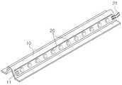
도면에 도시된 바와 같이, 본 발명의 실시예에 따른 발광다이오드 조명 기구는 방열판(10)을 포함한다.As shown in the figure, the light emitting diode lighting fixture according to the embodiment of the present invention includes a heat sink (10).
예를 들어, 방열판(10)은 도면에 도시된 바와 같이 대략 V자 형태를 가질 수 있으며, 그 하부 측면(11)에 하나 이상의 발광다이오드 소자(20)가 부착된다. 발광다이오드 소자(20)는 전원선(21)에 의해 전원을 공급받을 수 있다.For example, the
방열판(10)은 발광다이오드 소자(20)에서 발산되는 열을 효과적으로 방열할 수 있도록 열 전도성이 양호한 알루미늄과 같은 금속 재질로 형성될 수 있다.The
이때, 발광다이오드 소자(20)는 횡방향(도 1에서 X축 방향) 및 아래 방향으로 빛을 발산할 수 있도록 방열판(10)에 부착된다.At this time, the light
본 발명의 실시예에 따르면, 하나 이상의 도광판(30, 40)이 발광다이오드 소자(20)의 횡방향 인근에 배치된다.According to an embodiment of the invention, one or more
도광판(30, 40)은 발광다이오드 소자(20)에서 나온 빛을 분산 및 확산할 수 있는 종래의 광원 장치에 사용되는 이미 알려진 재질로 형성될 수 있으며, 예를 들어 아크릴 재질로 형성될 수 있다.The
도광판(30, 40)에는 발광다이오드 소자(20)에서 발산된 빛의 일부를 안내하는 복수의 도파 홈(31, 41)이 각각 형성된다.The
이하에서 도면부호 30의 도광판을 제1 도광판이라 칭하고 도면부호 40의 도 광판을 제2 도광판이라 칭한다.Hereinafter, the
한편, 본 실시예에서는 한 쌍의 제1 도광판(30)이 방열판(10)의 양측에 각각 배치되고 한 쌍의 제1 도광판(30)의 아래에 한 쌍의 제2 도광판(40)이 각각 배치되는 경우이나, 본 발명의 다른 실시예에 따르면 방열판(10)이 복수로 구비될 수 있으며 그 경우 제1 도광판(30)이 복수의 방열판(10) 사이 및 가장 외측에 있는 방열판(10)의 외측에 각각 배치될 수 있으며 제2 도광판(40)이 제1 도광판(30)의 아래에 각각 배치될 수 있다. 즉, 본 실시예에서는 방열판(10)이 1개이고 제1 도광판(30)과 제2 도광판(40)이 각각 2개인 경우이나, 방열판(10)이 2개 이상이고 제1 도광판(30)과 제2 도광판(40)이 각각 3개 이상일 수 있다.Meanwhile, in the present exemplary embodiment, a pair of
도 2 및 도 4를 참조하면, 제1 도광판(30)과 제2 도광판(40)은 상하 방향으로 서로 인접하게 배치되며, 제1 도파 홈(31)이 제1 도광판(30)의 하면(33)에 형성되고 제2 도파 홈(41)이 제2 도광판(40)의 상면(45)에 형성된다.2 and 4, the first LGP 30 and the second LGP 40 are disposed adjacent to each other in the vertical direction, and the
제1 도파 홈(31)과 제2 도파 홈(41)은 각각 복수로 형성될 수 있으며 대략 V자 형태를 가질 수 있다.The
이때, 도면에 도시된 바와 같이, 제 1 도파 홈(31)과 제2 도파 홈(41)은 횡방향(도 1에서 X축 방향)으로 연장되어 형성된다.At this time, as shown in the figure, the
이러한 제1 도파 홈(31)과 제2 도파 홈(41)으로 유입된 빛은 횡방향으로 더 멀리 전달될 수 있어서 전체적으로 발광다이오드 조명 기구가 평활성이 큰 빛을 발산하게 된다. 즉, 제1 도광판(30)과 제2 도광판(40)이 제1 도파 홈(31)과 제2 도파 홈(41)을 구비함으로써 발광다이오드 조명 기구의 빛이 평활성이 큰 빛으로 전 환되며 이에 따라 빛이 횡방향으로 더 멀리까지 전달될 수 있게 된다.The light introduced into the
반사 시트(50)가 제1 도광판(30)의 상면(35)에 부착된다. 반사 시트(50)는 제1 도광판(30)에 의해 위 방향으로 발산되는 빛을 반사하여 빛이 제1 도광판(30)의 아래 방향으로 반사되어 진행하게 한다.The
한편, 투명 확산판(60)이 발광다이오드 소자(20) 아래에 배치된다. 투명 확산판(60)은 발광다이오드 소자(20)에서 아래 방향으로 발산된 빛을 확산하여 빛이 보다 균일하게 되도록 하는 역할을 한다.Meanwhile, the
그리고 전면 커버(70)와 후면 커버(80)가 구비될 수 있다. 후면 커버(80)와 전면 커버(70)는 제1 도광판(30) 및 제2 도광판(40)의 위 아래에 각각 고정되어 제1 도광판(30)과 제2 도광판(40)을 고정하는 기능을 수행한다. 또한 도면에 도시된 바와 같이 투명 확산판(60)이 전면 커버(70)에 설치될 수 있다. 예를 들어, 전면 커버(70)와 후면 커버(80)는 금속 재질로 형성될 수 있다.The
이때, 도 1에 도시된 고정 부재(90)가 전면 커버(70)와 후면 커버(80)를 서로 고정하기 위해 사용될 수 있다. 고정 부재(90)의 상부 돌기(91)가 후면 커버(80)의 끼움 홈(81)에 삽입되고 하부 돌기(93)가 전면 커버(70)의 끼움 홈(71)에 삽입됨으로써 전면 커버(70)와 후면 커버(80)가 고정 부재(90)에 의해 서로 체결될 수 있다. 도 1에는 도시의 편의를 위해 고정 부재(90)가 분리된 상태로 도시되었다.In this case, the fixing member 90 illustrated in FIG. 1 may be used to fix the
한편, 도면에는 도시되지 않았으나, 본 발명의 실시예에 따른 발광다이오드 조명 기구는 발광다이오드 소자(20)에 전원을 공급하기 위한 전원 공급부를 포함할 수 있다. 예를 들어, 전원 공급부는 외부 전원에 전극, 그리고 외부 전원을 변환하여 발광다이오드로 인가하는 전기 회로 등을 포함할 수 있다.On the other hand, although not shown in the drawings, the LED lighting apparatus according to the embodiment of the present invention may include a power supply for supplying power to the
이하에서 첨부된 도 5를 참조하여 본 발명의 다른 실시예에 따른 발광다이오드 조명 기구에 대해 설명한다.Hereinafter, a light emitting diode lighting apparatus according to another embodiment of the present invention will be described with reference to FIG. 5.
도 5를 참조하면, 제1 도광판(130)과 제2 도광판(140)이 상하로 인접하게 배치되되, 제1 도파 홈(131)이 제1 도광판(130)의 하면(133)에 횡방향(도 1의 X축 방향)으로 형성되고, 제2 도파 홈(141)이 도2 도광판(140)의 상면(145)에 종방향(도 1의 Y축 방향)으로 형성된다. 즉, 상하로 배치되는 제1 도광판(130)과 제2 도광판(140)이 서로 수직인 방향으로 연장되어 형성되는 제1 도파 홈(131)과 제2 도파 홈(141)을 각각 구비한다.Referring to FIG. 5, the first
이와 같이 제1 도광판(130)의 제1 도파 홈(131)은 횡방향으로 형성되고 제2 도광판(140)의 제2 도파 홈(141)은 종방향으로 형성됨으로써 빛이 횡방향으로 전달됨과 동시에 아래 방향으로도 골고루 퍼져 나가게 된다.As such, the
이하에서 첨부된 도 6을 참조하여 본 발명의 또 다른 실시예에 따른 발광다이오드 조명 기구에 대해 설명한다.Hereinafter, a light emitting diode lighting apparatus according to another embodiment of the present invention will be described with reference to FIG. 6.
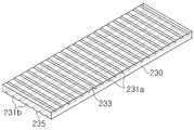
먼저, 도 6 및 도 7을 참조하면, 본 실시예에서는 상하 방향으로 두 개의 도광판이 인접하게 배열되는 것이 아니라 상하 방향으로 하나의 도광판(230)이 구비된다.First, referring to FIGS. 6 and 7, in the present exemplary embodiment, two light guide plates are disposed adjacent to each other in the vertical direction, but one
이때, 도광판(230)은 서로 직교하는 방향으로 형성되는 제1 도파 홈(231a)과 제 2 도파 홈(231b)을 구비한다. 예를 들어, 제1 도파 홈(231a)이 도광판(230)의 상면(235)에 횡방향으로 형성되고, 제2 도파 홈(231b)이 도광판(230)의 하면(233)에 종방향으로 형성된다.In this case, the
이와 같이 하나의 도광판(230)이 서로 직교하는 방향으로 연장되는 도파 홈(231a, 231b)이 모두 구비됨으로써, 하나의 도광판(230)으로도 빛이 횡방향 및 아래 방향으로 골고루 퍼져 나가도록 할 수 있다.As such, the
이상에서 본 발명의 실시예를 설명하였으나, 본 발명의 권리범위는 이에 한정되지 아니하며 본 발명의 실시예로부터 본 발명이 속하는 기술분야에서 통상의 지식을 가진 자에 의해 용이하게 변경되어 균등한 것으로 인정되는 범위의 모든 변경 및 수정을 포함한다.Although the embodiments of the present invention have been described above, the scope of the present invention is not limited thereto, and it is recognized that the present invention is easily changed and equivalent by those skilled in the art to which the present invention pertains. Includes all changes and modifications to the scope of the matter.
도 1은 본 발명의 실시예에 따른 발광다이오드 조명 기구의 사시도이다.1 is a perspective view of a light emitting diode lighting fixture according to an embodiment of the present invention.
도 2는 도 1의 Ⅱ-Ⅱ선을 따라 절개한 단면도이다.FIG. 2 is a cross-sectional view taken along the line II-II of FIG. 1.
도 3은 본 발명의 실시예에 따른 발광다이오드 조명 기구의 방열판 및 그에 부착된 발광다이오드를 보여주는 사시도이다.Figure 3 is a perspective view showing a heat sink and a light emitting diode attached thereto of the light emitting diode lighting fixture according to an embodiment of the present invention.
도 4는 본 발명의 실시예에 따른 발광다이오드 조명 기구의 제1 도광판과 제2 도광판을 보여주는 도면이다.4 is a view showing a first LGP and a second LGP of the LED lighting apparatus according to the embodiment of the present invention.
도 5는 본 발명의 다른 실시예에 따른 발광다이오드 조명 기구의 제1 도광판과 제2 도광판을 보여주는 도면이다.5 is a view illustrating a first light guide plate and a second light guide plate of a light emitting diode lighting fixture according to another embodiment of the present invention.
도 6은 본 발명의 또 다른 실시예에 다른 발광다이오드 조명 기구의 단면도이다.6 is a cross-sectional view of a light emitting diode lighting fixture according to another embodiment of the present invention.
도 7은 도 6의 발광다이오드 조명 기구의 도광판을 보여주는 도면이다.FIG. 7 is a view illustrating a light guide plate of the light emitting diode lighting fixture of FIG. 6.
Claims (6)
Translated fromKoreanPriority Applications (1)
| Application Number | Priority Date | Filing Date | Title |
|---|---|---|---|
| KR1020090091288AKR101112020B1 (en) | 2009-09-25 | 2009-09-25 | Light emitting diode illumination lamp |
Applications Claiming Priority (1)
| Application Number | Priority Date | Filing Date | Title |
|---|---|---|---|
| KR1020090091288AKR101112020B1 (en) | 2009-09-25 | 2009-09-25 | Light emitting diode illumination lamp |
Publications (2)
| Publication Number | Publication Date |
|---|---|
| KR20110033699A KR20110033699A (en) | 2011-03-31 |
| KR101112020B1true KR101112020B1 (en) | 2012-02-24 |
Family
ID=43938064
Family Applications (1)
| Application Number | Title | Priority Date | Filing Date |
|---|---|---|---|
| KR1020090091288AExpired - Fee RelatedKR101112020B1 (en) | 2009-09-25 | 2009-09-25 | Light emitting diode illumination lamp |
Country Status (1)
| Country | Link |
|---|---|
| KR (1) | KR101112020B1 (en) |
Cited By (1)
| Publication number | Priority date | Publication date | Assignee | Title |
|---|---|---|---|---|
| WO2013168949A1 (en)* | 2012-05-10 | 2013-11-14 | 엘지이노텍 주식회사 | Lighting device |
Families Citing this family (5)
| Publication number | Priority date | Publication date | Assignee | Title |
|---|---|---|---|---|
| US9081125B2 (en) | 2011-08-08 | 2015-07-14 | Quarkstar Llc | Illumination devices including multiple light emitting elements |
| EP2895794B1 (en)* | 2012-09-13 | 2018-06-27 | Quarkstar LLC | Illumination systems providing direct and indirect illumination |
| CN105723150B (en) | 2013-09-17 | 2019-02-22 | 夸克星有限责任公司 | Light guide lighting fixture with light divergence modifier |
| EP3026326A1 (en)* | 2014-11-28 | 2016-06-01 | Eral S.R.L. | Led lamp |
| IT201900025279A1 (en)* | 2019-12-23 | 2021-06-23 | Beghelli Spa | OPTICAL DEVICE FOR LED LIGHTING APPLIANCES |
Citations (3)
| Publication number | Priority date | Publication date | Assignee | Title |
|---|---|---|---|---|
| JP2002228847A (en) | 2001-02-07 | 2002-08-14 | Yuka Denshi Co Ltd | Light guide, surface light source device and liquid crystal display device using the same |
| JP2005071610A (en)* | 2003-06-26 | 2005-03-17 | Toyota Industries Corp | Light guide plate and plane light source device |
| KR20070036186A (en)* | 2004-08-06 | 2007-04-02 | 가부시키가이샤 구라레 | Light guide plate, its manufacturing method, and surface light source device provided with the same |
- 2009
- 2009-09-25KRKR1020090091288Apatent/KR101112020B1/ennot_activeExpired - Fee Related
Patent Citations (3)
| Publication number | Priority date | Publication date | Assignee | Title |
|---|---|---|---|---|
| JP2002228847A (en) | 2001-02-07 | 2002-08-14 | Yuka Denshi Co Ltd | Light guide, surface light source device and liquid crystal display device using the same |
| JP2005071610A (en)* | 2003-06-26 | 2005-03-17 | Toyota Industries Corp | Light guide plate and plane light source device |
| KR20070036186A (en)* | 2004-08-06 | 2007-04-02 | 가부시키가이샤 구라레 | Light guide plate, its manufacturing method, and surface light source device provided with the same |
Cited By (2)
| Publication number | Priority date | Publication date | Assignee | Title |
|---|---|---|---|---|
| WO2013168949A1 (en)* | 2012-05-10 | 2013-11-14 | 엘지이노텍 주식회사 | Lighting device |
| US10001596B2 (en) | 2012-05-10 | 2018-06-19 | Lg Innotek Co., Ltd. | Lighting device |
Also Published As
| Publication number | Publication date |
|---|---|
| KR20110033699A (en) | 2011-03-31 |
Similar Documents
| Publication | Publication Date | Title |
|---|---|---|
| KR101191213B1 (en) | Lighting apparatus | |
| TWI390159B (en) | Lighting device | |
| JP6062180B2 (en) | Lighting device | |
| KR101112020B1 (en) | Light emitting diode illumination lamp | |
| JP2007234385A (en) | Backlight device | |
| KR101475047B1 (en) | Back Light Unit | |
| KR20100138836A (en) | Lighting equipment | |
| JP2015535654A (en) | Luminous arrangement using light guide | |
| WO2014021456A1 (en) | Illumination device | |
| KR101139655B1 (en) | Frame of LED Fluorescent Lamp | |
| JP5133439B2 (en) | Lighting device and lighting device including the same | |
| TWI408458B (en) | Sidelight type backlight module | |
| US9435931B2 (en) | LED lighting apparatus | |
| JP4841513B2 (en) | Lighting device | |
| JP2012226964A (en) | Illumination apparatus and illumination equipment equipped with the same | |
| KR20140069823A (en) | Lighting apparatus | |
| CN202691628U (en) | Lamp fitting | |
| KR20120128484A (en) | Surface lighting device | |
| CN101988659A (en) | Side light type backlight module | |
| JP6113430B2 (en) | Lighting device | |
| KR101761873B1 (en) | Flat type LED lamp assembly | |
| JP2013218965A (en) | Lighting fixture | |
| KR102115347B1 (en) | Apparatus for lighting | |
| JP7357214B2 (en) | lighting equipment | |
| KR101252689B1 (en) | LED lamp |
Legal Events
| Date | Code | Title | Description |
|---|---|---|---|
| A201 | Request for examination | ||
| PA0109 | Patent application | St.27 status event code:A-0-1-A10-A12-nap-PA0109 | |
| PA0201 | Request for examination | St.27 status event code:A-1-2-D10-D11-exm-PA0201 | |
| P11-X000 | Amendment of application requested | St.27 status event code:A-2-2-P10-P11-nap-X000 | |
| P13-X000 | Application amended | St.27 status event code:A-2-2-P10-P13-nap-X000 | |
| D13-X000 | Search requested | St.27 status event code:A-1-2-D10-D13-srh-X000 | |
| D14-X000 | Search report completed | St.27 status event code:A-1-2-D10-D14-srh-X000 | |
| R18-X000 | Changes to party contact information recorded | St.27 status event code:A-3-3-R10-R18-oth-X000 | |
| PG1501 | Laying open of application | St.27 status event code:A-1-1-Q10-Q12-nap-PG1501 | |
| E902 | Notification of reason for refusal | ||
| PE0902 | Notice of grounds for rejection | St.27 status event code:A-1-2-D10-D21-exm-PE0902 | |
| T11-X000 | Administrative time limit extension requested | St.27 status event code:U-3-3-T10-T11-oth-X000 | |
| E13-X000 | Pre-grant limitation requested | St.27 status event code:A-2-3-E10-E13-lim-X000 | |
| P11-X000 | Amendment of application requested | St.27 status event code:A-2-2-P10-P11-nap-X000 | |
| P13-X000 | Application amended | St.27 status event code:A-2-2-P10-P13-nap-X000 | |
| R18-X000 | Changes to party contact information recorded | St.27 status event code:A-3-3-R10-R18-oth-X000 | |
| E701 | Decision to grant or registration of patent right | ||
| PE0701 | Decision of registration | St.27 status event code:A-1-2-D10-D22-exm-PE0701 | |
| GRNT | Written decision to grant | ||
| PR0701 | Registration of establishment | St.27 status event code:A-2-4-F10-F11-exm-PR0701 | |
| PR1002 | Payment of registration fee | Fee payment year number:1 St.27 status event code:A-2-2-U10-U11-oth-PR1002 | |
| PG1601 | Publication of registration | St.27 status event code:A-4-4-Q10-Q13-nap-PG1601 | |
| FPAY | Annual fee payment | Payment date:20150528 Year of fee payment:4 | |
| PR1001 | Payment of annual fee | Fee payment year number:4 St.27 status event code:A-4-4-U10-U11-oth-PR1001 | |
| FPAY | Annual fee payment | Payment date:20151112 Year of fee payment:5 | |
| PR1001 | Payment of annual fee | Fee payment year number:5 St.27 status event code:A-4-4-U10-U11-oth-PR1001 | |
| P22-X000 | Classification modified | St.27 status event code:A-4-4-P10-P22-nap-X000 | |
| P22-X000 | Classification modified | St.27 status event code:A-4-4-P10-P22-nap-X000 | |
| PN2301 | Change of applicant | St.27 status event code:A-5-5-R10-R11-asn-PN2301 St.27 status event code:A-5-5-R10-R13-asn-PN2301 | |
| LAPS | Lapse due to unpaid annual fee | ||
| PC1903 | Unpaid annual fee | Not in force date:20170128 Payment event data comment text:Termination Category : DEFAULT_OF_REGISTRATION_FEE St.27 status event code:A-4-4-U10-U13-oth-PC1903 | |
| PC1903 | Unpaid annual fee | Ip right cessation event data comment text:Termination Category : DEFAULT_OF_REGISTRATION_FEE Not in force date:20170128 St.27 status event code:N-4-6-H10-H13-oth-PC1903 | |
| P22-X000 | Classification modified | St.27 status event code:A-4-4-P10-P22-nap-X000 | |
| P22-X000 | Classification modified | St.27 status event code:A-4-4-P10-P22-nap-X000 | |
| R18-X000 | Changes to party contact information recorded | St.27 status event code:A-5-5-R10-R18-oth-X000 | |
| R18-X000 | Changes to party contact information recorded | St.27 status event code:A-5-5-R10-R18-oth-X000 | |
| R18-X000 | Changes to party contact information recorded | St.27 status event code:A-5-5-R10-R18-oth-X000 |