KR101106308B1 - Battery pack - Google Patents
Battery packDownload PDFInfo
- Publication number
- KR101106308B1 KR101106308B1KR1020100052330AKR20100052330AKR101106308B1KR 101106308 B1KR101106308 B1KR 101106308B1KR 1020100052330 AKR1020100052330 AKR 1020100052330AKR 20100052330 AKR20100052330 AKR 20100052330AKR 101106308 B1KR101106308 B1KR 101106308B1
- Authority
- KR
- South Korea
- Prior art keywords
- plate
- hole
- cooling water
- coolant
- layer
- Prior art date
- Legal status (The legal status is an assumption and is not a legal conclusion. Google has not performed a legal analysis and makes no representation as to the accuracy of the status listed.)
- Active
Links
- 239000002826coolantSubstances0.000claimsabstractdescription135
- 239000000498cooling waterSubstances0.000claimsabstractdescription95
- 238000001816coolingMethods0.000claimsabstractdescription41
- 229910052751metalInorganic materials0.000claimsdescription8
- 239000002184metalSubstances0.000claimsdescription8
- 230000010349pulsationEffects0.000claimsdescription8
- 230000002265preventionEffects0.000claimsdescription6
- 239000013585weight reducing agentSubstances0.000claimsdescription5
- 239000000463materialSubstances0.000claimsdescription4
- 239000007769metal materialSubstances0.000claimsdescription4
- 239000011810insulating materialSubstances0.000claimsdescription3
- 239000004020conductorSubstances0.000claimsdescription2
- 238000000034methodMethods0.000claims16
- 239000010410layerSubstances0.000description55
- 230000008878couplingEffects0.000description18
- 238000010168coupling processMethods0.000description18
- 238000005859coupling reactionMethods0.000description18
- 239000007788liquidSubstances0.000description4
- 230000017525heat dissipationEffects0.000description3
- 239000007791liquid phaseSubstances0.000description3
- 229910052782aluminiumInorganic materials0.000description2
- XAGFODPZIPBFFR-UHFFFAOYSA-NaluminiumChemical compound[Al]XAGFODPZIPBFFR-UHFFFAOYSA-N0.000description2
- 230000006866deteriorationEffects0.000description2
- 238000010586diagramMethods0.000description2
- 238000007599dischargingMethods0.000description2
- 238000004519manufacturing processMethods0.000description2
- 239000007789gasSubstances0.000description1
- 239000007792gaseous phaseSubstances0.000description1
- 239000000203mixtureSubstances0.000description1
- 238000012986modificationMethods0.000description1
- 230000004048modificationEffects0.000description1
- 239000012071phaseSubstances0.000description1
- 239000002356single layerSubstances0.000description1
Images


Classifications
- H—ELECTRICITY
- H01—ELECTRIC ELEMENTS
- H01M—PROCESSES OR MEANS, e.g. BATTERIES, FOR THE DIRECT CONVERSION OF CHEMICAL ENERGY INTO ELECTRICAL ENERGY
- H01M10/00—Secondary cells; Manufacture thereof
- H01M10/42—Methods or arrangements for servicing or maintenance of secondary cells or secondary half-cells
- H01M10/4207—Methods or arrangements for servicing or maintenance of secondary cells or secondary half-cells for several batteries or cells simultaneously or sequentially
- H—ELECTRICITY
- H01—ELECTRIC ELEMENTS
- H01M—PROCESSES OR MEANS, e.g. BATTERIES, FOR THE DIRECT CONVERSION OF CHEMICAL ENERGY INTO ELECTRICAL ENERGY
- H01M10/00—Secondary cells; Manufacture thereof
- H01M10/60—Heating or cooling; Temperature control
- H01M10/61—Types of temperature control
- H01M10/613—Cooling or keeping cold
- H—ELECTRICITY
- H01—ELECTRIC ELEMENTS
- H01M—PROCESSES OR MEANS, e.g. BATTERIES, FOR THE DIRECT CONVERSION OF CHEMICAL ENERGY INTO ELECTRICAL ENERGY
- H01M10/00—Secondary cells; Manufacture thereof
- H01M10/60—Heating or cooling; Temperature control
- H01M10/62—Heating or cooling; Temperature control specially adapted for specific applications
- H01M10/625—Vehicles
- H—ELECTRICITY
- H01—ELECTRIC ELEMENTS
- H01M—PROCESSES OR MEANS, e.g. BATTERIES, FOR THE DIRECT CONVERSION OF CHEMICAL ENERGY INTO ELECTRICAL ENERGY
- H01M10/00—Secondary cells; Manufacture thereof
- H01M10/60—Heating or cooling; Temperature control
- H01M10/64—Heating or cooling; Temperature control characterised by the shape of the cells
- H01M10/647—Prismatic or flat cells, e.g. pouch cells
- H—ELECTRICITY
- H01—ELECTRIC ELEMENTS
- H01M—PROCESSES OR MEANS, e.g. BATTERIES, FOR THE DIRECT CONVERSION OF CHEMICAL ENERGY INTO ELECTRICAL ENERGY
- H01M10/00—Secondary cells; Manufacture thereof
- H01M10/60—Heating or cooling; Temperature control
- H01M10/65—Means for temperature control structurally associated with the cells
- H01M10/655—Solid structures for heat exchange or heat conduction
- H01M10/6556—Solid parts with flow channel passages or pipes for heat exchange
- H—ELECTRICITY
- H01—ELECTRIC ELEMENTS
- H01M—PROCESSES OR MEANS, e.g. BATTERIES, FOR THE DIRECT CONVERSION OF CHEMICAL ENERGY INTO ELECTRICAL ENERGY
- H01M10/00—Secondary cells; Manufacture thereof
- H01M10/60—Heating or cooling; Temperature control
- H01M10/65—Means for temperature control structurally associated with the cells
- H01M10/656—Means for temperature control structurally associated with the cells characterised by the type of heat-exchange fluid
- H01M10/6567—Liquids
- H—ELECTRICITY
- H01—ELECTRIC ELEMENTS
- H01M—PROCESSES OR MEANS, e.g. BATTERIES, FOR THE DIRECT CONVERSION OF CHEMICAL ENERGY INTO ELECTRICAL ENERGY
- H01M50/00—Constructional details or processes of manufacture of the non-active parts of electrochemical cells other than fuel cells, e.g. hybrid cells
- H01M50/20—Mountings; Secondary casings or frames; Racks, modules or packs; Suspension devices; Shock absorbers; Transport or carrying devices; Holders
- H01M50/204—Racks, modules or packs for multiple batteries or multiple cells
- H01M50/207—Racks, modules or packs for multiple batteries or multiple cells characterised by their shape
- H01M50/209—Racks, modules or packs for multiple batteries or multiple cells characterised by their shape adapted for prismatic or rectangular cells
- Y—GENERAL TAGGING OF NEW TECHNOLOGICAL DEVELOPMENTS; GENERAL TAGGING OF CROSS-SECTIONAL TECHNOLOGIES SPANNING OVER SEVERAL SECTIONS OF THE IPC; TECHNICAL SUBJECTS COVERED BY FORMER USPC CROSS-REFERENCE ART COLLECTIONS [XRACs] AND DIGESTS
- Y02—TECHNOLOGIES OR APPLICATIONS FOR MITIGATION OR ADAPTATION AGAINST CLIMATE CHANGE
- Y02E—REDUCTION OF GREENHOUSE GAS [GHG] EMISSIONS, RELATED TO ENERGY GENERATION, TRANSMISSION OR DISTRIBUTION
- Y02E60/00—Enabling technologies; Technologies with a potential or indirect contribution to GHG emissions mitigation
- Y02E60/10—Energy storage using batteries
Landscapes
- Chemical & Material Sciences (AREA)
- Chemical Kinetics & Catalysis (AREA)
- Electrochemistry (AREA)
- General Chemical & Material Sciences (AREA)
- Engineering & Computer Science (AREA)
- Manufacturing & Machinery (AREA)
- Secondary Cells (AREA)
- Battery Mounting, Suspending (AREA)
Abstract
Translated fromKoreanDescription
Translated fromKorean본 발명은 배터리 팩에 관한 것이다.The present invention relates to a battery pack.
일반적으로 이차전지는 충전 및 방전이 가능하여 반복적으로 사용할 수 있는 전지로, 하나의 배터리 셀로 이루어져 휴대폰, 노트북, 컴퓨터, 카메라, 캠코더 등의 휴대용 소형 전자기기에 사용되거나, 다수의 배터리 셀을 포함하는 배터리 팩으로 이루어져 고출력의 하이브리드 전기 자동차(HEV), 전기 자동차(EV) 등의 모터 구동용 전원으로 사용될 수 있다.In general, a secondary battery is a battery that can be repeatedly used because it can be charged and discharged, and is used in portable small electronic devices such as mobile phones, laptops, computers, cameras, camcorders, etc., or includes a plurality of battery cells. The battery pack may be used as a power source for driving a motor such as a high power hybrid electric vehicle (HEV) and an electric vehicle (EV).
상기 배터리 팩은 고출력의 모터 구동용 전원에 사용되어, 충전 또는 방전 동작에 의해 많은 열을 발생시킨다. 이러한 열은 배터리 셀을 열화 시킬 수 있다. 이에 따라, 방열 특성을 향상시키는 구조의 배터리 팩이 요구되고 있다.The battery pack is used for a high power motor driving power source, and generates a lot of heat by a charging or discharging operation. This heat can degrade the battery cells. Accordingly, there is a demand for a battery pack having a structure for improving heat dissipation characteristics.
본 발명의 목적은 냉각수를 이용한 열교환 효율을 높여 배터리 셀로부터 발생된 열을 효율적으로 방출할 수 있고, 냉각수의 자연적인 흐름을 가능하게 하여 냉각수의 흐름을 위한 별도의 구동 장치를 필요로 하지 않는 배터리 팩에 관한 것이다.An object of the present invention is to increase the heat exchange efficiency using the coolant to efficiently discharge the heat generated from the battery cell, and to enable the natural flow of the coolant does not require a separate drive device for the flow of the coolant It's about the pack.
상기 목적을 달성하기 위하여, 본 발명의 실시예에 따른 배터리 팩은 복수의 배터리 셀; 및 상기 복수의 배터리 셀에 결합된 냉각부를 포함하며, 상기 냉각부는 상기 복수의 배터리 셀에 순차적으로 배치된 제 1 플레이트, 제 2 플레이트 및 제 3 플레이트를 포함하며, 상기 제 1 플레이트에 냉각수 인입홀과 냉각수 배출홀이 형성되고 상기 제 2 플레이트에 냉각수 흐름 경로가 형성된 복수의 냉각 플레이트; 및 상기 제 1 플레이트로 냉각수를 공급하고 상기 제 1 플레이트로부터 냉각수를 회수하는 냉각수 저장부를 포함하는 것을 특징으로 한다.In order to achieve the above object, a battery pack according to an embodiment of the present invention comprises a plurality of battery cells; And a cooling unit coupled to the plurality of battery cells, wherein the cooling unit includes a first plate, a second plate, and a third plate sequentially disposed in the plurality of battery cells, and a coolant inlet hole in the first plate. A plurality of cooling plates formed with a cooling water discharge hole and a cooling water flow path formed in the second plate; And a cooling water storage unit supplying cooling water to the first plate and recovering the cooling water from the first plate.
상기 냉각수 흐름 경로는 상기 제 1 플레이트와 상기 제 2 플레이트 사이에서 상기 제 2 플레이트에 형성된 복수의 홀들에 의해 형성될 수 있다.The coolant flow path may be formed by a plurality of holes formed in the second plate between the first plate and the second plate.
상기 복수의 배터리 셀과 상기 제 1 플레이트 사이에 써멀 패드가 개재될 수 있다.A thermal pad may be interposed between the plurality of battery cells and the first plate.
상기 제 1 플레이트와 상기 제 3 플레이트는 열전도성 재질로 형성될 수 있다. 예를 들어, 상기 제 1 플레이트와 상기 제 3 플레이트는 금속 재질로 형성될 수 있다.The first plate and the third plate may be formed of a thermally conductive material. For example, the first plate and the third plate may be formed of a metal material.
상기 냉각부는 상기 제 1 플레이트의 일측에 상기 냉각수 인입홀과 연결되는 제 1 연결홀과, 상기 냉각수 배출홀과 연결되는 제 2 연결홀을 갖는 연결부를 더 포함하며, 상기 냉각수 저장부는 상기 제 1 연결홀과 연결되는 제 1 연결관과, 상기 제 2 연결홀과 연결되는 제 2 연결관을 더 포함할 수 있다.The cooling unit further includes a connection unit having a first connection hole connected to the coolant inlet hole at one side of the first plate, and a second connection hole connected to the coolant discharge hole, and the coolant storage unit is connected to the first connection hole. The display device may further include a first connecting pipe connected to the hole and a second connecting pipe connected to the second connecting hole.
상기 제 2 플레이트의 냉각수 흐름 경로에 위크가 형성될 수 있다. 예를 들어, 상기 위크는 제 1 금속 라인과 제 2 금속 라인이 메쉬 형태로 형성되어 이루어질 수 있다.A wick may be formed in the coolant flow path of the second plate. For example, the wick may be formed by forming a first metal line and a second metal line in a mesh form.
상기 제 2 플레이트는 단열성 재질로 형성될 수 있다. 예를 들어, 상기 제 2 플레이트는 플라스틱 재질로 형성될 수 있다.The second plate may be formed of a heat insulating material. For example, the second plate may be formed of a plastic material.
상기 제 2 플레이트는 상기 제 1 플레이트와 접촉하는 제 1 층; 상기 제 1 층과 접촉하는 제 2 층; 및 상기 제 2 층과 상기 제 3 플레이트 사이에 개재되는 제 3 층을 포함할 수 있다.The second plate includes a first layer in contact with the first plate; A second layer in contact with the first layer; And a third layer interposed between the second layer and the third plate.
상기 제 1 층은 상기 제 1 플레이트로부터 상기 냉각수가 인입되는 제 1 냉각수 인입홀; 상기 제 1 층에서 상기 냉각수가 퍼지도록 형성되는 제 1 냉각수 전달홀; 상기 제 1 층에서 상기 냉각수가 수집되도록 형성되는 제 1 냉각수 수집홀; 및 상기 냉각수가 상기 제 1 플레이트로 배출되도록 하는 제 1 냉각수 배출홀을 포함할 수 있다.The first layer may include a first coolant inlet hole through which the coolant is introduced from the first plate; A first cooling water transfer hole formed to spread the cooling water in the first layer; A first cooling water collection hole formed to collect the cooling water in the first layer; And a first cooling water discharge hole through which the cooling water is discharged to the first plate.
상기 제 2 층은 상기 제 1 냉각수 인입홀과 연결되는 제 2 냉각수 인입홀; 상기 제 1 냉각수 전달홀의 일측과 연결되는 제 2 냉각수 배출홀; 상기 제 1 냉각수 전달홀의 타측과 연결되는 제 2 냉각수 전달홀; 및 상기 제 1 냉각수 수집홀과 연결되는 제 2 냉각수 수집홀을 포함할 수 있다.The second layer may include a second coolant inlet hole connected to the first coolant inlet hole; A second cooling water discharge hole connected to one side of the first cooling water transfer hole; A second cooling water transfer hole connected to the other side of the first cooling water transfer hole; And a second cooling water collection hole connected to the first cooling water collection hole.
상기 제 3 층은 상기 제 2 냉각수 인입홀과 연결되는 제 3 냉각수 인입홀; 상기 제 2 냉각수 배출홀과 연결되는 제 3 냉각수 배출홀; 상기 제 2 냉각수 전달홀과 연결되는 제 3 냉각수 전달홀; 및 상기 제 2 냉각수 수집홀과 연결되는 제 3 냉각수 수집홀을 포함할 수 있다. 또한, 상기 제 3 층은 맥동류 방지용 홀 또는 중량 감소용 홀을 포함할 수 있다.The third layer may include a third coolant inlet hole connected to the second coolant inlet hole; A third cooling water discharge hole connected to the second cooling water discharge hole; A third cooling water transfer hole connected to the second cooling water transfer hole; And a third cooling water collection hole connected to the second cooling water collection hole. In addition, the third layer may include a pulsation flow prevention hole or a weight reduction hole.
상기 제 2 플레이트 및 상기 제 3 플레이트 중 적어도 어느 하나는 맥동류 방지용 홀 또는 중량 감소용 홀을 포함할 수 있다.At least one of the second plate and the third plate may include a pulsation preventing hole or a weight reducing hole.
상기 복수의 냉각 플레이트는 상기 복수의 배터리 셀의 하면에 배치될 수 있다.The plurality of cooling plates may be disposed on lower surfaces of the plurality of battery cells.
또한, 본 발명의 실시예에 따른 배터리 팩은 상기 제 3 플레이트를 노출시키면서 상기 복수의 배터리 셀과 상기 냉각부를 커버하는 하우징 케이스를 더 포함할 수 있다. 여기서, 상기 제 3 플레이트에 히트 싱크가 더 설치될 수 있다.In addition, the battery pack according to an embodiment of the present invention may further include a housing case covering the plurality of battery cells and the cooling unit while exposing the third plate. Here, the heat sink may be further installed on the third plate.
본 발명의 실시예에 따른 배터리 팩은 냉각수 흐름 경로를 포함하는 복수의 냉각 플레이트를 포함함으로써, 냉각수를 이용한 열교환 효율을 높일 수 있다. 따라서, 본 발명의 실시예에 따른 배터리 팩은 배터리 셀의 열을 효율적으로 방출함으로써, 열에 의한 배터리 셀의 열화를 방지할 수 있다.The battery pack according to the embodiment of the present invention may include a plurality of cooling plates including a cooling water flow path, thereby increasing heat exchange efficiency using the cooling water. Therefore, the battery pack according to the embodiment of the present invention can effectively discharge the heat of the battery cell, it is possible to prevent deterioration of the battery cell by the heat.
또한, 본 발명의 실시예에 따른 배터리 팩은 복수의 냉각 플레이트에 위크(wick)를 형성함으로써, 냉각수의 자연적인 흐름을 가능하게 할 수 있다. 따라서, 본 발명의 실시예에 따른 배터리 팩은 냉각수의 흐름을 위한 별도의 구동 장치를 필요로 하지 않아 제조 비용을 줄일 수 있다.In addition, the battery pack according to the embodiment of the present invention may enable a natural flow of the cooling water by forming wicks in the plurality of cooling plates. Therefore, the battery pack according to the embodiment of the present invention does not require a separate driving device for the flow of the cooling water can reduce the manufacturing cost.
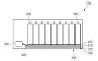
도 1은 본 발명의 일 실시예에 따른 배터리 팩을 개략적으로 도시한 개략 구성도이다.
도 2는 도 1에서 하우징 케이스를 제외한 배터리 팩을 도시한 사시도이다.
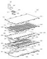
도 3은 도 1의 냉각부의 일부를 도시한 분해 사시도이다.
도 4는 도 3에 도시된 제 1 층의 일부를 도시한 단면도이다.
도 5는 도 1의 냉각부에 형성된 냉각수 흐름 경로를 개략적으로 보여주기 위한 도면이다.1 is a schematic diagram illustrating a battery pack according to an embodiment of the present invention.
2 is a perspective view illustrating a battery pack excluding the housing case of FIG. 1.
3 is an exploded perspective view illustrating a part of the cooling unit of FIG. 1.
4 is a cross-sectional view of a portion of the first layer illustrated in FIG. 3.
5 is a view for schematically showing a coolant flow path formed in the cooling unit of FIG.
이하 도면을 참조하면서 본 발명의 실시예를 통해 본 발명을 보다 상세히 설명하기로 한다.DETAILED DESCRIPTION OF THE PREFERRED EMBODIMENTS The present invention will be described in more detail with reference to the accompanying drawings.
도 1은 본 발명의 일 실시예에 따른 배터리 팩을 개략적으로 도시한 개략 구성도이고, 도 2는 도 1에서 하우징 케이스를 제외한 배터리 팩을 도시한 사시도이고, 도 3은 도 1의 냉각부의 일부를 도시한 분해 사시도이고, 도 4는 도 3에 도시된 제 1 층의 일부를 도시한 단면도이다.1 is a schematic configuration diagram schematically illustrating a battery pack according to an embodiment of the present invention, FIG. 2 is a perspective view illustrating a battery pack excluding a housing case in FIG. 1, and FIG. 3 is a part of the cooling unit of FIG. 1. 4 is an exploded perspective view illustrating a portion of the first layer illustrated in FIG. 3.
도 1 및 도 2를 참조하면, 본 발명의 일 실시예에 따른 배터리 팩(100)은 복수의 배터리 셀(200), 냉각부(300) 및 하우징 케이스(400)를 포함한다.1 and 2, a
상기 복수의 배터리 셀(200)은 일렬로 배치되며, 연결 부재(미도시)에 의해 패 서로 직렬 또는 병렬로 연결된다. 이러한 복수의 배터리 셀(200)은 외부 전자 기기에 연결되어 전원을 공급하는 방전 동작을 수행하거나, 외부 전자 기기로부터 전원을 공급받는 충전 동작을 수행한다.The plurality of
상기 복수의 배터리 셀(200) 각각은 양극판과 음극판이 세퍼레이터를 사이에 두고 위치하는 전극 조립체(211)와, 전극 조립체(211)가 내장되는 공간을 구비하는 케이스(212)와, 케이스(212)와 결합되어 케이스(212)를 밀폐하는 캡 조립체(213), 및 양극판과 음극판과 각각 전기적으로 연결되고 캡 조립체(213)의 외측으로 돌출되는 양극 단자(214)와 음극단자(215)를 포함한다. 여기서, 상기 복수의 배터리 셀(200)은 방전 동작 또는 충전 동작 등을 수행하는 과정에 원하지 않게 많은 열을 발생시킬 수 있다.
Each of the plurality of
상기 냉각부(300)는 복수의 배터리 셀(200)에 결합되며, 냉각수에 의해 복수의 배터리 셀(200)을 냉각시키는 역할을 한다. 이를 위해, 상기 냉각부(300)는 복수의 냉각 플레이트(310, 320, 330), 연결부(370) 및 냉각수 저장부(380)를 포함한다. 여기서, 상기 냉각부(300)는 진공 상태일 수 있다.The
상기 복수의 냉각 플레이트(310, 320, 330)는 복수의 배터리 셀(200)의 하면에 배치되며, 복수의 배터리 셀(200)을 냉각시키기 위한 냉각수의 냉각수 흐름 경로를 포함한다. 상기 복수의 냉각 플레이트(310, 320, 330)는 복수의 배터리 셀(200)에 가까운 순서로 배치되는 제 1 플레이트(310), 제 2 플레이트(320) 및 제 3 플레이트(330)로 구분될 수 있다.The plurality of
상기 제 1 플레이트(310)는 복수의 배터리 셀(200)에 가장 가깝게 접촉하며, 복수의 냉각 플레이트(310, 320, 330)에서 내부층을 이룬다. 이러한 제 1 플레이트(310)는 복수의 배터리 셀(200)로부터 발생된 열을 제 2 플레이트(320)로 전달하는 역할을 한다. 이를 위해, 상기 제 1 플레이트(310)는 열전도성을 갖는 알루미늄과 같은 금속 재질로 형성되며, 대략 복수의 배터리 셀(200)과 전면적으로 접촉되는 면적을 가진다. 여기서, 상기 제 1 플레이트(310)는 외주연의 일부에서 돌출된 돌출 영역을 가지며, 이러한 돌출 영역에는 냉각수 인입홀(311), 냉각수 배출홀(312) 및 내측 결합홀(313)이 형성된다.The
상기 냉각수 인입홀(311)은 냉각수가 복수의 냉각 플레이트(310, 320, 330)로 처음 인입되도록 하며, 냉각수 배출홀(312)은 냉각수가 복수의 냉각 플레이트(310, 320, 330)로부터 마지막으로 배출되도록 하고, 내측 결합홀(313)은 제 1 플레이트(310), 제 2 플레이트(320), 제 3 플레이트(330)를 결합시키는 결합 부재가 통과하도록 한다. 한편, 상기 복수의 배터리 셀(200)과 제 1 플레이트(310) 사이에는 복수의 배터리 셀(200)의 열방출 효율을 높이기 위해 써멀 패드(thermal pad)가 개재될 수 있다.
The
상기 제 2 플레이트(320)는 제 1 플레이트(310)와 접촉하며, 복수의 냉각 플레이트(310, 320, 330)에서 중간층을 이룬다. 상기 제 2 플레이트(320)는 실질적으로 냉각수 흐름 경로를 포함하며, 제 1 플레이트(310)와 제 3 플레이트(330) 사이에서 냉각수 흐름 경로의 형성을 위한 다수의 홀들을 포함한다. 이러한 제 2 플레이트(320)는 냉각수 흐름 경로를 통해 흐르는 냉각수가 복수의 배터리 셀(200)과 열교환 하여 복수의 배터리 셀(200)을 냉각시키는 공간을 제공한다. 상기 열교환을 수행한 냉각수는 액상 및 기상이 혼재된 상태이거나, 기상 상태일 수 있다. 여기서, 상기 냉각수 흐름 경로의 일부에는 금속 메쉬와 같은 위크(wick)가 형성된다. 상기 위크는 냉각수 흐름의 구동력인 모세관력을 발생시켜 냉각수의 자연적인 흐름을 가능하게 한다.The
또한, 상기 제 2 플레이트(320)는 복수의 배터리 셀(200)의 열용량에 따라 냉각수의 흐름이 조절되도록, 단열성 재질, 예를 들어 플라스틱 재질로 형성될 수 있다. 이러한 제 2 플레이트(320)는 제 1 플레이트(310)를 통해 전달된 복수의 배터리 셀(200)의 열이 높으면 냉각수의 흐름을 빠르게 하며, 제 1 플레이트(310)를 통해 전달된 복수의 배터리 셀(200)의 열이 낮으면 냉각수의 흐름을 느리게 한다. 여기서, 상기 제 2 플레이트(320)가 열전도성을 갖는 재질로 형성되면, 제 1 플레이트(310)를 통해 전달된 복수의 배터리 셀(200)의 열이 균일해져 냉각수의 흐름을 조절할 수 없다.In addition, the
또한, 상기 제 2 플레이트(320)는 멀티층으로 구성될 수 있으며, 예를 들어 제 1 층(340), 제 2 층(350) 및 제 3 층(360)을 포함할 수 있다. 여기서, 상기 제 2 플레이트(320)는 단일층으로 구성될 수도 있으므로, 본 발명에서 제 2 플레이트(320)의 구성을 한정하는 것은 아니다.In addition, the
상기 제 1 층(340)은 제 1 플레이트(310)와 접촉하며 대략 제 1 플레이트(310)와 대응되는 면적을 가진다. 상기 제 1 층(340)은 제 1 냉각수 인입홀(341), 제 1 냉각수 전달홀(342), 제 1 냉각수 수집홀(343), 제 1 냉각수 배출홀(344) 및 제 1 결합홀(345)을 포함한다.The
상기 제 1 냉각수 인입홀(341)은 냉각수 인입홀(311)과 연결되게 형성되며, 제 1 플레이트(310)로부터 냉각수가 인입되도록 한다. 여기서, 상기 제 1 냉각수 인입홀(341)은 복수개의 홀을 가지는 형태로 형성될 수 있다. 상기 제 1 냉각수 전달홀(342)은 제 1 층(340)에서 냉각수가 퍼지도록 형성된다. 상기 제 1 냉각수 수집홀(343)은 제 1 층(340)에서 냉각수가 수집되도록 한다. 상기 제 1 냉각수 배출홀(344)은 냉각수 배출홀(312)과 연결되게 형성되며, 제 1 플레이트(310)로 냉각수가 배출되도록 한다. 상기 제 1 결합홀(345)은 제 1 플레이트(310)의 내측 결합홀(313)과 연결되게 형성되어, 제 1 플레이트(310), 제 2 플레이트(320), 제 3 플레이트(330)를 결합시키는 결합 부재(301)가 통과하도록 한다.The first
상기와 같은 제 1 층(340)은 제 1 플레이트(310)와 가장 가깝게 접촉하여 제 1 플레이트(310)를 통해 전달된 복수의 배터리 셀(200)을 냉각시키는데 메인 역할을 한다. 이에 따라, 제 1 층(340)에서 복수의 배터리 셀(200)를 냉각시키는데 사용되는 냉각수의 흐름이 용이하도록, 제 1 층(340)의 냉각수 흐름 경로를 형성하는 제 1 냉각수 인입홀(341), 제 1 냉각수 전달홀(342), 제 1 냉각수 수집홀(343), 제 1 냉각수 배출홀(344)에 위크(348)가 형성된다. 도 4는 예를 들어 제 1 냉각수 전달홀(342)에 금속 메쉬 형태의 위크(348)가 형성되는 것을 도시하였다. 상기 위크(348)는 구체적으로 제 1 금속 라인(348a)과 제 2 금속 라인(348b)이 메쉬 형태로 형성되어 이루어질 수 있다.The
상기 제 2 층(350)은 제 1 층(340)과 접촉하며, 대략 제 1 층(340)과 대응되는 면적을 가진다. 상기 제 2 층(350)은 제 2 냉각수 인입홀(351), 제 2 냉각수 배출홀(352), 제 2 냉각수 전달홀(353), 제 2 냉각수 수집홀(354) 및 제 2 결합홀(355)을 포함한다.The
상기 제 2 냉각수 인입홀(351)은 제 1 냉각수 인입홀(341)과 연결되게 형성되며, 제 1 층(340)으로부터 냉각수가 인입되도록 한다. 여기서, 상기 제 2 냉각수 인입홀(351)도 제 1 냉각수 인입홀(341)과 마찬가지로 복수개의 홀을 가지는 형태로 형성될 수 있다. 상기 제 2 냉각수 배출홀(352)은 제 1 냉각수 전달홀(342)의 일측과 연결되어, 제 2 층(350)으로부터 냉각수가 제 1 층(340)으로 인입되도록 한다. 상기 제 2 냉각수 전달홀(353)은 제 1 냉각수 전달홀(342)의 타측과 연결되어, 제 1 층(340)으로부터 냉각수가 제 2 층(350)으로 인입되도록 한다. 상기 제 2 냉각수 수집홀(354)은 제 1 냉각수 수집홀(343)과 연결되어, 제 2 층(350)으로부터 냉각수가 제 1 층(340)으로 인입되도록 한다. 상기 제 2 결합홀(355)은 제 1 층(340)의 제 1 결합홀(345)과 연결되게 형성되어, 제 1 플레이트(310), 제 2 플레이트(320), 제 3 플레이트(330)를 결합시키는 결합 부재(301)가 통과하도록 한다.The second
상기 제 3 층(360)은 제 2 층(350)과 접촉하며 대략 제 2 층(350)과 대응되는 면적을 가진다. 상기 제 3 층(360)은 제 3 냉각수 인입홀(361),제 3 냉각수 전달홀(362), 제 3 냉각수 수집홀(363) 및 제 3 결합홀(364)을 포함한다.The
상기 제 3 냉각수 인입홀(361)은 제 2 냉각수 인입홀(351)과 연결되게 형성되며, 제 2 층(350)으로부터 냉각수가 인입되도록 한다. 여기서, 제 3 냉각수 인입홀(361)은 제 2 냉각수 인입홀(351)과 마찬가지로 복수개의 홀을 가지는 형태로 형성될 수 있으며, 복수개의 홀은 수평 방향으로 연장되어 복수개의 트랙(361a, 361b, 361c)을 형성할 수 있다. 이러한 제 3 냉각수 인입홀(361)은 제 2 층(350)으로부터 인입되는 냉각수를 제 3 층(360)에서 분배하여 흐르도록 한다. 상기 제 3 냉각수 전달홀(362)은 제 2 냉각수 전달홀(353)과 연결된다. 상기 제 3 냉각수 수집홀(363)은 제 2 냉각수 수집홀(354)과 연결된다. 상기 제 3 결합홀(364)은 제 2 층(350)의 제 2 결합홀(355)과 연결되게 형성되어, 제 1 플레이트(310), 제 2 플레이트(320), 제 3 플레이트(330)를 결합시키는 결합 부재(301)가 통과하도록 한다. 한편, 상기 제 3 층(360)은 냉각수가 불규칙하게 흐르는 것을 방지하기 위한 맥동류 방지용 홀(365)과, 복수의 냉각 플레이트(310, 320, 330)의 중량을 감소하기 위한 중량 감소용 홀(366)을 더 포함할 수 있다. 여기서, 상기 맥동류 방지용 홀(365)은 냉각수의 보충을 위한 리저버(reservoir)로 이용될 수 있다.The third
상기 제 3 플레이트(330)는 제 2 플레이트(320), 구체적으로 제 3 층(360)과 접촉하며, 복수의 냉각 플레이트(310, 320, 330)에서 외부층을 이룬다. 상기 제 3 플레이트(330)는 제 2 플레이트(320)에서 열교환된 냉각수의 열을 외부로 전달하여 방출한다. 이에 따라, 상기 제 3 플레이트(330)에서 냉각수는 외부와 열교환하게 된다. 상기 제 3 플레이트(330)에서 열교환된 냉각수는 액상 상태 또는 액상 및 기상이 혼재된 상태일 수 있다.The
상기 제 3 플레이트(330)는 제 1 플레이트(310)와 같이 열전도성을 갖는 알루미늄과 같은 금속 재질로 형성되며, 대략 제 3 층(360)과 전면적으로 접촉되는 면적을 가진다. 상기 제 3 플레이트(330)는 제 3 층(360)의 제 3 결합홀(364)과 연결되는 외측 결합홀(331)을 포함한다. 또한, 제 3 플레이트(330)는 제 3 층(360)과 같이 맥동류 방지용 홀(332)과 중량 감소용 홀(333)을 더 포함할 수 있다. 한편, 상기 제 3 플레이트(330)에는 열방출 효율을 높이기 위해 히트 싱크가 더 설치될 수 있다.
The
상기 연결부(370)는 제 1 플레이트(310)의 일측에 냉각수 인입홀(311)과 연결되는 제 1 연결홀(371)과, 냉각수 배출홀(312)과 연결되는 제 2 연결홀(372)을 포함한다. 이러한 연결부(370)는 냉각수 저장부(380)로부터 공급되는 냉각수를 제 1 연결홀(371)을 통해 냉각수 인입홀(311)로 인입되도록 하며, 냉각수 배출홀(312)로부터 배출되는 냉각수를 제 2 연결홀(372)을 통해 냉각수 저장부(380)로 회수되도록 한다.
The
상기 냉각수 저장부(380)는 냉각수를 저장할 수 있도록 형성되며, 제 1 연결홀(371)과 연결된 제 1 연결관(381)과, 제 2 연결홀(372)과 연결된 제 2 연결관(382)을 포함한다. 이러한 냉각수 저장부(380)는 제 1 연결관(381)을 통해 제 1 플레이트(310)로 냉각수를 공급하며, 제 2 연결관(382)을 통해 제 1 플레이트(310)로부터 냉각수를 회수한다.
The
상기 하우징 케이스(400)는 제 3 플레이트(330)의 일면이 노출되도록 복수의 배터리 셀(200)과 냉각부(300)를 커버하여, 배터리 팩(100)의 외관을 형성한다. 이러한 하우징 케이스(400)는 제 3 플레이트(330)를 통해 배터리 팩(100)의 열이 방출이 이루어지도록 할 수 있다.
The
다음은 냉각수 저장부(380)로부터 냉각수가 공급되어 복수의 배터리 셀(200)을 냉각한 후 냉각수 저장부(380)로 회수되는 냉각수 흐름 경로를 구체적으로 살펴보기로 한다.Next, a coolant flow path from which the coolant is supplied from the
도 5는 도 1의 냉각부에 형성된 냉각수 흐름 경로를 개략적으로 보여주기 위한 도면이다.5 is a view for schematically showing a coolant flow path formed in the cooling unit of FIG.
도 5를 참조하면, 우선 냉각수 저장부(380)로부터 공급되는 냉각수는 제 1 연결관(381), 제 1 연결홀(371), 냉각수 인입홀(311), 제 1 냉각수 인입홀(341), 제 2 냉각수 인입홀(351), 제 3 냉각수 인입홀(361)을 통해 흐른다. 그리고, 상기 냉각수는 제 3 냉각수 인입홀(361)의 복수의 트랙(361a, 361b, 361c)을 따라 흐른다. 이때, 상기 냉각수는 액상 상태일 수 있다.Referring to FIG. 5, first, the coolant supplied from the
이 후, 상기 냉각수는 제 2 냉각수 배출홀(352)을 통과해 제 1 냉각수 전달홀(342)로 인입된다. 그리고, 상기 냉각수는 제 1 냉각수 전달홀(342)을 따라 흐른 후, 제 2 냉각수 전달홀(353)을 통과해 제 3 냉각수 전달홀(362)로 흐른다. 여기서, 상기 냉각수는 복수의 배터리 셀(200)과 열교환 하여 액상 및 기상이 혼재된 상태이거나, 기상 상태일 수 있다.Thereafter, the cooling water passes through the second cooling
이 후, 상기 냉각수는 제 3 냉각수 전달홀(362)로부터 다시 제 2 냉각수 전달홀(353), 제 1 냉각수 배출홀(344)로 흐른 후, 냉각수 배출홀(312)을 통해 배출된다. 또한, 상기 냉각수는 제 3 냉각수 전달홀(362)의 일부에서 제 3 냉각수 수집홀(363), 제 2 냉각수 수집홀(354), 제 1 냉각수 수집홀(343), 제 1 냉각수 배출홀(344)로 흐른 후, 냉각수 배출홀(312)을 통해 배출된다. 여기서, 상기 냉각수는 제 3 플레이트(330)를 통해 외부와 열교환 하여 액상 상태 또는 기상 및 액상이 혼재된 상태일 수 있다. 상기 냉각수 배출홀(312)을 통해 배출된 냉각수는 제 2 연결관(382)을 통해 냉각수 저장부(380)로 회수된다.
Thereafter, the coolant flows from the third
상기와 같이, 본 발명의 일 실시예에 따른 배터리 팩(100)은 냉각수 흐름 경로를 포함하는 복수의 냉각 플레이트(310, 320, 330)를 포함함으로써, 냉각수를 이용한 열교환 효율을 높일 수 있다. 따라서, 본 발명의 일 실시예에 따른 배터리 팩(100)은 복수의 배터리 셀(200)의 열을 효율적으로 방출함으로써, 열에 의한 배터리 셀(200)의 열화를 방지할 수 있다.As described above, the
또한, 본 발명의 일 실시예에 따른 배터리 팩(100)은 복수의 냉각 플레이트(310, 320, 330)에 위크(348)를 형성함으로써, 냉각수의 자연적인 흐름을 가능하게 할 수 있다. 따라서, 본 발명의 일 실시예에 따른 배터리 팩(100)은 냉각수의 흐름을 위한 별도의 구동 장치를 필요로 하지 않아 제조 비용을 줄일 수 있다.
In addition, the
본 발명은 첨부된 도면에 도시된 실시예들을 참고로 설명되었으나, 이는 예시적인 것에 불과하며, 당해 기술 분야에서 통상의 지식을 가진 자라면 이로부터 다양한 변형 및 균등한 타 실시예가 가능하다는 점을 이해할 수 있을 것이다.Although the present invention has been described with reference to the embodiments illustrated in the accompanying drawings, it is merely exemplary, and it will be understood by those skilled in the art that various modifications and equivalent other embodiments are possible. Could be.
100: 배터리 팩 200: 복수의 배터리 셀
300: 냉각 장치 310: 제 1 플레이트
320: 제 2 플레이트 330: 제 3 플레이트
340: 제 1 층 350: 제 2 층
360: 제 3 층 370: 연결관
380: 냉각수 저장부100: battery pack 200: a plurality of battery cells
300: cooling device 310: first plate
320: second plate 330: third plate
340: first layer 350: second layer
360: 3rd layer 370: connector
380: coolant storage unit
Claims (19)
Translated fromKorean상기 복수의 배터리 셀에 결합된 냉각부를 포함하며,
상기 냉각부는 냉각수를 저장한 냉각수 저장부와 상기 복수의 배터리 셀에 순차적으로 배치된 제 1 플레이트, 제 2 플레이트 및 제 3 플레이트를 포함하고,
상기 제1플레이트는 상기 복수의 배터리 셀에 접촉하고, 상기 냉각수 저장부의 냉각수가 인입되는 냉각수 인입홀과 상기 냉각수가 배출되는 냉각수 배출홀을 포함하며,
상기 제2플레이트는 상기 제1플레이트와 접촉하며 냉각수 흐름 경로에 위크가 형성되는 복수의 냉각 플레이트를 포함하고,
상기 제3플레이트는 상기 제2플레이트와 접촉하며,
상기 제 1 플레이트의 냉각수 인입홀로 상기 냉각수가 공급되고, 상기 제 1 플레이트로의 냉각수 배출홀로부터 배출된 냉각수가 상기 냉각수 저장부로 회수되고,
상기 위크는 제1금속라인과 제2금속라인이 메쉬 형태로 형성되는 것을 특징으로 하는 배터리 팩.A plurality of battery cells; And
It includes a cooling unit coupled to the plurality of battery cells,
The cooling unit includes a cooling water storage unit storing the cooling water and the first plate, the second plate and the third plate sequentially disposed in the plurality of battery cells,
The first plate contacts the plurality of battery cells, and includes a coolant inlet hole through which coolant is introduced into the coolant storage unit, and a coolant discharge hole through which the coolant is discharged.
The second plate includes a plurality of cooling plates in contact with the first plate and the wick is formed in the cooling water flow path,
The third plate is in contact with the second plate,
The cooling water is supplied to the cooling water inlet hole of the first plate, the cooling water discharged from the cooling water discharge hole to the first plate is recovered to the cooling water storage unit,
The wick is a battery pack, characterized in that the first metal line and the second metal line is formed in a mesh form.
상기 제2플레이트는 다수의 홀을 포함하고,
상기 다수의 홀은 상기 제 1 플레이트와 상기 제 2 플레이트 사이에서 냉각수 흐름 경로인 것을 특징으로 하는 배터리 팩.The method of claim 1,
The second plate includes a plurality of holes,
And the plurality of holes are coolant flow paths between the first plate and the second plate.
상기 복수의 배터리 셀과 상기 제 1 플레이트 사이에 써멀 패드가 개재되는 것을 특징으로 하는 배터리 팩.The method of claim 1,
And a thermal pad interposed between the plurality of battery cells and the first plate.
상기 제 1 플레이트와 상기 제 3 플레이트는 열전도성 재질로 형성되는 것을 특징으로 하는 배터리 팩.The method of claim 1,
The first plate and the third plate is a battery pack, characterized in that formed of a thermally conductive material.
상기 제 1 플레이트와 상기 제 3 플레이트는 금속 재질로 형성되는 것을 특징으로 하는 배터리 팩.The method of claim 1,
The first plate and the third plate is a battery pack, characterized in that formed of a metallic material.
상기 냉각부는 상기 제 1 플레이트의 일측에 상기 냉각수 인입홀과 연결되는 제 1 연결홀과, 상기 냉각수 배출홀과 연결되는 제 2 연결홀을 갖는 연결부를 더 포함하며,
상기 냉각수 저장부는 상기 제 1 연결홀과 연결되는 제 1 연결관과, 상기 제 2 연결홀과 연결되는 제 2 연결관을 더 포함하는 것을 특징으로 하는 배터리 팩.The method of claim 1,
The cooling unit further includes a connection part having a first connection hole connected to the coolant inlet hole on one side of the first plate, and a second connection hole connected to the coolant discharge hole.
The coolant storage unit further comprises a first connection pipe connected to the first connection hole and a second connection pipe connected to the second connection hole.
상기 제 2 플레이트는 단열성 재질로 형성되는 것을 특징으로 하는 배터리 팩.The method of claim 1,
The second plate is a battery pack, characterized in that formed of a heat insulating material.
상기 제 2 플레이트는 플라스틱 재질로 형성되는 것을 특징으로 하는 배터리 팩.The method of claim 1
The second plate is a battery pack, characterized in that formed of a plastic material.
상기 복수의 냉각 플레이트는
상기 제 1 플레이트와 접촉하는 제 1 층;
상기 제 1 층과 접촉하는 제 2 층; 및
상기 제 2 층과 상기 제 3 플레이트 사이에 개재되는 제 3 층을 포함하는 것을 특징으로 하는 배터리 팩.The method of claim 1,
The plurality of cooling plates
A first layer in contact with the first plate;
A second layer in contact with the first layer; And
And a third layer interposed between the second layer and the third plate.
상기 제 1 층은
상기 제 1 플레이트로부터 상기 냉각수가 인입되는 제 1 냉각수 인입홀;
상기 제 1 층에서 상기 냉각수가 퍼지도록 형성되는 제 1 냉각수 전달홀;
상기 제 1 층에서 상기 냉각수가 수집되도록 형성되는 제 1 냉각수 수집홀; 및
상기 냉각수가 상기 제 1 플레이트로 배출되도록 하는 제 1 냉각수 배출홀을 포함하는 것을 특징으로 하는 배터리 팩.The method of claim 11,
The first layer is
A first cooling water inlet hole through which the cooling water is introduced from the first plate;
A first cooling water transfer hole formed to spread the cooling water in the first layer;
A first cooling water collection hole formed to collect the cooling water in the first layer; And
And a first coolant discharge hole through which the coolant is discharged to the first plate.
상기 제 2 층은
상기 제 1 냉각수 인입홀과 연결되는 제 2 냉각수 인입홀;
상기 제 1 냉각수 전달홀의 일측과 연결되는 제 2 냉각수 배출홀;
상기 제 1 냉각수 전달홀의 타측과 연결되는 제 2 냉각수 전달홀; 및
상기 제 1 냉각수 수집홀과 연결되는 제 2 냉각수 수집홀을 포함하는 것을 특징으로 하는 배터리 팩.The method of claim 12,
The second layer is
A second coolant inlet hole connected to the first coolant inlet hole;
A second cooling water discharge hole connected to one side of the first cooling water transfer hole;
A second cooling water transfer hole connected to the other side of the first cooling water transfer hole; And
And a second coolant collecting hole connected to the first coolant collecting hole.
상기 제 3 층은
상기 제 2 냉각수 인입홀과 연결되는 제 3 냉각수 인입홀;
상기 제 2 냉각수 배출홀과 연결되는 제 3 냉각수 배출홀;
상기 제 2 냉각수 전달홀과 연결되는 제 3 냉각수 전달홀; 및
상기 제 2 냉각수 수집홀과 연결되는 제 3 냉각수 수집홀을 포함하는 것을 특징으로 하는 배터리 팩.The method of claim 13,
The third layer
A third coolant inlet hole connected to the second coolant inlet hole;
A third cooling water discharge hole connected to the second cooling water discharge hole;
A third cooling water transfer hole connected to the second cooling water transfer hole; And
And a third coolant collecting hole connected to the second coolant collecting hole.
상기 제 3 층은 맥동류 방지용 홀 또는 중량 감소용 홀을 포함하는 것을 특징으로 하는 배터리 팩.The method of claim 11,
And the third layer includes a pulsation preventing hole or a weight reducing hole.
상기 제 3 플레이트는 상기 제3층의 맥동류 방지용 홀 또는 중량 감소용 홀과 대응되는 위치에 맥동류 방지 홀 또는 중량 감소용 홀을 포함하는 것을 특징으로 하는 배터리 팩.The method of claim 15,
And the third plate includes a pulsation prevention hole or a weight reduction hole at a position corresponding to the pulsation prevention hole or the weight reduction hole of the third layer.
상기 복수의 냉각 플레이트는 상기 복수의 배터리 셀의 하면에 배치되는 것을 특징으로 하는 배터리 팩.The method of claim 1,
The plurality of cooling plates are disposed on the lower surface of the plurality of battery cells.
상기 제 3 플레이트를 노출시키면서 상기 복수의 배터리 셀과 상기 냉각부를 커버하는 하우징 케이스를 더 포함하는 것을 특징으로 하는 배터리 팩.The method of claim 1,
The battery pack further comprises a housing case covering the plurality of battery cells and the cooling unit while exposing the third plate.
상기 제 3 플레이트에 히트 싱크가 더 설치되는 것을 특징으로 하는 배터리 팩.The method of claim 1,
The battery pack, characterized in that the heat sink is further installed on the third plate.
Priority Applications (5)
| Application Number | Priority Date | Filing Date | Title |
|---|---|---|---|
| KR1020100052330AKR101106308B1 (en) | 2010-06-03 | 2010-06-03 | Battery pack |
| US12/903,180US20110300428A1 (en) | 2010-06-03 | 2010-10-12 | Battery pack |
| EP20100195856EP2393139B8 (en) | 2010-06-03 | 2010-12-20 | Battery pack |
| JP2011057786AJP5221697B2 (en) | 2010-06-03 | 2011-03-16 | battery pack |
| CN201110075892.8ACN102270776B (en) | 2010-06-03 | 2011-03-23 | Battery pack |
Applications Claiming Priority (1)
| Application Number | Priority Date | Filing Date | Title |
|---|---|---|---|
| KR1020100052330AKR101106308B1 (en) | 2010-06-03 | 2010-06-03 | Battery pack |
Publications (2)
| Publication Number | Publication Date |
|---|---|
| KR20110132793A KR20110132793A (en) | 2011-12-09 |
| KR101106308B1true KR101106308B1 (en) | 2012-01-18 |
Family
ID=43648076
Family Applications (1)
| Application Number | Title | Priority Date | Filing Date |
|---|---|---|---|
| KR1020100052330AActiveKR101106308B1 (en) | 2010-06-03 | 2010-06-03 | Battery pack |
Country Status (5)
| Country | Link |
|---|---|
| US (1) | US20110300428A1 (en) |
| EP (1) | EP2393139B8 (en) |
| JP (1) | JP5221697B2 (en) |
| KR (1) | KR101106308B1 (en) |
| CN (1) | CN102270776B (en) |
Cited By (4)
| Publication number | Priority date | Publication date | Assignee | Title |
|---|---|---|---|---|
| KR101377557B1 (en)* | 2012-05-02 | 2014-03-26 | 한국건설기술연구원 | Caloric Collection System |
| WO2017123003A1 (en)* | 2016-01-12 | 2017-07-20 | 주식회사 엘지화학 | Battery module assembly having stable fixing means for unit modules |
| WO2018105905A1 (en)* | 2016-12-09 | 2018-06-14 | 삼성에스디아이주식회사 | Battery pack |
| US11563246B2 (en) | 2020-06-12 | 2023-01-24 | Sk On Co., Ltd. | Battery module |
Families Citing this family (41)
| Publication number | Priority date | Publication date | Assignee | Title |
|---|---|---|---|---|
| US9196938B2 (en) | 2010-07-06 | 2015-11-24 | Samsung Sdi Co., Ltd. | Battery module |
| WO2012151190A2 (en)* | 2011-05-05 | 2012-11-08 | Bright Automotive, Inc. | Close-coupled dry battery system for hybrid and electric vehicles |
| US8906532B2 (en)* | 2011-06-03 | 2014-12-09 | Johnson Controls Technology Llc | Electrochemical cells with improved heat collection and transfer systems |
| US9373873B2 (en)* | 2012-02-15 | 2016-06-21 | GM Global Technology Operations LLC | Cooling system for automotive battery |
| US9461283B2 (en)* | 2012-02-24 | 2016-10-04 | Samsung Sdi Co., Ltd. | Battery module |
| KR101971512B1 (en)* | 2012-05-04 | 2019-04-23 | 에스케이이노베이션 주식회사 | The Battery Module and Manufacturing method for same |
| KR20130130959A (en)* | 2012-05-23 | 2013-12-03 | 현대모비스 주식회사 | Battery module chiller |
| WO2014036227A1 (en)* | 2012-08-31 | 2014-03-06 | Avl Test Systems Inc. | High power battery cells having improved cooling |
| CN103682511B (en)* | 2012-09-13 | 2017-03-29 | 微宏动力系统(湖州)有限公司 | Electric automobile |
| DE102012108767B4 (en)* | 2012-09-18 | 2022-04-21 | Dr. Ing. H.C. F. Porsche Aktiengesellschaft | battery module |
| EP2731164B1 (en)* | 2012-11-12 | 2017-06-28 | Samsung SDI Co., Ltd. | Battery system |
| KR101446956B1 (en)* | 2012-12-13 | 2014-11-04 | 대한칼소닉주식회사 | Battery heat sink having structure stacked fluid path |
| KR102065748B1 (en)* | 2013-01-07 | 2020-01-14 | 에스케이이노베이션 주식회사 | Thermal pad for secondary battery and Battery module having the same |
| CN105359331B (en)* | 2013-07-17 | 2017-09-01 | 康奈可关精株式会社 | Battery pack and battery container construction |
| FR3011131B1 (en)* | 2013-09-24 | 2019-11-29 | Valeo Systemes Thermiques | THERMAL BATTERY MANAGEMENT DEVICE AND METHOD OF MANUFACTURING THE SAME |
| KR102233774B1 (en)* | 2014-02-17 | 2021-03-30 | 삼성에스디아이 주식회사 | Battery module |
| KR101579483B1 (en)* | 2014-02-25 | 2015-12-22 | 엘지전자 주식회사 | Battery Pack |
| DE102014212122A1 (en)* | 2014-06-24 | 2016-01-07 | Robert Bosch Gmbh | Device and method for discharging a battery as well as battery, battery system and vehicle |
| US9362598B2 (en) | 2014-08-25 | 2016-06-07 | Ford Global Technologies, Llc | Traction battery assembly with thermal device |
| US20160133997A1 (en)* | 2014-11-10 | 2016-05-12 | Ford Global Technologies, Llc | Battery assembly with array frame and integrated heat exchanger |
| CN104600321B (en)* | 2015-01-05 | 2017-01-04 | 苏州方林科技股份有限公司 | The grid of lithium battery coldplate |
| KR102314041B1 (en)* | 2015-03-12 | 2021-10-18 | 삼성에스디아이 주식회사 | Battery pack |
| US10218043B2 (en)* | 2015-09-24 | 2019-02-26 | Faraday & Future Inc. | Dual phase battery cooling system |
| DE102016114216A1 (en)* | 2016-08-01 | 2018-02-01 | Kirchhoff Automotive Deutschland Gmbh | Tempering device for a battery case of a vehicle |
| US10186737B2 (en)* | 2017-02-16 | 2019-01-22 | Ford Global Technologies, Llc | Traction battery integrated thermal plate and tray |
| KR102270156B1 (en)* | 2017-03-21 | 2021-06-28 | 삼성에스디아이 주식회사 | Battery pack |
| KR102391984B1 (en)* | 2018-05-23 | 2022-04-27 | 주식회사 엘지에너지솔루션 | Cooling member for battery module and battery pack including the same |
| CN109616715B (en)* | 2018-10-16 | 2021-12-10 | 力神动力电池系统有限公司 | Integrated water cooling system of power battery |
| FR3089352B1 (en)* | 2018-12-03 | 2020-11-13 | Faurecia Systemes Dechappement | Electricity storage battery and corresponding thermal regulation element |
| CN113228389B (en)* | 2019-01-25 | 2023-05-23 | 株式会社东芝 | Battery pack and battery system |
| FR3092392B1 (en)* | 2019-02-06 | 2021-01-15 | Psa Automobiles Sa | cooler for a battery of a motor vehicle. |
| JP7209220B2 (en)* | 2019-03-30 | 2023-01-20 | パナソニックIpマネジメント株式会社 | Cooling device and enclosure |
| JP7209219B2 (en)* | 2019-03-30 | 2023-01-20 | パナソニックIpマネジメント株式会社 | Cooling device and enclosure |
| CN113678303B (en)* | 2019-03-30 | 2024-06-14 | 松下汽车电子系统株式会社 | Cooling device and housing |
| CN112259937B (en)* | 2019-07-05 | 2025-02-25 | 宁德时代新能源科技股份有限公司 | Battery Pack |
| KR102471092B1 (en) | 2019-07-18 | 2022-11-24 | 주식회사 엘지에너지솔루션 | Battery module, method of manufacturing the same and battery pack |
| CN112572236A (en)* | 2019-09-27 | 2021-03-30 | 黑龙江省鸿鼎电力节能科技有限公司 | Cold-resistant method for new energy electric vehicle in cold region |
| KR102867401B1 (en)* | 2021-05-07 | 2025-09-30 | 주식회사 엘지에너지솔루션 | Battery pack and device including the same |
| CN115189070B (en)* | 2022-08-24 | 2023-05-23 | 四川新能源汽车创新中心有限公司 | Flat heat pipe applied to heat dissipation of power battery |
| JP7655295B2 (en)* | 2022-11-08 | 2025-04-02 | トヨタ自動車株式会社 | Electrode Structure |
| WO2025034785A2 (en)* | 2023-08-08 | 2025-02-13 | Fluence Energy, Llc | System and method for transferring temperature |
Citations (4)
| Publication number | Priority date | Publication date | Assignee | Title |
|---|---|---|---|---|
| US20060037072A1 (en)* | 2004-07-23 | 2006-02-16 | Citrix Systems, Inc. | Systems and methods for network disruption shielding techniques |
| KR20060044904A (en)* | 2004-03-30 | 2006-05-16 | 산요덴키가부시키가이샤 | Fuel cell stack |
| KR20080062967A (en)* | 2006-12-30 | 2008-07-03 | 주식회사 엘지화학 | Medium and large battery pack case with improved distribution uniformity of refrigerant flow rate |
| JP2010062130A (en)* | 2008-08-07 | 2010-03-18 | Sanyo Electric Co Ltd | Vehicular power supply device |
Family Cites Families (15)
| Publication number | Priority date | Publication date | Assignee | Title |
|---|---|---|---|---|
| JP3451142B2 (en)* | 1994-11-18 | 2003-09-29 | 本田技研工業株式会社 | Battery assembly with temperature control mechanism |
| US6082445A (en)* | 1995-02-22 | 2000-07-04 | Basf Corporation | Plate-type heat exchangers |
| DE19528116B4 (en)* | 1995-08-01 | 2007-02-15 | Behr Gmbh & Co. Kg | Heat exchanger with plate sandwich structure |
| US5798187A (en)* | 1996-09-27 | 1998-08-25 | The Regents Of The University Of California | Fuel cell with metal screen flow-field |
| US6391485B1 (en)* | 2000-07-26 | 2002-05-21 | Utc Fuel Cells, Llc | Method and apparatus for purging a fuel cell system with coolant |
| JP5049436B2 (en)* | 2001-09-28 | 2012-10-17 | パナソニック株式会社 | Assembled battery |
| JP3946202B2 (en)* | 2004-03-30 | 2007-07-18 | 三洋電機株式会社 | Fuel cell stack |
| JP2005285682A (en)* | 2004-03-30 | 2005-10-13 | Sanyo Electric Co Ltd | Fuel cell stack |
| JP2005349955A (en)* | 2004-06-10 | 2005-12-22 | Toyota Motor Corp | Cooling structure of power storage mechanism |
| JP5051606B2 (en)* | 2005-03-23 | 2012-10-17 | トヨタ自動車株式会社 | Fuel cell |
| JP2008159440A (en)* | 2006-12-25 | 2008-07-10 | Calsonic Kansei Corp | Vehicular battery cooling system |
| DE102007063190B4 (en)* | 2007-08-06 | 2013-08-29 | Daimler Ag | Battery, consisting of several individual cells, in particular for a hybrid drive |
| US8231996B2 (en)* | 2008-02-15 | 2012-07-31 | Atieva Usa, Inc | Method of cooling a battery pack using flat heat pipes |
| NO20083466L (en)* | 2008-08-08 | 2010-02-09 | Miljo Innovasjon As | Device with battery |
| DE102008051897A1 (en)* | 2008-10-16 | 2010-04-22 | Behr Gmbh & Co. Kg | Holding and cooling device and method for producing a holding and cooling device |
- 2010
- 2010-06-03KRKR1020100052330Apatent/KR101106308B1/enactiveActive
- 2010-10-12USUS12/903,180patent/US20110300428A1/ennot_activeAbandoned
- 2010-12-20EPEP20100195856patent/EP2393139B8/enactiveActive
- 2011
- 2011-03-16JPJP2011057786Apatent/JP5221697B2/enactiveActive
- 2011-03-23CNCN201110075892.8Apatent/CN102270776B/enactiveActive
Patent Citations (4)
| Publication number | Priority date | Publication date | Assignee | Title |
|---|---|---|---|---|
| KR20060044904A (en)* | 2004-03-30 | 2006-05-16 | 산요덴키가부시키가이샤 | Fuel cell stack |
| US20060037072A1 (en)* | 2004-07-23 | 2006-02-16 | Citrix Systems, Inc. | Systems and methods for network disruption shielding techniques |
| KR20080062967A (en)* | 2006-12-30 | 2008-07-03 | 주식회사 엘지화학 | Medium and large battery pack case with improved distribution uniformity of refrigerant flow rate |
| JP2010062130A (en)* | 2008-08-07 | 2010-03-18 | Sanyo Electric Co Ltd | Vehicular power supply device |
Cited By (6)
| Publication number | Priority date | Publication date | Assignee | Title |
|---|---|---|---|---|
| KR101377557B1 (en)* | 2012-05-02 | 2014-03-26 | 한국건설기술연구원 | Caloric Collection System |
| WO2017123003A1 (en)* | 2016-01-12 | 2017-07-20 | 주식회사 엘지화학 | Battery module assembly having stable fixing means for unit modules |
| US10686172B2 (en) | 2016-01-12 | 2020-06-16 | Lg Chem, Ltd. | Battery module assembly having stable fixing means for unit module |
| WO2018105905A1 (en)* | 2016-12-09 | 2018-06-14 | 삼성에스디아이주식회사 | Battery pack |
| US11515598B2 (en) | 2016-12-09 | 2022-11-29 | Samsung Sdi Co., Ltd. | Battery pack |
| US11563246B2 (en) | 2020-06-12 | 2023-01-24 | Sk On Co., Ltd. | Battery module |
Also Published As
| Publication number | Publication date |
|---|---|
| US20110300428A1 (en) | 2011-12-08 |
| CN102270776A (en) | 2011-12-07 |
| JP5221697B2 (en) | 2013-06-26 |
| JP2011253801A (en) | 2011-12-15 |
| EP2393139B1 (en) | 2013-02-20 |
| CN102270776B (en) | 2015-01-14 |
| KR20110132793A (en) | 2011-12-09 |
| EP2393139B8 (en) | 2013-04-10 |
| EP2393139A1 (en) | 2011-12-07 |
Similar Documents
| Publication | Publication Date | Title |
|---|---|---|
| KR101106308B1 (en) | Battery pack | |
| JP6633190B2 (en) | Heat sink and battery module including the same | |
| KR101261736B1 (en) | Battery Pack | |
| CN104604018B (en) | battery module assembly | |
| KR101326086B1 (en) | Battery Module with Compact Structure and Excellent Heat Radiation Characteristics and Middle or Large-sized Battery Pack Employed with the Same | |
| KR101205180B1 (en) | Cooling Member of Compact Structure and Excellent Stability and Battery Module Employed with the Same | |
| JP5540114B2 (en) | Medium or large battery pack with improved cooling efficiency | |
| KR101459180B1 (en) | Cooling Method and System of Secondary Battery Module | |
| KR101960922B1 (en) | Battery module | |
| KR101847182B1 (en) | Battery having Heat-Conductive Case for Water Cooling | |
| CN108431991A (en) | Battery pack including edge-cooled components | |
| JP2022549483A (en) | Battery modules and battery packs containing the same | |
| JP2013110087A (en) | Battery pack case | |
| CN114788073A (en) | Battery module and battery pack including the same | |
| JP2023509529A (en) | Battery packs and devices containing them | |
| CN116472637A (en) | Battery pack and device including the battery pack | |
| CN115280582A (en) | Battery module and battery pack including the same | |
| CN217086745U (en) | Battery module and battery pack including the same | |
| KR101779944B1 (en) | Cooling Member of Compact Structure and Excellent Stability and Battery Module Employed with the Same | |
| CN221632686U (en) | Batteries and electrical equipment | |
| US20250125447A1 (en) | Heat pipe and battery pack including the same | |
| KR101593121B1 (en) | Battery module and battery pack including the same |
Legal Events
| Date | Code | Title | Description |
|---|---|---|---|
| A201 | Request for examination | ||
| PA0109 | Patent application | Patent event code:PA01091R01D Comment text:Patent Application Patent event date:20100603 | |
| PA0201 | Request for examination | ||
| E902 | Notification of reason for refusal | ||
| PE0902 | Notice of grounds for rejection | Comment text:Notification of reason for refusal Patent event date:20111018 Patent event code:PE09021S01D | |
| PG1501 | Laying open of application | ||
| E701 | Decision to grant or registration of patent right | ||
| PE0701 | Decision of registration | Patent event code:PE07011S01D Comment text:Decision to Grant Registration Patent event date:20111230 | |
| GRNT | Written decision to grant | ||
| PR0701 | Registration of establishment | Comment text:Registration of Establishment Patent event date:20120109 Patent event code:PR07011E01D | |
| PR1002 | Payment of registration fee | Payment date:20120109 End annual number:3 Start annual number:1 | |
| PG1601 | Publication of registration | ||
| FPAY | Annual fee payment | Payment date:20141211 Year of fee payment:4 | |
| PR1001 | Payment of annual fee | Payment date:20141211 Start annual number:4 End annual number:4 | |
| FPAY | Annual fee payment | Payment date:20151218 Year of fee payment:5 | |
| PR1001 | Payment of annual fee | Payment date:20151218 Start annual number:5 End annual number:5 | |
| FPAY | Annual fee payment | Payment date:20161223 Year of fee payment:6 | |
| PR1001 | Payment of annual fee | Payment date:20161223 Start annual number:6 End annual number:6 | |
| FPAY | Annual fee payment | Payment date:20171219 Year of fee payment:7 | |
| PR1001 | Payment of annual fee | Payment date:20171219 Start annual number:7 End annual number:7 | |
| FPAY | Annual fee payment | Payment date:20181220 Year of fee payment:8 | |
| PR1001 | Payment of annual fee | Payment date:20181220 Start annual number:8 End annual number:8 | |
| FPAY | Annual fee payment | Payment date:20200103 Year of fee payment:9 | |
| PR1001 | Payment of annual fee | Payment date:20200103 Start annual number:9 End annual number:9 | |
| PR1001 | Payment of annual fee | Payment date:20210106 Start annual number:10 End annual number:10 | |
| PR1001 | Payment of annual fee | Payment date:20211230 Start annual number:11 End annual number:11 | |
| PR1001 | Payment of annual fee | Payment date:20230103 Start annual number:12 End annual number:12 | |
| PR1001 | Payment of annual fee | Payment date:20231226 Start annual number:13 End annual number:13 |